EP2195219B1 - Système de frein de stationnement - Google Patents
Système de frein de stationnement Download PDFInfo
- Publication number
- EP2195219B1 EP2195219B1 EP08835697A EP08835697A EP2195219B1 EP 2195219 B1 EP2195219 B1 EP 2195219B1 EP 08835697 A EP08835697 A EP 08835697A EP 08835697 A EP08835697 A EP 08835697A EP 2195219 B1 EP2195219 B1 EP 2195219B1
- Authority
- EP
- European Patent Office
- Prior art keywords
- brake
- brake shoes
- engaging
- parking
- pressing
- Prior art date
- Legal status (The legal status is an assumption and is not a legal conclusion. Google has not performed a legal analysis and makes no representation as to the accuracy of the status listed.)
- Not-in-force
Links
Images


Classifications
-
- B—PERFORMING OPERATIONS; TRANSPORTING
- B60—VEHICLES IN GENERAL
- B60T—VEHICLE BRAKE CONTROL SYSTEMS OR PARTS THEREOF; BRAKE CONTROL SYSTEMS OR PARTS THEREOF, IN GENERAL; ARRANGEMENT OF BRAKING ELEMENTS ON VEHICLES IN GENERAL; PORTABLE DEVICES FOR PREVENTING UNWANTED MOVEMENT OF VEHICLES; VEHICLE MODIFICATIONS TO FACILITATE COOLING OF BRAKES
- B60T13/00—Transmitting braking action from initiating means to ultimate brake actuator with power assistance or drive; Brake systems incorporating such transmitting means, e.g. air-pressure brake systems
- B60T13/74—Transmitting braking action from initiating means to ultimate brake actuator with power assistance or drive; Brake systems incorporating such transmitting means, e.g. air-pressure brake systems with electrical assistance or drive
- B60T13/746—Transmitting braking action from initiating means to ultimate brake actuator with power assistance or drive; Brake systems incorporating such transmitting means, e.g. air-pressure brake systems with electrical assistance or drive and mechanical transmission of the braking action
-
- B—PERFORMING OPERATIONS; TRANSPORTING
- B60—VEHICLES IN GENERAL
- B60T—VEHICLE BRAKE CONTROL SYSTEMS OR PARTS THEREOF; BRAKE CONTROL SYSTEMS OR PARTS THEREOF, IN GENERAL; ARRANGEMENT OF BRAKING ELEMENTS ON VEHICLES IN GENERAL; PORTABLE DEVICES FOR PREVENTING UNWANTED MOVEMENT OF VEHICLES; VEHICLE MODIFICATIONS TO FACILITATE COOLING OF BRAKES
- B60T13/00—Transmitting braking action from initiating means to ultimate brake actuator with power assistance or drive; Brake systems incorporating such transmitting means, e.g. air-pressure brake systems
- B60T13/74—Transmitting braking action from initiating means to ultimate brake actuator with power assistance or drive; Brake systems incorporating such transmitting means, e.g. air-pressure brake systems with electrical assistance or drive
- B60T13/741—Transmitting braking action from initiating means to ultimate brake actuator with power assistance or drive; Brake systems incorporating such transmitting means, e.g. air-pressure brake systems with electrical assistance or drive acting on an ultimate actuator
-
- F—MECHANICAL ENGINEERING; LIGHTING; HEATING; WEAPONS; BLASTING
- F16—ENGINEERING ELEMENTS AND UNITS; GENERAL MEASURES FOR PRODUCING AND MAINTAINING EFFECTIVE FUNCTIONING OF MACHINES OR INSTALLATIONS; THERMAL INSULATION IN GENERAL
- F16D—COUPLINGS FOR TRANSMITTING ROTATION; CLUTCHES; BRAKES
- F16D2121/00—Type of actuator operation force
- F16D2121/18—Electric or magnetic
- F16D2121/24—Electric or magnetic using motors
-
- F—MECHANICAL ENGINEERING; LIGHTING; HEATING; WEAPONS; BLASTING
- F16—ENGINEERING ELEMENTS AND UNITS; GENERAL MEASURES FOR PRODUCING AND MAINTAINING EFFECTIVE FUNCTIONING OF MACHINES OR INSTALLATIONS; THERMAL INSULATION IN GENERAL
- F16D—COUPLINGS FOR TRANSMITTING ROTATION; CLUTCHES; BRAKES
- F16D2125/00—Components of actuators
- F16D2125/18—Mechanical mechanisms
- F16D2125/20—Mechanical mechanisms converting rotation to linear movement or vice versa
- F16D2125/22—Mechanical mechanisms converting rotation to linear movement or vice versa acting transversely to the axis of rotation
- F16D2125/28—Cams; Levers with cams
- F16D2125/30—Cams; Levers with cams acting on two or more cam followers, e.g. S-cams
-
- F—MECHANICAL ENGINEERING; LIGHTING; HEATING; WEAPONS; BLASTING
- F16—ENGINEERING ELEMENTS AND UNITS; GENERAL MEASURES FOR PRODUCING AND MAINTAINING EFFECTIVE FUNCTIONING OF MACHINES OR INSTALLATIONS; THERMAL INSULATION IN GENERAL
- F16D—COUPLINGS FOR TRANSMITTING ROTATION; CLUTCHES; BRAKES
- F16D2125/00—Components of actuators
- F16D2125/18—Mechanical mechanisms
- F16D2125/20—Mechanical mechanisms converting rotation to linear movement or vice versa
- F16D2125/22—Mechanical mechanisms converting rotation to linear movement or vice versa acting transversely to the axis of rotation
- F16D2125/28—Cams; Levers with cams
- F16D2125/32—Cams; Levers with cams acting on one cam follower
-
- F—MECHANICAL ENGINEERING; LIGHTING; HEATING; WEAPONS; BLASTING
- F16—ENGINEERING ELEMENTS AND UNITS; GENERAL MEASURES FOR PRODUCING AND MAINTAINING EFFECTIVE FUNCTIONING OF MACHINES OR INSTALLATIONS; THERMAL INSULATION IN GENERAL
- F16D—COUPLINGS FOR TRANSMITTING ROTATION; CLUTCHES; BRAKES
- F16D2125/00—Components of actuators
- F16D2125/18—Mechanical mechanisms
- F16D2125/20—Mechanical mechanisms converting rotation to linear movement or vice versa
- F16D2125/34—Mechanical mechanisms converting rotation to linear movement or vice versa acting in the direction of the axis of rotation
- F16D2125/40—Screw-and-nut
-
- F—MECHANICAL ENGINEERING; LIGHTING; HEATING; WEAPONS; BLASTING
- F16—ENGINEERING ELEMENTS AND UNITS; GENERAL MEASURES FOR PRODUCING AND MAINTAINING EFFECTIVE FUNCTIONING OF MACHINES OR INSTALLATIONS; THERMAL INSULATION IN GENERAL
- F16D—COUPLINGS FOR TRANSMITTING ROTATION; CLUTCHES; BRAKES
- F16D2125/00—Components of actuators
- F16D2125/18—Mechanical mechanisms
- F16D2125/20—Mechanical mechanisms converting rotation to linear movement or vice versa
- F16D2125/34—Mechanical mechanisms converting rotation to linear movement or vice versa acting in the direction of the axis of rotation
- F16D2125/42—Rack-and-worm gears
-
- F—MECHANICAL ENGINEERING; LIGHTING; HEATING; WEAPONS; BLASTING
- F16—ENGINEERING ELEMENTS AND UNITS; GENERAL MEASURES FOR PRODUCING AND MAINTAINING EFFECTIVE FUNCTIONING OF MACHINES OR INSTALLATIONS; THERMAL INSULATION IN GENERAL
- F16D—COUPLINGS FOR TRANSMITTING ROTATION; CLUTCHES; BRAKES
- F16D2125/00—Components of actuators
- F16D2125/18—Mechanical mechanisms
- F16D2125/44—Mechanical mechanisms transmitting rotation
- F16D2125/46—Rotating members in mutual engagement
- F16D2125/52—Rotating members in mutual engagement with non-parallel stationary axes, e.g. worm or bevel gears
-
- F—MECHANICAL ENGINEERING; LIGHTING; HEATING; WEAPONS; BLASTING
- F16—ENGINEERING ELEMENTS AND UNITS; GENERAL MEASURES FOR PRODUCING AND MAINTAINING EFFECTIVE FUNCTIONING OF MACHINES OR INSTALLATIONS; THERMAL INSULATION IN GENERAL
- F16D—COUPLINGS FOR TRANSMITTING ROTATION; CLUTCHES; BRAKES
- F16D2127/00—Auxiliary mechanisms
- F16D2127/06—Locking mechanisms, e.g. acting on actuators, on release mechanisms or on force transmission mechanisms
Definitions
- the present invention relates in general to a parking brake system including a drum brake.
- JP-H10-110758A , JP-2001-165207A and JP-H10-103391A disclose duo-servo parking brakes in each of which, when a cable is pulled, a pair of brake shoes are moved through a brake lever and a strut so as to be pressed against a rotary drum whereby the parking brake is brought into effect.
- JP-2001-82517A discloses an electrically-operated parking brake system having a duo-servo drum brake.
- This parking brake system includes a pressing device having (a) an electric motor, (b) a pair of sliding members, (c) a motion converting mechanism disposed between the electric motor and the sliding members, and configured to convert a rotary motion which is to be given from the electric motor, into linear motions which are directed in respective opposite directions and which are to be given to the respective sliding members, and (d) a motor controlling portion configured to activate the electric motor in response to a command requesting operation of the brake, so as to move the sliding members in respective opposite directions and accordingly apply pressing forces to respective brake shoes, for thereby causing the brake to come into effect.
- JP-2006-336868A also discloses an electrically-operated parking brake system having a duo-servo drum brake.
- This parking brake system includes a pressing device having (a) an electric motor, (b) an eccentric cam, (c) a pair of sliding members engaged with an outer circumferential surface of the eccentric cam, and (d) a motor controlling portion configured to activate the electric motor in response to a command requesting operation of the brake, so as to rotate the eccentric cam, move the sliding members in respective opposite directions and accordingly apply pressing forces to respective brake shoes, for thereby causing the brake to come into effect.
- JP-H10-110758A discloses a parking drum brake including (a) a non-rotary body, (b) a rotary drum rotatable together with a vehicle wheel, and having an inner circumferential surface that serves as a friction surface, (c) a pair of brake shoes disposed on an inner peripheral side of said rotary drum, and having respective outer circumferential surfaces on each of which a friction material member is disposed, (d) an anchor fixed to the non-rotary body and disposed between anchor-side end portions of the respective brake shoes, (e) a brake lever pivotably connected at its anchor-side end portion to one of the brake shoes through a pin, (f) a cable configured to pull another end portion of the brake lever (which portion is remote from the anchor), (g) an intermediate lever pivotably connected at its intermediate portion to the other of the brake shoes, (h) a strut disposed between the anchor-side end portions of the brake lever and the intermediate lever, and (i) an adjuster disposed between another end portion of the above-described one of the
- the strut causes the brake lever to be moved in an opposite direction opposite to a direction in which the brake lever is forced due to the applied torque. Consequently, a path of the cable engaged with the brake lever is increased whereby the cable is restrained from being slackened.
- the other of the brake shoes is moved in a circumferential direction and the intermediate lever is pivoted, whereby the one of the brake shoes and the brake lever are moved through the adjuster in a direction toward the anchor. Consequently, the cable is avoided from being slackened.
- JP-H10-103391A discloses a parking drum brake including (a) a non-rotary body, (b) a rotary drum rotatable together with a vehicle wheel, and having an inner circumferential surface that serves as a friction surface, (c) a pair of brake shoes disposed on an inner peripheral side of said rotary drum, and having respective outer circumferential surfaces on each of which a friction material member is disposed, (d) an anchor fixed to the non-rotary body and disposed between anchor-side end portions of the respective brake shoes, (e) a brake lever pivotably connected at its anchor-side end portion to one of the brake shoes through a pin, (f) a cable configured to pull another end portion of the brake lever (which portion is remote from the anchor), and (j) a strut disposed between the anchor-side end portion of the brake lever and an anchor-side end portion of the other of the brake shoes, wherein a first connection point P1 at which the strut and the brake lever are connected to each other lies on a line connecting a
- the one of the brake shoes Upon application of a torque causing the other of the brake shoes to be separated from the anchor, the one of the brake shoes is moved in a circumferential direction so as to be brought into contact with the anchor. In this instance, a path of the cable is increased whereby the cable is avoided from being slackened.
- a return spring disposed between the anchor and the above-described other of the brake shoes is arranged to generate an elastic force larger than an elastic force generated by a return spring disposed between the anchor and the above-described one of the brake shoes. Owing to this arrangement, the other of the brake shoes can be made difficult to be separated from the anchor when the brake shoes are pressed against the drum.
- JP-2001-165207A discloses a parking drum brake including (a) a non-rotary body, (b) a rotary drum rotatable together with a vehicle wheel, and having an inner circumferential surface that serves as a friction surface, (c) a pair of brake shoes disposed on an inner peripheral side of said rotary drum, and having respective outer circumferential surfaces on each of which a friction material member is disposed, (d) an anchor fixed to the non-rotary body and disposed between anchor-side end portions of the respective brake shoes, (m) a pair of intermediate levers each of which is pivotably connected at its intermediate portion to a corresponding one of the brake shoes, (n) a brake lever pivotably connected to an anchor-side end portion of one of the intermediate levers so as to be pivotable about a pin, (o) a cable for applying a tensile force to an end portion of the brake lever (which portion is remote from the anchor), (p) an adjuster disposed between end portions of the respective brake shoes (which portions are remote from the anchor
- the movement of the brake lever in the radially outward direction leads to increase of a path of the cable, thereby preventing the cable from being slackened.
- the other of the brake shoes Upon application of a torque causing the other of the brake shoes (to which the above-described one of the intermediate levers is connected) to be separated from the anchor, the other of the brake shoes is moved in a circumferential direction so as to be brought into contact with the adjuster, whereby the other of the intermediate levers is pivoted, and the one of the intermediate levers and the brake lever are pivoted via the strut so as to be moved in a radially outward direction.
- drum brakes are also known from US 4'603'763 A1 , WO 99/37935 A1 , and GB 1,187,761 A .
- the present invention was made in the light of the background art discussed above. It is therefore an object of the invention to provide a parking brake system that is capable of restraining reduction of a braking force upon application of a torque to a wheel of a vehicle while the vehicle is being stopped.
- This object may be achieved by a parking brake system according to any one of the following modes of the present invention, each of which is numbered like the appended claims and depends from the other mode or modes, where appropriate, to indicate and clarify possible combinations of elements or technical features.
- the present invention is not limited to the technical features or any combinations thereof which will be described for illustrative purpose only. It is to be further understood that a plurality of elements or features included in any one of the following modes of the invention are not necessarily provided all together, and that the invention may be embodied without some of the elements or features described with respect to the same mode.
- a parking brake system for a vehicle including:
- the parking-brake operating apparatus is configured to predict the torque application direction in which the torque is to be applied to the wheel after activation of an actuator (e.g., a pressing device) of the parking brake, namely, during a brake effect state in which the brake is being in effect, and to press the friction material of each of the brake shoes against the inner circumferential surface of the rotary drum, by moving the primary one of the brake shoes that serves as the primary shoe upon application of the torque to the wheel, in the direction away from the anchor member, without moving the secondary one of the brake shoes that serves as the secondary shoe upon application of the torque to the wheel, irrespective of whether the applied torque acts in a forward rotation direction or a reverse rotation direction.
- an actuator e.g., a pressing device
- the brake shoes are both restrained from being moved in a circumferential direction, because the secondary one of the brake shoes is already in contact with the anchor member. It is therefore possible to restrain reduction of the braking force.
- the term "without moving a secondary one of the brake shoes” may be interpreted to not only encompass an arrangement in which movement of the secondary one of the brake shoes is positively restrained, but also encompass an arrangement in which movement of the secondary one of the brake shoes is neither caused nor restrained.
- the parking-brake operating apparatus is configured to press the friction material of the brake shoes against the inner circumferential surface of the rotary drum, by moving the primary one of the brake shoes in the direction away from the anchor member, without moving the secondary one of the brake shoes, irrespective of whether the torque application direction corresponds to a forward rotation direction or a reverse rotation direction, so that the non-rotary body, the rotary drum, the brake shoes, the anchor member, the transmitting member and the parking-brake operating apparatus cooperate with each other to constitute a duo-servo drum brake, wherein the parking-brake operating apparatus has a pressing device disposed between the anchor-member-side end portions of the respective brake shoes, and wherein the pressing device includes (a) an electric drive source, (b) a pressing mechanism having at least one acting member which is capable of acting directly on the brake shoes such that a pressing force can be applied to a selected one of the brake shoes through a corresponding one of the at least one acting member that is to be driven by the electric drive source, and
- the above-described torque application direction is predicted, and the pressing force is applied to the above-described primary one of the brake shoes (hereinafter referred simply to as "primary shoe") as the selected one of the brake shoes.
- primary shoe the primary one of the brake shoes
- one of the at least one acting member is driven by the electric drive source so as to act directly on the primary shoe, for applying the pressing force to the primary shoe. Meanwhile, the at least one acting member does not apply the pressing force to the above-described secondary one of the brake shoes (hereinafter referred simply to as "secondary shoe”).
- a pressing device in which a pressing force is applied by an electric actuator to both of the pair of brake shoes in each of these parking brake systems, it is not determined which one of the brake shoes is to be moved. Therefore, upon application of a torque to the wheel during a brake effect state, the pair of brake shoes could be rotated in a direction in which the torque acts on the wheel so that the secondary shoe could be brought into contact with one of the sliding members so as to apply a large force to the one of the sliding members.
- the parking brake system according to this mode (2) since the secondary shoe is in contact with the anchor member, the force acting in a circumferential direction is received by the anchor member rather than by the at least one acting member. Consequently, the at least one acting member does not have to have a large strength, so that the pressing device as a whole can be made compact in size and the manufacturing cost can be reduced. Further, since it is possible to reduce frequency of application of a large force to the at least one acting member, service life of the at least one acting member can be increased.
- the pressing mechanism may have either a single acting member or two acting members as the at least one acting member. Where the pressing mechanism has a single acting member, the single acting member is arranged to act on both of the pair of brake shoes. Where the pressing mechanism has two acting members, one of the two acting members is arranged to act on one of the pair of brake shoes while the other of the two acting members is arranged to act on the other of the pair of brake shoes. Further, the two acting members may be driven by the electric drive source as a drive source common to the two acting members, or may be driven by two electric drive sources, respectively, which can be activated independently of each other.
- Each of the at least one acting member may be provided by any one of various members such as a rod (that may be referred to as also a sliding member or a piston), a cam and a pivotable lever.
- the cam and pivotable lever may be arranged to function as a motion converting mechanism.
- the motion converting mechanism in the form of the cam or pivotable member may be provided together with the at least one acting member (e.g., rod or rods).
- the at least one acting member and motion converting mechanism may be constituted by rigid members each of which may be considered not to have flexibility unlike a cable.
- the electric drive source may have an electric motor or an electrically deformable member that includes a piezoelectric element or the like.
- each of the at least one acting member is a rod or the like which is linearly movable by an electric motor of the electric drive source, it is common that a motion converting mechanism is provided to convert a rotary motion that is to be given from the electric motor, into a linear motion that is to be given to the acting member.
- the motion converting mechanism may be considered to serve as a drive transmission mechanism.
- the electric drive source has an electrically deformable member, it is preferable that the motion converting mechanism is provided for each one of the at least one acting member.
- the electric drive source has an electric motor
- the pressing mechanism has (b-1) an acting member as the at least one acting member which is capable of acting directly on the brake shoes such that the pressing force can be applied to the selected one of the brake shoes through the acting member that is to be driven by the electric drive source, and (b-2) a motion converting mechanism configured to convert a rotary motion that is to be given from the electric motor, into a linear motion that is to be given to the acting member
- the pressing-force controller has a motor controlling portion configured to control a direction of rotation of the electric motor, for thereby controlling a direction of movement of the acting member.
- the acting member as the at least one acting member is moved toward one of the pair of brake shoes, so as to apply the pressing force to the one of the brake shoes.
- the acting member is moved toward the other of the pair of brakes, so as to apply the pressing force to the other of the brake shoes. Therefore, by controlling a direction of rotation of the electric motor, it is possible to cause the acting member to apply the pressing force to a selected one of the pair of brake shoes.
- the motion converting mechanism has (b-2-i) a housing, (b-2-ii) a first threaded member held by the housing such that the first threaded member is rotatable relative to the housing and is axially unmovable relative to the housing, and (b-2-iii) a second threaded member held by the housing such that the second threaded member is unrotatable relative to the housing and is axially movable relative to the housing, wherein the first and second threaded members have respective first and second threaded portions that are held in thread engagement with each other, and wherein the first threaded member is rotatable by the electric motor while the second threaded member provides the acting member, such that the acting member provided by the second threaded member is linearly moved when the first threaded member is rotated by the electric motor.
- the second threaded member is moved in its axial direction. Then, the acting member is moved as a result of the axial movement of the second threaded member.
- the first threaded portion may be provided in an inner circumferential surface while the second threaded portion may be provided in an outer circumferential surface of the second threaded member, for example.
- the motion converting mechanism has (b-2-i) a housing, (b-2-ii) a rack held by the housing such that the rack is linearly movable relative to the housing, and (b-2-iii) a pinion held by the housing such that the pinion is unmovable relative to the housing in a longitudinal direction of the rack, wherein the pinion has teeth while the rack has teeth that mesh with the teeth of the pinion, and wherein the pinion is rotatable by the electric motor while the rack provides the acting member, such that the acting member provided by the rack is linearly moved when the pinion is rotated by the electric motor.
- the electric drive source has an electric motor
- the pressing mechanism has (b-1) a pair of acting members as the at least one acting member which are capable of acting directly on the respective brake shoes such that the pressing force can be applied to the selected one of the brake shoes through a corresponding one of the acting members that is to be driven by the electric motor, and (b-2) a motion converting mechanism including one of (b-2-i) a cam that is to be rotated by rotation of the electric motor so as to be capable of acting on the acting member and (b-2-ii) a lever that is to be pivoted by rotation of the electric motor so as to be capable of acting on the acting member, and wherein the pressing-force controller has a motor controlling portion configured to control a direction of the rotation of the electric motor, for thereby moving a selected one of the acting members.
- the pressing force is applied to one of the brake shoes that is dependent on which one of opposite directions the cam is rotated in. Specifically described, when the cam is rotated in one of the opposite directions as a result of rotation of the electric motor in one of opposite directions, one of the two acting members is moved toward one of the brake shoes so as to act on the one of the brake shoes such that the pressing force is applied to the one of the brake shoes.
- the pressing force is applied to one of the brake shoes that is dependent on which one of opposite directions the lever is pivoted in.
- the lever is pivoted in one of the opposite directions as a result of rotation of the electric motor in one of opposite directions
- one of the two acting members is moved toward one of the brake shoes so as to act on the one of the brake shoes such that the pressing force is applied to the one of the brake shoes.
- the lever is pivoted in the other of the opposite directions as a result of rotation of the electric motor in the other of the opposite directions
- the other of the two acting members is moved toward the other of the brake shoes so as to act on the other of the brake shoes such that the pressing force is applied to the other of the brake shoes.
- the electric drive source has an electric motor
- the pressing mechanism has an acting member as the at least one acting member which is capable of acting directly on the brake shoes such that the pressing force can be applied to the selected one of the brake shoes through the acting member that is to be driven by the electric motor
- the acting member is provided by one of (b-i) a cam that is to be rotated by rotation of the electric motor so as to be capable of acting on the brake shoes and (b-ii) a lever that is to be pivoted by rotation of the electric motor so as to be capable of acting on the brake shoes
- the pressing-force controller has a motor controlling portion configured to control a direction of the rotation of the electric motor, such that the pressing force is applied to the selected one of the brake shoes through the one of the cam and the lever.
- the acting member is provided by the cam or the lever, so that a cam surface of the cam or an engaging portion of the lever is arranged to act directly on the brake shoe.
- This arrangement eliminates a member serving exclusively as the acting member, it is possible to reduce the number of pieces as components of the pressing device.
- the electric drive source has an electric motor such that the at least one acting member can be driven by the electric motor
- the pressing device includes a maintaining mechanism that is configured, in absence of an electric current supplied to the electric motor, to maintain the pressing force which is applied to the selected one of the brake shoes and which forces the friction material member against the inner circumferential surface of the rotary drum serving as the friction surface.
- the pressing device includes the maintaining mechanism, which is configured to maintain the pressing force applied to the brake shoe, even without an electric current supplied to the electric motor.
- the maintaining mechanism can be established by (i) an arrangement in which the motion converting mechanism is adapted to function also as the maintaining mechanism, (ii) an arrangement in which the electric drive source is adapted to function also as the maintaining mechanism, or (iii) an arrangement in which the maintaining mechanism is provided in addition to the motion converting mechanism and the electric drive source.
- the maintaining mechanism is provided by the electric motor of the electric drive source
- the maintaining mechanism may be arranged to be either coaxial or non-coaxial with an output shaft of the electric motor.
- the motion converting mechanism may be provided by a screw mechanism having external and internal threads that are held in thread engagement with each other, such that each of the threads has a small lead angle or such that each of the threads is an acme thread.
- the electric drive source may have a speed reducer in addition to the electric motor such that the speed reducer includes a gear mechanism having non-reversible characteristics.
- the gear mechanism having the non-reversible characteristics may include, for example, a worm gear set, a planetary gear set or a harmonic gear set.
- the gear mechanism having the non-reversible characteristics may be referred to as a gear mechanism having a negative efficiency (that is defined as a ratio of an amount of force of the electric motor minimally required to inhibit rotation of the electric motor caused by an external force, to an amount of the external force) of substantially zero.
- the electric motor of the electric drive source may be provided by a supersonic motor.
- the pressing device including the pressing mechanism is disposed in vicinity of the anchor-member-side end portions of the brake shoes, it is preferable that the main body of the pressing mechanism is fixed to the anchor member or that the main body of the pressing mechanism is constituted by the anchor member as in the parking brake system according to this mode (10). Where the main body of the pressing mechanism is constituted by the anchor member, there is no necessity of provision of a housing for exclusively accommodating the pressing device.
- the pressing-force controller may be configured to activate the electric drive source in response to the command requesting operation of the parking-brake operating apparatus, as in the as in the parking brake system according to this mode (11). It is common that a duo-servo drum brake is used as a parking brake.
- the parking-brake operating apparatus has a pressing device which is disposed between the anchor-member-side end portions of the respective brake shoes and which is configured to press the friction material member of the brake shoes against the inner circumferential surface of the rotary drum serving as the friction surface
- the parking-brake operating apparatus further has a movement restraining device including (a) an electric drive source, (b) at least one movement restraining member which is to be driven by the electric drive source so as to be engaged with the brake shoes, for thereby restraining movement of each of the brake shoes relative to at least one of the non-rotary body and the anchor member, and (c) a movement-restraining controller which is configured to make prediction of the torque application direction and to control, prior to activation of the pressing device, the electric drive source based on the prediction of the torque application direction such that one of the at least one movement restraining member is brought into engagement with the secondary one of the brake shoes, for thereby restraining movement of the secondary one
- a pressing device is activated to apply a pressing force to both of the pair of brake shoes, for thereby operating the brake.
- one of the brake shoes is easier to be moved than the other of the brake shoes due to some factor, only the one of the brake shoes is moved while the other of the brake shoes is not moved.
- the other of the brake shoes is separated from the anchor member to be moved in a circumferential direction, and a force of dragging of the other of the brake shoes is transmitted to the one of the brake shoes via the transmitting member whereby the one of the brake shoes is brought into contact with the anchor member.
- the torque application direction (in which the torque is to be applied to the wheel during stop of the vehicle) is predicted, and one of the at least one movement restraining member is brought into engagement with the secondary shoe prior to activation of the pressing device, for thereby restraining movement of the secondary shoe in a direction away from the anchor member during the activation of the pressing device.
- the secondary shoe is brought into engagement with the secondary shoe, irrespective of whether the applied torque acts in a forward rotation direction or a reverse rotation direction.
- the primary shoe upon application of the pressing force to both of the pair of brake shoes, the primary shoe is necessarily easier to be moved than the secondary shoe. Consequently, the primary shoe is necessarily moved by activation of the pressing device, and the force acting in a circumferential direction is transmitted to the secondary shoe via the transmitting member, whereby the secondary shoe is forced against the anchor member. In this state in which the secondary shoe is already in contact with the anchor member, even when the torque is applied to the wheel in the predicted torque application direction, the pair of brake shoes are restrained from being moved in the circumferential direction so that reduction of the braking force can be retrained.
- the reduction of the braking force is restrained owing to a technique different from that disclosed in the above-identified publications of Japanese Patent Applications.
- the movement of the secondary shoe in the direction away from the anchor member is restrained owing to the engagement of the secondary shoe with the movement restraining member
- the secondary shoe while the secondary shoe is engaged with the movement restraining member, the secondary shoe is satisfactorily allowed to be moved toward the anchor member even upon application of the torque to the wheel.
- the pressing device may be activated by activation of an electric motor.
- an electric motor For example, it is possible to employ an arrangement in which a brake lever is moved when a cable is pulled by activation of the electric motor such that the pair of brake shoes are pressed against the rotary drum by cooperation of the brake lever and a strut.
- a maintaining mechanism as described in mode (20), which is configured, even in absence of an electric current supplied to the electric motor, to maintain the pressing force which is applied to the selected one of the brake shoes and which forces the friction material member against the inner circumferential surface of the rotary drum serving as the friction surface.
- a command requesting initiation of activation of the pressing device may be issued either before or after issue of a command requesting initiation of activation of the movement restraining device, as long as the movement restraining member is in engagement with the secondary shoe upon actual initiation of the activation of the pressing device.
- the activation of the pressing device is initiated with large delay, namely, where a length of time from the issue of the initiation requesting command to the actual initiation of the activation of the pressing device is large, it is possible that the initiation requesting command is issued before the issue of the command requesting initiation of the activation of the movement restraining device.
- the engagement of the movement restraining member and the secondary shoe may be maintained during the brake effect state, or maintained until a predetermined condition or conditions are satisfied after activation of the pressing device of the parking-brake operating apparatus.
- the engagement of the movement restraining member and the secondary shoe may be released upon termination of the activation of the pressing device, upon application of the torque to the wheel (e.g., when the service brake is released), or upon elapse of a certain length of time after termination of the activation of the pressing device.
- the pressing device is of a float type, namely, where the main body of the pressing device is not fixed to the non-rotary body, it is preferable that the engagement of the movement restraining member and the secondary shoe is maintained until the torque is applied to the wheel, for restraining movement of the pressing device in the forward or reverse rotation direction.
- the movement restraining device may have either a single movement restraining member or two movement restraining members as the at least two movement restraining members. Where the movement restraining device has a single movement restraining member, the single movement restraining member is capable of being engaged with both of the pair of brake shoes. Where the movement restraining device has two movement restraining members, one of the two movement restraining members is capable of being engaged with one of the pair of brake shoes while the other of the two movement restraining members is capable of being engaged with the other of the pair of brake shoes. Further, the two movement restraining members may be driven by the electric drive source as a drive source common to the two movement restraining members, or may be driven by two electric drive sources, respectively, which can be activated independently of each other.
- Each of the at least one movement restraining member may be provided by any one of various members such as an engaging rod (that may be referred to as also a pin or a sliding member) and an engaging pawl, as long as each of the at least one movement restraining member can be engaged with the brake shoe or shoes so as to restrain the brake shoe or shoes from being moved away from the anchor member.
- an engaging rod that may be referred to as also a pin or a sliding member
- an engaging pawl as long as each of the at least one movement restraining member can be engaged with the brake shoe or shoes so as to restrain the brake shoe or shoes from being moved away from the anchor member.
- Each of the brake shoes may be provided with an engaging portion, which is although not essential.
- the engaging portion may be provided by, for example, a cutout, an engaging hole, an engaging recess or an engaging protrusion.
- the movement restraining member may be held by one of the non-rotary body and the anchor member, for example, such that the movement restraining member is linearly movable or pivotably (curvedly) movable. It is noted that, in the present description, the term "movement" may be interpreted to encompass not only a linear movement but also a curved movement such as pivot movement and rotation.
- the electric drive source may have an electric motor, a solenoid or an electrically deformable member that includes a piezoelectric element or the like. It is preferable to design the movement restraining device (i.e., determine a size and a shape of the movement restraining member and a position in which a restraining member holder is to be disposed), such that the secondary shoe is restrained from being moved in a direction away from the anchor member while being allowed to be moved in a direction toward the anchor member.
- the cutout may have a size and a shape which restrain the secondary shoe from being moved in a direction away from the anchor member and which allow the secondary shoe to be moved in a direction toward the anchor member, during engagement of the movement restraining device with the cutout.
- the secondary shoe is provided with an engaging protrusion as the engaging portion, it is preferable that the shape of the movement restraining member and the position of the restraining member holder are determined such that the movement restraining member is engaged with a portion of the engaging protrusion which is remote from the anchor member.
- the movement restraining device may be designed also such that the secondary shoe is restrained from being moved in the direction toward the anchor member as well as in the direction away from the anchor member.
- the engaging portion provided in each brake shoe may be designed such that the secondary shoe is restrained from being moved in the direction toward the anchor member as well as in the direction away from the anchor member.
- the control of the electric drive source of the movement restraining device is initiated in response to the command requesting the operation of the parking-brake operating apparatus, and the activation of the pressing device is initiated after the initiation of the control of the electric drive source.
- the activation of the pressing device may be initiated, for example, after it is confirmed that the movement restraining member has been brought into engagement with the secondary shoe, after it is judged, based on elapsed time, that the restraining member has been brought into engagement with the secondary shoe, or immediately after initiation of activation of the electric drive source.
- the pressing device is a manually operable member, it is preferable to output an indication indicating a vehicle driver that a parking brake operating member should be operated with delay.
- the non-rotary body, the rotary drum, the brake shoes, the anchor member, the transmitting member and the parking-brake operating apparatus cooperate with each other to constitute a drum brake
- the at least one movement restraining member includes two movement retraining members that are provided for the respective brake shoes, such that each of the two movement restraining members is engaged with a corresponding one of the brake shoes when being placed in an engaging position, and is disengaged from the corresponding one of the brake shoes when being placed in a disengaging position
- the movement restraining device further includes a restraining member holder which is fixed to one of the non-rotary body and the anchor member, and which holds the two movement retraining members such that each of the two movement restraining members is movable between the engaging position and the disengaging position during a non-effect state in which the drum brake is not being in effect.
- the restraining member holder is fixed to one of the non-rotary body and the anchor member, and holds the two movement restraining members such that each of the movement restraining members is movable relative to the restraining member holder.
- the restraining member holder is disposed in a position that enables each of the movement restraining members to be engaged with a predetermined portion (e.g., the engaging portion) of a corresponding one of the brake shoes during a non-effect state in which the drum brake is not being in effect.
- the movement restraining members are engaged with the brake shoes during the non-effect state, so that one of the movement restraining members has been already brought into engagement with the secondary shoe upon initiation of activation of the pressing device. It can be considered that one of the non-rotary body and the anchor member is connected to the secondary shoe while the one of the movement restraining members is held in engagement with the secondary shoe.
- each of the two movement restraining members is provided by an engaging rod
- each of the brake shoes has an engaging portion that is to be engaged with the engaging rod as a corresponding one of the two movement restraining members
- the restraining member holder has two holder portions which are disposed in respective portions of the non-rotary body each positionally corresponding to the engaging portion of a corresponding one of the brake shoes during the non-effect state, each of the two holder portions holding the engaging rod as a corresponding one of the two movement restraining members such that the engaging rod is linearly movable between the engaging position and the disengaging position
- the movement restraining device further includes two forcing members each of which is disposed between the non-rotary body and the engaging rod as a corresponding one of the two movement restraining members and is configured to force the engaging rod toward the disengaging position
- the electric drive source has two solenoids each of which is provided for the engaging rod as a corresponding one
- the engaging rods as the movement restraining members are provided for the respective brake shoes, and each of the engaging rods is linearly movable between the engaging position and the disengaging position.
- a corresponding one of the brake shoes is restrained from being moved in a direction away from the anchor member.
- the corresponding brake shoe is allowed to be moved in the direction away from the anchor member.
- each of the engaging rods is forced by a corresponding one of the forcing members toward the disengaging position, so as to be positioned in the disengaging position when an electric current is not being supplied to a corresponding one of the solenoids.
- the restraining member holder may be arranged to hold the two engaging rods, either such that each of the engaging rods has a posture parallel to a backing plate as the non-rotary body and is movable in a direction parallel to the backing plate, or such that each engaging rod has a posture perpendicular to the backing plate and is movable in a direction perpendicular to the backing plate.
- the engaging portion of each of the brake shoes is provided by an engaging protrusion
- the engaging protrusion may be provided either on one of opposite surfaces of a web of each brake shoe, which is opposed to the backing plate, or on the other of the opposite surfaces of the web of each brake shoe, which is remote from the backing plate.
- each of the two movement restraining members is provided by an engaging pawl, wherein each of the brake shoes has an engaging portion that is to be engaged with the engaging pawl as a corresponding one of the two movement restraining members, wherein the restraining member holder has two holder portions which are disposed in respective portions of the non-rotary body each positionally corresponding to the engaging portion of a corresponding one of the brake shoes during the non-effect state, each of the two holder portions holding the engaging pawl as a corresponding one of the two movement restraining members such that the engaging pawl is pivotable between the engaging position and the disengaging position, and wherein the electric drive source has two electric motors each of which is provided for the engaging pawl as a corresponding one of the two movement restraining members and is configured to rotate the engaging pawl between the engaging position and the disengaging position.
- the engaging pawl as each of the movement restraining members is pivotable between the engaging position and the disengaging position, and each of the brake shoes is restrained from being moved away from the anchor member when the engaging pawl as a corresponding one of the movement restraining members is engaged to the each of the brake shoes.
- the movement restraining device may be provided with a forcing mechanism that is arranged to force the engaging pawls such that each of the engaging pawls is held in the disengaging position when an electric current is not being supplied to a corresponding one of the electric motors.
- each of the two movement restraining members is provided by an engaging pawl
- each of the brake shoes has an engaging portion that is to be engaged with the engaging rod as a corresponding one of the two movement restraining members
- the restraining member holder has two holder portions which are disposed in respective portions of the non-rotary body each aligned with the engaging portion of a corresponding one of the brake shoes during the non-effect state, each of the two holder portions holding the engaging pawl as a corresponding one of the two movement restraining members such that the engaging pawl is pivotable between the engaging position and the disengaging position
- the electric drive source has an electric motor which is provided for the engaging pawl as one of the two movement restraining members and is configured to rotate the engaging pawl between the engaging position and the disengaging position
- the movement restraining device further includes a drive transmission mechanism configured to transmit rotation of the electric motor to the engaging pawl as the other
- the two engaging pawls as the respective movement restraining members are rotated by the single electric motor.
- the drive transmission mechanism is provided to transmit rotation of the electric motor to the engaging pawl as the other of the movement restraining members, and may include a pair of pulleys (that may be replaced with gears) and a belt (that may be replaced with a wire or a chain). Further, the drive transmission mechanism may be arranged to transmit pivot motion of the engaging pawl as the one of the movement restraining members, directly to the engaging pawl as the other of the movement restraining members.
- the two engaging pawls may be held by a member (e.g., a rod-like member) that is held by the restraining member holder such that the member is linearly movable in the direction in which the two engaging pawls are distant from each other.
- a member e.g., a rod-like member
- the engaging pawl as one of the movement restraining members is engaged with a corresponding one of the brake shoes
- the engaging pawl as the other of the movement restraining members is disengaged from the other of the brake shoes, so that a selected one of the first and second states is established.
- the engaging portion e.g., cutout, engaging hole, engaging recess, engaging protrusion
- the parking brake system according to above mode (12) may be constructed such that the movement restraining device includes a single movement restraining member as the at least one movement restraining member, which is common to the pair of brake shoes having respective engaging portions that are to be engaged with the single movement restraining member, such that the single movement restraining member is pivotably held by the restraining member holder that is fixed to one of the non-rotary body and the anchor member, and such that the movement-restraining controller includes a selectively engaging portion configured to pivot the single movement restraining member for thereby causing the single movement restraining member to be brought into engagement with a selected one of the engaging portions of the respective brake shoes. That is, in this construction, the selected one of the engaging portions of the brake shoes is engaged with the single movement restraining member that is pivotable relative to the brake shoes.
- the torque application direction (in which a torque is to be applied to the wheel during stop of the vehicle), based on the direction of slope of the road surface on which the vehicle is being stopped and/or on the currently selected one of the shift positions of the transmission.
- the vehicle is stopped by activation of the service brake, and then the parking brake is activated. It is common that the service brake is released after the parking brake comes into effect.
- the wheel receives a torque originating from a gravity or a drive torque applied from a vehicle drive power source.
- the torque application direction is predicted based on the direction of the slope of the road surface on which the vehicle is being stopped, wherein the direction of the slope of the road surface is detected by the slope detector.
- the slope detector can be considered also as a posture detector configured to detect an inclination of the vehicle in a longitudinal direction of the vehicle.
- the slope detector may include a longitudinal acceleration sensor and/or a vehicle height sensor.
- the torque application direction is predicted based on the currently selected one of the shift positions of the transmission during activation of the drive power source. This arrangement is effective for a case in which the parking brake is operated when the currently selected one of the shift positions is other than the parking position during activation of the drive power source.
- the torque application direction can be predicted based on the currently selected one of the shift positions of the transmission as long as the currently selected shift position is other than a neutral position.
- the currently selected shift position is a forward drive position (commanding a forward running of the vehicle)
- the currently selected shift position is a reverse drive position (commanding a reverse running of the vehicle)
- a parking brake system for a vehicle including: a non-rotary body; a rotary drum rotatable together with a wheel of the vehicle, and having an inner circumferential surface that serves as a friction surface; a pair of brake shoes disposed on an inner peripheral side of the rotary drum, and having respective outer circumferential surfaces on each of which a friction material member is disposed; an anchor member fixed to the non-rotary body, and disposed between anchor-member-side end portions of the respective brake shoes, each of the anchor-member-side end portions being provided by one of opposite end portions of a corresponding one of the brake shoes; a transmitting member interconnecting transmitting-member-side end portions of the respective brake shoes, and configured, in presence of a force applied to one of the brake shoes and acting in a direction of circumference of the non-rotary body, to transmit the force from the one of the brake shoes to the other of the brake shoes; and a pressing device which is disposed in vicinity of the anchor-member-side end portions of the respective brake shoes and which is configured to press
- the movable member of the pressing mechanism is moved to apply a pressing force only to a predetermined one of the pair of brake shoes, whereby the parking brake is brought into effect.
- the movable member which may be a rod-like member, for example, does not have flexibility and is arranged to be linearly movable, unlike a flexible cable and a pivotable lever.
- the predetermined one of the brake shoes is the primary shoe upon application of the torque to the wheel in the forward rotation direction
- a large braking force can be obtained when the brake is activated during a forward running of the vehicle.
- the movable member since a large force is not applied to the movable member, the movable member does not have to have a large strength and a large braking force can be obtained.
- the pressing device described in this mode (23) is configured to apply the pressing force on only a predetermined one of the pair of brake shoes by moving the movable member toward the predetermined one of the brake shoes.
- Such a pressing device is not disclosed by any one of the above-identified publications of Japanese Patent Applications, and is therefore novel over the prior art. It is noted that the parking brake system according to this mode (23) may incorporate therein any one or ones of features described in the above modes (1)-(22).
- FIG. 1 reference signs 16, 14 denote rear right and rear left wheels of a vehicle, respectively, and reference signs 18, 20 denote drum brakes that are provided for the respective wheels 14, 16.
- each of the drum brakes 18, 20 is a duo-servo drum brake that is incorporated in the parking brake system. Since each of the drum brakes 18, 20 functions as a parking brake, it will be hereinafter referred to as a parking brake where appropriate.
- reference signs 22, 23 denote a brake disk and a caliper, respectively, which cooperate with each other to constitute a disk brake 24 serving as a service brake.
- Each of the drum brakes 18, 20 serving as the parking brake is disposed on an inner peripheral side of the brake disk 22, so as to cooperate with the disk brake 24 to constitute a so-called "drum in disk brake” in the present embodiment.
- the drum brakes 18, 20 are identical in construction with each other.
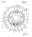
- Each of the drum brakes 18, 20 has a backing plate 30 and a rotary drum 34.
- the backing plate 30 as a non-rotary body is attached to a body (not shown) of the vehicle.
- the drum 34 has an inner circumferential surface that serves as a friction surface 32, and is rotatable together with the wheel.
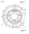
- An anchor member 36 and an adjuster 38 (that serves as a transmitting member) are provided in two portions of the backing plate 30 which are spaced apart from each other in a direction of diameter of the backing plate 30.
- the anchor .member 36 is fixed to the backing plate 30 while the adjuster 38 is of a so-called float type.
- a pair of arcuate-shaped brake shoes 40a, 40b are disposed to be opposed to the inner circumferential surface of the drum 34.
- the pair of brake shoes 40a, 40b are attached to the backing plate 30 through respective shoe hold-down devices 42a, 42b such that the brake shoes 40a, 40b are movable along a surface of the backing plate 30.
- the backing plate 30 has, in its central portion, a through-hole that is provided for allowing an axle shaft (not shown) to pass therethrough.
- Each of the brake shoes 40a, 40b has opposite end portions, one of which can be referred to as a transmitting-member-side end portion and the other of which can be referred to as an anchor-member-side end portion.
- the transmitting-member-side end portions of the respective brake shoes 40a, 40b are operatively connected to each other through the adjuster 38, while the anchor-member-side end portions of the respective brake shoes 40a, 40b are in contact with the anchor member 36, such that the brake shoes 40a, 40b are pivotably held by the adjuster 38 and the anchor member 36.
- Each of the transmitting-member-side end portions of the respective brake shoes 40a, 40b is biased or forced, by an adjuster spring 44, in a direction toward the adjuster 38.
- Each of the anchor-member-side end portions of the respective brake shoes 40a, 40b is biased or forced, by a return spring 45, in a direction toward the anchor member 36.
- the brake shoes 40a, 40b have respective outer circumferential surfaces on which respective brake linings 46a, 46b serving as friction material members are disposed, so that a friction force is generated between the friction surface 32 of the drum 34 and each of the brake linings 46a, 46b upon contact with each of the brake linings 46a, 46b with the friction surface 32 of the drum 34.
- the adjuster 38 is operated to adjust a clearance between the drum 34 and each of the brake linings 46a, 46b, depending on wear of the brake shoes 40a, 40b.
- the adjuster 38 functions as a transmitting member configured to transmit a circumferential force applied to one of the brake shoes 40a, 40b, to the other of the brake shoes 40a, 40b.
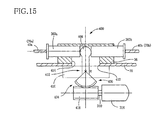
- Each of the drum brakes 18, 20 further has a pressing device 50, which includes an electric motor 52 as an electric drive source, a motion converting mechanism 54, a shoe pressing rod 56 as an acting member and a maintaining mechanism 58, as shown in Figs. 3 and 4 .
- the motion converting mechanism 54 is configured to convert a rotary motion that is to be given from the electric motor 52, into a linear motion that is to be given to the shoe pressing rod 56.
- the shoe pressing rod 56 is provided by a rigid member, and does not have flexibility unlike a cable. That is, each of the drum brakes 18, 20 does not have a brake lever, and is not operated through a cable. As shown in Fig.
- the motion converting mechanism 54 includes: a housing 60;, a threaded member 64 held by the housing 60 through a pair of bearings 66 so as to be rotatable relative to the housing 60; and the above-described shoe pressing rod 56 held on a radially inner side of the threaded member 64 and axially movable relative to the housing 60.
- the threaded member 64 has a first threaded portion (internally threaded portion) 70 provided in its inner circumferential surface
- the shoe pressing rod 56 has a second threaded portion (externally threaded portion) 72 provided in an axially intermediate portion of its outer circumferential surface, such that the first and second threaded portions 70, 72 are held in thread engagement with each other.
- the shoe pressing rod 56 have shoe engaging portions 74a, 74b respectively provided in its axially opposite end portions.
- the shoe engaging portions 74, 74b have shapes suitable for gripping webs 76a, 76b of the respective brake shoes 40a, 40b, so as to function as a preventer for preventing rotation of the shoe pressing rod 56.
- Each of the shoe engaging portions 74a, 74b has a size and a shape, which enable each of the shoe engaging portion 74a, 74b to grip a corresponding one of the webs 76a, 76b from its opposite sides even when the shoe pressing rod 56 is moved rightward or leftward as seen in Fig.
- the threaded member 64 serves as a first threaded member while the shoe pressing rod 56 serves as a second threaded member.
- the shoe pressing rod 56 and the second threaded member are formed integrally with each other in the present embodiment.
- a maintaining mechanism in the form of a worm gear set 58 that includes a worm 80 and a worm wheel 82.
- the worm 80 is formed integrally with an output shaft 83 of the electric motor 52, so as to be rotatable together with the output shaft 83.
- the threaded member 64 is fitted in the worm wheel 82 so as to be disposed on a radially inner side of the worm wheel 82.
- a key 84 is provided between the worm wheel 82 and the threaded member 64, so as to assure rotation of the threaded member 64 together with the worm wheel 82.
- the worm wheel 82 is held by the housing 60 so as to be axially unmovable relative to the housing 60.
- the threaded member 64 is inhibited from being axially moved so that a rotary motion of the threaded member 64 is converted into a linear motion of the shoe pressing rod 56, i.e., a relative movement of the shoe pressing rod 56 in its axial direction.
- a large force is applied to the shoe pressing rod 56 in absence of an electric current supplied to the electric motor 52, the electric motor 52 is prevented from being rotated by the large force, owing to the worm gear set 58 that serves as the maintaining mechanism as well as a speed reducer.
- the housing 60 is fixedly held by the anchor member 36 having opposed surfaces 90, 92 opposed to respective surfaces of the housing 60 that are perpendicular to the axial direction.
- the left-sided pressing-force sensor 94 is of pressure-sensing type, and is configured to detect a pressing force (more precisely, a reaction acting against the pressing force) which is applied from the shoe pressing rod 56 to the right-sided brake shoe 40b.
- the right-side pressing-force sensor 94 is also of pressure-sensing type, and is configured to detect a pressing force (more precisely, a reaction acting against the pressing force) which is applied from the shoe pressing rod 56 to the left-sided brake shoe 40a. It is noted that each of the housing 60 and the anchor member 36 may be constituted by a plurality of members.
- the electric motor 52 is controlled in accordance with commands supplied from a parking brake ECU (PKBECU) 200, which is constituted principally by a computer and includes an input/output portion 202, an executing portion 204 and a storage portion 206.
- a parking brake ECU PKBECU
- the parking brake ECU 200 is connected, via a CAN (Car Area Network) 218, to other computers provided in the vehicle such as a slip control ECU (VSCECU) 220 and an engine transmission ECU (ETCECU) 222.
- a slip control ECU VSCECU
- ETCECU engine transmission ECU
- a longitudinal acceleration sensor 226 as a slop detector
- a shift-position sensor 228 as a shift-position detector, respectively, for example.
- information such as an actual longitudinal acceleration and a current shift position is supplied to the parking brake ECU 200 via the slip control ECU 220, engine transmission ECU 222 and CAN 218.
- the longitudinal acceleration sensor 226 includes two detecting portions each arranged to detect an acceleration directed in a direction inclined with respect to a longitudinal direction of the vehicle by an angle of 45°, so that an acceleration of the vehicle in the longitudinal direction is obtained based on values respectively detected by the detecting portions. Even where one of the two detecting portions suffers from a failure, the longitudinal acceleration can be obtained by the other of the two detecting portions.
- the above-described pressing-force sensors 94, 96 may be replaced with other pressing-force sensors, which are attached to the respective shoe engaging portions 74a, 74b of the shoe pressing rod 56 that are to be brought into contact with the respective brake shoes 40a, 40b. In this arrangement, the pressing force applied to each of the brake shoes 40a, 40b can be directly detected. This arrangement is preferable, particularly, where the housing 60 is provided integrally with the anchor member 36. Further, the above-described pressing-force sensors 94, 96 may be replaced with still other pressing-force sensors, which are attached to respective portions of the anchor member 36 that are to be brought into contact with the reactive brake shoes 40a, 40b. In this arrangement, it is possible to detect a pressing force obtained owing to a servo effect.
- the parking brake switch 214 is to be operated for commanding activation (hereinafter referred to as "locking" where appropriate) of the parking brakes 18, 20 and for commanding release of the parking brakes 18, 20.
- the parking brake switch 214 may have a locking operation portion and a releasing operation portion.
- the locking operation portion is operated, it is judged that there is issued a command requesting activation or locking of the parking brakes 18, 20.
- the releasing operation portion is operated, it is judged that there is issued a command requesting release of the parking brakes 18, 20.
- the shift-position sensor 228 may be configured to detect either or indirectly a selected shift position of a transmission of the vehicle. For detecting indirectly the selected shift position, the shift-position sensor 228 may be arranged to detect an actual position of a shift operation lever of the vehicle.
- a torque application direction (in which a torque is to be applied to each of the wheels 14, 16 in a brake effect state in which the parking brakes 18, 20 have been brought into effect) is predicted.
- the shoe pressing rod 56 is moved toward a primary one of the brake shoes 40a, 40b that serves as a primary shoe upon application of the torque to each of the wheels 14, 16.
- the primary shoe is defined as a shoe opposite to another shoe that is brought into contact with the anchor member 36 when the brake shoes 40a, 40b are moved, by the applied torque, in a circumferential direction along the inner circumferential surface of the rotary drum 34.
- the shoe pressing rod 56 which is moved toward the primary shoe, is positioned in an acting position so as to act directly on the primary shoe, namely, is brought into direct contact with the primary shoe so as to apply a pressing force to the primary shoe.
- the pressing rod 56 can be reliably brought into contact with the primary shoe so as to act directly on the primary shoe when being moved from the neutral position to the primary shoe.
- the shoe pressing rod 56 is moved leftward as seen in Fig. 3 , so as to apply the pressing force to the brake shoe 40a serving as the primary shoe.
- the pressing force applied to the brake shoe 40a is transmitted, via the adjuster 38, to the brake shoe 40b serving as the secondary shoe, whereby the brake shoe 40b is pressed against the anchor member 36.
- the shoe pressing rod 56 is moved rightward as seen in Fig. 3 , so as to apply the pressing force to the brake shoe 40b serving as the primary shoe.
- the pressing force applied to the brake shoe 40b is transmitted, via the adjuster 38, to the brake shoe 40a serving as the secondary shoe, whereby the brake shoe 40a is pressed against the anchor member 36.
- each of the wheels 14, 16 receives a torque originating from a gravity or a drive torque applied from a vehicle drive power source.
- ⁇ represents an angle of inclination of the sloped road surface.
- the inclination angle ⁇ (i.e, degree and direction of the inclination) can be obtained based on the longitudinal acceleration G.
- the parking brakes 18, 20 are activated by operating the locking operation portion of the parking brake switch 214 even when the currently selected shift position of the transmission is other than a parking position during activation of the drive power source.
- the torque application direction can be predicted based on the currently selected shift position of the transmission as long as the currently selected shift position is other than a neutral position.
- the currently selected shift position is a drive (D) position, a first (1st) gear position or a second (2nd) gear position, it is predicted that the torque applied to each of the wheels 14, 16 will act on the forward rotation direction P upon release of the service brakes 24.
- the torque application direction is predicted based on a direction of inclination of the sloped road surface.
- the torque application direction is predicted based on a direction of a drive torque applied from the drive power source. It is noted that the torque application direction may be predicted based on both of the inclination of the road surface and the drive torque, namely, based on the degree and direction of the inclination of the road surface and the amount and direction of the drive torque.
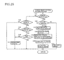
- Fig. 5 is a flow chart showing a parking brake control routine program that is repeatedly executed at a predetermined time interval.
- This routine program is initiated with step S1 that is implemented to judge whether the parking brake switch 214 has been operated or not.
- step S2 is implemented to judge whether the locking operation portion of the parking brake switch 214 has been operated or not, namely, a locking command (requesting activation or locking of the parking brakes 18, 20) has been issued or not.
- step S3 is implemented to obtain a direction of the inclination of the road surface, based on a value detected by the longitudinal acceleration sensor 226, and step S4 is implemented to obtain a direction of the drive torque, based on a detection made by the shift-position sensor 228.
- Step S5 is implemented to predict the torque application direction (i.e., a direction of a torque that is to be applied to each of the wheels 14, 16 upon release of the service brakes 24), and then to determine a direction in which the electric motor 52 is to be rotated, i.e., a direction in which the shoe pressing rod 56 is to be moved.
- Step S5 is followed by step S6 that is implemented to control an electric current to be supplied to the electric motor 52 so as to activate the parking brakes 18, 20 so that the shoe pressing rod 56 is moved to apply a pressing force to the primary shoe.
- step S2 when the releasing operation portion of the parking brake switch 214 has been operated, namely, when a releasing command (requesting release of the parking brakes 18, 20) has been issued, a negative judgment (NO) is obtained in step S2 whereby the control flow goes to step S7 in which the parking brakes 18, 20 are released by controlling the electric current supplied to the electric motor 52.
- the shoe pressing rod 56 is returned from the acting position to the neutral position.
- step S6 a brake activating routine program as a sub-routine program of the parking brake control routine program is executed as shown in a flow chart of Fig. 6 .
- an amount of pressing force which is to be generated upon activation of each of the parking brakes 18, 20, is predetermined.
- the electric motor 52 is activated such that an actual amount of pressing force is equalized to the predetermined amount of pressing force (i.e., target pressing force amount). Since there is a certain relationship between the pressing force amount and a braking force amount that can be generated between a road surface and each tire, a desired braking force amount can be obtained by equalizing the actual pressing force amount to the target pressing force amount.
- the electric motor 52 is a DC motor or the like
- a load applied to the electric motor 52 is made larger when the pressing force amount is relatively large than when the pressing force amount is relatively small, so that a value of electric current flowing through the motor 52 is made larger when the pressing force amount is relatively large. Therefore, there is a certain relationship between the electric current value and the pressing force amount, so that the pressing force amount is dependent on the electric current value. In view of these relationships, it can be judged that the pressing force amount reaches the target pressing force amount when the value of electric current flowing through the motor 52 reaches a target electric current value.
- step S31 is implemented to output a command requesting the electric motor 52 to be rotated in the direction that has been determined in step S5.
- step S31 is followed by steps S32 and S33.
- step S32 the number of rotations (i.e., angular position) of the motor 52 is detected, namely, a counted value indicated by a rotation number counter is read.
- step S33 the electric current value is detected.
- step S34 is implemented to judge whether the detected electric current value has reached the target electric current value or not. Steps S32 and S33 are repeatedly implemented until the detected electric current value reaches the target electric current value, namely, until a positive judgment (YES) is obtained in step S34.
- step S35 is implemented to stop the motor 52 with the supplied electric current being zeroed.
- step S36 is implemented to memorize the number of rotations of the motor 52 that have been required by movement of the shoe pressing rod 56 from the neutral position to the acting position.
- the shoe pressing rod 56 acts on the primary shoe so as to apply the pressing force to the primary shoe.
- the maintaining mechanism 58 prevents the motor 52 from being rotated, so as to maintain the pressing force which is applied to the primary shoe and which forces the brake linings 46a, 46b as the friction material members against the friction surface 32 as the inner circumferential surface of the rotary drum 34.
- step S7 a brake releasing routine program as a sub-routine program of the parking brake control routine program is executed as shown in a flow chart of Fig. 7 .
- This brake releasing routine program is initiated with step S51 that is implemented to output a command requesting the electric motor 52 to be rotated in a reverse direction that is opposite to the direction of the rotation made in the brake activating routine program of S6.
- Step S51 is followed by steps S52 and S53.
- step S52 the number of rotations of the motor 52 is detected, namely, a counted value of the rotation number counter is read.
- the number of rotations detected in this step S52 is the number of rotations in the reverse direction that is opposite to the direction of the rotation made in the brake activating routine program of S6.
- step S53 it is judged whether the number of rotations in the reverse direction becomes equal to the number of rotations that has been memorized in step S36. Steps S52 and S53 are repeatedly implemented until the number of rotations counted in step S52 becomes equal to the memorized number, namely, until a positive judgment (YES) is obtained in step S53. When the counted number becomes equal to the memorized number, step S54 is implemented to stop the motor 52 so that the shoe pressing rod 56 is positioned in the neutral position. Thus, a diameter defined by the pair of arcuate-shaped brake shoes 40a, 40b is reduced by the return spring 45 so that each of the parking brakes 18, 20 is released.
- the parking brake ECU 200 includes portions which are assigned to store and implement steps S1-S6 of the parking brake control routine program and which constitute at least a part of a pressing-force controller.
- the above-described portion includes portions which are assigned to store and implement steps S3 and S5 and which constitute a torque direction predictor.
- the torque direction predictor cooperates with the pressing device 50 to constitute at least a part of a parking-brake operating apparatus.
- the pressing-force controller serves also as a parking-brake controlling portion and a motor controlling portion.
- the number of rotations of the electric motor 52 is counted when the shoe pressing rod 56 is moved to the acting position and also when the shoe pressing rod 56 is returned to the neutral position, as described above.
- this arrangement may be modified such that the counted number is increased when the shoe pressing rod 56 is moved to the acting position and such that the counted number is reduced when the shoe pressing rod 56 is returned to the neutral position.
- step S53 is implemented to judge whether the counted number becomes equal to zero (that is a counted number corresponding to the neutral position). In this modified arrangement, it is unnecessary to memorize the counted number in the brake activating routine program of Fig. 6 , thereby making it possible to eliminate step S36.
- the electric current supplied to the electric motor 52 is controlled in execution of the brake activating routine program such that the value of the electric current flowing through the motor 52 reaches the target electric current value.
- the supplied electric current may be controlled in execution of the brake activating routine program such that the amount of pressing force detected by each of the pressing-force sensors 94, 96 reaches a target pressing force amount, and may be controlled in execution of the brake releasing routine program so as to rotate the motor 52 in the reverse direction until the amount of pressing force detected by each of the pressing-force sensors 94, 96 becomes substantially zero (i.e., an amount corresponding to the neutral position).
- Figs. 9 and 10 are flow charts showing another parking brake control routine program as an example of this modified arrangement.
- steps S33a is implemented to cause the pressing-force sensor 94 to detect the pressing force (for example, when the shoe pressing rod 56 is moved leftward as seen in Fig. 3 ), and step S34a is implemented to judge whether the detected pressing force amount has reached the target pressing force amount. Until the detected amount reaches the target amount, steps S33a and S34a are repeatedly implemented. When the detected amount has reached the target amount, step S35 is implemented to stop the motor 52.
- step S52a is implemented to cause both of the pressing-force sensors 94, 96 to detect the pressing force
- step S54a is implemented to judge whether both of the detected pressing force amounts have reached substantially zero, namely, whether both of the detected pressing force amounts become not larger than a predetermined threshold amount that can be regarded as substantially zero. It is judged that the shoe pressing rod 56 has been returned when both of the detected pressing force amounts become not larger than the predetermined threshold amount, and step S54 is implemented to stop the motor 52.
- the shoe pressing rod 56 could be returned too much (could be erroneously moved to a right side of the neutral position).
- the shoe pressing rod 56 can be returned reliably to the neutral position, because the motor 52 is controlled such that not only the amount detected by the pressing-force sensor 96 but also the amount detected by the pressing-force sensor 94 is not larger than the predetermined threshold amount.
- the judgment as to whether the shoe pressing rod 56 has been returned to the neutral position is made based on both of the amounts detected by the pressing-force sensors 94, 96. However, the judgment may be made by seeing if the amount detected by the pressing-force detector 96 is held not larger than the predetermined threshold amount for a predetermined length of time. That is, in this modified example, it is judged that the shoe pressing rod 56 has been returned to the neutral position when the amount detected by the pressing-force detector 96 had become not larger than the predetermined threshold amount and such a state of being not larger than the predetermined threshold amount has been maintained for at least the predetermined length of time.
- a stroke sensor may be provided for detecting a stroke movement of the shoe pressing rod 56, so that the activation of the electric motor 52 can be controlled based on the detected stroke movement such that an amount of the detected stroke amount reaches a target amount.
- the pressing device 50 may be otherwise modified.
- the electric motor 52 and the pressing mechanism are provided on one and the other of opposite sides of the backing plate 30, respectively, the motor 52 and the pressing mechanism may be provided on the same one of the opposite sides of the backing plate 30, if there is a space available for their provision.
- a thread formed in each of the threaded portions 70, 72 may have a shape that is not particularly limited.
- the thread may have a small lead angle or may be of an acme thread, so that the motion converting mechanism serves also as the above-described maintaining mechanism.
- Figs. 11 and 12 show a pressing device 300 which can be provided, in place of the above-described pressing device 50, in each of the drum brakes 18, 20.
- the pressing device 300 includes: a motion converting mechanism 302 having a rack-pinion mechanism; a speed-reducer built-in motor 304 as the electric drive source; and a housing that is provided by the anchor member 36.
- the motion converting mechanism 302 includes: a pinion 312 which is provided by a spur gear and which is rotatable integrally with an output shaft 310 of the motor 304; and a rack 314 which is engaged with the pinion 312 and which is held by the anchor member 36 (that functions as the housing).
- the rack 314 is movable in its longitudinal direction relative to the anchor member 36, and is provided integrally with the shoe pressing rod.
- the motor 304 includes an electric motor 320 and a speed reducer 322 which may include a harmonic gear set or a planetary gear set and which functions also as the maintaining mechanism.
- the speed reducer 322 includes the planetary gear set having a sun gear and a carrier (carrying planetary gears)
- the sun gear is connected to the output shaft of the electric motor 320 while the carrier is connected to the output shaft 310 of the speed-reducer built-in motor 304.
- the planetary gear set may be replaced with a planetary gear mechanism including a plurality of planetary gear sets.
- the speed reducer 322 includes the harmonic drive set or the planetary gear set, it is possible to prevent the electric motor 320 from being rotated, even when a large force is applied to the motor 320 via the brake shoes 40a, 40b and the shoe pressing rod (rack) 314 in absence of an electric current supplied to the motor 320.
- the shoe pressing rod (rack) 314 is provided with the above-described shoe engaging portions 74a, 74b since a preventer for preventing rotation of the shoe pressing rod 314 is not essential.
- the motion converting mechanism 302 and the shoe pressing rod 314 cooperate with each other to constitute at least a part of the pressing mechanism.
- the shoe pressing rod 314 constitutes also a part of the motion converting mechanism 302.
- the electric motor 320 may be provided by an ultrasonic motor. In such a case, the electric motor 320 serves also as the maintaining mechanism.
- Figs. 13 and 14 show a pressing device 350 which can be provided, in place of the above-described pressing device 50, in each of the drum brakes 18, 20.
- the pressing device 350 includes: a motion converting mechanism 354 having an eccentric cam 352; and a pair of shoe pressing rods 360a, 360b.
- the anchor member 36 has a through-hole 372 extending therethrough in its thickness direction (i.e., a direction perpendicular to the backing plate 30 and parallel to an axle shaft of the vehicle), such that the output shaft 310 of the speed-reducer built-in motor 304 is relatively rotatably held in the through-hole 372 via a bearing.
- the eccentric cam 352 is provided integrally with the output shaft 310 so as to be rotatable together with the output shaft 310, such that a center C of the eccentric cam 352 is distant from an axis M of the output shaft 310 by a radial distance d as shown in Fig. 14 .
- the pair of shoe pressing rods 360a, 360b are disposed to be opposed to an outer circumferential surface of the eccentric cam 352 as a cam surface of the cam 352, and are held by the anchor member 36, such that the shoe pressing rods 360a, 360b are movable in its axial direction relative to the anchor member 36.
- the eccentric cam 356 is positioned in a neutral position indicated by solid line in the non-effect state in which each of the parking brakes 18, 20 is not being in effect. While the eccentric cam 356 is positioned in the neutral position, the center C is positioned in a position C 0 lying on a center line of the motion converting mechanism 354, which line is located in a center of the mechanism 354 in the axial direction of the shoe pressing rods 360a, 360b, so that the center M of the output shaft 310 is distant from rear end surfaces 380a, 380b of the respective shoe pressing rods 360a, 360b by substantially the same distance.
- the eccentric cam 352 When the predicted torque application direction corresponds to the forward rotation direction P, the eccentric cam 352 is rotated to an angular position indicated by broke line as a result of rotation of the motor 304 upon activation of each of the parking brakes 18, 20, so that the center C is positioned in a position C 1 whereby the shoe pressing rod 360 is moved leftward so as to act directly on the left-sided brake shoe 40a and to apply a pressing force to the brake shoe 40a.
- the eccentric cam 352 could be in contact at its outer circumferential surface with not only the rear end surface 380a of the shoe pressing rod 360a but also the rear end surface 380b of the shoe pressing rod 380b.
- the shoe pressing rod 360b is not moved rightward, and accordingly the shoe pressing rod 360b does not apply a pressing force to the right-sided brake shoe 40b.
- the eccentric cam 352 is rotated to an angular position indicated by one-dot chain line as a result of reverse rotation of the motor 304 upon activation of each of the parking brakes 18, 20, so that the center C is positioned in a position C 2 whereby the shoe pressing rod 360 is moved rightward so as to act directly on the right-sided brake shoe 40b and to apply a pressing force to the brake shoe 40b.
- the eccentric cam 352 Upon release of each of the parking brakes 18, 20, the eccentric cam 352 is returned to the neutral position indicated by the solid line, whereby the brake shoes 40a, 40b and the shoe pressing rods 360a, 360b are returned to their neutral positions (non-acting positions) by the return spring 45.
- the motion converting mechanism 354 can be disposed on one of opposite sides of the backing plate 30 in which the brake shoes 40a, 40b are disposed, even if a space defined on the same side is small.
- the motion converting mechanism 354, shoe pressing rods 360a, 360b and anchor member 36 cooperate to constitute as least a part of the pressing mechanism.
- the eccentric cam 352 cooperates with a construction for axially movably holding the shoe pressing rods 360a, 360b, to constitute at least a part of the motion converting mechanism 354.
- the eccentric cam 352 may be modified, as shown in Fig. 18 , such that the cam 352 can be brought into contact at its outer circumferential surface with the brake shoes 40a, 40b so as to act directly on the brake shoes 40a, 40b and to apply a pressing force to each of the brake shoes 40a, 40b.
- the shoe pressing rods 360a, 360b can be eliminated.
- the cam surface does not necessarily have to be provided by the outer circumferential surface, but may be provided by any other surface of the cam 352.
- Fig. 15 shows a pressing device 400 which can be provided, in place of the above-described pressing device 50, in each of the drum brakes 18, 20.
- the pressing device 400 includes a motion converting mechanism 404 in addition to the pair of shoe pressing rods 360a, 360b.
- the motion converting mechanism 404 has a lever member 402 that is formed integrally with a sector gear (worm wheel) 406.
- the lever member 402 has a distal end portion 408 that is interposed between the shoe pressing rods 360a, 360b.
- the lever member 402 includes an intermediate portion extending to pass through elongated holes 412, 414 that are provided in the backing plate 30 and the anchor member 36, respectively.
- the lever member 402 is held by a lever-member holder 416 disposed on one of opposite sides of the backing plate 30 that is remote from the brake shoes 40a, 40b, and is pivotable about a pivot center R.
- the elongated holes 412, 414 cooperate with each other to constitute a guide portion for guiding the lever member 402.
- the sector gear 406 of the lever member 402 is engaged with a worm 418 that is rotatable integrally with the output shaft 310 of the speed-reducer built-in motor 304.
- the lever member 402 Upon activation of each of the parking brakes 18, 20, the lever member 402 is pivoted by rotation of the speed-reducer built-in motor 304 whereby a selected one of the shoe pressing rods 360a, 360b is moved.
- the shoe pressing rod 360a is moved to apply a pressing force to the left-sided brake shoe 40a.
- the shoe pressing rod 360b is moved to apply a pressing force to the right-sided brake shoe 40b.
- the lever member 402 is returned to a neutral position (neutral posture) by reverse rotation of the speed-reducer built-in motor 304, whereby the brake shoes 40a, 40b and the shoe pressing rods 360a, 360b are returned to their neutral positions (non-acting positions) by the return spring 45.
- the motion converting mechanism 404, shoe pressing rods 360a, 360b and anchor member 36 cooperate to constitute as least a part of the pressing mechanism.
- the shoe pressing rods 360a, 360b may be provided by a single rod, so as to be movable integrally with each other. It is noted that the lever member 402 may be modified such that the lever member 402 can be brought into contact at its distal end portion 408 with the brake shoes 40a, 40b so as to act directly on the brake shoes 40a, 40b and to apply a pressing force to each of the brake shoes 40a, 40b. In such a modification, the shoe pressing rods 360a, 360b can be eliminated. Further, where the worm 418 and the sector gear 406 cooperate with each other to have a non-reversible characteristic, the worm 418 and the sector gear 406 cooperate with each other to function also as the maintaining mechanism. In such a case, the speed reducer 322 does not necessarily have to include a gear set having a non-reversible characteristic. Further, the speed reducer as such is not essential.
- the brake system incorporating the duo-servo drum brakes which is constructed according to the above-described embodiment, may be adapted to serve as a service brake system.
- a pressing force can be applied to the primary shoe by activating the electric motor in response to a command requesting activation of service brakes.
- Figs. 16 and 17 show a pressing device 500 which can be provided, in place of the above-described pressing device 50, in each of the drum brakes 18, 20, so that each of the drum brakes 18, 20 works as an uni-servo drum brake rather than as a duo-servo drum brake.
- the pressing device 500 is substantially identical in construction with the pressing device 50, except for a shoe pressing rod 502 serving as a movable member.
- a shoe engaging portion 504 is provided in one of opposite end portions of the shoe pressing rod 502 that is close to the right-sided brake shoe 40a, while no engaging portion is provided in the other of the opposite end portions of the shoe pressing rod 502. In this arrangement shown in Figs.
- the shoe pressing rod 502 does not act directly on the right-sided brake shoe 40b and accordingly does not apply a pressing force to the brake shoe 40b.
- the electric motor 52 is activated without predicting the torque application direction, such that the shoe pressing rod 502 is moved leftward so as to be brought into contact with the brake shoe 40a and to act directly on the brake shoe 40a, whereby a pressing force is applied to the left-sided brake shoe 40a.
- the pressing force thus applied to the left-sided brake shoe 40a constitutes a circumferential force, and is transmitted to the right-sided brake shoe 40b via the adjuster 38, so that the right-sided brake shoe 40b is pressed against the anchor member 36.
- the left-sided brake shoe 40a to which the pressing force is applied, serves as the primary shoe when the torque is applied to each of the wheels 14, 16 in the forward rotation direction P. Therefore, there is an advantage that a large braking force can be obtained when each of the parking brakes 18, 20 is activated during a forward running of the vehicle.
- the pressing device 500 may be replaced with any one of the above-described pressing devices 50, 300, 350, 400.
- reference signs 1010, 1012 denote an electric motor and a clutch built-in type motion converting mechanism, respectively.
- the clutch built-in type motion converting mechanism 1012 is configured to convert a rotary motion that is to be given from an output shaft 1052 of the electric motor 1010, into a linear motion that is to be given to an output member, and to prevent the electric motor 1010 from being rotated by a force applied to the output member.
- reference signs 1016, 1014 denote rear right and rear left wheels of a vehicle, respectively
- reference signs 1018, 1020 denote drum brakes that are provided for the respective wheels 1014, 1016.
- the parking brakes 1018, 1020 are connected to the motion converting mechanism 1012 via respective cables 1022, 1024, respectively.
- the cables 1022, 1024 are pulled by activation of the electric motor 1010, each of the parking brakes 1018, 1020 comes into effect.
- the electric motor 1010, motion converting mechanism 1012, cables 1022, 1024 and drum brakes 1018, 1020 cooperate to constitute at least a part of an electrically-operated parking brake mechanism 1030.
- the clutch built-in type motion converting mechanism 1012 includes a gear train 1040, a clutch 1042 and a screw mechanism 1044.
- the gear train 1040 consists of a plurality of gears 1046, 1048, 1050.
- the output shaft 1052 of the electric motor 1010 includes a toothed portion that meshes with the gear 1046, so that rotation of the output shaft 1052 is transmitted to the gear 1050 via the gears 1046, 1048.
- a drive transmission portion 1054 is provided to axially protrude from one of opposite end surfaces of the gear 1050 that is remote from the electric motor 1010.
- the clutch 1042 is provided by a one-way clutch, and includes: a housing 1060; a coil spring 1062 disposed on an inner peripheral side of the housing 1060; and a rotor 1066 rotatable integrally with an output shaft 1064 of the clutch 1042.
- the coil spring 1062 is fitted in the housing 1060 while being slightly compressed in its radial direction in an elastic manner, so that an outer circumferential surface of the coil spring 1062 is held in close contact with an inner circumferential surface of the housing 1060.
- a wire of the coil spring 1062 has opposite end portions 1068, 1070 which protrude inwardly in the radial direction.
- the drive transmission portion 1054 is located in one of two spaces which are circumferentially defined between the two end portions 1068, 1070, while the rotor 1066 is located in the other of the two spaces.
- the drive transmission portion 1054 When the gear 1050 is rotated by rotation of the electric motor 1010, the drive transmission portion 1054 is brought into contact with one of the opposite end portions 1068, 1070 of the wire, so as to rotate the one of the opposite end portions 1068, 1070 in a direction that increases the number of turns of the wire (i.e., in a direction that reduces a diameter of the coil spring 1062), whereby a friction between the outer circumferential surface of the coil spring 1062 and the inner circumferential surface of the housing 1060 is reduced. As a result of the reduction of the friction, the coil spring 1062 and the rotor 1066 are made rotatable, whereby the output shaft 1064 is rotated together with the gear 1050.
- the rotation of the motor 1010 is transmitted to the output shaft 1064 through the clutch 1042.
- the rotor 1066 is brought into contact with one of the opposite end portions 1068, 1070 of the wire, so as to rotate the one of the opposite end portions 1068, 1070 in a direction that reduces the number of turns of the wire (i.e., in a direction that increases the diameter of the coil spring 1062), whereby the friction between the outer circumferential surface of the coil spring 1062 and the inner circumferential surface of the housing 1060 is increased.
- the torque applied to the output shaft 1064 is inhibited, by the clutch 1042, from being transmitted to the gear 1050, so that the electric motor 1010 is not rotated by the torque applied to the output shaft 1064 in absence of the electric current supplied to the motor 1010.
- the screw mechanism 1044 includes: a housing 1080; an externally threaded member 1082 extending in a direction parallel to an axis L of the output shaft 64; an internally threaded member or nut (not shown) held in thread engagement with the externally threaded member 1082; and an equalizer 1084 attached to the nut and pivotable about a pivot axis M relative to the nut.
- the externally threaded member 1082 is rotatably supported by the housing 1080 via a pair of radial bearings 1085 (one of the radial bearings 1085 is not shown) and a needle thrust bearing 1086.
- the equalizer 1084 has arms to which inner cables 1087 of the respective cables 1022, 1024 are connected.
- An engaging protrusion 1088 is provided in a main body of the equalizer 1084, so as to be engaged with a guide (not shown) which is provided in the housing 1080 and which extends in parallel to the axis L. Owing to the engagement of the engaging protrusion 1088 with the guide, the equalizer 1084 is, relative to the housing 1080, unrotatable about the axis L, movable in a direction parallel to the axis L and pivotable about the axis M (i.e., about the engaging protrusion 1088).
- the equalizer 1084 is movable relative to the housing 1080 between two positions, which are indicated by solid line and two-dot chain line, respectively, in Fig. 20 .
- the equalizer 1084 is pivoted about the axis M (i.e., about the engaging protrusion 1088) such that a tension applied to the inner cable 1087 of the cable 1022 (hereinafter simply referred to as "tension applied to the cable 1022) and a tension applied to the inner cable 1087 of the cable 1024 (hereinafter simply referred to as "tension applied to the cable 1024) are equalized to each other.
- a tension sensor 1090 is provided inside the housing 1080 so as to detect the tension applied to the cable 1024. Since the tensions respectively applied to the cables 1022, 1024 are equalized to each other by the equalizer 1084, the tension sensor 1090 practically detects the tension applied to the cable 1022 as well as the tension applied to the cable 1024.
- An emergency releasing device 1092 is provided to release the parking brakes 1018, 1020, for example, in the event of abnormality occurring in the motor 1010.
- the emergency releasing device 1092 includes a cable 1093 and a gear 1095. In operation of the emergency releasing device 1092, the cable 1093 is pushed into an inner portion of the gear 1095, and the gear 1095 is rotated by manually rotating a grip (not shown).
- the rotation of the gear 1095 is transmitted to the gear 1050 via the gears 1046, 1048, and then the rotation of the gear 1050 causes the equalizer 1084 to be moved in a direction that causes the cables 1022, 1024 to be slackened, for thereby releasing the parking brakes 1018, 1020.
- each of the parking brakes 1018, 1020 is a duo-servo drum brake. Therefore, each of the parking brakes 1018, 1020 will be hereinafter referred to as a drum brake where appropriate.
- reference signs 1097, 1098 denote a brake disk and a caliper, respectively, which cooperate with each other to constitute a disk brake 1099 serving as a service brake.
- Each of the drum brakes 1018, 1020 serving as the parking brake is disposed on an inner peripheral side of the brake disk 1097, so as to cooperate with the disk brake 1099 to constitute a so-called "drum in disk brake" in the present embodiment. Since the drum brakes 1018, 1020 are identical in construction with each other, the drum brake 1018 will be described while the drum brake 1020 will not be described.
- the drum brake 1018 has a backing plate 1100 and a rotary drum 1104.
- the backing plate 1100 as a non-rotary body is attached to a body (not shown) of the vehicle.
- the drum 1104 has an inner circumferential surface that serves as a friction surface 1102, and is rotatable together with the wheel.
- An anchor member 1106 and an adjuster 1108 (that serves as a transmitting member) are provided in two portions of the backing plate 1100 which are spaced apart from each other in a direction of diameter of the backing plate 1100.
- the anchor member 1106 is fixed to the backing plate 1100 while the adjuster 1108 is of a so-called float type.
- a pair of arcuate-shaped brake shoes 1110a, 1110b are disposed to be opposed to the inner circumferential surface of the drum 1104.
- the pair of brake shoes 1110a, 1110b are attached to the backing plate 1100 through respective shoe hold-down devices 1112a, 1112b such that the brake shoes 1110a, 1110b are movable along a surface of the backing plate 1100.
- the backing plate 1100 has, in its central portion, a through-hole that is provided for allowing an axle shaft (not shown) to pass therethrough.
- Each of the brake shoes 1110a, 1110b has opposite end portions, one of which can be referred to as a transmitting-member-side end portion and the other of which can be referred to as an anchor-member-side end portion.
- the transmitting-member-side end portions of the respective brake shoes 1110a, 1110b are operatively connected to each other through the adjuster 1108, while the anchor-member-side end portions of the respective brake shoes 1110a, 1110b are in contact with the anchor member 1106, such that the brake shoes 1110a, 1110b are pivotably held by the adjuster 1108 and the anchor member 1106.
- Each of the transmitting-member-side end portions of the respective brake shoes 1110a, 1110b is biased or forced, by an adjuster spring 1114, in a direction toward the adjuster 1108.
- Each of the anchor-member-side end portions of the respective brake shoes 1110a, 1110b is biased or forced, by a return spring 1115, in a direction toward the anchor member 1106.
- the brake shoes 1110a, 1110b have respective outer circumferential surfaces on which respective brake linings 1116a, 1116b serving as friction material members are disposed, so that a friction force is generated between the friction surface 1102 of the drum 1104 and each of the brake linings 1116a, 1116b upon contact with each of the brake linings 1116a, 1116b with the friction surface 1102 of the drum 1104.
- the adjuster 1108 is operated to adjust a clearance between the drum 1104 and each of the brake linings 1116a, 1116b, as needed, depending on degree of wear of the brake shoes 1110a, 1110b.
- the adjuster 1108 functions as a transmitting member configured to transmit a circumferential force applied to one of the brake shoes 1110a, 1110b, to the other of the brake shoes 1110a, 1110b.
- Fig. 23 shows a pressing device 1120 including a brake lever 1122 and a strut 1124.
- the brake lever 1122 and the strut 1124 are supported by head portions of respective bolts 1138, 1140 that are provided to fix the anchor member 1106 to the backing plate 1100, such that the brake lever 1122 and the strut 1124 are movable relative to the bolts 1138, 1140.
- the brake lever 1122 is provided by a plate-like member interposed between two plate-like members that cooperate with each other to constitute the strut 1124.
- the brake lever 1122 and the strut 1124 are connected at their respective end portions through a connecting shaft 1126, and are pivotable about the connecting shaft 1126 relative to each other.
- the brake lever 1122 has an engaging portion 1128 which is distant from the connecting shaft 1126 and located between the connecting shaft 1126 and the backing plate 1100.
- the brake lever 1122 has another engaging portion 1130 which is distant from the connecting shaft 1126 in a direction parallel to the backing plate 1100.
- the brake lever 1122 is engaged at the engaging portion 1128 with the left-sided brake shoe 1110a, and is connected at the engaging portion 1130 to the inner cable 1087 of the cable 1022.
- the inner cable 1087 is guided by an outer tube 1134 fixed at its end portion to a through-hole 1132 that is provided in the backing plate 1100, and extends toward one of opposite sides of the backing plate 1100 that is remote from the brake shoes 1110a, 1110b.
- the strut 1124 has an engaging portion 1135 provided by one of its opposite end portions that is remote from the connecting shaft 1126.
- the strut 1124 is engaged at the engaging portion 1135 with the right-sided brake shoe 1110b.
- the engaging portion 1130 of the brake lever 1122 is positioned on a front side of a center line N of the through-hole 1132 as seen in the reverse rotation direction Q, in a state shown in Fig. 23 .
- the engaging portion 1130 is relatively moved upon relative movement of the pressing device 1120 in a circumferential direction, it is designed that the engaging portion 1130 of the brake lever 1122 is not relatively moved to on a rear side of the center line N as seen in the reverse rotation direction Q.
- the center line N may be considered also as a center line of a fixed end of the cable 1022 at which the cable 1022 is connected to the backing plate 1100.
- the pressing device 1120 are supported at its supported portions 1136, 1137 by the head portions of the respective bolts 1138, 1140.
- the brake lever 1122 is pivoted about a contact point at which the supported portion 1136 and the head portion of the bolt 1138 are held in contact with each other.
- the connecting shaft 1126 and the strut 1124 are moved rightward as seen in Fig. 23 , whereby the right-sided brake shoe 1110b is pressed rightward by the strut 1124.
- a reaction is applied from the brake shoe 1110b to the strut 1124 and is transmitted to the left-sided brake shoe 1110a via the strut 1124, connecting shaft 1126 and brake lever 1122, whereby the left-sided brake shoe 1110a is pressed leftward as seen in Fig. 23 .
- the brake shoes 1110a, 1110b receives respective spreading forces that are the same in amount, so that the brake linings 1116a, 1116b are pressed against the inner circumferential surface 1102 of the drum 1104 by respective forces that are the same in amount.
- a tension applied to the cable 1022 is boosted according to a lever ratio of the brake lever 1122, so that the amount of each of the spreading forces applied to the respective brake shoes 1110a, 1110b is dependent on an amount of the boosted force.
- the amount of each of the spreading forces corresponds to an amount obtained by subtracting amounts of frictions generated between the supported portions 1136, 1137 and the bolts 1138, 1140 from the amount of the boosted force.
- a target amount of the tension is determined based on the relationship of Fig. 24 , and the electric current supplied to the motor 1010 is controlled such that an actual amount of the tension becomes equal to the target amount of the tension.
- a movement restraining mechanism 1150 is provided in vicinity of the anchor member 1106. This movement restraining mechanism 1150 is configured to restrain a selected one of the brake shoes 1110a, 1110b from being moved in a direction away from the anchor member 1106.
- the webs 1151a, 1151b of the respective brake shoes 1110a, 1110b have respective engaging holes 1152a, 1152b as engaging portions.
- the movement restraining mechanism 1150 includes: a pair of movement restraining members in the form of pins (engaging rods) 1160a, 1160b that are provided for the respective engaging holes 1152a, 1152b; a restraining member holder including a pair of holder portions in the form of housings 1162a, 1162b accommodating the respective pins 1160a, 1160b such that each of the pins 1160a, 1160b accommodated in a corresponding one of the housings 1162a, 1162b is linearly movable between its engaging and disengaging positions relative to the corresponding one of the housings 1162a, 1162b in a direction perpendicular to the backing plate 1100; a pair of forcing members in the form of springs 1164a, 1164b biasing or forcing the respective pins 1160a, 1160b toward their respective disengaging positions (reverse ends); and a pair of electric drive sources including solenoids 1166a, 1166b.
- the housings 1162a, 1162b are fixedly disposed in respective portions of the backing plate 1100, which positionally correspond to the engaging holes 1152a, 1152b of the respective brake shoes 1110a, 1110b during the non-effect state.
- Each of the solenoids 1166a, 1166b is configured to generate an electromagnetic drive force forcing a corresponding one of the pins 1160a, 1160b, against a biasing force generated by a corresponding one of the springs 1164a, 1164b, in a direction away from the disengaging position toward the engaging position.
- each of the pins 1160a, 1160b is positioned in the disengaging position by the biasing force of a corresponding one of the springs 1164a, 1164b when the electric current is not supplied to a corresponding one of the solenoids 1166a, 1166b, and is moved to the engaging position by the electromagnetic drive force of a corresponding one of the solenoids 1166a, 1166b when the electric current is supplied to the corresponding one of the solenoids 1166a, 1166b.
- Each of the engaging holes 1152a, 1152b has a shape and a size, which restrain a corresponding one of the brake shoes 1110a, 1110b from being moved in a direction away from the anchor member 1106 and which allow the corresponding one of the brake shoes 1110a, 1110b from being moved in a direction toward the anchor member 1106, when a corresponding one of the pins 1160a, 1160b is being engaged with the each of the engaging holes 1152a, 1152b.
- Each of the above-described engaging holes 1152a, 1152b and pins 1160a, 1160b may be modified to have an anchor-side portion that is defined by an inclined surface.
- the brake shoes 1110a, 1110b are further satisfactorily restrained from being moved away from the anchor member 1106, with engagement of the pins 1160a, 1160b with the engaging holes 1152a, 1152b.
- a parking brake ECU PKBECU
- a parking brake switch 1210 operable by the vehicle driver, the above-described tension sensor 1090 (see Fig.
- the parking brake ECU 1200 is connected, via a CAN (Car Area Network) 1214, to other computers provided in the vehicle such as a slip control ECU (VSCECU) 1220 and an engine transmission ECU (ETCECU) 1222.
- a slip control ECU VSCECU
- ETCECU engine transmission ECU
- To the slip control ECU 1220 there are connected a longitudinal acceleration sensor 1226 as a slop detector and a service brake switch 1227, for example.
- a longitudinal acceleration sensor 1226 as a slop detector, for example.
- the parking brake switch 1210 is to be operated for commanding activation (hereinafter referred to as "locking" where appropriate) of the parking brakes 1018, 1020 and also for commanding release of the parking brakes 1018, 1020.
- the parking brake switch 1210 may have a locking operation portion and a releasing operation portion.
- the locking operation portion is operated, it is judged that there is issued a command requesting activation or locking of the parking brakes 1018, 1020.
- the releasing operation portion is operated, it is judged that there is issued a command requesting release of the parking brakes 1018, 1020.
- the longitudinal acceleration sensor 1226 is provided to detect an acceleration of the vehicle in the longitudinal direction.
- the service brake switch 1227 is placed in its ON state when a service brake operating member (not shown) is being operated, and is placed in its OFF state when the service brake operating member is not being operated.
- the service brakes 1099 can be effective when the service brake operating member is being operated.
- the service brake switch 1227 can be considered as a switch for detecting effect state of the service brakes 1099.
- the service brake switch 1227 may be arranged to detect a hydraulic pressure of the brake cylinder, so as to detect the effect state of the service brakes 1099 based on the detected hydraulic pressure.
- the service brake switch 1227 may be arranged to detect an electric current flowing through the electric motor and a pressing force of the caliper 1098, so as to detect the effect state of the service brakes 1099 based on the detected electric current and pressing force.
- the shift-position sensor 1228 may be configured to detect either or indirectly a selected shift position of a transmission of the vehicle. For detecting directly the selected shift position, the shift-position sensor 1228 may be arranged to detect a currently established state of supply of an electric current to solenoid-operated valves, which state corresponds to the selected shift position. For detecting indirectly the selected shift position, the shift-position sensor 228 may be arranged to detect a current position of a shift operation lever of the vehicle. It can be considered that the current position of the shift operation lever corresponds to the currently selected shift position of the transmission during stop of the vehicle.
- each of the wheels 1014, 1016 receives a torque originating from a gravity when the vehicle is being stopped on an uphill or a downhill. Further, the currently selected shift position of the transmission is other than a parking position and a neutral position, each of the wheels 1014, 1016 receives a drive torque (i.e., torque originating from a vehicle drive power source).
- the pressing device 1120 Upon activation of each of the drum brakes 1018, 1020, the pressing device 1120 applies, to the respective brake shoes 1110a, 1110b, the pressing forces that are the same in amount, as described. However, when the left-sided brake shoe 1110a is easier to be moved than the right-sided brake 1110b due to some factor, the left-sided brake shoe 1110a is spread by the pressing force applied from the pressing device 1120, without the right-sided brake shoe 1110b being spread. The pressing force thus applied to the left-sided brake shoe 1110a constitutes a circumferential force, and is transmitted to the right-sided brake shoe 1110b via the adjuster 1108, so that the right-sided brake shoe 1110b is pressed against the anchor member 1106.
- each of the cables 1022, 1024 is slackened by only a small amount in the event of application of a torque acting in the forward rotation direction P.
- each of the cables 1022, 1024 is slackened by such a degree that reduces the braking force. This is because, upon application of the torque acting in the reverse rotation direction Q, the right-sided brake shoes 1110b is separated from the anchor member 1106 so as to be moved in a circumferential direction, and the circumferential force is transmitted to the left-sided brake shoe 1110a via the adjuster 1108, whereby the left-sided brake shoe 1110a is brought into contact with the anchor member 1106.
- the pair of brake shoes 1110a, 1110b are moved in the circumferential direction, and the pressing device 1120 also is moved in the circumferential direction, whereby each of the cables 1022, 1024 is slackened. It is not commonly known which one of the brake shoes 1110a, 1110b is relatively easy to be moved or which one of them is relatively difficult to be moved. In view of this, in the present embodiment, a selected one of the brake shoes 1110a, 1110b is made difficult to be moved while the other of the brake shoes 1110a, 1110b is necessarily moved by activation of the pressing device 1120.
- Fig. 25 is a flow chart showing a parking brake control routine program that is repeatedly executed at a predetermined time interval.
- This routine program is initiated with step S101 that is implemented to judge whether the parking brake switch 1210 has been operated or not.
- step S102 is implemented to judge whether the locking operation portion of the parking brake switch 1210 has been operated or not, namely, a locking command has been issued or not.
- step S103 is implemented to obtain a direction of the inclination of the road surface, based on a value detected by the longitudinal acceleration sensor 1226
- step S104 is implemented to obtain a direction of the drive torque, based on a detection made by the shift-position sensor 1228.
- Step S105 is implemented to predict the torque application direction (i.e., a direction of a torque that is to be applied to each wheel upon release of the service brakes 1099), and then to select one of the solenoids 1116a, 1116b that is provided for a secondary one of the brake shoes 1110a, 1110b that serves as the secondary shoe upon application of the torque.
- the solenoid 1166b is selected as the one of the solenoids that is provided for the secondary shoe, since the solenoid 1166b is for the right-sided brake shoe 1110b serving as the secondary shoe.
- step S105 is followed by step S106 that is implemented to supply an electric current to the selected solenoid 1166b (for example, when the predicted torque application direction corresponds to the forward rotation direction P), whereby the pin 1160b is moved to the engaging position so as to be engaged with the brake shoe 1110b.
- step S107 the cables 1022, 1024 are pulled whereby the pressing device 1120 is activated.
- step S107 a brake activating routine program as a sub-routine program of the parking brake control routine program is executed as shown in a flow chart of Fig. 26 .
- the brake activating routine program is initiated with step S131 that is implemented to rotate the electric motor 1010 in a predetermined direction.
- step S132 the cable tension is detected by the tension sensor 1090.
- step S133 is followed by step S133 that is implemented to judge whether the detected tension amount has reached a target tension amount.
- the target tension amount is a predetermined amount that enables the vehicle to be held stopped. For, example, the target tension amount is made larger when the degree of inclination of the road surface (on which the vehicle is being stopped) is larger than when the degree of inclination of the road surface is small.
- step S134 is implemented to stop the electric motor 1010.
- the pin 1160b is engaged with the brake shoe 1110b as the secondary shoe so that the brake shoe 1110b is made difficult to be separated from the anchor member 1106. Therefore, the brake shoe 1110a as the primary shoe is moved by activation of the pressing device 1120, while the brake shoe 1110b as the secondary shoe is not moved by activation of the pressing device 1120. The circumferential force applied to the brake shoe 1110a (by activation of the pressing device 1120) is transmitted to the brake shoe 1110b via the adjuster 1108, whereby the brake shoe 1110b is pressed against the anchor member 1106.
- step S108 is implemented to judge whether each of the parking brakes 1018, 1020 is being in effect.
- step S109 is implemented to judge whether the service brake switch 1227 is being placed in its ON state (whether the service brakes 1099 are being in effect).
- step S110 is implemented to judge whether a predetermined length of time has elapsed since the parking brakes 1018, 1020 have been activated (since the electric motor 1010 has been stopped when the detected cable tension amount has reached the target tension amount).
- the predetermined length of time is determined based on a length of time from when the locking operation portion of the parking brake switch 214 is operated by the vehicle driver to when operation of the service brake operating member (not shown) is terminated.
- Steps S101, S108, S109 and S110 are repeatedly implemented so that the solenoid 1166b is held energized, until the predetermined length of time has elapsed while the serve brakes 1099 as well as the parking brakes 1018, 1020 are being in effect.
- steps S101, S108, S109 and S110 if the service brakes 1099 are released, a negative judgment (NO) is obtained in step S109 whereby step S111 is implemented to deenergize the solenoid 1166b.
- the right-sided brake shoe 1110b as the secondary shoe is further pressed against the anchor member 1106 owing to the torque (whose direction has been predicted).
- step S111 is implemented when the predetermined length of time has elapsed, whereby the solenoid 1166b is deenergized. This is because it is not desirable that the solenoid 1166b is energized for an excessively large length of time.
- step S102 a negative judgment (NO) is obtained in step S102 whereby the control flow goes to step S112 that is implemented to release the parking brakes 1018, 1020.
- step S112 a brake releasing routine program as a sub-routine program of the parking brake control routine program is executed as shown in a flow chart of Fig. 26 .
- the brake releasing routine program is initiated with step S151 in which the electric motor 1010 is rotated in a reverse direction that is opposite to the direction of the rotation made in the brake activating routine program of 527. Steps S151 is followed by steps S152 and S153.
- step S152 the cable tension is detected by the tension sensor 1090.
- step S153 it is judged whether the detected tension amount has reached substantially zero, namely, whether the detected tension amount becomes not larger than a predetermined threshold amount that can be regarded as substantially zero. Steps S152 and S153 are repeatedly implemented until the detected tension amount becomes not larger than the predetermined threshold amount.
- the electric current supplied to the electric motor 1010 is zeroed in step S154, so that the pair of brake shoes 1110a, 1110b are returned, by the return spring 1115, to their respective non-effect positions, namely, so that a diameter defined by the pair of brake shoes 1110a, 1110b is reduced whereby the brake shoes 1110a, 1110b are returned to the respective non-effect positions.
- Step S154 is followed by step S155 that is implemented to stop supply of the electric current to the solenoid 1166b.
- step S155 is implemented to stop supply of the electric current to the solenoid 1166b.
- the supply of the electric current to the solenoid 1166b is stopped before the releasing operation portion of the parking brake switch 1210 is operated.
- the releasing operation portion of the parking brake switch 1210 is operated before the supply of the electric current to the solenoid 1166b is stopped. It is not desirable that the supply of the electric current to the solenoid 1166b is maintained.
- Step S155 is implemented to avoid such an undesirable situation.
- the parking brake ECU 1200 includes portions which are assigned to store and implement steps S101-S106 of the parking brake control routine program and which constitute at least a part of a movement-restraining controller.
- the movement-restraining controller cooperates with the movement restraining mechanism 1150 (that includes the solenoids 1166 as the electric drive source and the pins 1160 as the movement restraining members) to constitute a movement restraining device.
- the movement-restraining controller includes portions which are assigned to store and implement steps S101, S102 and S106 of the parking brake control routine program and which constitute at least a part of a drive-source controlling portion.
- the movement-restraining controller includes portions which are assigned to store and implement steps S103, S104 and S105 of the parking brake control routine program and which constitute at least a part of a torque direction predictor.
- the torque direction predictor cooperates with the pressing device 1120 and the movement restraining device to constitute at least a part of a parking-brake operating apparatus.
- the parking brake ECU 1200 includes portions which are assigned to store and implement steps S105 and S106 and which constitute at least a part of pressing-force controller.
- the supply of the electric current to the solenoid 1166 may be stopped immediately after the detected cable tension amount has reached the target tension amount.
- This modified arrangement makes it possible to further reduce an electric power consumed by the solenoid 1166, and is effective especially where the pressing device 1120 is fixed disposed on the backing plate 1100.
- the construction of the movement restraining mechanism 1150 is not limited to that described in the above-described embodiment.
- the springs 1164 are arranged to force the respective pins 1160 toward the respective disengaging positions in the above-described embodiment, the springs may be arranged to force the respective pins toward the respective engaging positions.
- the solenoids 1166 may be held deenergized while the parking brakes 1018, 1020 are being in effect.
- the housings 1162 and the solenoids 1166 may be disposed on one of opposite sides of the backing plate 1100 that is remote from the brake shoes 1110a, 1110b.
- Figs. 28 and 29 show a movement restraining mechanism 1300 which can be provided, in place of the movement restraining mechanism 1150, in each of the drum brakes 1018, 1020.
- the movement restraining mechanism 1300 includes: a pair of movement restraining members in the form of engaging pawls 1302a, 1302b; a restraining member holder having a pair of holder portions in the form of housings 1303a, 1303b holding the respective engaging pawls 1302a, 1302b; a pair of electric drive sources in the form of electric motors 1304a, 1304b that are provided for the respective engaging pawls 1302a, 1302b; and a pair of springs 1306a, 1306b (one of which is not shown) configured to bias or force the respective engaging pawls 1302a, 1302b toward their respective disengaging positions.
- Each of the engaging pawls 1302a, 1302b can be engaged with a corresponding one of engaging portions in the form of cutouts 1298a, 1298b that are provided in the webs 1151a, 1151b of the respective shoes 1110a, 1110b.
- Each of the cutouts 1298a, 1298b is located in a portion of a corresponding one of the webs 1151a, 1151b, which portion is located on an anchor-member-sided one of opposite sides of a central portion of the corresponding one of the webs 1151a, 1151b.
- Each of the housings 1303a, 1303b is disposed in a portion of the backing plate 1100, which portion enables a corresponding one of the engaging pawls 1302a, 1302b to be engaged with a corresponding one of the cutouts 1298a, 1298b during the non-effect state in which the parking brakes 1018, 1020 are not being in effect.
- Each of the housings 1303a, 1303b is unrotatable relative to a corresponding one of output shafts 1316a, 1316b of the respective motors 1304a, 1304b.
- Each of the engaging pawls 1302a, 1302b is rotatable integrally with a corresponding one of the housings 1303a, 1303b.
- Each of the springs 1306a, 1306b is disposed between the backing plate 1100 and a corresponding one of the engaging pawls 1302a, 1302b.
- the motors 1304a, 1304b are fixedly disposed on one of opposite surfaces of the backing plate 1100 that is remote from the pair of brake shoes 1110a, 1110b.
- Each of the cutouts 1298a, 1298b may have a size and a shape which restrain a corresponding one of the brake shoes 1110a, 1110b in a direction away from the anchor member 1106 and which allows the corresponding one of the brake shoes 1110a, 1110b in a direction toward the anchor member 1106, during engagement of each of the cutouts 1298a, 1298b with a corresponding one of the engaging pawls 1302a, 1302b.
- the movement restraining mechanism 1300 is controlled according to routine programs, which are substantially the same as those of Figs. 25-27 except that: step S105 is replaced with a step that is implemented to predict the torque application direction and then to select one of the motors 1304a, 1304b that is provided for the secondary shoe; step S6 is replaced with a step that is implemented to supply an electric current to the selected motor; and steps S111 and S155 are replaced with steps that are implemented to stop the supply of the electric current to the selected motor.
- the motor 1304b is selected to be activated.
- the engaging pawl 1302b is pivoted against biasing force of the spring 1306b, clockwise as seen n Fig. 28 , so as to be engaged with the cutout 1298b.
- the brake shoe 1110b as the secondary shoe is restrained from being moved in a direction away from the anchor member 1106.
- the supply of the electric current to the motor 1304b is stopped upon release of the service brakes 1099.
- the engaging pawl 1302b is returned, by the biasing force of the spring 1306b, to the disengaging position.
- the motor 1304a When the predicted torque application direction corresponds to the reverse rotation direction Q, the motor 1304a is selected to be activated. By the activation of the motor 1304a, the engaging pawl 1302a is pivoted against biasing force of the spring 1306a, counterclockwise as seen in Fig. 28 , so as to be engaged with the cutout 1298a. By the engagement of the engaging pawl 1302a with the cutout 1298a, the brake shoe 1110a as the secondary shoe is restrained from being moved in a direction away from the anchor member 1106. Thus, the reduction of the braking force can be restrained upon actual application of the torque to each wheel, irrespective of whether the direction of the applied toque corresponds to the forward rotation direction P or reverse rotation direction Q.
- the springs 1306a, 1306b are not essential. In such a case without the springs 1306a, 1306b, even if the electric current supplied to the motor 1304 is zeroed while the engaging pawl 1302 is engaged with the cutout 1298, the engagement of the pawl 1302 with the cutout 1298 can be maintained.
- Figs. 30 and 31 show a movement restraining mechanism 1350 which can be provided, in place of the movement restraining mechanism 1150, in each of the drum brakes 1018, 1020.
- This movement restraining mechanism 1350 is substantially identical with the movement restraining mechanism 1300 of Figs. 28 and 29 except for: presence of a wire 1352 interconnecting the housings 1303a, 1303b of the respective engaging pawls 1302a, 1302b; presence of a supporting pin 1354 supporting the housing 1303a that is rotatable relative to the supporting pin 1354; absence of the electric motor 1304a provided for the engaging pawl 1302a; and absence of the spring 1306b provided for the engaging pawl 1302b.
- the wire 1352 is wound on the housings 1303a, 1303b such that the housings 1303a, 1303b are unrotatable relative to each other.
- the movement restraining mechanism 1350 is placed in its first state in which the engaging pawl 1302b is positioned in the engaging position while the engaging pawl 1302a is positioned in the disengaging position owing to a biasing force of the spring 1306a, in absence of an electric current supplied to the electric motor 1304b.
- the electric current is not supplied to the motor 1304b so that the movement restraining mechanism 1350 is held in the first state.
- the brake shoe 1110b is restrained from being separated from the anchor member 1106, upon activation of the pressing device 1120.
- the first state is maintained during in the brake effect state (in which the parking brakes 1018, 1020 are being in effect) and also after release of the parking brakes 1018, 1020. Any problem is not caused by the engagement of the engaging pawl 1302b with the brake shoe 1110b, which is maintained irrespective of whether the parking brakes 1018, 1020 are being in effect or not.
- the movement restraining mechanism 1350 is held in its first state until the mechanism 1350 has to be switched to its second state.
- the electric motor 1304b When the predicted torque application direction corresponds to the reverse rotation direction Q, the electric motor 1304b is activated whereby the engaging pawl 1302b is pivoted to the disengaging position while the engaging pawl 1302a is pivoted to the engaging position against the biasing force of the spring 1306a.
- the movement restraining mechanism 1350 is thus placed in its second state in which the engaging pawl 1302a is engaged with the cutout 1298a while the engaging pawl 1302b is not engaged with the cutout 1298b.
- the brake shoe 1110a is restrained from being moved in a direction away from the anchor member 1106.
- the electric current is kept supplied to the motor 1304b for maintaining an angular position of the output shaft 1316b.
- the electric current supplied to the motor 1304b is zeroed, for example, when the service brakes 1099 are released.
- the engaging pawls 1302a, 1302b are pivoted, by the biasing force of the spring 1306a, clockwise as seen in Fig. 30 , the engaging pawl 1302b is not brought into engagement with the cutout 1298b.
- the brake shoes 1110a, 1110b are returned to their respective non-effect positions so as to release the parking brakes 1018, 1020, the engaging pawl 1302b is brought into engagement with the cutout 1298b whereby the mechanism 1350 is placed in its first state.
- Fig. 32 is a flow chart showing a parking brake control routine program that is repeatedly executed at a predetermined time interval in the arrangement shown in Figs. 30 and 31 .
- the same step numerals will be used to represent steps having the same procedures as those in the above-described parking brake control routine program of Fig. 25 , and description of these steps will be omitted.
- Step S105a is implemented to predict the torque application direction
- step S106a is implemented to judge whether the predicted torque application direction corresponds to the forward rotation direction P.
- step S107 is implemented to pull the cables 1022, 1024.
- step S106b is implemented to activate the motor 1304b, so that step S107 is implemented to pull the cables 1022, 1024 after the mechanism 1350 has been switched to its second state.
- step S108a is implemented to judge whether the mechanism 1350 is in its second state.
- steps S109 and S110 are not implemented.
- steps S109 and S110 are implemented so that the electric motor 1304b is deenergized in step S111a upon release of the service brakes 1099 or upon elapse of a predetermined length of time after activation of the parking brakes 1018, 1020.
- the engaging portion provided in each of the webs 1151 of the respective brake shoes 1110 may take the form of an engaging protrusion in place of the cutout.
- the engaging protrusion may be provided in a portion of the brake shoe 1110, which portion is located between the engaging pawl 1302 and the anchor member 1160 when the engaging protrusion is engaged with the engaging pawl 1302.
- Fig. 33 shows a movement restraining mechanism 1400 which can be provided, in place of the movement restraining mechanism 1150, in each of the drum brakes 1018, 1020.
- the movement restraining mechanism 1400 includes: a housing (holder portion) 1402 fixed relative to the anchor member 1106; a pair of movement restraining members in the form of engaging pawls 1404a, 1404b; and an engaging rod 1406 having longitudinally opposite end portions that provide the engaging pawls 1404a, 1404b.
- the housing 1402 may be provided by either at least a portion of the anchor member 1106 or at least one member fixed to the anchor member 1106.
- Each of the engaging pawls 1404a, 1404b can be engaged with a corresponding one of engaging portions in the form of engaging protrusions 1398a, 1398b that are provided in the webs 1151a, 1151b of the respective shoes 1110a, 1110b.
- Each of the engaging protrusions 1398a, 1398b is located in the anchor-member-side end portion of a corresponding one of the webs 1151a, 1151b, and protrudes from one of opposite surfaces of the corresponding one of the webs 1151a, 1151b that is remote from the backing plate 1100.
- the engaging rod 1406 is held by the housing 1402, and is movable, by activation of electric drive sources, relative to the housing 1402 in a longitudinal direction of the rod 1406.
- the electric drive sources may include solenoids 1408a, 1408b as shown in Fig. 33 , or piezoelectric elements in place of the solenoids 1408a, 1408b.
- the solenoids 1408b is configured to generate an electromagnetic drive force forcing the engaging rod 1406 in a leftward direction as seen in Fig. 33 (hereinafter referred to as the forward rotation direction P although, more precisely, corresponding to a direction tangent to the forward rotation direction P), while the solenoids 1408a is configured to generate an electromagnetic drive force forcing the engaging rod 1406 in a rightward direction as seen in Fig. 33 (hereinafter referred to as the reverse rotation direction Q although, more precisely, corresponding to a direction tangent to the reverse rotation direction Q).
- a selected one of the engaging pawls 1404a, 1404b can be brought into engagement with a corresponding one of the engaging protrusions 1398a, 1398b of the respective brake shoes 1110a, 1110b.
- the engaging pawls 1404a, 1404b which are provided by the respective longitudinally opposite end portions of the engaging rod 1406, are opposed to the respective brake shoes 1110a, 1110b and protrude toward the respective brake shoes 1110a, 1110b.
- a distance between the engaging pawls 1404a, 1404b in the longitudinal direction of the engaging rod 1406 is larger than a distance between engaging protrusions 1398a, 1398b of the respective brake shoes 1110a, 1110b in the non-effect state (i.e., in a state in which the brake shoes 1110a, 1110b are returned to the respective non-effect positions).
- the solenoid 1408b When the predicted torque application direction corresponds to the forward rotation direction P, the solenoid 1408b is energized to generate the electromagnetic drive force forcing the engaging rod 1406 in the forward rotation direction P.
- the engaging rod 1406 is linearly moved in the forward rotation direction P whereby the mechanism 1400 is placed in its first state in which the engaging pawl 1404b is engaged with the engaging protrusion 1398b while the engaging pawl 1404a is disengaged from the engaging protrusion 1398a.
- the brake shoe 1110b is connected to the anchor member 1106 through the engaging rod 1406 whereby the brake shoe 1110b is restrained from being moved in a direction away from the anchor member 1106.
- the brake shoe 1110a is moved whereby the parking brakes 1018, 1020 are brought into effect.
- the service brake switch 1227 is placed in its OFF state, the supply of the electric current to the solenoid 1408b is stopped whereby the application of the electromagnetic drive force to the engaging rod 1406 is stopped.
- the solenoid 1408a is energized to generate the drive force forcing the engaging rod 1406 in the reverse rotation direction Q.
- the engaging rod 1406 is linearly moved in the reverse rotation direction Q whereby the mechanism 1400 is placed in its second state in which the engaging pawl 1404a is engaged with the engaging protrusion 1398a while the engaging pawl 1404b is disengaged from the engaging protrusion 1398b.
- the brake shoe 1110a is connected to the anchor member 1106 through the engaging rod 1406 whereby the brake shoe 1110a is restrained from being moved in a direction away from the anchor member 1106.
- the engaging rod 1406 can be considered to serve as a common movement restraining member that is common to the brake shoes 1110a, 1110b.
- the solenoid 1408b may be replaced with a spring which is disposed between the engaging rod 1406 and the housing 1402 so as to bias or force the engaging rod 1406 in the forward rotation direction P, i.e., in a direction for establishing the first state.
- the engaging rod 1406 is moved, by the electromagnetic drive force of the solenoid 1408a, in the reverse rotation direction Q against a biasing force of the spring.
- Figs. 34A and 34B show a movement restraining mechanism 1450 which can be provided, in place of the movement restraining mechanism 1150, in each of the drum brakes 1018, 1020.
- the movement restraining mechanism 1450 includes: a housing 1452 provided by the anchor member 1106; a pair of movement restraining members in the form of engaging pawls 1462a, 1462b; and an engaging rod 1454 held by the housing 1452 and movable in its longitudinal direction relative to the housing 1452.
- the engaging rod 1454 has slots 1460a, 1460b provided in its longitudinally opposite end portions.
- the engaging pawls 1462a, 1462b are disposed in the longitudinally opposite end portions of the engaging rod 1454 such that the pawls 1462a, 1462b are rotatable about respective pivot shafts 1464a, 1464b.
- the engaging pawls 1462a, 1462b are biased or forced, by respective springs (not shown), toward their respective disengaging positions.
- Each of the slots 1460a, 1460b is elongated in the longitudinal direction of the engaging rod 1454, and has a width and a length which permit a corresponding one of the brake shoes 1110a, 1110b to be accommodated therein and to be movable relative thereto.
- the slot 1460a has widthwise opposite ends that are defined by respective protruding portions 1466a, 1468a of the engaging rod 1454, while the slot 1460b has widthwise opposite ends that are defined by respective protruding portions 1466b, 1468b of the engaging rod 1454.
- the protruding portions 1468a, 1468b are longer than the protruding portions 1466a, 1466b that hold the respective engaging pawls 1462a, 1462b.
- the brake shoe 1110a is gripped between the protruding portion 1468a and the engaging pawl 1462a that are opposed to each other, while the brake shoe 1110b is gripped between the protruding portion 1468b and the engaging pawl 1462b that are opposed to each other.
- the housing 1452 has pressing portions (cam portions) 1470a, 1470b provided by its longitudinal opposite end portions. Each of the pressing portions 1470a, 1470b has a curved surface such that a distance between the curved surface between a corresponding one of the brake shoes 1110a, 1110b is increased as the curved surface extends outwardly in the longitudinal direction.
- the engaging rod 1454 is movable, by activation of electric drive sources, relative to the housing 1452 in the longitudinal direction of the rod 1454. As in the arrangement shown in Fig. 33 , the electric drive sources may include solenoids 1408a, 1408b, or piezoelectric elements in place of the solenoids 1408a, 1408b.
- the brake shoes 1110a, 1110b are held in contact at their respective anchor-member-side end portions with the housing 1452 serving as the anchor member.
- the engaging rod 1454 is moved in the forward rotation direction P.
- the brake shoe 1110a is not brought into contact with a bottom of the slot 1460a, so that a pressing force is not applied to the brake shoe 1110a.
- the engaging pawl 1462b is pressed by the pressing portion 1470b so as to be pivoted to its engaging position, whereby the brake shoe 1110b is gripped by the engaging pawl 1462b and the protruding portion 1468b so as to be restrained from being moved in a circumferential direction.
- the pressing device 1120 provides at least one of the brake shoes 1110a, 1110b with a pressing force acting in a direction causing the brake shoes 1110a, 1110b to be spread, the brake shoe 1110b is held in contact with the housing 1452 serving as the anchor member, since the brake shoe 1110b is restrained from being moved in a direction away from the housing 1452.
- the brake shoe 1110a is moved in a circumferential direction, and a circumferential force is transmitted to the brake shoe 1110b via the adjuster 1108 whereby the brake shoe 1110b is pressed onto the housing 1452.
- the brake shoe 1110b is restrained from being moved in a circumferential direction.
- the engaging rod 1454 is moved in the reverse rotation direction Q.
- the brake shoe 1110b is moved relative to the slot 1460b, while the brake shoe 1110a is gripped by the engaging pawl 1462a and the protruding portion 1468a so as to be restrained from being moved in a direction away from the housing 1452.
- the pressing device 1120 provides at least one of the brake shoes 1110a, 1110b with a pressing force acting in a direction causing the brake shoes 1110a, 1110b to be spread, the brake shoe 1110a is restrained from being moved in a direction away from the housing 1452 and is pressed onto the housing 1452.
- the brake shoes 1110a, 1110b are not provided with respective engaging portions.
- the engaging portions may be provided in respective portions of the webs 1151a, 1151b of the respective brake shoes 1110a, 1110b which are opposed to the respective engaging pawls 1462a, 1462b.
- Each of the engaging portions may be a recess or a hole which may be, for example, shaped to extend in a circumferential direction.
- the protruding portions 1468a, 1468b do not have to be longer than the protruding portions 1466a, 1466b.
Claims (15)
- Système de frein de stationnement pour un véhicule, comprenant :un corps non-rotatif (30 ; 1100) ;un tambour rotatif (34 ; 1104) pouvant tourner en même temps qu'une roue (14, 16 ; 1014, 1016) du véhicule, et ayant une surface circonférentielle intérieure qui fait office de surface de frottement (32 ; 1102) ;une paire de segments de frein (40a, 40b ; 1110a, 1110b) disposés sur un côté périphérique intérieur dudit tambour rotatif, et ayant des surfaces circonférentielles extérieures respectives sur chacune desquelles un élément (46a, 46b : 1116a, 1116b) en matériau de frottement est disposé ;un élément d'ancrage (36 ; 1106) fixé audit corps non rotatif, et disposé entre des parties d'extrémité côté élément d'ancrage des segments de frein respectifs, chacune desdites parties d'extrémité côté élément d'ancrage est pourvue par l'une de parties d'extrémités opposées d'un segment de frein correspondant parmi lesdits segments de frein ; etun élément de transmission (38 ; 1108) inter-reliant des parties d'extrémité côté élément de transmission desdits segments de frein respectifs, chacune desdites parties d'extrémité côté élément de transmission est pourvue par l'autre desdits parties d'extrémités opposées d'un segment de frein correspondant parmi lesdits segments de frein, ledit élément de transmission est configuré, en présence d'une force appliquée à l'un desdits segments de frein et agit dans une direction de circonférence dudit corps non rotatif, pour transmettre la force dudit l'un desdits segments de frein à l'autre desdits segments de frein,ledit système de frein de stationnement est caractérisé par le fait de comprendre en outre :un appareil d'actionnement de frein de stationnement configuré pour prédire une direction d'application de couple dans laquelle un couple doit être appliqué à la roue lors de l'arrêt du véhicule, et pour presser ledit élément en matériau de frottement de chacun desdits segments de frein contre ladite surface circonférentielle intérieure dudit tambour rotatif, en déplaçant un segment de frein primaire parmi lesdits segments de frein qui fait office de segment primaire lors de l'application du couple à la roue, dans une direction éloignée dudit élément d'ancrage, sans déplacer un segment de frein secondaire parmi lesdits segments de frein qui sert de segment secondaire lors de l'application du couple à la roue.
- Système de frein de stationnement selon la revendication 1, dans lequel ledit appareil d'actionnement de frein de stationnement est configuré pour presser ledit élément (46a, 46b) en matériau de frottement desdits segments de frein (40a, 40b) contre ladite surface circonférentielle intérieure dudit tambour rotatif (34), en déplaçant ledit segment de frein primaire parmi lesdits segments de frein dans la direction éloignée dudit élément d'ancrage (36), sans déplacer ledit segment de frein secondaire parmi lesdits segments de frein, indépendamment du fait que la direction d'application de couple correspond à une direction de rotation avant ou à une direction de rotation arrière, de façon à ce que ledit corps non rotatif (30), ledit tambour rotatif, lesdits segments de frein, ledit élément d'ancrage, ledit élément de transmission (38) et ledit appareil d'actionnement de frein de stationnement coopèrent entre eux pour constituer un frein à tambour de type duo-servo (18, 20),
où ledit appareil d'actionnement de frein de stationnement a un dispositif de pressage (50 ; 300 ; 350 ; 400) disposé entre lesdites parties d'extrémité côté élément d'ancrage desdits segments de frein respectifs (40a, 40b),
et où ledit dispositif de pressage comporte (a) une source (52 ; 320) d'entraînement électrique, (b) un mécanisme de pressage (36, 54, 56, 36, 302, 314, 36, 354, 360a, 360b, 36, 360a, 360b, 404) ayant au moins un élément d'action (56 ; 314 ; 360a, 360b) qui est capable d'agir directement sur lesdits segments de frein de façon à ce qu'une force de pressage puisse être appliquée à un segment de frein sélectionné parmi lesdits segments de frein à travers un élément d'action correspondant parmi l'un dudit au moins un élément d'action qui doit être entraîné par ladite source d'entraînement électrique, et (c) une unité de commande (200, S6) de force de pressage qui est configurée pour prédire la direction d'application de couple et pour commander ladite source d'entraînement électrique sur la base de la prédiction de la direction d'application de couple de façon à ce que la force de pressage soit appliquée à travers ledit l'un dudit élément au moins un élément d'action audit segment de frein primaire parmi lesdits segments de frein comme ledit segment de frein sélectionné parmi lesdits segments de frein. - Système de frein de stationnement selon la revendication 2, dans lequel ladite source (52 ; 320) d'entraînement électrique a un moteur électrique (52 ; 320),
où ledit mécanisme de pressage (36, 54, 56, 36, 302, 314) a (b-1) un élément d'action (56 ; 314) comme ledit au moins un élément d'action qui est capable d'agir directement sur lesdits segments de frein (40a, 40b) de façon à ce que la force de pressage puisse être appliquée au segment de frein sélectionné parmi lesdits segments de frein à travers ledit élément d'action qui doit être entraîné par ladite source d'entraînement électrique, et (b-2) un mécanisme (54 ; 302) de conversion de mouvement configuré pour convertir un mouvement rotatif qui doit être fourni dudit moteur électrique, en un mouvement linéaire qui doit être fourni audit élément d'action,
et où ladite unité de commande (200, S6) de force de pressage a une partie (200, S6) de commande de moteur configurée pour commander une direction de rotation dudit moteur électrique, pour commander ainsi une direction de mouvement dudit élément d'action. - Système de frein de stationnement selon la revendication 3, dans lequel ledit mécanisme (54) de conversion de mouvement a (b-2-i) un boîtier (60, 36), (b-2-ii) un premier élément fileté maintenu par ledit boîtier de façon à ce que ledit premier élément fileté soit rotatif par rapport audit boîtier et de façon à ce qu'il soit axialement immobile par rapport audit boîtier, et (b-2-iii) un deuxième élément fileté (56) maintenu par ledit boîtier de façon à ce que ledit deuxième élément fileté soit non-rotatif par rapport audit boîtier et de façon à ce qu'il soit axialement mobile par rapport audit boîtier,
où lesdits premier et deuxième éléments filetés ont des première et deuxième parties filetées respectives (70, 72) qui sont maintenues dans un engagement par vissage l'une avec l'autre,
et où ledit premier élément fileté peut être rotatif par ledit moteur électrique (52) tandis que ledit deuxième élément fileté fournit ledit élément d'action (56), de façon à ce que ledit élément d'action fourni par ledit deuxième élément fileté soit linéairement déplacé lorsque ledit premier élément fileté est mis en rotation par ledit moteur électrique. - Système de frein de stationnement selon la revendication 2, dans lequel ladite source (320) d'entraînement électrique a un moteur électrique (320),
où ledit mécanisme de pressage (36, 354, 360a, 360b ; 36, 360a, 360b, 404) a (b-1) une paire d'éléments d'action (360a, 360b) comme ledit au moins un élément d'action qui sont capables d'agir directement sur les segments de frein respectifs (40a, 40b) de façon à ce que la force de pressage puisse être appliquée au segment de frein sélectionné parmi lesdits segments de frein à travers un élément d'action correspondant parmi lesdits éléments d'action qui doit être entraîné par ledit moteur électrique, et (b-2) un mécanisme (354 ; 404) de conversion de mouvement comportant l'un (b-2-i) d'une came (352) qui doit être mise en rotation par la rotation dudit moteur électrique (320) de façon à ce qu'elle soit capable d'agir sur ledit élément d'action et (b-2-ii) d'un levier (402) qui doit être mis en rotation par la rotation dudit moteur électrique de façon à ce qu'il soit capable d'agir sur ledit élément d'action,
et où ladite unité de commande (200, S6) de force de pressage a une partie (200, S6) de commande de moteur configurée pour commander une direction de la rotation dudit moteur électrique, pour déplacer ainsi un élément d'action sélectionné parmi lesdits éléments d'action. - Système de frein de stationnement selon l'une quelconque des revendications 2-5, dans lequel ladite source (52 ; 320) d'entraînement électrique a un moteur électrique (52 ; 320) de façon à ce que ledit au moins un élément d'action (56 ; 314 ; 360a, 360b) puisse être entraîné par ledit moteur électrique,
où ledit dispositif de pressage (50 ; 300 ; 350 ; 400) comporte un mécanisme de maintien (58 ; 322) qui est configuré, en l'absence d'un courant électrique alimenté audit moteur électrique, pour maintenir la force de pressage qui est appliquée au segment de frein sélectionné parmi lesdits segments de frein et qui force ledit élément (46a, 46b) en matériau de frottement contre ladite surface circonférentielle intérieure dudit tambour rotatif (34) qui sert de ladite surface de frottement (32),
où ledit mécanisme de pressage (36, 54, 56, 360a, 360b, 404) a un mécanisme (54 ; 404) de conversion de mouvement configuré pour convertir un mouvement rotatif qui doit être fourni dudit moteur électrique (52 ; 320), en un mouvement linéaire qui doit être fourni audit au moins un élément d'action (56, 360a, 360b),
et où ledit mécanisme de maintien (58) comporte un vis sans fin (80 ; 418) qui doit être mis en rotation par ledit moteur électrique et une roue (82 ; 406) à vis sans fin qui s'engrène avec ledit vis sans fin et qui est reliée audit au moins un élément d'action à travers ledit mécanisme de conversion de mouvement. - Système de frein de stationnement selon la revendication 1, dans lequel ledit appareil d'actionnement de frein de stationnement a un dispositif de pressage (1120) qui est disposé entre lesdites parties d'extrémité côté élément d'ancrage desdits segments de frein respectifs (1110a, 1110b) et qui est configuré pour presser ledit élément (1116a, 1116b) en matériau de frottement desdits segments de frein contre ladite surface circonférentielle intérieure dudit tambour rotatif (1104) qui sert de ladite surface de frottement (1102),
et où ledit appareil d'actionnement de frein de stationnement a en outre un dispositif (1150 ; 1300 ; 1350 ; 1400 ; 1450) de limitation de mouvement comportant (a) une source (1166a, 1166b ; 1304a, 1304b ; 1408a, 1408b) d'entraînement électrique, (b) au moins un élément (1160a, 1160b ; 1302a, 1302b ; 1404a, 1404b : 1462a, 1462b) de limitation de mouvement qui doit être entraîné par ladite source d'entraînement électrique de façon à ce qu'il soit engagé avec lesdits segments de frein, pour limiter ainsi le mouvement de chacun desdits segments de frein par rapport à au moins l'un dudit corps non rotatif (1100) et dudit élément d'ancrage (1106), et (c) une unité de commande (1200, S106) de limitation de mouvement qui est configurée pour prédire la direction d'application de couple et pour commander, avant l'activation dudit dispositif de pressage, ladite source d'entraînement électrique sur la base de la prédiction de la direction d'application de couple de façon à ce que l'un dudit au moins un élément de limitation de mouvement soit amené dans un engagement avec ledit segment de frein secondaire parmi lesdits segments de frein, pour limiter ainsi le mouvement dudit segment de frein secondaire parmi lesdits segments de frein dans une direction éloignée dudit élément d'ancrage (1106) lors de l'activation dudit dispositif de pressage. - Système de frein de stationnement selon la revendication 7, dans lequel ladite unité de commande (1200, S106) de limitation de mouvement a une partie (1200, S101, S106) de commande de source d'entraînement configurée pour commander ladite source (1166a, 1166b ; 1304a, 1304b ; 1408a, 1408b) d'entraînement électrique en réponse à une opération de demande de commande dudit appareil d'actionnement de frein de stationnement,
et où ledit appareil d'actionnement de frein de stationnement a en outre une unité de commande (1200, S107) de dispositif de pressage configurée pour activer ledit dispositif de pressage (1120) après que ladite source d'entrainement électrique est commandée par ladite partie de commande de la source d'entraînement. - Système de frein de stationnement selon l'une quelconque des revendications 7 ou 8, dans lequel ledit corps non rotatif (1100), ledit tambour rotatif (1104), lesdits segments de frein (1110a, 1110b), ledit élément d'ancrage (1106), ledit élément de transmission (1108) et ledit appareil d'actionnement de frein de stationnement coopèrent entre eux pour constituer un frein à tambour (1018, 1020),
où ledit au moins un élément (1160a, 1160b ; 1302a, 1302b ; 1404a, 1404b ; 1462a, 1462b) de limitation de mouvement comporte deux éléments de limitation de mouvement qui sont prévus pour lesdits segments de frein respectifs (1110a, 1110b), de façon à ce que chacun desdits deux éléments de limitation de mouvement soit engagé avec un segment de frein correspondant parmi lesdits segments de frein lorsqu'il est placé dans une position d'engagement, et est désengagé dudit segment de frein correspondant parmi lesdits segments de frein lorsqu'il est placé dans une position de désengagement,
et où ledit dispositif (1150 ; 1300 ; 1350 ; 1400 ; 1450) de limitation de mouvement comporte en outre un support (1162a ; 1162b ; 1303a ; 1303b ; 1406 ; 1454) d'élément de limitation qui est fixé à l'un dudit corps non rotatif (1100) et dudit élément d'ancrage (1106), et qui maintient lesdits deux éléments de limitation de mouvement de façon à ce que chacun desdits deux éléments de limitation de mouvement soit mobile entre ladite position d'engagement et ladite position de désengagement lors d'un état de non-fonctionnement dans lequel ledit frein à tambour ne fonctionne pas. - Système de frein de stationnement selon la revendication 9, dans lequel chacun desdits deux éléments (1160a, 1160b) de limitation de mouvement est pourvu par une tige d'engagement (1160a, 1160b),
où chacun desdits segments de frein (1110a, 1110b) a une partie d'engagement (1152a, 1152b) qui doit être engagée avec ladite tige d'engagement comme un élément de limitation de mouvement correspondant parmi lesdits deux éléments de limitation de mouvement,
où ledit support (1162a, 1162b) d'élément de limitation a deux parties de support (1162a, 1162b) qui sont disposées dans des parties respectives dudit corps non rotatif (1100) chacune correspondant de manière positionnelle à ladite partie d'engagement d'un segment de frein correspondant parmi lesdits segments de frein lors de l'état de non-fonctionnement, chacune desdites deux parties de support maintenant ladite tige d'engagement comme un élément de limitation de mouvement correspondant parmi lesdits deux éléments de limitation de mouvement de façon à ce que ladite tige d'engagement soit linéairement mobile entre ladite position d'engagement et ladite position de désengagement,
où ledit dispositif (1150) de limitation de mouvement comporte en outre deux éléments (164a, 164b) de forçage chacun desquels est disposé entre ledit corps non rotatif et ladite tige d'engagement comme un élément de limitation de mouvement correspondant parmi lesdits deux éléments de limitation de mouvement et est configuré pour forcer ladite tige d'engagement vers ladite position de désengagement,
et où ladite source (1166a, 1166b) d'entraînement électrique a deux solénoïdes (1166a, 1166b) chacun desquels est prévu pour ladite tige d'engagement comme un élément de limitation de mouvement correspondant parmi lesdits deux éléments de limitation de mouvement et est configuré pour générer une force d'entraînement électromagnétique qui force ladite tige d'engagement contre une force générée par un élément de forçage correspondant parmi lesdits éléments de forçage dans une direction éloignée de ladite position de désengagement vers ladite position d'engagement. - Système de frein de stationnement selon la revendication 9, dans lequel chacun desdits deux éléments (1302a, 1302b) de limitation de mouvement est pourvu par un cliquet d'engagement (1302a, 1302b),
où chacun desdits segments de frein (1110a, 1110b) a une partie d'engagement (1298a, 1298b) qui doit être engagée avec ledit cliquet d'engagement comme un élément de limitation de mouvement correspondant parmi lesdits deux éléments de limitation de mouvement,
où ledit support (1303a, 1303b) d'élément de limitation a deux parties de support (1303a, 1303b) qui sont disposées dans des parties respectives dudit corps non rotatif (1100) chacune correspondant de manière positionnelle à ladite partie d'engagement d'un segment de frein correspondant parmi lesdits segments de frein lors de l'état de non-fonctionnement, chacune desdites deux parties de support maintenant ledit cliquet d'engagement comme un élément de limitation de mouvement correspondant parmi lesdits deux éléments de limitation de mouvement de façon à ce que ledit cliquet d'engagement soit rotatif entre ladite position d'engagement et ladite position de désengagement,
et où ladite source (1304a, 1304b) d'entraînement électrique a deux moteurs électriques (1304a, 1304b) chacun desquels est prévu pour ledit cliquet d'engagement comme un élément de limitation de mouvement correspondant parmi lesdits deux éléments de limitation de mouvement et est configuré pour faire tourner ledit cliquet d'engagement entre ladite position d'engagement et ladite position de désengagement. - Système de frein de stationnement selon la revendication 9, dans lequel chacun desdits deux éléments (1302a, 1302b) de limitation de mouvement est pourvu par un cliquet d'engagement (1302a, 1302b),
où chacun desdits segments de frein (1110a, 1110b) a une partie d'engagement (1298a, 1298b) qui doit être engagée avec ladite tige d'engagement comme un élément de limitation de mouvement correspondant parmi lesdits deux éléments de limitation de mouvement,
où ledit support (1303a, 1303b) d'élément de limitation a deux parties de support (1303a, 1303b) qui sont disposées dans des parties respectives dudit corps non rotatif (1100) chacune alignée avec ladite partie d'engagement d'un segment de frein correspondant parmi lesdits segments de frein lors de l'état de non-fonctionnement, chacune desdites deux parties de support maintenant ledit cliquet d'engagement comme un élément de limitation de mouvement correspondant parmi lesdits deux éléments de limitation de mouvement de façon à ce que ledit cliquet d'engagement soit rotatif entre ladite position d'engagement et ladite position de désengagement,
où ladite source (1304b) d'entraînement électrique a un moteur électrique (1304b) qui est prévu pour ledit cliquet d'engagement comme l'un desdits deux éléments de limitation de mouvement et est configuré pour faire tourner ledit cliquet d'engagement entre ladite position d'engagement et ladite position de désengagement,
et où ledit dispositif (1350) de limitation de mouvement comporte en outre un mécanisme (1352) de transmission d'entraînement configuré pour transmettre la rotation dudit moteur électrique audit cliquet d'engagement comme l'autre desdits deux éléments de limitation de mouvement. - Système de frein de stationnement selon la revendication 9, dans lequel lesdits deux éléments (1404a, 1404b ; 1462a, 1462b) de limitation de mouvement sont prévus par deux cliquets d'engagement respectifs (1404a, 1404b ; 1462a, 1462b) qui sont mobiles conjointement l'un avec l'autre dans une direction dans laquelle lesdits deux cliquets d'engagement sont éloignés l'un de l'autre,
et où ladite unité de commande (1200) de limitation de mouvement comporte une partie d'établissement d'état sélectionné configurée pour établir un état sélectionné d'un premier état et d'un deuxième état, de façon à ce que l'une desdits deux cliquets d'engagement soit engagé avec l'un desdits segments de frein (1110a, 1110b) sans l'autre desdits deux cliquets d'engagement étant engagé avec l'autre desdits segments de frein dans ledit premier état, et de façon à ce que ledit autre desdits deux cliquets d'engagement soit engagé avec ledit autre desdits segments de frein sans ledit l'un desdits deux cliquets d'engagement étant engagé avec ledit l'un desdits segments de frein dans ledit deuxième état. - Système de frein de stationnement selon l'une quelconque des revendications 7-13, dans lequel ledit dispositif de pressage (1120) peut être activé par un moteur électrique (1010) et comporte un mécanisme de maintien (1042) qui est configuré, en l'absence d'un courant électrique alimenté audit moteur électrique, pour maintenir une force de pressage qui force ledit élément (1116a, 11116b) en matériau de frottement contre ladite surface circonférentielle intérieure dudit tambour rotatif (1104) qui sert de ladite surface de frottement (1102).
- Système de frein de stationnement selon l'une quelconque des revendications 1-14, pour le véhicule ayant une source de puissance d'entraînement à partir de laquelle une puissance d'entraînement doit être transmise vers la roue (14, 16, 1014, 1016) à travers une transmission avec une pluralité de positions de décalage comportant une position de stationnement,
où ledit appareil d'actionnement de frein de stationnement a au moins (i) un détecteur (226 ; 1226) de pente configuré pour détecter une direction de pente d'une surface de route sur laquelle le véhicule est arrêté, et (ii) un détecteur (200, S3, S5 ; 1200, S103, S105) de position de décalage configuré pour détecter une position de décalage actuellement sélectionnée parmi la pluralité de positions de décalage de la transmission lors de l'activation de la source de puissance d'entraînement,
et où ledit appareil d'actionnement de frein de stationnement a en outre un prédicteur (200, S4, S5 ; 1200, S104, S105) de direction de couple configuré pour prédire la direction d'application de couple sur la base d'au moins l'une de la direction de la pente de la surface de route qui est détectée par ledit détecteur de pente et la position de décalage actuellement sélectionnée parmi les positions de décalage qui est détectée par ledit détecteur de position de décalage.
Applications Claiming Priority (3)
| Application Number | Priority Date | Filing Date | Title |
|---|---|---|---|
| JP2007260734A JP4946768B2 (ja) | 2007-10-04 | 2007-10-04 | パーキングブレーキシステム |
| JP2007273994A JP4888331B2 (ja) | 2007-10-22 | 2007-10-22 | パーキングブレーキシステム |
| PCT/JP2008/068137 WO2009044908A2 (fr) | 2007-10-04 | 2008-09-30 | Système de frein de stationnement |
Publications (2)
| Publication Number | Publication Date |
|---|---|
| EP2195219A2 EP2195219A2 (fr) | 2010-06-16 |
| EP2195219B1 true EP2195219B1 (fr) | 2011-05-04 |
Family
ID=40526805
Family Applications (1)
| Application Number | Title | Priority Date | Filing Date |
|---|---|---|---|
| EP08835697A Not-in-force EP2195219B1 (fr) | 2007-10-04 | 2008-09-30 | Système de frein de stationnement |
Country Status (6)
| Country | Link |
|---|---|
| US (1) | US9174622B2 (fr) |
| EP (1) | EP2195219B1 (fr) |
| CN (2) | CN101861260B (fr) |
| AT (1) | ATE508022T1 (fr) |
| DE (1) | DE602008006750D1 (fr) |
| WO (1) | WO2009044908A2 (fr) |
Families Citing this family (34)
| Publication number | Priority date | Publication date | Assignee | Title |
|---|---|---|---|---|
| JP4470928B2 (ja) * | 2006-09-15 | 2010-06-02 | トヨタ自動車株式会社 | 電動パーキングブレーキシステム |
| DE102010040563A1 (de) * | 2010-09-10 | 2012-03-15 | Robert Bosch Gmbh | Verfahren zum Einstellen der von einer Feststellbremse ausgeübten Klemmkraft |
| CN102734355B (zh) | 2011-03-31 | 2017-04-12 | 株式会社爱德克斯 | 电动驻车制动装置 |
| KR101824682B1 (ko) * | 2011-05-24 | 2018-02-01 | 현대모비스 주식회사 | 인-휠 모터 시스템을 구비하는 드럼 브레이크 |
| CN102556070B (zh) * | 2012-01-16 | 2015-05-20 | 浙江吉利汽车研究院有限公司 | 一种汽车防后滑装置 |
| CN102691735B (zh) * | 2012-05-23 | 2014-07-30 | 奇瑞汽车股份有限公司 | 一种鼓式电子驻车制动器及其运作方法 |
| DE102013106128A1 (de) * | 2012-07-16 | 2014-06-12 | Claas Selbstfahrende Erntemaschinen Gmbh | Landwirtschaftliche Arbeitsmaschine mit zumindest einer Steuerungseinrichtung |
| US10017167B2 (en) * | 2013-08-28 | 2018-07-10 | Seung Woo Han | Device and method for braking and vehicle using same |
| FR3016016B1 (fr) | 2013-12-30 | 2016-02-12 | Chassis Brakes Int Bv | Motoreducteur avec moteur electrique adaptable pour actionneur de frein a tambour |
| FR3016012B1 (fr) | 2013-12-30 | 2017-06-09 | Chassis Brakes Int Bv | Actionneur avec sous-ensemble de transmission a engrenages, et frein a tambour et dispositif de freinage ainsi equipes |
| FR3016011B1 (fr) | 2013-12-30 | 2017-06-09 | Chassis Brakes Int Bv | Actionneur entraine par pignon a glissiere axiale, et frein a tambour et dispositif de freinage ainsi equipes |
| FR3016015B1 (fr) | 2013-12-30 | 2017-03-31 | Chassis Brakes Int Bv | Motoreducteur a train epicycloidal et frein a tambour et dispositif de freinage ainsi equipes |
| FR3016014B1 (fr) | 2013-12-30 | 2017-03-31 | Chassis Brakes Int Bv | Actionneur avec systeme vis-ecrou irreversible, frein a tambour et dispositif de freinage ainsi equipes |
| WO2015199237A1 (fr) * | 2014-06-26 | 2015-12-30 | 曙ブレーキ工業株式会社 | Dispositif de frein à tambour |
| JP6176456B2 (ja) * | 2014-08-22 | 2017-08-09 | 株式会社アドヴィックス | 電動駐車ブレーキ装置 |
| JP6552650B2 (ja) * | 2015-07-31 | 2019-07-31 | コンティネンタル・テーベス・アクチエンゲゼルシヤフト・ウント・コンパニー・オッフェネ・ハンデルスゲゼルシヤフト | 車両用電動パーキングブレーキ装置のためのパーキングブレーキ操作方法 |
| CN106427940B (zh) * | 2015-08-06 | 2022-12-06 | 苏州宝时得电动工具有限公司 | 自动行走设备的防打滑系统及方法 |
| KR20170023319A (ko) * | 2015-08-20 | 2017-03-03 | 현대모비스 주식회사 | 차량용 브레이크 |
| KR101714276B1 (ko) * | 2015-12-14 | 2017-03-08 | 현대자동차주식회사 | 주정차시 차량 저크를 방지하기 위한 제동 제어 방법 |
| CN107618494B (zh) * | 2016-07-14 | 2019-11-22 | 比亚迪股份有限公司 | 行车制动机构、行车制动系统和电动车辆 |
| US10190685B2 (en) * | 2016-10-17 | 2019-01-29 | GM Global Technology Operations LLC | Park control system for a vehicle transmission |
| EP3412926B1 (fr) * | 2017-06-08 | 2020-11-11 | IMS Gear SE & Co. KGaA | Système de transmission à engrenage planétaire en particulier pour un frein de service électromécanique ou un frein de stationnement électromécanique pour un véhicule automobile |
| DE102017217410A1 (de) * | 2017-09-29 | 2019-04-04 | Continental Teves Ag & Co. Ohg | Trommelbremse |
| DE102017217413B4 (de) | 2017-09-29 | 2022-02-10 | Continental Teves Ag & Co. Ohg | Verfahren zum Ermitteln einer Betriebsgröße einer Trommelbremse, Trommelbremsanordnungen, Auswertevorrichtung und Speichermedium |
| JP6966971B2 (ja) * | 2018-03-28 | 2021-11-17 | 本田技研工業株式会社 | 自動駐車装置 |
| KR102129230B1 (ko) * | 2018-08-17 | 2020-07-02 | 현대모비스 주식회사 | 전자식 주차 브레이크 장치 |
| AT522040B1 (de) * | 2018-12-17 | 2020-11-15 | Greenbrakes Gmbh | Elektromechanische Bremsenanlage |
| DE102018222125B3 (de) * | 2018-12-18 | 2020-04-02 | Continental Teves Ag & Co. Ohg | Trommelbremse |
| KR102620658B1 (ko) * | 2019-02-15 | 2024-01-03 | 현대모비스 주식회사 | 주차 브레이크 장치 |
| US11260842B2 (en) * | 2019-12-20 | 2022-03-01 | Club Car, Llc | Electrically actuated mechanical park brake system |
| JP7327154B2 (ja) | 2019-12-25 | 2023-08-16 | 株式会社アドヴィックス | 制動制御装置 |
| KR102401766B1 (ko) | 2021-08-11 | 2022-05-25 | 주식회사 만도 | 전자기계식 브레이크 및 이를 구비하는 차량 |
| CN114179764A (zh) * | 2021-12-10 | 2022-03-15 | 青岛青特众力车桥有限公司 | 一种双电机领从蹄交替式线控制动器及其制动方法 |
| EP4328103A1 (fr) * | 2022-08-24 | 2024-02-28 | Dellner Bubenzer AB | Ensemble frein à commande électrique, procédé mis en oeuvre par ordinateur pour commander un ensemble frein à commande électrique, programme informatique et support de données non volatiles |
Family Cites Families (16)
| Publication number | Priority date | Publication date | Assignee | Title |
|---|---|---|---|---|
| US3380559A (en) * | 1963-12-23 | 1968-04-30 | Wagner Electric Corp | Friction device |
| GB1187767A (en) * | 1967-04-19 | 1970-04-15 | Karl Obermoser | Improvements in or relating to Friction Clutches and Brakes |
| US4629043A (en) * | 1983-01-31 | 1986-12-16 | Mazda Motor Corporation | Electric parking brake system for a vehicle |
| US4603763A (en) * | 1984-09-25 | 1986-08-05 | Mikina Stanley J | Drum brake with negative feedback for brake shoe friction compensation |
| GB2169367B (en) * | 1984-11-16 | 1988-05-25 | Fuji Heavy Ind Ltd | Brake control method and apparatus for a vehicle |
| CN2044951U (zh) * | 1988-12-31 | 1989-09-27 | 魏志国 | 浮动式刹车装置 |
| JP3386667B2 (ja) | 1996-09-26 | 2003-03-17 | 日清紡績株式会社 | ドラムブレーキ装置 |
| JP3338947B2 (ja) | 1996-10-08 | 2002-10-28 | 日清紡績株式会社 | ドラムブレーキ装置 |
| US5979613A (en) * | 1998-01-26 | 1999-11-09 | Robert Bosch Technology Corporation | Anchor arrangement for retaining a sensor in a drum brake |
| JP4335375B2 (ja) | 1999-09-10 | 2009-09-30 | 豊生ブレーキ工業株式会社 | モータ駆動ドラムブレーキ用アクチュエータ |
| JP2001165207A (ja) | 1999-12-03 | 2001-06-19 | Nisshinbo Ind Inc | デュオサーボ形ドラムブレーキ装置 |
| JP2001343037A (ja) * | 2000-06-01 | 2001-12-14 | Nisshinbo Ind Inc | デュアルモードドラムブレーキ装置 |
| JP4622105B2 (ja) * | 2000-06-23 | 2011-02-02 | 株式会社デンソー | ドラムブレーキ装置 |
| JP4337241B2 (ja) | 2000-07-06 | 2009-09-30 | 株式会社デンソー | ドラムブレーキ装置 |
| JP2003184916A (ja) * | 2001-12-17 | 2003-07-03 | Nisshinbo Ind Inc | デュオサーボ型ドラムブレーキ装置 |
| DE102005025296A1 (de) | 2005-06-02 | 2006-12-07 | Robert Bosch Gmbh | Trommelbremse mit Feststellvorrichtung |
-
2008
- 2008-09-30 CN CN200880107426XA patent/CN101861260B/zh not_active Expired - Fee Related
- 2008-09-30 CN CN201210172468.XA patent/CN102729980B/zh not_active Expired - Fee Related
- 2008-09-30 US US12/675,857 patent/US9174622B2/en not_active Expired - Fee Related
- 2008-09-30 EP EP08835697A patent/EP2195219B1/fr not_active Not-in-force
- 2008-09-30 AT AT08835697T patent/ATE508022T1/de not_active IP Right Cessation
- 2008-09-30 DE DE602008006750T patent/DE602008006750D1/de active Active
- 2008-09-30 WO PCT/JP2008/068137 patent/WO2009044908A2/fr active Application Filing
Also Published As
| Publication number | Publication date |
|---|---|
| ATE508022T1 (de) | 2011-05-15 |
| CN102729980B (zh) | 2015-08-12 |
| CN101861260B (zh) | 2012-07-18 |
| EP2195219A2 (fr) | 2010-06-16 |
| WO2009044908A3 (fr) | 2009-06-25 |
| US9174622B2 (en) | 2015-11-03 |
| WO2009044908A2 (fr) | 2009-04-09 |
| US20100206677A1 (en) | 2010-08-19 |
| DE602008006750D1 (de) | 2011-06-16 |
| CN102729980A (zh) | 2012-10-17 |
| CN101861260A (zh) | 2010-10-13 |
Similar Documents
| Publication | Publication Date | Title |
|---|---|---|
| EP2195219B1 (fr) | Système de frein de stationnement | |
| CN108860114B (zh) | 电子停车制动器 | |
| JP6602305B2 (ja) | 不可逆なねじナットシステムを有するアクチュエータ、ドラムブレーキ、およびこれを備えるブレーキ装置 | |
| EP1736388B1 (fr) | Système de freinage électrique | |
| AU617965B2 (en) | Electrically operated disc brake with back-off protector | |
| JP5093476B2 (ja) | 電動ディスクブレーキ | |
| WO2014058015A1 (fr) | Dispositif de frein de stationnement électrique | |
| US20130075205A1 (en) | Disk brake apparatus | |
| JP4946768B2 (ja) | パーキングブレーキシステム | |
| JP2017502230A (ja) | 軸線方向のガイドレールを有する、ギヤによって駆動されるアクチュエータ、およびこれを備えるドラムブレーキおよびブレーキ装置 | |
| CN110425236B (zh) | 一种自增力线控制动器 | |
| US6705435B2 (en) | Disc brake | |
| US20130264153A1 (en) | Electromechanically Actuatable Brake and Method for Operating an Electromechanically Actuatable Brake | |
| CN115520170B (zh) | 电子机械制动装置、车辆 | |
| US10391995B2 (en) | Brake booster for a motor vehicle | |
| US7066304B2 (en) | Disc brake | |
| US6142265A (en) | Arrangement for operating a brake of a vehicle | |
| JP7040287B2 (ja) | 車両用ブレーキ装置 | |
| CN111619535B (zh) | 电液制动卡钳及车辆制动系统 | |
| JP2007315478A (ja) | 電動パーキングブレーキ装置 | |
| CN115405643B (zh) | 机电式制动器及设置有机电式制动器的车辆 | |
| US20230061860A1 (en) | Electric parking brake and vehicle having the same | |
| JP2005291337A (ja) | ディスクブレーキ | |
| CN110486392B (zh) | 一种自增力线控制动器 | |
| CN110486393B (zh) | 一种自增力线控制动器 |
Legal Events
| Date | Code | Title | Description |
|---|---|---|---|
| PUAI | Public reference made under article 153(3) epc to a published international application that has entered the european phase |
Free format text: ORIGINAL CODE: 0009012 |
|
| 17P | Request for examination filed |
Effective date: 20100308 |
|
| AK | Designated contracting states |
Kind code of ref document: A2 Designated state(s): AT BE BG CH CY CZ DE DK EE ES FI FR GB GR HR HU IE IS IT LI LT LU LV MC MT NL NO PL PT RO SE SI SK TR |
|
| GRAP | Despatch of communication of intention to grant a patent |
Free format text: ORIGINAL CODE: EPIDOSNIGR1 |
|
| DAX | Request for extension of the european patent (deleted) | ||
| GRAS | Grant fee paid |
Free format text: ORIGINAL CODE: EPIDOSNIGR3 |
|
| RIN1 | Information on inventor provided before grant (corrected) |
Inventor name: SHIRAKI, TAKAHIROC/O TOYOTA JIDOSHA KABUSHIKI KAIS |
|
| GRAA | (expected) grant |
Free format text: ORIGINAL CODE: 0009210 |
|
| RAP1 | Party data changed (applicant data changed or rights of an application transferred) |
Owner name: TOYOTA JIDOSHA KABUSHIKI KAISHA |
|
| AK | Designated contracting states |
Kind code of ref document: B1 Designated state(s): AT BE BG CH CY CZ DE DK EE ES FI FR GB GR HR HU IE IS IT LI LT LU LV MC MT NL NO PL PT RO SE SI SK TR |
|
| REG | Reference to a national code |
Ref country code: GB Ref legal event code: FG4D |
|
| REG | Reference to a national code |
Ref country code: CH Ref legal event code: EP |
|
| REG | Reference to a national code |
Ref country code: IE Ref legal event code: FG4D |
|
| REF | Corresponds to: |
Ref document number: 602008006750 Country of ref document: DE Date of ref document: 20110616 Kind code of ref document: P |
|
| REG | Reference to a national code |
Ref country code: DE Ref legal event code: R096 Ref document number: 602008006750 Country of ref document: DE Effective date: 20110616 |
|
| REG | Reference to a national code |
Ref country code: NL Ref legal event code: VDEP Effective date: 20110504 |
|
| PG25 | Lapsed in a contracting state [announced via postgrant information from national office to epo] |
Ref country code: PT Free format text: LAPSE BECAUSE OF FAILURE TO SUBMIT A TRANSLATION OF THE DESCRIPTION OR TO PAY THE FEE WITHIN THE PRESCRIBED TIME-LIMIT Effective date: 20110905 Ref country code: LT Free format text: LAPSE BECAUSE OF FAILURE TO SUBMIT A TRANSLATION OF THE DESCRIPTION OR TO PAY THE FEE WITHIN THE PRESCRIBED TIME-LIMIT Effective date: 20110504 Ref country code: SE Free format text: LAPSE BECAUSE OF FAILURE TO SUBMIT A TRANSLATION OF THE DESCRIPTION OR TO PAY THE FEE WITHIN THE PRESCRIBED TIME-LIMIT Effective date: 20110504 Ref country code: NO Free format text: LAPSE BECAUSE OF FAILURE TO SUBMIT A TRANSLATION OF THE DESCRIPTION OR TO PAY THE FEE WITHIN THE PRESCRIBED TIME-LIMIT Effective date: 20110804 |
|
| PG25 | Lapsed in a contracting state [announced via postgrant information from national office to epo] |
Ref country code: BE Free format text: LAPSE BECAUSE OF FAILURE TO SUBMIT A TRANSLATION OF THE DESCRIPTION OR TO PAY THE FEE WITHIN THE PRESCRIBED TIME-LIMIT Effective date: 20110504 Ref country code: GR Free format text: LAPSE BECAUSE OF FAILURE TO SUBMIT A TRANSLATION OF THE DESCRIPTION OR TO PAY THE FEE WITHIN THE PRESCRIBED TIME-LIMIT Effective date: 20110805 Ref country code: CY Free format text: LAPSE BECAUSE OF FAILURE TO SUBMIT A TRANSLATION OF THE DESCRIPTION OR TO PAY THE FEE WITHIN THE PRESCRIBED TIME-LIMIT Effective date: 20110504 Ref country code: FI Free format text: LAPSE BECAUSE OF FAILURE TO SUBMIT A TRANSLATION OF THE DESCRIPTION OR TO PAY THE FEE WITHIN THE PRESCRIBED TIME-LIMIT Effective date: 20110504 Ref country code: LV Free format text: LAPSE BECAUSE OF FAILURE TO SUBMIT A TRANSLATION OF THE DESCRIPTION OR TO PAY THE FEE WITHIN THE PRESCRIBED TIME-LIMIT Effective date: 20110504 Ref country code: SI Free format text: LAPSE BECAUSE OF FAILURE TO SUBMIT A TRANSLATION OF THE DESCRIPTION OR TO PAY THE FEE WITHIN THE PRESCRIBED TIME-LIMIT Effective date: 20110504 Ref country code: ES Free format text: LAPSE BECAUSE OF FAILURE TO SUBMIT A TRANSLATION OF THE DESCRIPTION OR TO PAY THE FEE WITHIN THE PRESCRIBED TIME-LIMIT Effective date: 20110815 Ref country code: IS Free format text: LAPSE BECAUSE OF FAILURE TO SUBMIT A TRANSLATION OF THE DESCRIPTION OR TO PAY THE FEE WITHIN THE PRESCRIBED TIME-LIMIT Effective date: 20110904 Ref country code: AT Free format text: LAPSE BECAUSE OF FAILURE TO SUBMIT A TRANSLATION OF THE DESCRIPTION OR TO PAY THE FEE WITHIN THE PRESCRIBED TIME-LIMIT Effective date: 20110504 |
|
| PG25 | Lapsed in a contracting state [announced via postgrant information from national office to epo] |
Ref country code: NL Free format text: LAPSE BECAUSE OF FAILURE TO SUBMIT A TRANSLATION OF THE DESCRIPTION OR TO PAY THE FEE WITHIN THE PRESCRIBED TIME-LIMIT Effective date: 20110504 |
|
| PG25 | Lapsed in a contracting state [announced via postgrant information from national office to epo] |
Ref country code: CZ Free format text: LAPSE BECAUSE OF FAILURE TO SUBMIT A TRANSLATION OF THE DESCRIPTION OR TO PAY THE FEE WITHIN THE PRESCRIBED TIME-LIMIT Effective date: 20110504 Ref country code: EE Free format text: LAPSE BECAUSE OF FAILURE TO SUBMIT A TRANSLATION OF THE DESCRIPTION OR TO PAY THE FEE WITHIN THE PRESCRIBED TIME-LIMIT Effective date: 20110504 |
|
| PG25 | Lapsed in a contracting state [announced via postgrant information from national office to epo] |
Ref country code: SK Free format text: LAPSE BECAUSE OF FAILURE TO SUBMIT A TRANSLATION OF THE DESCRIPTION OR TO PAY THE FEE WITHIN THE PRESCRIBED TIME-LIMIT Effective date: 20110504 Ref country code: PL Free format text: LAPSE BECAUSE OF FAILURE TO SUBMIT A TRANSLATION OF THE DESCRIPTION OR TO PAY THE FEE WITHIN THE PRESCRIBED TIME-LIMIT Effective date: 20110504 Ref country code: RO Free format text: LAPSE BECAUSE OF FAILURE TO SUBMIT A TRANSLATION OF THE DESCRIPTION OR TO PAY THE FEE WITHIN THE PRESCRIBED TIME-LIMIT Effective date: 20110504 Ref country code: DK Free format text: LAPSE BECAUSE OF FAILURE TO SUBMIT A TRANSLATION OF THE DESCRIPTION OR TO PAY THE FEE WITHIN THE PRESCRIBED TIME-LIMIT Effective date: 20110504 |
|
| PLBE | No opposition filed within time limit |
Free format text: ORIGINAL CODE: 0009261 |
|
| STAA | Information on the status of an ep patent application or granted ep patent |
Free format text: STATUS: NO OPPOSITION FILED WITHIN TIME LIMIT |
|
| 26N | No opposition filed |
Effective date: 20120207 |
|
| PG25 | Lapsed in a contracting state [announced via postgrant information from national office to epo] |
Ref country code: MC Free format text: LAPSE BECAUSE OF NON-PAYMENT OF DUE FEES Effective date: 20110930 |
|
| PG25 | Lapsed in a contracting state [announced via postgrant information from national office to epo] |
Ref country code: IT Free format text: LAPSE BECAUSE OF FAILURE TO SUBMIT A TRANSLATION OF THE DESCRIPTION OR TO PAY THE FEE WITHIN THE PRESCRIBED TIME-LIMIT Effective date: 20110504 Ref country code: HR Free format text: LAPSE BECAUSE OF FAILURE TO SUBMIT A TRANSLATION OF THE DESCRIPTION OR TO PAY THE FEE WITHIN THE PRESCRIBED TIME-LIMIT Effective date: 20111123 |
|
| REG | Reference to a national code |
Ref country code: DE Ref legal event code: R097 Ref document number: 602008006750 Country of ref document: DE Effective date: 20120207 |
|
| REG | Reference to a national code |
Ref country code: IE Ref legal event code: MM4A |
|
| PG25 | Lapsed in a contracting state [announced via postgrant information from national office to epo] |
Ref country code: IE Free format text: LAPSE BECAUSE OF NON-PAYMENT OF DUE FEES Effective date: 20110930 |
|
| PG25 | Lapsed in a contracting state [announced via postgrant information from national office to epo] |
Ref country code: MT Free format text: LAPSE BECAUSE OF FAILURE TO SUBMIT A TRANSLATION OF THE DESCRIPTION OR TO PAY THE FEE WITHIN THE PRESCRIBED TIME-LIMIT Effective date: 20110504 |
|
| REG | Reference to a national code |
Ref country code: CH Ref legal event code: PL |
|
| GBPC | Gb: european patent ceased through non-payment of renewal fee |
Effective date: 20120930 |
|
| PG25 | Lapsed in a contracting state [announced via postgrant information from national office to epo] |
Ref country code: LU Free format text: LAPSE BECAUSE OF NON-PAYMENT OF DUE FEES Effective date: 20110930 |
|
| PG25 | Lapsed in a contracting state [announced via postgrant information from national office to epo] |
Ref country code: BG Free format text: LAPSE BECAUSE OF FAILURE TO SUBMIT A TRANSLATION OF THE DESCRIPTION OR TO PAY THE FEE WITHIN THE PRESCRIBED TIME-LIMIT Effective date: 20110804 |
|
| PG25 | Lapsed in a contracting state [announced via postgrant information from national office to epo] |
Ref country code: GB Free format text: LAPSE BECAUSE OF NON-PAYMENT OF DUE FEES Effective date: 20120930 Ref country code: CH Free format text: LAPSE BECAUSE OF NON-PAYMENT OF DUE FEES Effective date: 20120930 Ref country code: LI Free format text: LAPSE BECAUSE OF NON-PAYMENT OF DUE FEES Effective date: 20120930 |
|
| REG | Reference to a national code |
Ref country code: DE Ref legal event code: R084 Ref document number: 602008006750 Country of ref document: DE Effective date: 20130614 |
|
| PG25 | Lapsed in a contracting state [announced via postgrant information from national office to epo] |
Ref country code: TR Free format text: LAPSE BECAUSE OF FAILURE TO SUBMIT A TRANSLATION OF THE DESCRIPTION OR TO PAY THE FEE WITHIN THE PRESCRIBED TIME-LIMIT Effective date: 20110504 |
|
| PG25 | Lapsed in a contracting state [announced via postgrant information from national office to epo] |
Ref country code: HU Free format text: LAPSE BECAUSE OF FAILURE TO SUBMIT A TRANSLATION OF THE DESCRIPTION OR TO PAY THE FEE WITHIN THE PRESCRIBED TIME-LIMIT Effective date: 20110504 |
|
| PG25 | Lapsed in a contracting state [announced via postgrant information from national office to epo] |
Ref country code: HR Free format text: LAPSE BECAUSE OF FAILURE TO SUBMIT A TRANSLATION OF THE DESCRIPTION OR TO PAY THE FEE WITHIN THE PRESCRIBED TIME-LIMIT Effective date: 20110504 |
|
| REG | Reference to a national code |
Ref country code: FR Ref legal event code: PLFP Year of fee payment: 9 |
|
| REG | Reference to a national code |
Ref country code: FR Ref legal event code: PLFP Year of fee payment: 10 |
|
| REG | Reference to a national code |
Ref country code: FR Ref legal event code: PLFP Year of fee payment: 11 |
|
| PGFP | Annual fee paid to national office [announced via postgrant information from national office to epo] |
Ref country code: FR Payment date: 20180813 Year of fee payment: 11 Ref country code: DE Payment date: 20180918 Year of fee payment: 11 |
|
| REG | Reference to a national code |
Ref country code: DE Ref legal event code: R119 Ref document number: 602008006750 Country of ref document: DE |
|
| PG25 | Lapsed in a contracting state [announced via postgrant information from national office to epo] |
Ref country code: DE Free format text: LAPSE BECAUSE OF NON-PAYMENT OF DUE FEES Effective date: 20200401 |
|
| PG25 | Lapsed in a contracting state [announced via postgrant information from national office to epo] |
Ref country code: FR Free format text: LAPSE BECAUSE OF NON-PAYMENT OF DUE FEES Effective date: 20190930 |