EP2192003A1 - Lighting device for a motor vehicle - Google Patents
Lighting device for a motor vehicle Download PDFInfo
- Publication number
- EP2192003A1 EP2192003A1 EP09008957A EP09008957A EP2192003A1 EP 2192003 A1 EP2192003 A1 EP 2192003A1 EP 09008957 A EP09008957 A EP 09008957A EP 09008957 A EP09008957 A EP 09008957A EP 2192003 A1 EP2192003 A1 EP 2192003A1
- Authority
- EP
- European Patent Office
- Prior art keywords
- lighting device
- housing
- coupling point
- bolt
- receptacle
- Prior art date
- Legal status (The legal status is an assumption and is not a legal conclusion. Google has not performed a legal analysis and makes no representation as to the accuracy of the status listed.)
- Granted
Links
- 230000008878 coupling Effects 0.000 claims abstract description 45
- 238000010168 coupling process Methods 0.000 claims abstract description 45
- 238000005859 coupling reaction Methods 0.000 claims abstract description 45
- 238000003780 insertion Methods 0.000 claims description 3
- 230000037431 insertion Effects 0.000 claims description 3
- 238000010276 construction Methods 0.000 description 3
- 230000001419 dependent effect Effects 0.000 description 2
- 230000000694 effects Effects 0.000 description 2
- 238000005286 illumination Methods 0.000 description 2
- 238000004519 manufacturing process Methods 0.000 description 2
- 238000009434 installation Methods 0.000 description 1
- 238000002955 isolation Methods 0.000 description 1
- 239000002184 metal Substances 0.000 description 1
- 238000000034 method Methods 0.000 description 1
Images

Classifications
-
- B—PERFORMING OPERATIONS; TRANSPORTING
- B60—VEHICLES IN GENERAL
- B60Q—ARRANGEMENT OF SIGNALLING OR LIGHTING DEVICES, THE MOUNTING OR SUPPORTING THEREOF OR CIRCUITS THEREFOR, FOR VEHICLES IN GENERAL
- B60Q1/00—Arrangement of optical signalling or lighting devices, the mounting or supporting thereof or circuits therefor
- B60Q1/02—Arrangement of optical signalling or lighting devices, the mounting or supporting thereof or circuits therefor the devices being primarily intended to illuminate the way ahead or to illuminate other areas of way or environments
- B60Q1/04—Arrangement of optical signalling or lighting devices, the mounting or supporting thereof or circuits therefor the devices being primarily intended to illuminate the way ahead or to illuminate other areas of way or environments the devices being headlights
- B60Q1/0408—Arrangement of optical signalling or lighting devices, the mounting or supporting thereof or circuits therefor the devices being primarily intended to illuminate the way ahead or to illuminate other areas of way or environments the devices being headlights built into the vehicle body, e.g. details concerning the mounting of the headlamps on the vehicle body
- B60Q1/0416—Arrangement of optical signalling or lighting devices, the mounting or supporting thereof or circuits therefor the devices being primarily intended to illuminate the way ahead or to illuminate other areas of way or environments the devices being headlights built into the vehicle body, e.g. details concerning the mounting of the headlamps on the vehicle body the housing being mounted on the vehicle body using rails
-
- B—PERFORMING OPERATIONS; TRANSPORTING
- B60—VEHICLES IN GENERAL
- B60Q—ARRANGEMENT OF SIGNALLING OR LIGHTING DEVICES, THE MOUNTING OR SUPPORTING THEREOF OR CIRCUITS THEREFOR, FOR VEHICLES IN GENERAL
- B60Q1/00—Arrangement of optical signalling or lighting devices, the mounting or supporting thereof or circuits therefor
- B60Q1/02—Arrangement of optical signalling or lighting devices, the mounting or supporting thereof or circuits therefor the devices being primarily intended to illuminate the way ahead or to illuminate other areas of way or environments
- B60Q1/04—Arrangement of optical signalling or lighting devices, the mounting or supporting thereof or circuits therefor the devices being primarily intended to illuminate the way ahead or to illuminate other areas of way or environments the devices being headlights
- B60Q1/0408—Arrangement of optical signalling or lighting devices, the mounting or supporting thereof or circuits therefor the devices being primarily intended to illuminate the way ahead or to illuminate other areas of way or environments the devices being headlights built into the vehicle body, e.g. details concerning the mounting of the headlamps on the vehicle body
- B60Q1/0441—Arrangement of optical signalling or lighting devices, the mounting or supporting thereof or circuits therefor the devices being primarily intended to illuminate the way ahead or to illuminate other areas of way or environments the devices being headlights built into the vehicle body, e.g. details concerning the mounting of the headlamps on the vehicle body the housing being fastened onto the vehicle body using means other than screws
-
- B—PERFORMING OPERATIONS; TRANSPORTING
- B60—VEHICLES IN GENERAL
- B60Q—ARRANGEMENT OF SIGNALLING OR LIGHTING DEVICES, THE MOUNTING OR SUPPORTING THEREOF OR CIRCUITS THEREFOR, FOR VEHICLES IN GENERAL
- B60Q1/00—Arrangement of optical signalling or lighting devices, the mounting or supporting thereof or circuits therefor
- B60Q1/02—Arrangement of optical signalling or lighting devices, the mounting or supporting thereof or circuits therefor the devices being primarily intended to illuminate the way ahead or to illuminate other areas of way or environments
- B60Q1/04—Arrangement of optical signalling or lighting devices, the mounting or supporting thereof or circuits therefor the devices being primarily intended to illuminate the way ahead or to illuminate other areas of way or environments the devices being headlights
- B60Q1/0408—Arrangement of optical signalling or lighting devices, the mounting or supporting thereof or circuits therefor the devices being primarily intended to illuminate the way ahead or to illuminate other areas of way or environments the devices being headlights built into the vehicle body, e.g. details concerning the mounting of the headlamps on the vehicle body
- B60Q1/045—Arrangement of optical signalling or lighting devices, the mounting or supporting thereof or circuits therefor the devices being primarily intended to illuminate the way ahead or to illuminate other areas of way or environments the devices being headlights built into the vehicle body, e.g. details concerning the mounting of the headlamps on the vehicle body with provision for adjusting the alignment of the headlamp housing with respect to the vehicle body
Definitions
- the present invention relates to a lighting device for a motor vehicle, in particular passenger cars, having the features of the preamble of claim 1.
- a lighting device known. It comprises at least one luminaire housing, which is held in a housing receptacle via a plurality of coupling points, wherein the housing receptacle is formed on a vehicle body or on a vehicle planking.
- the individual coupling points are configured in the known lighting device as clip connections, so that it is possible to insert the lamp housing in the housing receptacle, wherein the clip connections latch. This results in a particularly simple installation of the illumination device.
- a vehicle has in its outer skin joints that arise where separately manufactured and separately mounted planking parts abut each other.
- High-quality vehicles are characterized in particular by an exact joint pattern.
- the joints then show a constant joint width, especially over their length.
- it is often problematic to realize an exact joint pattern, for example between the lamp housing and Plankungsutz which surround a window of the lamp housing.
- the present invention is concerned with the problem of providing for an illumination device of the type mentioned in an improved embodiment, which is particularly characterized in that it simplifies the production of a desired joint image.
- the invention is based on the general idea to store the lamp housing inside via a ball joint and spaced thereof to position over at least two sliding guides.
- the lamp housing is spatially movable about a center defined by the ball joint, so that it is particularly possible to adjust the lamp housing for setting a desired joint image.
- the inner coupling point can be formed on the receiving side on a wall part of the housing receptacle, while the outer coupling points are each formed on the receiving side on a retaining strip of the housing receptacle, said retaining strip is adjustable with respect to the said wall part or forms a separate component.
- the relative position of the outer coupling points can be changed with respect to the inner coupling point, which allows an adjustment of the lamp housing in the event that the outer coupling points formed by sliding guides to improve their holding effect are designed so that they themselves spatial movements around the center of the inner coupling point not or only very limited.
- the retaining strip can be arranged adjustable in an advantageous development relative to the wall part, so that by adjusting the relative position of the retaining strip, a gap between the lamp housing and vehicle body oröbeplankung is adjustable. In this way, a particularly simple way to adjust the joint image is provided.
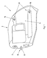
- Fig. 1 to 3 includes a lighting device 1, which is intended for use in a motor vehicle, in particular in a passenger car, at least one lamp housing 2.
- the viewing direction in Fig. 1 is chosen so that the housing 2 a back 3 and a bottom 4 can be seen.
- Fig. 3 a front side 5 of the housing 2, which may contain a window or is designed as a window.
- the luminaire housing 2 accommodates illuminants, such as, for example, headlights, parking lights and turn signals. Through the respective window, the light generated by the bulbs can emerge from the luminaire housing 2.
- the lighting device 1 comprises a housing receptacle 6. This is, for example, on a vehicle body or according to Fig. 3 formed on affybeplankung 7.
- the lamp housing 2 is inserted into the housing receptacle 6.
- a plurality of coupling points are provided, namely an inner coupling point 8 and two outer coupling points 9.
- the inner coupling point 8 is arranged on the back 3 of the housing 2 and is thus located at one of the window 5 (front 5) of the housing 2 side facing away from the housing 2.
- the inner coupling point 8 is designed as a ball joint.
- the outer coupling points 9 are each designed as a sliding guide.
- the outer coupling points 9 are arranged at a distance from the inner coupling point 8. Furthermore, the two outer coupling points 9 are also arranged spaced from each other. In addition, in principle, more than two outer coupling points 9 may be provided. However, preference is given to the variant shown here, in which exactly two outer coupling points 9 are provided.
- the inner coupling point 8 has to realize the ball joint on a ball head 10 and a ball socket 11.
- Ball head 10 and ball socket 11 are in an in Fig. 2 indicated by an arrow mounting direction 12 for the realization of the ball joint inserted into one another. This mated condition is in Fig. 3 played.
- the ball head 10 is formed on the housing receptacle 6, while the ball socket 11 is formed on the lamp housing 2. It is clear that In principle, a reverse construction is possible, in which the ball head 10 on the light housing 2 and the ball socket 11 are formed on the housing receptacle 6. Ball head 10 and ball seat 11 act appropriately together so that when plugging a Verclipsung or latching takes place, which ensures a certain withdrawal protection against the mounting direction 12.
- this Verclipsung is achieved in that the ball socket 11 is segmented, wherein the individual segments are resilient in the radial direction resiliently. When inserting the ball head 10, these pan segments are displaced radially. With sufficient insertion depth, the pan segments then spring back and engage behind the ball head 10.
- the ball head 10 or generally the receiving-side component of the inner coupling point 8 is not formed directly on the housing receptacle 6, but on a holding plate 13.
- This holding plate 13 is fixed to a rear wall 14 of the housing receptacle 6, the in the assembled state, the back 3 of the housing 2 faces.
- the housing receptacle 6 may be designed as a sheet-metal shaped part, while the holding plate 13 is made with the receptacle-side part of the inner coupling point 8 made of plastic.
- the outer coupling points 9 are expediently configured identically to one another.
- the respective outer coupling point 9 has a T-bolt 15 and a guide groove 16.
- the guide groove 16 is dimensioned and aligned so that the associated T-bolt 15 in the mounting direction 12 in the guide groove 16 can be inserted or inserted in the assembled state.
- the guide groove 16 and the associated T-bolt 15 are so coordinated that the T-bolt 15 in the assembled state by an in Fig. 3 drawn longitudinal central axis 17 is rotatable, while at the same time is secured transversely to the mounting direction 12 positively in the guide groove 16.
- the respective guide groove 16 in the mounting direction 12 is open and has C-shaped side portions which engage over the T-section of the T-bolt 15 when the T-bolt 15 is inserted into the guide groove 16.
- the outer coupling points 9 preferably additionally each have a guide surface 18, which is arranged with respect to the mounting direction 12 in front of the respective longitudinal groove 16.
- On this guide surface 18 of the associated T-bolt 15 is turned off with its T-section for the assembly process.
- the guide surface 18 adjoins the open side of the respective guide groove 16 and forms a planar or ramp-shaped guide to the open side of the respective guide groove 16.
- At least one of the guide surfaces 18 may additionally have an upwardly projecting edge, which has a centering effect for the respective T-bolt 15 unfolded to facilitate the insertion of the T-bolts 15 in the guide grooves 16.
- the T-bolts 15 are formed on the lamp housing 2, specifically on the underside 4.
- the guide grooves 16 are formed on the housing receptacle 6 and on a retaining strip 19 of the housing receptacle 6.
- the guide surfaces 18 are then formed on the housing receptacle 6 and on the retaining strip 19.
- the T-bolts 15 are formed on the housing receptacle 6 and on the retaining strip 19, while the guide grooves 16 are optionally formed with the guide surfaces 18 on the lamp housing 2.
- the variant shown here is preferred.
- the inner coupling point 8 is thus receiving side directly on the housing receptacle 6, namely on a wall portion 14, here the rear wall 14, the housing receptacle 4 formed while the outer coupling points 9 are formed only indirectly on the housing receptacle 6, namely
- This can be positioned relative to the other receptacle 6 and in particular can form a separate component with respect to the wall part 14 or with respect to the rest of the housing receptacle 6.
- the retaining strip 19 is attached to the remaining housing receptacle 6.
- Corresponding attachment points are in Fig. 2 denoted by 20.
- it can also be provided not to fasten the retaining strip 19 to the remaining housing receptacle 6, but directly to the vehicle body or to a vehicle planking.
- the retaining strip 19 is expediently arranged relative to the wall part 14 or relative to the other housing receptacle 6 adjustable. This is achieved, for example, by means of correspondingly dimensioned opening pairs in the region of the fastening points 20, which make possible a setting clearance transversely to the mounting direction 12. For example, intersecting slots may be provided or the like.
- the ball joint of the inner coupling point 8 defines a center about which the lamp housing 2 is spatially movable.
- the sliding guides of the outer coupling points 9 can follow horizontal, transverse to the mounting direction 12 adjusting movements of the retaining strip 19 due to the rotation of the T-bolts 15 about their longitudinal central axes 17 in the guide grooves 16. Further, the outer Coupling 9 follow vertical adjustment movements of the retaining strip 19 transverse to the mounting direction 12, which is realized by a corresponding longitudinal clearance parallel to the longitudinal center axes 17 between the T-bolts 15 and the guide grooves 16.
- the simplified adjustment of the lamp housing 2 relative to the adjacent skins 7 results in a corresponding simplification of assembly or an improved joint pattern for the respective vehicle.
- the lighting device 1 may be associated with a vehicle side, so that at least two such lighting devices 1 are present on the vehicle, namely on each side of the vehicle at least one.
- the lighting device 1 can be designed as a front lighting device or as a rear lighting device. In principle, therefore, a vehicle equipped with it can have four such lighting devices 1.
Abstract
Description
Die vorliegende Erfindung betrifft eine Beleuchtungseinrichtung für ein Kraftfahrzeug, insbesondere Personenkraftwagen, mit den Merkmalen des Oberbegriffs des Anspruchs 1.The present invention relates to a lighting device for a motor vehicle, in particular passenger cars, having the features of the preamble of claim 1.
Aus der
Ein Fahrzeug weist in seiner Außenhaut Fugen auf, die dort entstehen, wo separat hergestellte und separat montierte Beplankungsteile aneinander grenzen. Qualitativ hochwertige Fahrzeuge zeichnen sich insbesondere durch ein exaktes Fugenbild aus. Die Fugen zeigen dann insbesondere über ihre Länge eine konstante Fugenbreite. Gerade im Bereich von Beleuchtungseinrichtungen ist es häufig problematisch, ein exaktes Fugenbild zu realisieren, beispielsweise zwischen dem Leuchtengehäuse und Beplankungsteilen, welche ein Fenster des Leuchtengehäuses einfassen.A vehicle has in its outer skin joints that arise where separately manufactured and separately mounted planking parts abut each other. High-quality vehicles are characterized in particular by an exact joint pattern. The joints then show a constant joint width, especially over their length. Especially in the field of lighting devices, it is often problematic to realize an exact joint pattern, for example between the lamp housing and Plankungsteilen which surround a window of the lamp housing.
Die vorliegende Erfindung beschäftigt sich mit dem Problem, für eine Beleuchtungseinrichtung der eingangs genannten Art eine verbesserte Ausführungsform anzugeben, die sich insbesondere dadurch auszeichnet, dass sie die Herstellung eines gewünschten Fugenbilds vereinfacht.The present invention is concerned with the problem of providing for an illumination device of the type mentioned in an improved embodiment, which is particularly characterized in that it simplifies the production of a desired joint image.
Dieses Problem wird erfindungsgemäß durch den Gegenstand des unabhängigen Anspruchs gelöst. Vorteilhafte Ausführungsformen sind Gegenstand der abhängigen Ansprüche.This problem is solved according to the invention by the subject matter of the independent claim. Advantageous embodiments are the subject of the dependent claims.
Die Erfindung beruht auf dem allgemeinen Gedanken, das Leuchtengehäuse innen über ein Kugelgelenk zu lagern und beabstandet davon über wenigstens zwei Schiebeführungen zu positionieren. Durch die vorgeschlagene Bauweise ist das Leuchtengehäuse um einen durch das Kugelgelenk definierten Mittelpunkt räumlich beweglich, so dass es insbesondere möglich ist, das Leuchtengehäuse zum Einstellen eines gewünschten Fugenbilds zu justieren.The invention is based on the general idea to store the lamp housing inside via a ball joint and spaced thereof to position over at least two sliding guides. By the proposed construction, the lamp housing is spatially movable about a center defined by the ball joint, so that it is particularly possible to adjust the lamp housing for setting a desired joint image.
Entsprechend einer vorteilhaften Ausführungsform kann die innere Kopplungsstelle aufnahmeseitig an einem Wandungsteil der Gehäuseaufnahme ausgebildet sein, während die äußeren Kopplungsstellen aufnahmeseitig jeweils an einer Halteleiste der Gehäuseaufnahme ausgebildet sind, wobei diese Halteleiste bezüglich des besagten Wandungsteils verstellbar ist bzw. ein separates Bauteil bildet. Mit Hilfe einer derartigen, insbesondere separaten, Halteleiste kann die Relativlage der äußeren Kopplungsstellen bezüglich der inneren Kopplungsstelle verändert werden, was eine Justierung des Leuchtengehäuses für den Fall ermöglicht, dass die durch Schiebeführungen gebildeten äußeren Kopplungsstellen zur Verbesserung ihrer Haltewirkung so ausgestaltet sind, dass sie selbst räumliche Bewegungen um den Mittelpunkt der inneren Kopplungsstelle nicht oder nur sehr begrenzt zulassen.According to an advantageous embodiment, the inner coupling point can be formed on the receiving side on a wall part of the housing receptacle, while the outer coupling points are each formed on the receiving side on a retaining strip of the housing receptacle, said retaining strip is adjustable with respect to the said wall part or forms a separate component. With the help of such, in particular separate, retaining strip, the relative position of the outer coupling points can be changed with respect to the inner coupling point, which allows an adjustment of the lamp housing in the event that the outer coupling points formed by sliding guides to improve their holding effect are designed so that they themselves spatial movements around the center of the inner coupling point not or only very limited.
Dementsprechend kann die Halteleiste bei einer vorteilhaften Weiterbildung relativ zum Wandungsteil justierbar angeordnet sein, so dass durch Justieren der Relativlage der Halteleiste ein Spaltmaß zwischen Leuchtengehäuse und Fahrzeugkarosserie bzw. Fahrzeugbeplankung einstellbar ist. Auf diese Weise wird eine besonders einfache Möglichkeit zum Justieren des Fugenbilds bereitgestellt.Accordingly, the retaining strip can be arranged adjustable in an advantageous development relative to the wall part, so that by adjusting the relative position of the retaining strip, a gap between the lamp housing and vehicle body or Fahrzeugbeplankung is adjustable. In this way, a particularly simple way to adjust the joint image is provided.
Weitere wichtige Merkmale und Vorteile der Erfindung ergeben sich aus den Unteransprüchen, aus den Zeichnungen und aus der zugehörigen Figurenbeschreibung anhand der Zeichnungen.Other important features and advantages of the invention will become apparent from the dependent claims, from the drawings and from the associated figure description with reference to the drawings.
Es versteht sich, dass die vorstehend genannten und die nachstehend noch zu erläuternden Merkmale nicht nur in der jeweils angegebenen Kombination, sondern auch in anderen Kombinationen oder in Alleinstellung verwendbar sind, ohne den Rahmen der vorliegenden Erfindung zu verlassen.It is understood that the features mentioned above and those yet to be explained below can be used not only in the particular combination given, but also in other combinations or in isolation, without departing from the scope of the present invention.
Bevorzugte Ausführungsbeispiele der Erfindung sind in den Zeichnungen dargestellt und werden in der nachfolgenden Beschreibung näher erläutert, wobei sich gleiche Bezugszeichen auf gleiche oder ähnliche oder funktional gleiche Bauteile beziehen.Preferred embodiments of the invention are illustrated in the drawings and will be described in more detail in the following description, wherein like reference numerals refer to the same or similar or functionally identical components.
Es zeigen, jeweils schematisch,
- Fig. 1
- eine perspektivische Ansicht von unten und von hinten eines Leuchtengehäuses,
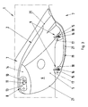
- Fig. 2
- eine perspektivische Ansicht von oben und von vorne einer Gehäuseaufnahme,
- Fig. 3
- eine perspektivische Ansicht von vorne und von oben einer montierten Beleuchtungseinrichtung bei transparent dargestelltem Leuchtengehäuse.
- Fig. 1
- a perspective view from below and from behind a lamp housing,
- Fig. 2
- a perspective view from above and from the front of a housing receptacle,
- Fig. 3
- a perspective view from the front and from the top of a mounted lighting device with transparent light housing.
Entsprechend den
Fahrzeugseitig umfasst die Beleuchtungseinrichtung 1 eine Gehäuseaufnahme 6. Diese ist zum Beispiel an einer Fahrzeugkarosserie oder gemäß
Die innere Kopplungsstelle 8 weist zur Realisierung des Kugelgelenks einen Kugelkopf 10 und eine Kugelpfanne 11 auf. Kugelkopf 10 und Kugelpfanne 11 sind in einer in
Bei der hier gezeigten, bevorzugten Ausführungsform, ist der Kugelkopf 10 bzw. allgemein die aufnahmeseitige Komponente der inneren Kopplungsstelle 8 nicht unmittelbar an der Gehäuseaufnahme 6 ausgebildet, sondern an einer Halteplatte 13. Diese Halteplatte 13 ist an einer Rückwand 14 der Gehäuseaufnahme 6 befestigt, die im montierten Zustand der Rückseite 3 des Gehäuses 2 zugewandt ist. Hierdurch ist es möglich, die aufnahmeseitigen Komponenten der inneren Kopplungsstelle 8, also hier den Kugelkopf 10, separat von der übrigen Gehäuseaufnahme 6 herzustellen. Beispielsweise kann die Gehäuseaufnahme 6 als Blechformteil ausgestaltet sein, während die Halteplatte 13 mit dem aufnahmeseitigen Bestandteil der inneren Kopplungsstelle 8 aus Kunststoff hergestellt ist.In the preferred embodiment shown here, the
Die äußeren Kopplungsstellen 9 sind zueinander zweckmäßig identisch ausgestaltet. Bei der hier gezeigten, bevorzugten Ausführungsform besitzt die jeweilige äußere Kopplungsstelle 9 einen T-Bolzen 15 sowie eine Führungsnut 16. Die Führungsnut 16 ist dabei so dimensioniert und ausgerichtet, dass der zugehörige T-Bolzen 15 in der Montagerichtung 12 in die Führungsnut 16 einsteckbar ist bzw. im montierten Zustand darin eingesteckt ist. Ferner sind die Führungsnut 16 und der zugehörige T-Bolzen 15 so aufeinander abgestimmt, dass der T-Bolzen 15 im montierten Zustand um eine in
Die äußeren Kopplungsstellen 9 besitzen entsprechend der hier vorgestellten Ausführungsform vorzugsweise zusätzlich jeweils eine Führungsfläche 18, die bezüglich der Montagerichtung 12 vor der jeweiligen Längsnut 16 angeordnet ist. Auf dieser Führungsfläche 18 ist der zugehörige T-Bolzen 15 mit seinem T-Abschnitt für den Montagevorgang abstellbar. Die Führungsfläche 18 schließt sich an die offene Seite der jeweiligen Führungsnut 16 an und bildet eine ebene oder rampenförmige Führung zur offenen Seite der jeweiligen Führungsnut 16. Zumindest eine der Führungsflächen 18 kann zusätzlich einen nach oben abstehenden Rand aufweisen, der eine zentrierende Wirkung für den jeweiligen T-Bolzen 15 entfaltet, um das Einführen der T-Bolzen 15 in die Führungsnuten 16 zu erleichtern.The
Bei der hier vorgestellten bevorzugten Ausführungsform sind die T-Bolzen 15 am Leuchtengehäuse 2 ausgebildet, und zwar an der Unterseite 4. Im Unterschied dazu sind die Führungsnuten 16 an der Gehäuseaufnahme 6 bzw. an einer Halteleiste 19 der Gehäuseaufnahme 6 ausgebildet. In diesem Fall sind dann auch die Führungsflächen 18 an der Gehäuseaufnahme 6 bzw. an der Halteleiste 19 ausgebildet. Es ist klar, dass grundsätzlich auch eine umgekehrte Bauweise denkbar ist, bei welcher die T-Bolzen 15 an der Gehäuseaufnahme 6 bzw. an deren Halteleiste 19 ausgebildet sind, während die Führungsnuten 16 gegebenenfalls mit den Führungsflächen 18 am Leuchtengehäuse 2 ausgebildet sind. Bevorzugt wird jedoch die hier gezeigte Variante.In the preferred embodiment presented here, the T-
Gemäß der hier vorgestellten bevorzugten Bauweise ist somit die innere Kopplungsstelle 8 aufnahmeseitig unmittelbar an der Gehäuseaufnahme 6, nämlich an einem Wandungsteil 14, hier der Rückwand 14, der Gehäuseaufnahme 4 ausgebildet, während die äußeren Kopplungsstellen 9 nur mittelbar an der Gehäuseaufnahme 6 ausgebildet sind, nämlich an der Halteleiste 19. Diese ist relativ zur übrigen Aufnahme 6 positionierbar und kann insbesondere ein bezüglich des Wandungsteils 14 bzw. bezüglich der übrigen Gehäuseaufnahme 6 ein separates Bauteil bilden. Im Beispiel ist die Halteleiste 19 an der übrigen Gehäuseaufnahme 6 befestigt. Entsprechende Befestigungsstellen sind in
Die Halteleiste 19 ist zweckmäßig relativ zum Wandungsteil 14 bzw. relativ zur übrigen Gehäuseaufnahme 6 justierbar angeordnet. Erreicht wird dies beispielsweise über entsprechend dimensionierte Öffnungspaarungen im Bereich der Befestigungsstellen 20, die ein Einstellspiel quer zur Montagerichtung 12 ermöglichen. Beispielsweise können sich kreuzende Langlöcher vorgesehen sein oder dergleichen. Durch Justieren der Position der Halteleiste 19 relativ zur übrigen Gehäuseaufnahme 6 ist es möglich, bei zwei Fugen 21, die im montierten Zustand gemäß
Claims (10)
Applications Claiming Priority (1)
| Application Number | Priority Date | Filing Date | Title |
|---|---|---|---|
| DE102008059294A DE102008059294A1 (en) | 2008-11-27 | 2008-11-27 | Lighting device for a motor vehicle |
Publications (2)
| Publication Number | Publication Date |
|---|---|
| EP2192003A1 true EP2192003A1 (en) | 2010-06-02 |
| EP2192003B1 EP2192003B1 (en) | 2020-05-13 |
Family
ID=41682325
Family Applications (1)
| Application Number | Title | Priority Date | Filing Date |
|---|---|---|---|
| EP09008957.4A Active EP2192003B1 (en) | 2008-11-27 | 2009-07-09 | Motor vehicle with a car body and a lighting device |
Country Status (2)
| Country | Link |
|---|---|
| EP (1) | EP2192003B1 (en) |
| DE (1) | DE102008059294A1 (en) |
Cited By (2)
| Publication number | Priority date | Publication date | Assignee | Title |
|---|---|---|---|---|
| DE102020104316B3 (en) * | 2020-02-19 | 2021-06-02 | Dr. Ing. H.C. F. Porsche Aktiengesellschaft | Device for attaching a light strip to a motor vehicle |
| DE102021130828A1 (en) | 2021-11-24 | 2023-05-25 | Bayerische Motoren Werke Aktiengesellschaft | Paneling component for a body of a motor vehicle |
Families Citing this family (2)
| Publication number | Priority date | Publication date | Assignee | Title |
|---|---|---|---|---|
| DE102010007217A1 (en) * | 2010-02-09 | 2011-08-11 | GM Global Technology Operations LLC, ( n. d. Ges. d. Staates Delaware ), Mich. | Assembly module for headlight of motor vehicle, comprises receiving recess for headlight housing, which is accessible in installation condition at motor vehicle from front, against direction of travel |
| DE102012004748A1 (en) | 2012-03-08 | 2013-09-12 | GM Global Technology Operations LLC (n. d. Gesetzen des Staates Delaware) | Device for attaching a light of a motor vehicle to the body thereof |
Citations (5)
| Publication number | Priority date | Publication date | Assignee | Title |
|---|---|---|---|---|
| GB1227418A (en) * | 1967-04-06 | 1971-04-07 | Cibie Projecteurs | Improvements in or relating to a headlamp |
| FR2785242A1 (en) * | 1998-11-02 | 2000-05-05 | Peugeot | Rear lighting cluster for an automobile, comprises a modular construction that enables the lighting cluster to be completely removed from the vehicle |
| DE10234224A1 (en) | 2002-07-27 | 2004-02-05 | Hella-Behr Fahrzeugsysteme Gmbh | Lighting unit and method for fastening a lighting unit |
| DE10243575A1 (en) * | 2002-09-19 | 2004-04-01 | Volkswagen Ag | Motor vehicle headlight mounting assembly, has ball and socket joint and threaded sleeve to allow adjustment of axial position of fastening |
| WO2008101451A1 (en) * | 2007-02-19 | 2008-08-28 | Hbpo Gmbh | Front end module for vehicles |
Family Cites Families (8)
| Publication number | Priority date | Publication date | Assignee | Title |
|---|---|---|---|---|
| JP3229968B2 (en) * | 1990-07-23 | 2001-11-19 | 株式会社パイオラックス | Mounting structure of lamp base for automobile |
| DE4133002C3 (en) * | 1991-10-04 | 1996-02-15 | Bayerische Motoren Werke Ag | Fastening device for a motor vehicle headlight assembly |
| DE4311419C2 (en) * | 1993-04-07 | 1995-09-07 | Porsche Ag | Fixing device for a headlight |
| JP2004351959A (en) * | 2003-05-27 | 2004-12-16 | Nissan Motor Co Ltd | Head lamp attaching structure for automobile |
| DE102005053423B4 (en) * | 2005-11-07 | 2007-07-26 | Decoma (Germany) Gmbh | Headlight fixture |
| FR2901202B1 (en) * | 2006-05-22 | 2009-06-05 | Renault Sport Technologies Soc | MOTOR VEHICLE PROJECTOR AND MOTOR VEHICLE COMPRISING SUCH A PROJECTOR |
| DE102006026255A1 (en) * | 2006-06-02 | 2007-12-06 | Peguform Gmbh | bumper module |
| DE102006058857A1 (en) * | 2006-12-13 | 2008-06-19 | Volkswagen Ag | End module, in particular front end module for a vehicle, and method for mounting an end module to a vehicle body |
-
2008
- 2008-11-27 DE DE102008059294A patent/DE102008059294A1/en not_active Withdrawn
-
2009
- 2009-07-09 EP EP09008957.4A patent/EP2192003B1/en active Active
Patent Citations (5)
| Publication number | Priority date | Publication date | Assignee | Title |
|---|---|---|---|---|
| GB1227418A (en) * | 1967-04-06 | 1971-04-07 | Cibie Projecteurs | Improvements in or relating to a headlamp |
| FR2785242A1 (en) * | 1998-11-02 | 2000-05-05 | Peugeot | Rear lighting cluster for an automobile, comprises a modular construction that enables the lighting cluster to be completely removed from the vehicle |
| DE10234224A1 (en) | 2002-07-27 | 2004-02-05 | Hella-Behr Fahrzeugsysteme Gmbh | Lighting unit and method for fastening a lighting unit |
| DE10243575A1 (en) * | 2002-09-19 | 2004-04-01 | Volkswagen Ag | Motor vehicle headlight mounting assembly, has ball and socket joint and threaded sleeve to allow adjustment of axial position of fastening |
| WO2008101451A1 (en) * | 2007-02-19 | 2008-08-28 | Hbpo Gmbh | Front end module for vehicles |
Cited By (3)
| Publication number | Priority date | Publication date | Assignee | Title |
|---|---|---|---|---|
| DE102020104316B3 (en) * | 2020-02-19 | 2021-06-02 | Dr. Ing. H.C. F. Porsche Aktiengesellschaft | Device for attaching a light strip to a motor vehicle |
| US11592049B2 (en) | 2020-02-19 | 2023-02-28 | Dr. Ing. H.C. F. Porsche Aktiengesellschaft | Device for fastening a light strip to a motor vehicle |
| DE102021130828A1 (en) | 2021-11-24 | 2023-05-25 | Bayerische Motoren Werke Aktiengesellschaft | Paneling component for a body of a motor vehicle |
Also Published As
| Publication number | Publication date |
|---|---|
| EP2192003B1 (en) | 2020-05-13 |
| DE102008059294A1 (en) | 2010-06-02 |
Similar Documents
| Publication | Publication Date | Title |
|---|---|---|
| DE102012009173A1 (en) | Tolerance compensating device for fastening e.g. roof lath at roof of motor car, has adjustment device axially held at rivet sleeve that is connected to structure or component through aperture of roof structure | |
| DE102009015463A1 (en) | Tilt adjustment device for a vehicle seat | |
| DE102011009211A1 (en) | Clip device for fastening seat shell to seat frame of vehicle seat for motor vehicle, particularly for sliding or rotary mounting, is provided with clip units, where connecting element is provided for connecting two clip units | |
| WO2007131830A1 (en) | Device and method for fastening a wiper motor to a wiper linkage | |
| EP2192003B1 (en) | Motor vehicle with a car body and a lighting device | |
| DE102014014541A1 (en) | Method and arrangement for adjusting a door inner lining on a motor vehicle | |
| DE102008038842A1 (en) | Bumper arrangement for motor vehicle, particularly for passenger car, has bumper lining adjacent to light unit, where bumper lining is fixed directly by back-gripped connection or locking connection at base carrier of light unit | |
| DE102015105913A1 (en) | Motor vehicle door with an exterior rearview mirror | |
| DE202011005654U1 (en) | Fastening element for connecting two components | |
| DE102006019576B4 (en) | Steering device for vehicles and method for mounting a bearing assembly | |
| DE102016117057A1 (en) | Door frame of a motor vehicle | |
| DE102015219853A1 (en) | wiper system | |
| DE102006053263A1 (en) | Sleeve gasket for leading through steering column and for sealing passage in vehicle partition between engine compartment and passenger compartment, has mounting medium, which has rest element formed in one-piece with sleeve gasket | |
| DE102015222890B4 (en) | Compatible door hinge for vehicles | |
| DE102006053265A1 (en) | Sealing arrangement for sealing a passage opening and mounting method | |
| DE102013010490A1 (en) | Front end of a motor vehicle | |
| DE102018209343B3 (en) | motor vehicle | |
| DE102012019092A1 (en) | Front module for use in e.g. front end of passenger car, has holder holding crash boxes at assembly carrier and allowing tolerance compensation in vehicle transverse direction, where crash boxes are fastened at longitudinal beam of vehicle | |
| DE102010015340B4 (en) | Airbag module | |
| DE102011112049B4 (en) | seat belt buckle assembly | |
| DE102009026727A1 (en) | Fastening device for releasable connection of body trim e.g. decorative strip, with base support i.e. door, of motor vehicle, has latching element arranged at body trim, and locking element for supporting connection of trim and base support | |
| DE102006019574A1 (en) | Steering device for vehicles | |
| DE10217160B4 (en) | Radiator grill bumper assembly | |
| DE102019110082A1 (en) | Wind deflector for a windshield wiper system of a motor vehicle | |
| DE102012024275A1 (en) | Fastening device for fastening mechanical, electrical and / or electronic modules |
Legal Events
| Date | Code | Title | Description |
|---|---|---|---|
| PUAI | Public reference made under article 153(3) epc to a published international application that has entered the european phase |
Free format text: ORIGINAL CODE: 0009012 |
|
| AK | Designated contracting states |
Kind code of ref document: A1 Designated state(s): AT BE BG CH CY CZ DE DK EE ES FI FR GB GR HR HU IE IS IT LI LT LU LV MC MK MT NL NO PL PT RO SE SI SK SM TR |
|
| AX | Request for extension of the european patent |
Extension state: AL BA RS |
|
| 17P | Request for examination filed |
Effective date: 20101202 |
|
| 17Q | First examination report despatched |
Effective date: 20110111 |
|
| STAA | Information on the status of an ep patent application or granted ep patent |
Free format text: STATUS: EXAMINATION IS IN PROGRESS |
|
| GRAP | Despatch of communication of intention to grant a patent |
Free format text: ORIGINAL CODE: EPIDOSNIGR1 |
|
| STAA | Information on the status of an ep patent application or granted ep patent |
Free format text: STATUS: GRANT OF PATENT IS INTENDED |
|
| INTG | Intention to grant announced |
Effective date: 20191202 |
|
| GRAS | Grant fee paid |
Free format text: ORIGINAL CODE: EPIDOSNIGR3 |
|
| GRAA | (expected) grant |
Free format text: ORIGINAL CODE: 0009210 |
|
| STAA | Information on the status of an ep patent application or granted ep patent |
Free format text: STATUS: THE PATENT HAS BEEN GRANTED |
|
| AK | Designated contracting states |
Kind code of ref document: B1 Designated state(s): AT BE BG CH CY CZ DE DK EE ES FI FR GB GR HR HU IE IS IT LI LT LU LV MC MK MT NL NO PL PT RO SE SI SK SM TR |
|
| REG | Reference to a national code |
Ref country code: GB Ref legal event code: FG4D Free format text: NOT ENGLISH |
|
| REG | Reference to a national code |
Ref country code: CH Ref legal event code: EP |
|
| REG | Reference to a national code |
Ref country code: DE Ref legal event code: R096 Ref document number: 502009016194 Country of ref document: DE |
|
| REG | Reference to a national code |
Ref country code: AT Ref legal event code: REF Ref document number: 1269838 Country of ref document: AT Kind code of ref document: T Effective date: 20200615 |
|
| REG | Reference to a national code |
Ref country code: LT Ref legal event code: MG4D |
|
| REG | Reference to a national code |
Ref country code: NL Ref legal event code: MP Effective date: 20200513 |
|
| PG25 | Lapsed in a contracting state [announced via postgrant information from national office to epo] |
Ref country code: GR Free format text: LAPSE BECAUSE OF FAILURE TO SUBMIT A TRANSLATION OF THE DESCRIPTION OR TO PAY THE FEE WITHIN THE PRESCRIBED TIME-LIMIT Effective date: 20200814 Ref country code: NO Free format text: LAPSE BECAUSE OF FAILURE TO SUBMIT A TRANSLATION OF THE DESCRIPTION OR TO PAY THE FEE WITHIN THE PRESCRIBED TIME-LIMIT Effective date: 20200813 Ref country code: IS Free format text: LAPSE BECAUSE OF FAILURE TO SUBMIT A TRANSLATION OF THE DESCRIPTION OR TO PAY THE FEE WITHIN THE PRESCRIBED TIME-LIMIT Effective date: 20200913 Ref country code: PT Free format text: LAPSE BECAUSE OF FAILURE TO SUBMIT A TRANSLATION OF THE DESCRIPTION OR TO PAY THE FEE WITHIN THE PRESCRIBED TIME-LIMIT Effective date: 20200914 Ref country code: FI Free format text: LAPSE BECAUSE OF FAILURE TO SUBMIT A TRANSLATION OF THE DESCRIPTION OR TO PAY THE FEE WITHIN THE PRESCRIBED TIME-LIMIT Effective date: 20200513 Ref country code: SE Free format text: LAPSE BECAUSE OF FAILURE TO SUBMIT A TRANSLATION OF THE DESCRIPTION OR TO PAY THE FEE WITHIN THE PRESCRIBED TIME-LIMIT Effective date: 20200513 Ref country code: LT Free format text: LAPSE BECAUSE OF FAILURE TO SUBMIT A TRANSLATION OF THE DESCRIPTION OR TO PAY THE FEE WITHIN THE PRESCRIBED TIME-LIMIT Effective date: 20200513 |
|
| PGFP | Annual fee paid to national office [announced via postgrant information from national office to epo] |
Ref country code: DE Payment date: 20200706 Year of fee payment: 12 |
|
| PG25 | Lapsed in a contracting state [announced via postgrant information from national office to epo] |
Ref country code: HR Free format text: LAPSE BECAUSE OF FAILURE TO SUBMIT A TRANSLATION OF THE DESCRIPTION OR TO PAY THE FEE WITHIN THE PRESCRIBED TIME-LIMIT Effective date: 20200513 Ref country code: BG Free format text: LAPSE BECAUSE OF FAILURE TO SUBMIT A TRANSLATION OF THE DESCRIPTION OR TO PAY THE FEE WITHIN THE PRESCRIBED TIME-LIMIT Effective date: 20200813 Ref country code: LV Free format text: LAPSE BECAUSE OF FAILURE TO SUBMIT A TRANSLATION OF THE DESCRIPTION OR TO PAY THE FEE WITHIN THE PRESCRIBED TIME-LIMIT Effective date: 20200513 |
|
| PG25 | Lapsed in a contracting state [announced via postgrant information from national office to epo] |
Ref country code: NL Free format text: LAPSE BECAUSE OF FAILURE TO SUBMIT A TRANSLATION OF THE DESCRIPTION OR TO PAY THE FEE WITHIN THE PRESCRIBED TIME-LIMIT Effective date: 20200513 |
|
| PG25 | Lapsed in a contracting state [announced via postgrant information from national office to epo] |
Ref country code: ES Free format text: LAPSE BECAUSE OF FAILURE TO SUBMIT A TRANSLATION OF THE DESCRIPTION OR TO PAY THE FEE WITHIN THE PRESCRIBED TIME-LIMIT Effective date: 20200513 Ref country code: DK Free format text: LAPSE BECAUSE OF FAILURE TO SUBMIT A TRANSLATION OF THE DESCRIPTION OR TO PAY THE FEE WITHIN THE PRESCRIBED TIME-LIMIT Effective date: 20200513 Ref country code: SM Free format text: LAPSE BECAUSE OF FAILURE TO SUBMIT A TRANSLATION OF THE DESCRIPTION OR TO PAY THE FEE WITHIN THE PRESCRIBED TIME-LIMIT Effective date: 20200513 Ref country code: EE Free format text: LAPSE BECAUSE OF FAILURE TO SUBMIT A TRANSLATION OF THE DESCRIPTION OR TO PAY THE FEE WITHIN THE PRESCRIBED TIME-LIMIT Effective date: 20200513 Ref country code: IT Free format text: LAPSE BECAUSE OF FAILURE TO SUBMIT A TRANSLATION OF THE DESCRIPTION OR TO PAY THE FEE WITHIN THE PRESCRIBED TIME-LIMIT Effective date: 20200513 Ref country code: CZ Free format text: LAPSE BECAUSE OF FAILURE TO SUBMIT A TRANSLATION OF THE DESCRIPTION OR TO PAY THE FEE WITHIN THE PRESCRIBED TIME-LIMIT Effective date: 20200513 Ref country code: RO Free format text: LAPSE BECAUSE OF FAILURE TO SUBMIT A TRANSLATION OF THE DESCRIPTION OR TO PAY THE FEE WITHIN THE PRESCRIBED TIME-LIMIT Effective date: 20200513 |
|
| REG | Reference to a national code |
Ref country code: DE Ref legal event code: R097 Ref document number: 502009016194 Country of ref document: DE |
|
| PG25 | Lapsed in a contracting state [announced via postgrant information from national office to epo] |
Ref country code: PL Free format text: LAPSE BECAUSE OF FAILURE TO SUBMIT A TRANSLATION OF THE DESCRIPTION OR TO PAY THE FEE WITHIN THE PRESCRIBED TIME-LIMIT Effective date: 20200513 Ref country code: MC Free format text: LAPSE BECAUSE OF FAILURE TO SUBMIT A TRANSLATION OF THE DESCRIPTION OR TO PAY THE FEE WITHIN THE PRESCRIBED TIME-LIMIT Effective date: 20200513 Ref country code: SK Free format text: LAPSE BECAUSE OF FAILURE TO SUBMIT A TRANSLATION OF THE DESCRIPTION OR TO PAY THE FEE WITHIN THE PRESCRIBED TIME-LIMIT Effective date: 20200513 |
|
| REG | Reference to a national code |
Ref country code: CH Ref legal event code: PL |
|
| PLBE | No opposition filed within time limit |
Free format text: ORIGINAL CODE: 0009261 |
|
| STAA | Information on the status of an ep patent application or granted ep patent |
Free format text: STATUS: NO OPPOSITION FILED WITHIN TIME LIMIT |
|
| 26N | No opposition filed |
Effective date: 20210216 |
|
| GBPC | Gb: european patent ceased through non-payment of renewal fee |
Effective date: 20200813 |
|
| REG | Reference to a national code |
Ref country code: BE Ref legal event code: MM Effective date: 20200731 |
|
| PG25 | Lapsed in a contracting state [announced via postgrant information from national office to epo] |
Ref country code: LU Free format text: LAPSE BECAUSE OF NON-PAYMENT OF DUE FEES Effective date: 20200709 Ref country code: LI Free format text: LAPSE BECAUSE OF NON-PAYMENT OF DUE FEES Effective date: 20200731 Ref country code: CH Free format text: LAPSE BECAUSE OF NON-PAYMENT OF DUE FEES Effective date: 20200731 |
|
| PG25 | Lapsed in a contracting state [announced via postgrant information from national office to epo] |
Ref country code: BE Free format text: LAPSE BECAUSE OF NON-PAYMENT OF DUE FEES Effective date: 20200731 Ref country code: SI Free format text: LAPSE BECAUSE OF FAILURE TO SUBMIT A TRANSLATION OF THE DESCRIPTION OR TO PAY THE FEE WITHIN THE PRESCRIBED TIME-LIMIT Effective date: 20200513 |
|
| PG25 | Lapsed in a contracting state [announced via postgrant information from national office to epo] |
Ref country code: IE Free format text: LAPSE BECAUSE OF NON-PAYMENT OF DUE FEES Effective date: 20200709 Ref country code: GB Free format text: LAPSE BECAUSE OF NON-PAYMENT OF DUE FEES Effective date: 20200813 |
|
| REG | Reference to a national code |
Ref country code: AT Ref legal event code: MM01 Ref document number: 1269838 Country of ref document: AT Kind code of ref document: T Effective date: 20200709 |
|
| PG25 | Lapsed in a contracting state [announced via postgrant information from national office to epo] |
Ref country code: AT Free format text: LAPSE BECAUSE OF NON-PAYMENT OF DUE FEES Effective date: 20200709 |
|
| REG | Reference to a national code |
Ref country code: DE Ref legal event code: R119 Ref document number: 502009016194 Country of ref document: DE |
|
| PG25 | Lapsed in a contracting state [announced via postgrant information from national office to epo] |
Ref country code: DE Free format text: LAPSE BECAUSE OF NON-PAYMENT OF DUE FEES Effective date: 20220201 |
|
| PG25 | Lapsed in a contracting state [announced via postgrant information from national office to epo] |
Ref country code: TR Free format text: LAPSE BECAUSE OF FAILURE TO SUBMIT A TRANSLATION OF THE DESCRIPTION OR TO PAY THE FEE WITHIN THE PRESCRIBED TIME-LIMIT Effective date: 20200513 Ref country code: MT Free format text: LAPSE BECAUSE OF FAILURE TO SUBMIT A TRANSLATION OF THE DESCRIPTION OR TO PAY THE FEE WITHIN THE PRESCRIBED TIME-LIMIT Effective date: 20200513 Ref country code: CY Free format text: LAPSE BECAUSE OF FAILURE TO SUBMIT A TRANSLATION OF THE DESCRIPTION OR TO PAY THE FEE WITHIN THE PRESCRIBED TIME-LIMIT Effective date: 20200513 |
|
| PG25 | Lapsed in a contracting state [announced via postgrant information from national office to epo] |
Ref country code: MK Free format text: LAPSE BECAUSE OF FAILURE TO SUBMIT A TRANSLATION OF THE DESCRIPTION OR TO PAY THE FEE WITHIN THE PRESCRIBED TIME-LIMIT Effective date: 20200513 |
|
| PGFP | Annual fee paid to national office [announced via postgrant information from national office to epo] |
Ref country code: FR Payment date: 20230725 Year of fee payment: 15 |