EP2190515B9 - Medizinische katheteranordnung mit biegbarem zugring und vorrichtung zur arretierung einer distalen spitze - Google Patents
Medizinische katheteranordnung mit biegbarem zugring und vorrichtung zur arretierung einer distalen spitze Download PDFInfo
- Publication number
- EP2190515B9 EP2190515B9 EP08865610.3A EP08865610A EP2190515B9 EP 2190515 B9 EP2190515 B9 EP 2190515B9 EP 08865610 A EP08865610 A EP 08865610A EP 2190515 B9 EP2190515 B9 EP 2190515B9
- Authority
- EP
- European Patent Office
- Prior art keywords
- pull ring
- catheter assembly
- pull
- shaft
- tip
- Prior art date
- Legal status (The legal status is an assumption and is not a legal conclusion. Google has not performed a legal analysis and makes no representation as to the accuracy of the status listed.)
- Active
Links
- 238000002679 ablation Methods 0.000 claims description 26
- 239000012530 fluid Substances 0.000 claims description 24
- 230000006835 compression Effects 0.000 claims description 10
- 238000007906 compression Methods 0.000 claims description 10
- 238000005452 bending Methods 0.000 claims description 2
- 239000011435 rock Substances 0.000 claims description 2
- 230000000712 assembly Effects 0.000 description 9
- 238000000429 assembly Methods 0.000 description 9
- 238000003745 diagnosis Methods 0.000 description 2
- BASFCYQUMIYNBI-UHFFFAOYSA-N platinum Chemical compound [Pt] BASFCYQUMIYNBI-UHFFFAOYSA-N 0.000 description 2
- 230000005856 abnormality Effects 0.000 description 1
- 239000000853 adhesive Substances 0.000 description 1
- 230000001070 adhesive effect Effects 0.000 description 1
- 210000001367 artery Anatomy 0.000 description 1
- 230000002457 bidirectional effect Effects 0.000 description 1
- 230000001010 compromised effect Effects 0.000 description 1
- 238000010276 construction Methods 0.000 description 1
- 238000002001 electrophysiology Methods 0.000 description 1
- 230000007831 electrophysiology Effects 0.000 description 1
- 230000007257 malfunction Effects 0.000 description 1
- 238000013507 mapping Methods 0.000 description 1
- 239000000463 material Substances 0.000 description 1
- 238000000034 method Methods 0.000 description 1
- 230000002107 myocardial effect Effects 0.000 description 1
- 230000037361 pathway Effects 0.000 description 1
- 229910052697 platinum Inorganic materials 0.000 description 1
- 238000000926 separation method Methods 0.000 description 1
- 229910000679 solder Inorganic materials 0.000 description 1
- 210000003462 vein Anatomy 0.000 description 1
Images


Classifications
-
- A—HUMAN NECESSITIES
- A61—MEDICAL OR VETERINARY SCIENCE; HYGIENE
- A61M—DEVICES FOR INTRODUCING MEDIA INTO, OR ONTO, THE BODY; DEVICES FOR TRANSDUCING BODY MEDIA OR FOR TAKING MEDIA FROM THE BODY; DEVICES FOR PRODUCING OR ENDING SLEEP OR STUPOR
- A61M25/00—Catheters; Hollow probes
- A61M25/01—Introducing, guiding, advancing, emplacing or holding catheters
- A61M25/0105—Steering means as part of the catheter or advancing means; Markers for positioning
- A61M25/0133—Tip steering devices
- A61M25/0147—Tip steering devices with movable mechanical means, e.g. pull wires
-
- A—HUMAN NECESSITIES
- A61—MEDICAL OR VETERINARY SCIENCE; HYGIENE
- A61B—DIAGNOSIS; SURGERY; IDENTIFICATION
- A61B18/00—Surgical instruments, devices or methods for transferring non-mechanical forms of energy to or from the body
- A61B18/04—Surgical instruments, devices or methods for transferring non-mechanical forms of energy to or from the body by heating
- A61B18/12—Surgical instruments, devices or methods for transferring non-mechanical forms of energy to or from the body by heating by passing a current through the tissue to be heated, e.g. high-frequency current
- A61B18/14—Probes or electrodes therefor
- A61B18/1492—Probes or electrodes therefor having a flexible, catheter-like structure, e.g. for heart ablation
-
- A—HUMAN NECESSITIES
- A61—MEDICAL OR VETERINARY SCIENCE; HYGIENE
- A61B—DIAGNOSIS; SURGERY; IDENTIFICATION
- A61B17/00—Surgical instruments, devices or methods, e.g. tourniquets
- A61B17/00234—Surgical instruments, devices or methods, e.g. tourniquets for minimally invasive surgery
- A61B2017/00292—Surgical instruments, devices or methods, e.g. tourniquets for minimally invasive surgery mounted on or guided by flexible, e.g. catheter-like, means
- A61B2017/003—Steerable
-
- A—HUMAN NECESSITIES
- A61—MEDICAL OR VETERINARY SCIENCE; HYGIENE
- A61B—DIAGNOSIS; SURGERY; IDENTIFICATION
- A61B18/00—Surgical instruments, devices or methods for transferring non-mechanical forms of energy to or from the body
- A61B18/04—Surgical instruments, devices or methods for transferring non-mechanical forms of energy to or from the body by heating
- A61B18/12—Surgical instruments, devices or methods for transferring non-mechanical forms of energy to or from the body by heating by passing a current through the tissue to be heated, e.g. high-frequency current
- A61B18/14—Probes or electrodes therefor
- A61B2018/1472—Probes or electrodes therefor for use with liquid electrolyte, e.g. virtual electrodes
-
- A—HUMAN NECESSITIES
- A61—MEDICAL OR VETERINARY SCIENCE; HYGIENE
- A61M—DEVICES FOR INTRODUCING MEDIA INTO, OR ONTO, THE BODY; DEVICES FOR TRANSDUCING BODY MEDIA OR FOR TAKING MEDIA FROM THE BODY; DEVICES FOR PRODUCING OR ENDING SLEEP OR STUPOR
- A61M25/00—Catheters; Hollow probes
- A61M25/01—Introducing, guiding, advancing, emplacing or holding catheters
- A61M25/0105—Steering means as part of the catheter or advancing means; Markers for positioning
- A61M25/0133—Tip steering devices
- A61M25/0147—Tip steering devices with movable mechanical means, e.g. pull wires
- A61M2025/015—Details of the distal fixation of the movable mechanical means
Definitions
- the present invention relates to medical catheter assemblies, and in particular to medical catheter assemblies which utilize a deflection pull ring adjacent a distal tip at the distal end of the catheter shaft to bend the deflectable catheter shaft and move the distal tip in a desired direction.
- Medical catheter assemblies used in the diagnosis or treatment of various medical abnormalities are in common use in medical facilities throughout the world. They generally include a deflectable catheter shaft that can be inserted in and extended along a suitable vein or artery of person being diagnosed or treated to a desired site; a handle actuator which supports a proximal end of the catheter shaft; a distal tip which is connected to the distal end of the catheter shaft and which includes a specialized tip element for the appropriate diagnosis or treatment; and a pull ring assembly which includes a pull ring near the distal end of the catheter shaft and pull wires which extend from the pull ring through the catheter shaft back to the handle actuator for tilting or rocking the pull ring upon manual operation of the handle actuator and consequential pulling of the pull wires, i.e., for deflecting a distal end portion of the catheter shaft with distal tip in a desired direction.
- Ablation catheter assemblies are a category of medical catheter assembly used to ablate tissue, e.g., in the treatment of heart malfunctions. They can be irrigated (discharge ablation fluid in addition to ablation energy) or non-irrigated (discharge of ablation energy but not fluid).
- the distal tip will include a tip electrode as the specialized tip element and an energy source will be connected to their handle actuator to supply energy to the tip electrode.
- a fluid manifold is attached to, or is one-piece with, the tip electrode, and a fluid source is attached to their handle actuator to supply ablation fluid thereto.
- the distal tip can include a mounting shaft which cooperates with the distal end of the adjacent deflectable catheter shaft for connection thereto.
- EP 1 205 208 A1 discloses a deflectable catheter having a handle that can be modified for unidirectional or multidirectional deflection.
- the pull wire is anchored in the distal end of the catheter body.
- the catheter comprises a plurality of pull wires and a plurality of corresponding pull wire anchors.
- EP 0 982 047 A2 discloses a bidirectional steerable catheter comprising a catheter body, a tip section and a control handle.
- US 6,926,669 B 1 discloses a steerable electrophysiology catheter for use in mapping and/or ablation of accessory pathways in myocardial tissue of the heart wall and methods of use thereof.
- WO 97/29801 discloses a reduced stiffness, bidirectionally deflecting catheter assembly including a handle and a flexible catheter shaft with a tip section secured to its distal end.
- the tip section has a radially offset, longitudinally extending core wire lumen through which a tapered core wire, extending from a core wire manipulator on the handle, passes.
- the core wire manipulator can be moved in two different directions to pull or push on the core wire to cause the tip section to deflect axially in opposite directions in the same plane.
- the ends of the core wire are non-rotatably secured to the handle and the tip section so that rotating the handle about its axis causes the tip section to deflect laterally due to torsional forces exerted on the tip section by both the catheter shaft and the core wire.
- the taper on the core wire determines the size and shape of the curved tip section when the tip is axially deflected.
- the distal tip is constructed to include guide channels for the pull wires of the pull wire assembly such that the pull wires will initially extend from the pull ring to the which they are attached towards the tip element (in the case of an irrigated or non-irrigated ablation catheter assembly a tip electrode), and then loop back toward and through the catheter shaft via the guides channels to the handle actuator.
- Such a construction results in the pull ring of the pull ring assembly being moved towards the tip element with operation (pulling) of the pull wires. It also results in dissipated (reduced) forces applied to the braze or weld connecting the pull wires to the pull ring such that failure of the pull ring assembly will only occur near the tensile stress limit of the pull wires themselves.
- Fig. 1 shows an irrigated ablation catheter system 10 according to a preferred embodiment of the present invention. It includes an irrigated ablation catheter assembly 12 connected to an energy source 130 and a fluid source 140.
- the irrigated ablation catheter assembly 12 includes a catheter 20, a handle actuator 120 which supports a proximate end of the catheter 20, a distal tip 30 attached to a distal end of the catheter and a pull ring assembly 50.
- the distal tip 30 includes a tip electrode 31, a fluid manifold 33 and a mounting shaft 38.
- the fluid manifold 33 is attached to the tip electrode with adhesive (in another embodiment the fluid manifold and the tip electrode can be one piece).
- the mounting shaft 38 is one piece with the fluid manifold 33, and it extends into the hollow interior 23 of the catheter shaft 21. It has a smaller diameter than that of the fluid manifold (which is cylindrical in shape), thus leaving an outer annular ledge 34 on a rear face of the fluid manifold.
- the mounting shaft defines a central axial passageway 39 for ablation fluid supplied by a fluid delivery tube (not shown) in the catheter shaft.
- the fluid manifold 33 defines a central axial passageway 35 which is an extension of the central axial passageway 39, and delivery channels 36 that extend from the axial passageway 35 to orifices 37 spaced around its periphery (in another embodiment only one delivery channel leading to one orifice is employed). Fluid supplied to the axial passageway 39 in the mounting shaft will flow to the axial passageway 35 and then through delivery channels 36 to orifices 37 for discharge around the distal tip.
- the tip electrode 31 includes a channel 32 which will deliver fluid from the axial passageway 35 to its distal end. It can be made of platinum or other well-known materials.
- Guide channels 41 and 42 are provided in the mounting shaft 38 at diametrically-opposed locations.
- the guide channel 41 includes a curved section 41a and a rectilinear section 41b.
- the curved section 41a has an inlet opening in the outer surface of the mounting shaft near fluid manifold 33 and the rectilinear section 41b has an outlet opening at the free end 40 of the mounting shaft.
- the guide channel 42 has corresponding sections 42a and 42b. The pull wires of the pull ring assembly respectively extend through these guide channels.
- the pull ring assembly 50 includes a pull ring 51 and pull wires 52 and 53 attached to diametrically opposite locations on an inner face of the pull ring by a solder or weld joint 54.
- the pull wires are flat along at least a portion of their length, in particular at their distal ends, otherwise round. Other configurations are possible.
- the pull ring 51 is positioned between the distal end 22 of the catheter shaft 21 and the outer annular ledge 34 of the fluid manifold, and the pull wires extend from the pull ring toward the fluid manifold and then loop back respectively in and through the guide channels 41 and 42 to the handle actuator 120.
- Pulling of the pull wires 52, 53 by the handle actuator during use of the catheter assembly will cause the pull ring to tilt or rock, thereby bending the catheter shaft 21, and also pulling the pull ring 51 toward contact with the outer annular ledge 34 of the fluid manifold 33.
- the distal tip 60 includes a specialized tip element 61 (in an ablation catheter assembly a tip electrode) and a mounting shaft 62 having a distal portion 63 and a proximal portion 67.
- the proximal portion 67 includes barbs 68 in its outer surface to grip the distal end of the catheter shaft 21a, and axial grooves (guide channels) 69, 70 at diametrically opposed locations. The barbs could be replaced by surface protrusions of varying configurations.
- the distal portion 63 includes an annular flange 64 having axial guide channels 65 and 66 therethrough which are aligned with axial grooves 69 and 70.
- the pull ring 72 of pull ring assembly 71 is positioned between the distal end of catheter shaft 21a and an outer annular ledge 61a of the tip element 61, and the pull wires 73 and 74 attached to diametrically opposed locations on its inner face extend toward the tip electrode and then loop back through respective guide channels 65, 69 and 66, 70 to a handle actuator.
- a compression ring 100 compresses a distal end portion of catheter shaft 21 b against an outer surface of mounting shaft 82, which is one piece with the tip element 81, and the pull wires 93 and 94 of pull ring assembly 91 extend toward the tip element 81 of distal tip 80 and then loop back toward the catheter shaft and pass through respective axial grooves (guide channels) 95, 96 in the outer surface of the mounting shaft.
- the compression ring 100 has a generally rectangular cross-section.
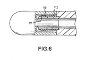
- the compression ring 110 defines a generally flat surface 111 facing inwardly toward the mounting shaft and a generally convex outwardly facing surface 112.
- the pull ring assembly may include more than two pull wires attached to the pull ring around its circumference, with corresponding guide channels provided in the distal tip to guide the individual pull wires first toward the tip element of the distal tip and then to loop back to the handle actuator.
- the compression ring as shown in Figs. 5 and 6 could have shapes other than those specifically depicted.
Landscapes
- Health & Medical Sciences (AREA)
- Engineering & Computer Science (AREA)
- Life Sciences & Earth Sciences (AREA)
- Heart & Thoracic Surgery (AREA)
- Veterinary Medicine (AREA)
- Public Health (AREA)
- General Health & Medical Sciences (AREA)
- Animal Behavior & Ethology (AREA)
- Surgery (AREA)
- Biomedical Technology (AREA)
- Molecular Biology (AREA)
- Mechanical Engineering (AREA)
- Otolaryngology (AREA)
- Nuclear Medicine, Radiotherapy & Molecular Imaging (AREA)
- Plasma & Fusion (AREA)
- Physics & Mathematics (AREA)
- Cardiology (AREA)
- Medical Informatics (AREA)
- Biophysics (AREA)
- Pulmonology (AREA)
- Anesthesiology (AREA)
- Hematology (AREA)
- Media Introduction/Drainage Providing Device (AREA)
- Surgical Instruments (AREA)
Claims (15)
- Medizinische Katheteranordnung (12), mit:einem lenkbaren Katheterschaft (21, 21b), der ein distales Ende und einen hohlen Innenraum (23) definiert;einer distalen Spitze (30, 60, 80) an dem distalen Ende des Katheterschafts (21, 21b) und die ein Spitzenelement (31, 61, 81) und einen sich in den hohlen Innenraum (23) des Katheterschafts (21, 21b) erstreckenden Befestigungsschaft (38, 62, 82) aufweist;einer Zugringanordnung (50, 71, 91) mit einem Zugring (51, 72, 91) und daran angebrachten Zugdrähten (52, 53; 73, 74; 93, 94); undwobei die distale Spitze (30, 60, 80) Führungskanäle (41, 42; 95, 96) bereitstellt, durch die die Zugdrähte (52, 53; 73, 74; 93, 94) jeweils geführt werden, so dass sich diese zunächst von dem Zugring (51, 72, 92) in Richtung des Spitzenelements (31, 61, 81) erstrecken und dann in Richtung und durch den Katheterschaft (21, 21b) umkehren,wobei die medizinische Katheteranordnung (12) dadurch gekennzeichnet ist, dass der Zugring (51, 72, 92) um den Befestigungsschaft (38, 72, 82) angeordnet ist, undein Ziehen der Zugdrähte (52, 53; 72, 74; 93, 94) bewirkt, dass der Zugring (51, 72, 92) kippt und schwankt, wobei sich dadurch der Katheterschaft (21, 21b) biegt und ebenfalls den Zugring (51, 72, 92) in Richtung des Spitzenelements (31, 61, 81) zieht.
- Medizinische Katheteranordnung (12) nach Anspruch 1, wobei der Befestigungsschaft (38, 62, 82) einen sich nach außen erstreckenden ringförmigen Flansch (64) mit sich axial dorthindurch erstreckenden Durchgängen (65, 66) aufweist, die die Führungskanäle (41, 42; 65, 66; 95, 96) aufweisen.
- Medizinische Katheteranordnung (12) nach Anspruch 2, wobei der Befestigungsschaft (38, 62, 82) einen mit dem Spitzenelement (31, 61, 81) verbundenen distalen Abschnitt (63) und einen sich in den Katheterschaft (21, 21b) erstreckenden proximalen Abschnitt (67) aufweist, wobei der sich nach außen erstreckende kreisförmige Flansch (64) einteilig mit dem distalen Abschnitt (63) ist, und wobei der proximale Abschnitt (67) Oberflächenvorsprünge zum Ergreifen des Katheterschafts aufweist, wobei die Oberflächenvorsprünge Widerhaken (68) aufweisen.
- Medizinische Katheteranordnung (12) nach Anspruch 3, wobei axiale Kerben (69, 70) in den Widerhaken (68) vorgesehen sind, die mit den axialen Durchgängen (41, 42; 65, 66; 95, 96) ausgerichtet sind und die die Führungskanäle aufweisen.
- Medizinische Katheteranordnung (12) nach Anspruch 1, mit einem Kompressionsring (100, 110), der einen distalen Endbereich des Katheterschafts (21, 21b) gegen eine äußere Fläche des Befestigungsschafts (38, 62, 82) zusammendrückt.
- Medizinische Katheteranordnung (12) nach Anspruch 5, wobei die äußere Fläche des Befestigungsschafts (38, 62, 82) axiale Kerben (95, 96) darin aufweist, die die Führungskanäle aufweisen.
- Medizinische Katheteranordnung (12) nach Anspruch 6, wobei der Kompressionsring (100, 110) einen im Allgemeinen rechteckigen Querschnitt hat oder wobei der Kompressionsring (100, 110) eine nach innen in Richtung des Befestigungsschafts (38, 62, 82) ausgerichtete im Allgemeinen flache Fläche (111) und eine im Allgemeinen konvexe nach außen gerichtete Fläche (112) aufweist.
- Medizinische Katheteranordnung (12) nach Anspruch 1, wobei das Spitzenelement (31, 61, 81) eine äußere kreisförmige Kante (34) definiert und der Zugring (51, 72, 92) zwischen dem Katheterschaft (21, 21b) und der äußeren kreisförmigen Kante (34) angeordnet ist.
- Medizinische Katheteranordnung (12) nach Anspruch 1, wobei die distale Spitze (30, 60, 80) zwei Führungskanäle (41, 42; 65, 66; 95, 96) an zwei diametral gegenüberliegenden Seiten davon umfasst, wobei bevorzugt die Zugringanordnung (50, 71, 91) zwei Zugdrähte (52, 53; 73, 74; 93, 94) aufweist, die an diametral gegenüberliegenden Positionen an dem Zugring (51, 72, 92) befestigt sind.
- Medizinische Katheteranordnung (12) nach Anspruch 1, wobei die Zugdrähte (52, 53; 73, 74; 93, 94) entlang wenigstens einem Bereich ihrer Länge flach sind.
- Medizinische Katheteranordnung (12) nach Anspruch 1, wobei jeder Zugdraht (52, 53; 73, 74; 93, 94) mit einer inneren Fläche des Zugrings (51, 72, 92) verbunden ist.
- Medizinische Katheteranordnung (12) nach Anspruch 11, wobei jeder Zugdraht (52, 53; 73, 74; 93, 94) mit dem Zugring (51, 72, 92) durch eine Schweißung verbunden ist.
- Medizinische Katheteranordnung (12) nach einem der vorhergehenden Ansprüche, wobei die Anordnung eine Abtragungskatheteranordnung ist;
wobei das Spitzenelement (31, 61, 81) eine Spitzenelektrode ist, und
wobei die Zugdrähte (52, 53; 73, 74; 93, 94) jeweils so geführt sind, dass diese sich zunächst von dem Zugring (51, 72, 92) in Richtung der Spitzenelektrode erstrecken und dann zurück in Richtung und durch den Katheterschaft (21, 21b) umkehren, so dass ein Ziehen der Zugdrähte (52, 53; 73, 74; 93, 94) zum Bewirken, dass der Zugrings den Katheterschaft (21, 21b) biegt, bewirkt, dass der sich Zugring mit der Spitzenelektrode verriegelt. - Abtragungskatheteranordnung (12) nach Anspruch 13, wobei die distale Spitze (30, 60, 80) einen Fluidverteiler (33) zwischen der Spitzenelektrode und des Befestigungsschafts (38, 62, 82) aufweist, und wobei jeder der Führungskanäle (41, 42; 65, 66; 95, 96) einen gebogenen Abschnitt und einen geradlinigen Abschnitt in dem Befestigungschaft (38, 62, 82) aufweist.
- Abtragungskatheteranordnung (12) nach Anspruch 14, wobei der Befestigungsschaft (38, 62, 82) und die Spitzenelektrode einteilig sind.
Applications Claiming Priority (2)
| Application Number | Priority Date | Filing Date | Title |
|---|---|---|---|
| US11/963,441 US8162934B2 (en) | 2007-12-21 | 2007-12-21 | Medical catheter assembly with deflection pull ring and distal tip interlock |
| PCT/US2008/083731 WO2009082570A1 (en) | 2007-12-21 | 2008-11-17 | Medical catheter assembly with deflection pull ring and distal tip interlock |
Publications (4)
| Publication Number | Publication Date |
|---|---|
| EP2190515A1 EP2190515A1 (de) | 2010-06-02 |
| EP2190515A4 EP2190515A4 (de) | 2011-03-16 |
| EP2190515B1 EP2190515B1 (de) | 2013-05-29 |
| EP2190515B9 true EP2190515B9 (de) | 2013-08-28 |
Family
ID=40789513
Family Applications (1)
| Application Number | Title | Priority Date | Filing Date |
|---|---|---|---|
| EP08865610.3A Active EP2190515B9 (de) | 2007-12-21 | 2008-11-17 | Medizinische katheteranordnung mit biegbarem zugring und vorrichtung zur arretierung einer distalen spitze |
Country Status (5)
| Country | Link |
|---|---|
| US (3) | US8162934B2 (de) |
| EP (1) | EP2190515B9 (de) |
| JP (1) | JP5449190B2 (de) |
| CN (1) | CN101932357B (de) |
| WO (1) | WO2009082570A1 (de) |
Families Citing this family (37)
| Publication number | Priority date | Publication date | Assignee | Title |
|---|---|---|---|---|
| US8162934B2 (en) | 2007-12-21 | 2012-04-24 | St. Jude Medical, Atrial Fibrillation Division, Inc. | Medical catheter assembly with deflection pull ring and distal tip interlock |
| US9724192B2 (en) * | 2011-11-08 | 2017-08-08 | Valtech Cardio, Ltd. | Controlled steering functionality for implant-delivery tool |
| EP2604305A1 (de) * | 2011-12-16 | 2013-06-19 | VascoMed GmbH | Katheter und Verfahren zur Herstellung desselben |
| US8702647B2 (en) * | 2012-04-19 | 2014-04-22 | Medtronic Ablation Frontiers Llc | Catheter deflection anchor |
| US10004877B2 (en) | 2012-05-07 | 2018-06-26 | St. Jude Medical, Atrial Fibrillation Division, Inc. | Deflectable catheter shaft section, catheter incorporating same, and method of manufacturing same |
| US9861738B2 (en) * | 2012-05-07 | 2018-01-09 | St. Jude Medical, Cardiology Division, Inc. | Flex tip fluid lumen assembly with termination tube |
| JP2014023721A (ja) * | 2012-07-26 | 2014-02-06 | Japan Lifeline Co Ltd | 電極カテーテル |
| US10398499B2 (en) | 2013-05-24 | 2019-09-03 | Biosense Webster (Israel) Ltd. | Configurable control handle for catheters and other surgical tool |
| EP2996552B1 (de) | 2013-07-01 | 2024-09-04 | Zurich Medical Corporation | Vorrichtung und verfahren für intravaskuläre messungen |
| US10835183B2 (en) | 2013-07-01 | 2020-11-17 | Zurich Medical Corporation | Apparatus and method for intravascular measurements |
| CN105636634B (zh) | 2013-09-30 | 2019-02-01 | 圣犹达医疗用品心脏病学部门有限公司 | 具有主动回直机构的导管 |
| JP6653698B2 (ja) * | 2014-11-04 | 2020-02-26 | コーニンクレッカ フィリップス エヌ ヴェKoninklijke Philips N.V. | 操縦可能医療装置及びその中のプルワイヤリング |
| AU2015350007A1 (en) | 2014-11-19 | 2017-06-29 | Epix Therapeutics, Inc. | Systems and methods for high-resolution mapping of tissue |
| JP6673598B2 (ja) | 2014-11-19 | 2020-03-25 | エピックス セラピューティクス,インコーポレイテッド | ペーシングを伴う組織の高分解能マッピング |
| AU2015349961A1 (en) | 2014-11-19 | 2017-06-29 | Epix Therapeutics, Inc. | Ablation devices, systems and methods of using a high-resolution electrode assembly |
| CR20170245A (es) * | 2014-12-05 | 2017-09-14 | Edwards Lifesciences Corp | Cateter dirigible con cable de tracción |
| CN105982733A (zh) * | 2015-02-27 | 2016-10-05 | 四川锦江电子科技有限公司 | 一种可控多电极消融装置 |
| US9636164B2 (en) | 2015-03-25 | 2017-05-02 | Advanced Cardiac Therapeutics, Inc. | Contact sensing systems and methods |
| US9860392B2 (en) | 2015-06-05 | 2018-01-02 | Silicon Laboratories Inc. | Direct-current to alternating-current power conversion |
| US10154905B2 (en) * | 2015-08-07 | 2018-12-18 | Medtronic Vascular, Inc. | System and method for deflecting a delivery catheter |
| CN115105018A (zh) * | 2016-02-26 | 2022-09-27 | 新宁研究院 | 具有可旋转芯的成像探针 |
| SG11201807618QA (en) | 2016-03-15 | 2018-10-30 | Epix Therapeutics Inc | Improved devices, systems and methods for irrigated ablation |
| WO2018060495A1 (en) | 2016-09-29 | 2018-04-05 | Koninklijke Philips N.V. | Pullwire crown and crown sleeve for catheter assembly |
| US20200016370A1 (en) * | 2016-09-30 | 2020-01-16 | Takemore Co., Ltd. | Catheter |
| US10786651B2 (en) | 2017-03-07 | 2020-09-29 | Talon Medical, LLC | Steerable guide catheter |
| EP3614946B1 (de) | 2017-04-27 | 2024-03-20 | EPiX Therapeutics, Inc. | Bestimmung der art des kontaktes zwischen katheterspitze und gewebe |
| KR102137994B1 (ko) * | 2017-12-15 | 2020-07-28 | 주식회사 오에스와이메드 | 스티어러블 카테터 |
| CN108066003A (zh) * | 2017-12-29 | 2018-05-25 | 浙江归创医疗器械有限公司 | 消融导管 |
| WO2019140039A1 (en) * | 2018-01-11 | 2019-07-18 | The United State Government As Represented By The United State Department Of Veterans Affairs | Sampling catheter with articulating tip |
| US20200155807A1 (en) * | 2018-06-07 | 2020-05-21 | The Board Of Trustees Of The Leland Stanford Junior University | Small diameter catheter for introduction into the trachea and other orifices, as well as into passages that are difficult to intubate or access |
| EP3628208A1 (de) * | 2018-09-28 | 2020-04-01 | Ambu A/S | Gelenkiger spitzenteil für ein endoskop |
| US11918762B2 (en) | 2018-10-03 | 2024-03-05 | St. Jude Medical, Cardiology Division, Inc. | Reduced actuation force electrophysiology catheter handle |
| EP3636133B1 (de) * | 2018-10-12 | 2024-04-03 | Ambu A/S | Gelenkiger spitzenteil für ein endoskop |
| EP4167892A1 (de) | 2020-06-19 | 2023-04-26 | Remedy Robotics, Inc. | Systeme und verfahren zur führung intraluminaler vorrichtungen im gefässsystem |
| DE102021109022A1 (de) * | 2021-04-12 | 2022-10-13 | Karl Storz Se & Co. Kg | Schaft für ein flexibles Endoskop oder für ein flexibles endoskopisches Instrument |
| US11707332B2 (en) | 2021-07-01 | 2023-07-25 | Remedy Robotics, Inc. | Image space control for endovascular tools |
| WO2023278789A1 (en) | 2021-07-01 | 2023-01-05 | Remedy Robotics, Inc. | Vision-based position and orientation determination for endovascular tools |
Family Cites Families (29)
| Publication number | Priority date | Publication date | Assignee | Title |
|---|---|---|---|---|
| JPH0724083Y2 (ja) * | 1988-07-20 | 1995-06-05 | 旭光学工業株式会社 | 内視鏡の湾曲操作ワイヤの取付構造 |
| US5273535A (en) * | 1991-11-08 | 1993-12-28 | Ep Technologies, Inc. | Catheter with electrode tip having asymmetric left and right curve configurations |
| CA2109980A1 (en) * | 1992-12-01 | 1994-06-02 | Mir A. Imran | Steerable catheter with adjustable bend location and/or radius and method |
| US5391147A (en) * | 1992-12-01 | 1995-02-21 | Cardiac Pathways Corporation | Steerable catheter with adjustable bend location and/or radius and method |
| US5389073A (en) * | 1992-12-01 | 1995-02-14 | Cardiac Pathways Corporation | Steerable catheter with adjustable bend location |
| US5462527A (en) * | 1993-06-29 | 1995-10-31 | C.R. Bard, Inc. | Actuator for use with steerable catheter |
| EP1046406B1 (de) * | 1992-12-04 | 2003-10-15 | C.R. Bard, Inc. | Bedienelement zur Verwendung mit einem Katheter mit unabhängiger distaler und proximaler Steuerung |
| US5545200A (en) * | 1993-07-20 | 1996-08-13 | Medtronic Cardiorhythm | Steerable electrophysiology catheter |
| US5431168A (en) * | 1993-08-23 | 1995-07-11 | Cordis-Webster, Inc. | Steerable open-lumen catheter |
| US6099524A (en) * | 1994-01-28 | 2000-08-08 | Cardiac Pacemakers, Inc. | Electrophysiological mapping and ablation catheter and method |
| US5882333A (en) * | 1994-05-13 | 1999-03-16 | Cardima, Inc. | Catheter with deflectable distal section |
| US5666970A (en) * | 1995-05-02 | 1997-09-16 | Heart Rhythm Technologies, Inc. | Locking mechanism for catheters |
| US6113572A (en) * | 1995-05-24 | 2000-09-05 | C. R. Bard, Inc. | Multiple-type catheter connection systems |
| US5807249A (en) | 1996-02-16 | 1998-09-15 | Medtronic, Inc. | Reduced stiffness, bidirectionally deflecting catheter assembly |
| JPH09299320A (ja) * | 1996-05-15 | 1997-11-25 | Fuji Photo Optical Co Ltd | 内視鏡のアングル装置 |
| US6840936B2 (en) * | 1996-10-22 | 2005-01-11 | Epicor Medical, Inc. | Methods and devices for ablation |
| US5968052A (en) * | 1996-11-27 | 1999-10-19 | Scimed Life Systems Inc. | Pull back stent delivery system with pistol grip retraction handle |
| US6183463B1 (en) | 1997-12-01 | 2001-02-06 | Cordis Webster, Inc. | Bidirectional steerable cathether with bidirectional control handle |
| US6198974B1 (en) * | 1998-08-14 | 2001-03-06 | Cordis Webster, Inc. | Bi-directional steerable catheter |
| US6926669B1 (en) * | 2000-10-10 | 2005-08-09 | Medtronic, Inc. | Heart wall ablation/mapping catheter and method |
| US6571131B1 (en) | 2000-11-10 | 2003-05-27 | Biosense Webster, Inc. | Deflectable catheter with modifiable handle |
| US7235070B2 (en) * | 2003-07-02 | 2007-06-26 | St. Jude Medical, Atrial Fibrillation Division, Inc. | Ablation fluid manifold for ablation catheter |
| US7229437B2 (en) * | 2003-09-22 | 2007-06-12 | St. Jude Medical, Atrial Fibrillation Division, Inc. | Medical device having integral traces and formed electrodes |
| US7632265B2 (en) * | 2004-05-28 | 2009-12-15 | St. Jude Medical, Atrial Fibrillation Division, Inc. | Radio frequency ablation servo catheter and method |
| US7974674B2 (en) * | 2004-05-28 | 2011-07-05 | St. Jude Medical, Atrial Fibrillation Division, Inc. | Robotic surgical system and method for surface modeling |
| US7740616B2 (en) * | 2005-03-29 | 2010-06-22 | Angiodynamics, Inc. | Implantable catheter and method of using same |
| US20080234660A2 (en) * | 2006-05-16 | 2008-09-25 | Sarah Cumming | Steerable Catheter Using Flat Pull Wires and Method of Making Same |
| US20070270679A1 (en) * | 2006-05-17 | 2007-11-22 | Duy Nguyen | Deflectable variable radius catheters |
| US8162934B2 (en) | 2007-12-21 | 2012-04-24 | St. Jude Medical, Atrial Fibrillation Division, Inc. | Medical catheter assembly with deflection pull ring and distal tip interlock |
-
2007
- 2007-12-21 US US11/963,441 patent/US8162934B2/en not_active Expired - Fee Related
-
2008
- 2008-11-17 JP JP2010539566A patent/JP5449190B2/ja not_active Expired - Fee Related
- 2008-11-17 EP EP08865610.3A patent/EP2190515B9/de active Active
- 2008-11-17 WO PCT/US2008/083731 patent/WO2009082570A1/en active Application Filing
- 2008-11-17 CN CN2008801219288A patent/CN101932357B/zh active Active
-
2012
- 2012-04-23 US US13/453,525 patent/US8556893B2/en active Active
-
2013
- 2013-10-10 US US14/051,143 patent/US20140100566A1/en not_active Abandoned
Also Published As
| Publication number | Publication date |
|---|---|
| CN101932357B (zh) | 2013-12-25 |
| US20120203170A1 (en) | 2012-08-09 |
| EP2190515A1 (de) | 2010-06-02 |
| US8162934B2 (en) | 2012-04-24 |
| JP5449190B2 (ja) | 2014-03-19 |
| WO2009082570A1 (en) | 2009-07-02 |
| US8556893B2 (en) | 2013-10-15 |
| JP2011507606A (ja) | 2011-03-10 |
| EP2190515A4 (de) | 2011-03-16 |
| US20140100566A1 (en) | 2014-04-10 |
| CN101932357A (zh) | 2010-12-29 |
| EP2190515B1 (de) | 2013-05-29 |
| US20090163917A1 (en) | 2009-06-25 |
Similar Documents
| Publication | Publication Date | Title |
|---|---|---|
| EP2190515B9 (de) | Medizinische katheteranordnung mit biegbarem zugring und vorrichtung zur arretierung einer distalen spitze | |
| US10478597B2 (en) | Medical catheter with deflection pull ring and distal tip attachment apparatus | |
| US6500167B1 (en) | Omni-directional steerable catheter | |
| US6198974B1 (en) | Bi-directional steerable catheter | |
| US5507725A (en) | Steerable catheter | |
| EP0879613B1 (de) | Elektrodenkatheter mit Lenkbarer Spitze | |
| US7077823B2 (en) | Bidirectional steerable catheter with slidable mated puller wires | |
| US9433751B2 (en) | Steerable catheter with distal tip orientation sheaths | |
| EP2544749B1 (de) | Magnetisch geführter katheter | |
| JP5734562B2 (ja) | 偏向可能なシース誘導機器 | |
| US6569114B2 (en) | Steerable catheter with struts | |
| US6551271B2 (en) | Asymmetrical bidirectional steerable catheter | |
| CN109963601B (zh) | 入流插管 | |
| JP6249789B2 (ja) | 経皮的心筋内薬物注入カテーテルおよびカテーテルシステム | |
| JP5697273B2 (ja) | 先端偏向操作可能カテーテル | |
| EP2827934B1 (de) | System und verfahren zur kopplung eines rohres an einen griff einer medizinischen vorrichtung | |
| JP5561784B2 (ja) | 電極カテーテル |
Legal Events
| Date | Code | Title | Description |
|---|---|---|---|
| PUAI | Public reference made under article 153(3) epc to a published international application that has entered the european phase |
Free format text: ORIGINAL CODE: 0009012 |
|
| 17P | Request for examination filed |
Effective date: 20100322 |
|
| AK | Designated contracting states |
Kind code of ref document: A1 Designated state(s): AT BE BG CH CY CZ DE DK EE ES FI FR GB GR HR HU IE IS IT LI LT LU LV MC MT NL NO PL PT RO SE SI SK TR |
|
| AX | Request for extension of the european patent |
Extension state: AL BA MK RS |
|
| A4 | Supplementary search report drawn up and despatched |
Effective date: 20110211 |
|
| DAX | Request for extension of the european patent (deleted) | ||
| 17Q | First examination report despatched |
Effective date: 20111028 |
|
| GRAP | Despatch of communication of intention to grant a patent |
Free format text: ORIGINAL CODE: EPIDOSNIGR1 |
|
| GRAS | Grant fee paid |
Free format text: ORIGINAL CODE: EPIDOSNIGR3 |
|
| GRAA | (expected) grant |
Free format text: ORIGINAL CODE: 0009210 |
|
| AK | Designated contracting states |
Kind code of ref document: B1 Designated state(s): AT BE BG CH CY CZ DE DK EE ES FI FR GB GR HR HU IE IS IT LI LT LU LV MC MT NL NO PL PT RO SE SI SK TR |
|
| REG | Reference to a national code |
Ref country code: GB Ref legal event code: FG4D |
|
| REG | Reference to a national code |
Ref country code: CH Ref legal event code: EP |
|
| REG | Reference to a national code |
Ref country code: AT Ref legal event code: REF Ref document number: 613972 Country of ref document: AT Kind code of ref document: T Effective date: 20130615 |
|
| REG | Reference to a national code |
Ref country code: IE Ref legal event code: FG4D |
|
| REG | Reference to a national code |
Ref country code: DE Ref legal event code: R096 Ref document number: 602008025083 Country of ref document: DE Effective date: 20130725 |
|
| REG | Reference to a national code |
Ref country code: AT Ref legal event code: MK05 Ref document number: 613972 Country of ref document: AT Kind code of ref document: T Effective date: 20130529 |
|
| REG | Reference to a national code |
Ref country code: LT Ref legal event code: MG4D |
|
| PG25 | Lapsed in a contracting state [announced via postgrant information from national office to epo] |
Ref country code: AT Free format text: LAPSE BECAUSE OF FAILURE TO SUBMIT A TRANSLATION OF THE DESCRIPTION OR TO PAY THE FEE WITHIN THE PRESCRIBED TIME-LIMIT Effective date: 20130529 Ref country code: NO Free format text: LAPSE BECAUSE OF FAILURE TO SUBMIT A TRANSLATION OF THE DESCRIPTION OR TO PAY THE FEE WITHIN THE PRESCRIBED TIME-LIMIT Effective date: 20130829 Ref country code: GR Free format text: LAPSE BECAUSE OF FAILURE TO SUBMIT A TRANSLATION OF THE DESCRIPTION OR TO PAY THE FEE WITHIN THE PRESCRIBED TIME-LIMIT Effective date: 20130830 Ref country code: ES Free format text: LAPSE BECAUSE OF FAILURE TO SUBMIT A TRANSLATION OF THE DESCRIPTION OR TO PAY THE FEE WITHIN THE PRESCRIBED TIME-LIMIT Effective date: 20130909 Ref country code: FI Free format text: LAPSE BECAUSE OF FAILURE TO SUBMIT A TRANSLATION OF THE DESCRIPTION OR TO PAY THE FEE WITHIN THE PRESCRIBED TIME-LIMIT Effective date: 20130529 Ref country code: PT Free format text: LAPSE BECAUSE OF FAILURE TO SUBMIT A TRANSLATION OF THE DESCRIPTION OR TO PAY THE FEE WITHIN THE PRESCRIBED TIME-LIMIT Effective date: 20130930 Ref country code: LT Free format text: LAPSE BECAUSE OF FAILURE TO SUBMIT A TRANSLATION OF THE DESCRIPTION OR TO PAY THE FEE WITHIN THE PRESCRIBED TIME-LIMIT Effective date: 20130529 Ref country code: IS Free format text: LAPSE BECAUSE OF FAILURE TO SUBMIT A TRANSLATION OF THE DESCRIPTION OR TO PAY THE FEE WITHIN THE PRESCRIBED TIME-LIMIT Effective date: 20130929 Ref country code: SE Free format text: LAPSE BECAUSE OF FAILURE TO SUBMIT A TRANSLATION OF THE DESCRIPTION OR TO PAY THE FEE WITHIN THE PRESCRIBED TIME-LIMIT Effective date: 20130529 Ref country code: SI Free format text: LAPSE BECAUSE OF FAILURE TO SUBMIT A TRANSLATION OF THE DESCRIPTION OR TO PAY THE FEE WITHIN THE PRESCRIBED TIME-LIMIT Effective date: 20130529 |
|
| REG | Reference to a national code |
Ref country code: NL Ref legal event code: VDEP Effective date: 20130529 |
|
| PG25 | Lapsed in a contracting state [announced via postgrant information from national office to epo] |
Ref country code: BG Free format text: LAPSE BECAUSE OF FAILURE TO SUBMIT A TRANSLATION OF THE DESCRIPTION OR TO PAY THE FEE WITHIN THE PRESCRIBED TIME-LIMIT Effective date: 20130829 Ref country code: HR Free format text: LAPSE BECAUSE OF FAILURE TO SUBMIT A TRANSLATION OF THE DESCRIPTION OR TO PAY THE FEE WITHIN THE PRESCRIBED TIME-LIMIT Effective date: 20130529 Ref country code: PL Free format text: LAPSE BECAUSE OF FAILURE TO SUBMIT A TRANSLATION OF THE DESCRIPTION OR TO PAY THE FEE WITHIN THE PRESCRIBED TIME-LIMIT Effective date: 20130529 |
|
| PG25 | Lapsed in a contracting state [announced via postgrant information from national office to epo] |
Ref country code: LV Free format text: LAPSE BECAUSE OF FAILURE TO SUBMIT A TRANSLATION OF THE DESCRIPTION OR TO PAY THE FEE WITHIN THE PRESCRIBED TIME-LIMIT Effective date: 20130529 |
|
| PG25 | Lapsed in a contracting state [announced via postgrant information from national office to epo] |
Ref country code: EE Free format text: LAPSE BECAUSE OF FAILURE TO SUBMIT A TRANSLATION OF THE DESCRIPTION OR TO PAY THE FEE WITHIN THE PRESCRIBED TIME-LIMIT Effective date: 20130529 Ref country code: DK Free format text: LAPSE BECAUSE OF FAILURE TO SUBMIT A TRANSLATION OF THE DESCRIPTION OR TO PAY THE FEE WITHIN THE PRESCRIBED TIME-LIMIT Effective date: 20130529 Ref country code: SK Free format text: LAPSE BECAUSE OF FAILURE TO SUBMIT A TRANSLATION OF THE DESCRIPTION OR TO PAY THE FEE WITHIN THE PRESCRIBED TIME-LIMIT Effective date: 20130529 Ref country code: BE Free format text: LAPSE BECAUSE OF FAILURE TO SUBMIT A TRANSLATION OF THE DESCRIPTION OR TO PAY THE FEE WITHIN THE PRESCRIBED TIME-LIMIT Effective date: 20130529 Ref country code: CZ Free format text: LAPSE BECAUSE OF FAILURE TO SUBMIT A TRANSLATION OF THE DESCRIPTION OR TO PAY THE FEE WITHIN THE PRESCRIBED TIME-LIMIT Effective date: 20130529 |
|
| PG25 | Lapsed in a contracting state [announced via postgrant information from national office to epo] |
Ref country code: RO Free format text: LAPSE BECAUSE OF FAILURE TO SUBMIT A TRANSLATION OF THE DESCRIPTION OR TO PAY THE FEE WITHIN THE PRESCRIBED TIME-LIMIT Effective date: 20130529 Ref country code: NL Free format text: LAPSE BECAUSE OF FAILURE TO SUBMIT A TRANSLATION OF THE DESCRIPTION OR TO PAY THE FEE WITHIN THE PRESCRIBED TIME-LIMIT Effective date: 20130529 |
|
| PLBE | No opposition filed within time limit |
Free format text: ORIGINAL CODE: 0009261 |
|
| STAA | Information on the status of an ep patent application or granted ep patent |
Free format text: STATUS: NO OPPOSITION FILED WITHIN TIME LIMIT |
|
| 26N | No opposition filed |
Effective date: 20140303 |
|
| REG | Reference to a national code |
Ref country code: DE Ref legal event code: R097 Ref document number: 602008025083 Country of ref document: DE Effective date: 20140303 |
|
| REG | Reference to a national code |
Ref country code: CH Ref legal event code: PL |
|
| PG25 | Lapsed in a contracting state [announced via postgrant information from national office to epo] |
Ref country code: CH Free format text: LAPSE BECAUSE OF NON-PAYMENT OF DUE FEES Effective date: 20131130 Ref country code: LI Free format text: LAPSE BECAUSE OF NON-PAYMENT OF DUE FEES Effective date: 20131130 Ref country code: MC Free format text: LAPSE BECAUSE OF FAILURE TO SUBMIT A TRANSLATION OF THE DESCRIPTION OR TO PAY THE FEE WITHIN THE PRESCRIBED TIME-LIMIT Effective date: 20130529 |
|
| REG | Reference to a national code |
Ref country code: IE Ref legal event code: MM4A |
|
| PG25 | Lapsed in a contracting state [announced via postgrant information from national office to epo] |
Ref country code: IE Free format text: LAPSE BECAUSE OF NON-PAYMENT OF DUE FEES Effective date: 20131117 |
|
| PG25 | Lapsed in a contracting state [announced via postgrant information from national office to epo] |
Ref country code: CY Free format text: LAPSE BECAUSE OF FAILURE TO SUBMIT A TRANSLATION OF THE DESCRIPTION OR TO PAY THE FEE WITHIN THE PRESCRIBED TIME-LIMIT Effective date: 20130529 Ref country code: TR Free format text: LAPSE BECAUSE OF FAILURE TO SUBMIT A TRANSLATION OF THE DESCRIPTION OR TO PAY THE FEE WITHIN THE PRESCRIBED TIME-LIMIT Effective date: 20130529 |
|
| PG25 | Lapsed in a contracting state [announced via postgrant information from national office to epo] |
Ref country code: HU Free format text: LAPSE BECAUSE OF FAILURE TO SUBMIT A TRANSLATION OF THE DESCRIPTION OR TO PAY THE FEE WITHIN THE PRESCRIBED TIME-LIMIT; INVALID AB INITIO Effective date: 20081117 Ref country code: LU Free format text: LAPSE BECAUSE OF NON-PAYMENT OF DUE FEES Effective date: 20131117 |
|
| PG25 | Lapsed in a contracting state [announced via postgrant information from national office to epo] |
Ref country code: MT Free format text: LAPSE BECAUSE OF FAILURE TO SUBMIT A TRANSLATION OF THE DESCRIPTION OR TO PAY THE FEE WITHIN THE PRESCRIBED TIME-LIMIT Effective date: 20130529 |
|
| REG | Reference to a national code |
Ref country code: FR Ref legal event code: PLFP Year of fee payment: 8 |
|
| REG | Reference to a national code |
Ref country code: FR Ref legal event code: PLFP Year of fee payment: 9 |
|
| REG | Reference to a national code |
Ref country code: FR Ref legal event code: PLFP Year of fee payment: 10 |
|
| REG | Reference to a national code |
Ref country code: FR Ref legal event code: PLFP Year of fee payment: 11 |
|
| PGFP | Annual fee paid to national office [announced via postgrant information from national office to epo] |
Ref country code: FR Payment date: 20221020 Year of fee payment: 15 |
|
| PGFP | Annual fee paid to national office [announced via postgrant information from national office to epo] |
Ref country code: IT Payment date: 20221111 Year of fee payment: 15 Ref country code: GB Payment date: 20221012 Year of fee payment: 15 Ref country code: DE Payment date: 20221012 Year of fee payment: 15 |
|
| REG | Reference to a national code |
Ref country code: DE Ref legal event code: R082 Ref document number: 602008025083 Country of ref document: DE Representative=s name: ALPSPITZ IP ALLGAYER UND PARTNER PATENTANWAELT, DE |
|
| REG | Reference to a national code |
Ref country code: DE Ref legal event code: R119 Ref document number: 602008025083 Country of ref document: DE |
|
| GBPC | Gb: european patent ceased through non-payment of renewal fee |
Effective date: 20231117 |