EP2544749B1 - Magnetisch geführter katheter - Google Patents
Magnetisch geführter katheter Download PDFInfo
- Publication number
- EP2544749B1 EP2544749B1 EP11754076.5A EP11754076A EP2544749B1 EP 2544749 B1 EP2544749 B1 EP 2544749B1 EP 11754076 A EP11754076 A EP 11754076A EP 2544749 B1 EP2544749 B1 EP 2544749B1
- Authority
- EP
- European Patent Office
- Prior art keywords
- magnet
- catheter
- tubing
- coupler
- tip
- Prior art date
- Legal status (The legal status is an assumption and is not a legal conclusion. Google has not performed a legal analysis and makes no representation as to the accuracy of the status listed.)
- Active
Links
- 230000009975 flexible effect Effects 0.000 claims description 57
- 239000000463 material Substances 0.000 claims description 38
- 230000002262 irrigation Effects 0.000 claims description 15
- 238000003973 irrigation Methods 0.000 claims description 15
- 239000012530 fluid Substances 0.000 claims description 13
- 239000000853 adhesive Substances 0.000 claims description 7
- 230000001070 adhesive effect Effects 0.000 claims description 7
- 238000004891 communication Methods 0.000 claims description 2
- 238000003825 pressing Methods 0.000 claims description 2
- 230000008878 coupling Effects 0.000 claims 1
- 238000010168 coupling process Methods 0.000 claims 1
- 238000005859 coupling reaction Methods 0.000 claims 1
- 238000000034 method Methods 0.000 description 30
- 238000002679 ablation Methods 0.000 description 11
- 230000004323 axial length Effects 0.000 description 9
- 238000004519 manufacturing process Methods 0.000 description 9
- 238000013507 mapping Methods 0.000 description 9
- BASFCYQUMIYNBI-UHFFFAOYSA-N platinum Chemical compound [Pt] BASFCYQUMIYNBI-UHFFFAOYSA-N 0.000 description 8
- 210000001519 tissue Anatomy 0.000 description 8
- 238000010276 construction Methods 0.000 description 7
- 230000008569 process Effects 0.000 description 7
- 230000004044 response Effects 0.000 description 6
- 239000004642 Polyimide Substances 0.000 description 5
- FAPWRFPIFSIZLT-UHFFFAOYSA-M Sodium chloride Chemical compound [Na+].[Cl-] FAPWRFPIFSIZLT-UHFFFAOYSA-M 0.000 description 5
- QJVKUMXDEUEQLH-UHFFFAOYSA-N [B].[Fe].[Nd] Chemical compound [B].[Fe].[Nd] QJVKUMXDEUEQLH-UHFFFAOYSA-N 0.000 description 5
- WABPQHHGFIMREM-UHFFFAOYSA-N lead(0) Chemical compound [Pb] WABPQHHGFIMREM-UHFFFAOYSA-N 0.000 description 5
- 229910001172 neodymium magnet Inorganic materials 0.000 description 5
- 229920001721 polyimide Polymers 0.000 description 5
- 229920006300 shrink film Polymers 0.000 description 5
- 239000011780 sodium chloride Substances 0.000 description 5
- 230000007423 decrease Effects 0.000 description 4
- 239000003989 dielectric material Substances 0.000 description 4
- 229910052697 platinum Inorganic materials 0.000 description 4
- 230000000295 complement effect Effects 0.000 description 3
- 230000004927 fusion Effects 0.000 description 3
- 229910052741 iridium Inorganic materials 0.000 description 3
- GKOZUEZYRPOHIO-UHFFFAOYSA-N iridium atom Chemical compound [Ir] GKOZUEZYRPOHIO-UHFFFAOYSA-N 0.000 description 3
- 230000033001 locomotion Effects 0.000 description 3
- 239000000314 lubricant Substances 0.000 description 3
- 239000000696 magnetic material Substances 0.000 description 3
- 229920000642 polymer Polymers 0.000 description 3
- LFQSCWFLJHTTHZ-UHFFFAOYSA-N Ethanol Chemical compound CCO LFQSCWFLJHTTHZ-UHFFFAOYSA-N 0.000 description 2
- 229920000106 Liquid crystal polymer Polymers 0.000 description 2
- 239000004977 Liquid-crystal polymers (LCPs) Substances 0.000 description 2
- 239000004696 Poly ether ether ketone Substances 0.000 description 2
- 229920002614 Polyether block amide Polymers 0.000 description 2
- 230000002159 abnormal effect Effects 0.000 description 2
- 210000005242 cardiac chamber Anatomy 0.000 description 2
- 230000000747 cardiac effect Effects 0.000 description 2
- 230000008859 change Effects 0.000 description 2
- 238000013461 design Methods 0.000 description 2
- 229920001971 elastomer Polymers 0.000 description 2
- 210000005003 heart tissue Anatomy 0.000 description 2
- 238000009413 insulation Methods 0.000 description 2
- 230000037361 pathway Effects 0.000 description 2
- 239000004033 plastic Substances 0.000 description 2
- 229920003023 plastic Polymers 0.000 description 2
- 238000012545 processing Methods 0.000 description 2
- 239000007779 soft material Substances 0.000 description 2
- 230000007704 transition Effects 0.000 description 2
- QTRRHZGTKNAJSM-UHFFFAOYSA-N C[IH][IH][IH]C[N+]([O-])=O Chemical compound C[IH][IH][IH]C[N+]([O-])=O QTRRHZGTKNAJSM-UHFFFAOYSA-N 0.000 description 1
- RYGMFSIKBFXOCR-UHFFFAOYSA-N Copper Chemical compound [Cu] RYGMFSIKBFXOCR-UHFFFAOYSA-N 0.000 description 1
- 239000004677 Nylon Substances 0.000 description 1
- 238000013459 approach Methods 0.000 description 1
- 230000006793 arrhythmia Effects 0.000 description 1
- 206010003119 arrhythmia Diseases 0.000 description 1
- 230000000712 assembly Effects 0.000 description 1
- 238000000429 assembly Methods 0.000 description 1
- 230000001746 atrial effect Effects 0.000 description 1
- 238000013153 catheter ablation Methods 0.000 description 1
- 239000011248 coating agent Substances 0.000 description 1
- 238000000576 coating method Methods 0.000 description 1
- 230000006835 compression Effects 0.000 description 1
- 238000007906 compression Methods 0.000 description 1
- 229910052802 copper Inorganic materials 0.000 description 1
- 239000010949 copper Substances 0.000 description 1
- 230000007797 corrosion Effects 0.000 description 1
- 238000005260 corrosion Methods 0.000 description 1
- 230000001186 cumulative effect Effects 0.000 description 1
- 230000000694 effects Effects 0.000 description 1
- 238000001125 extrusion Methods 0.000 description 1
- 239000000835 fiber Substances 0.000 description 1
- 238000003780 insertion Methods 0.000 description 1
- 230000037431 insertion Effects 0.000 description 1
- 230000003902 lesion Effects 0.000 description 1
- 230000013011 mating Effects 0.000 description 1
- 230000004048 modification Effects 0.000 description 1
- 238000012986 modification Methods 0.000 description 1
- 230000002107 myocardial effect Effects 0.000 description 1
- 230000009972 noncorrosive effect Effects 0.000 description 1
- 229920001778 nylon Polymers 0.000 description 1
- 230000001717 pathogenic effect Effects 0.000 description 1
- 239000011347 resin Substances 0.000 description 1
- 229920005989 resin Polymers 0.000 description 1
- 230000033764 rhythmic process Effects 0.000 description 1
- 229910052710 silicon Inorganic materials 0.000 description 1
- 239000010703 silicon Substances 0.000 description 1
- 238000004513 sizing Methods 0.000 description 1
- 229910001220 stainless steel Inorganic materials 0.000 description 1
- 239000010935 stainless steel Substances 0.000 description 1
- 239000000126 substance Substances 0.000 description 1
- 230000033912 thigmotaxis Effects 0.000 description 1
Images


Classifications
-
- A—HUMAN NECESSITIES
- A61—MEDICAL OR VETERINARY SCIENCE; HYGIENE
- A61M—DEVICES FOR INTRODUCING MEDIA INTO, OR ONTO, THE BODY; DEVICES FOR TRANSDUCING BODY MEDIA OR FOR TAKING MEDIA FROM THE BODY; DEVICES FOR PRODUCING OR ENDING SLEEP OR STUPOR
- A61M25/00—Catheters; Hollow probes
- A61M25/01—Introducing, guiding, advancing, emplacing or holding catheters
- A61M25/0105—Steering means as part of the catheter or advancing means; Markers for positioning
- A61M25/0127—Magnetic means; Magnetic markers
-
- A—HUMAN NECESSITIES
- A61—MEDICAL OR VETERINARY SCIENCE; HYGIENE
- A61B—DIAGNOSIS; SURGERY; IDENTIFICATION
- A61B5/00—Measuring for diagnostic purposes; Identification of persons
- A61B5/06—Devices, other than using radiation, for detecting or locating foreign bodies ; determining position of probes within or on the body of the patient
- A61B5/061—Determining position of a probe within the body employing means separate from the probe, e.g. sensing internal probe position employing impedance electrodes on the surface of the body
- A61B5/062—Determining position of a probe within the body employing means separate from the probe, e.g. sensing internal probe position employing impedance electrodes on the surface of the body using magnetic field
-
- A—HUMAN NECESSITIES
- A61—MEDICAL OR VETERINARY SCIENCE; HYGIENE
- A61B—DIAGNOSIS; SURGERY; IDENTIFICATION
- A61B18/00—Surgical instruments, devices or methods for transferring non-mechanical forms of energy to or from the body
- A61B18/04—Surgical instruments, devices or methods for transferring non-mechanical forms of energy to or from the body by heating
- A61B18/12—Surgical instruments, devices or methods for transferring non-mechanical forms of energy to or from the body by heating by passing a current through the tissue to be heated, e.g. high-frequency current
- A61B18/14—Probes or electrodes therefor
- A61B18/1492—Probes or electrodes therefor having a flexible, catheter-like structure, e.g. for heart ablation
-
- A—HUMAN NECESSITIES
- A61—MEDICAL OR VETERINARY SCIENCE; HYGIENE
- A61B—DIAGNOSIS; SURGERY; IDENTIFICATION
- A61B18/00—Surgical instruments, devices or methods for transferring non-mechanical forms of energy to or from the body
- A61B2018/00571—Surgical instruments, devices or methods for transferring non-mechanical forms of energy to or from the body for achieving a particular surgical effect
- A61B2018/00577—Ablation
-
- A—HUMAN NECESSITIES
- A61—MEDICAL OR VETERINARY SCIENCE; HYGIENE
- A61B—DIAGNOSIS; SURGERY; IDENTIFICATION
- A61B18/00—Surgical instruments, devices or methods for transferring non-mechanical forms of energy to or from the body
- A61B2018/00636—Sensing and controlling the application of energy
- A61B2018/00773—Sensed parameters
- A61B2018/00791—Temperature
- A61B2018/00821—Temperature measured by a thermocouple
-
- A—HUMAN NECESSITIES
- A61—MEDICAL OR VETERINARY SCIENCE; HYGIENE
- A61B—DIAGNOSIS; SURGERY; IDENTIFICATION
- A61B2218/00—Details of surgical instruments, devices or methods for transferring non-mechanical forms of energy to or from the body
- A61B2218/001—Details of surgical instruments, devices or methods for transferring non-mechanical forms of energy to or from the body having means for irrigation and/or aspiration of substances to and/or from the surgical site
- A61B2218/002—Irrigation
-
- A—HUMAN NECESSITIES
- A61—MEDICAL OR VETERINARY SCIENCE; HYGIENE
- A61M—DEVICES FOR INTRODUCING MEDIA INTO, OR ONTO, THE BODY; DEVICES FOR TRANSDUCING BODY MEDIA OR FOR TAKING MEDIA FROM THE BODY; DEVICES FOR PRODUCING OR ENDING SLEEP OR STUPOR
- A61M25/00—Catheters; Hollow probes
- A61M25/01—Introducing, guiding, advancing, emplacing or holding catheters
- A61M25/0105—Steering means as part of the catheter or advancing means; Markers for positioning
- A61M2025/0166—Sensors, electrodes or the like for guiding the catheter to a target zone, e.g. image guided or magnetically guided
-
- A—HUMAN NECESSITIES
- A61—MEDICAL OR VETERINARY SCIENCE; HYGIENE
- A61M—DEVICES FOR INTRODUCING MEDIA INTO, OR ONTO, THE BODY; DEVICES FOR TRANSDUCING BODY MEDIA OR FOR TAKING MEDIA FROM THE BODY; DEVICES FOR PRODUCING OR ENDING SLEEP OR STUPOR
- A61M25/00—Catheters; Hollow probes
- A61M25/0009—Making of catheters or other medical or surgical tubes
- A61M25/0012—Making of catheters or other medical or surgical tubes with embedded structures, e.g. coils, braids, meshes, strands or radiopaque coils
-
- A—HUMAN NECESSITIES
- A61—MEDICAL OR VETERINARY SCIENCE; HYGIENE
- A61M—DEVICES FOR INTRODUCING MEDIA INTO, OR ONTO, THE BODY; DEVICES FOR TRANSDUCING BODY MEDIA OR FOR TAKING MEDIA FROM THE BODY; DEVICES FOR PRODUCING OR ENDING SLEEP OR STUPOR
- A61M25/00—Catheters; Hollow probes
- A61M25/0043—Catheters; Hollow probes characterised by structural features
- A61M25/005—Catheters; Hollow probes characterised by structural features with embedded materials for reinforcement, e.g. wires, coils, braids
Definitions
- This invention relates generally to medical instruments, and, more specifically, to a navigable catheter device positionable within a body of a patient using an externally applied magnetic field.
- US 2009/012517 A1 discloses a magnetically guided catheter.
- Catheters are flexible, tubular devices that are widely used by physicians performing medical procedures to gain access into interior regions of the body. Careful and precise positioning of the catheters within the body is important to successfully completing such medical procedures. This is particularly so when catheters are used to produce emissions of energy within the body during tissue ablation procedures. Conventionally, positioning of such catheters was accomplished with mechanically steerable devices. More recently, magnetically navigable catheter devices have been developed that are navigated with an externally applied magnetic field. Such catheter devices can be complex in their construction, and therefore are difficult to manufacture and relatively expensive to produce.
- Magnetic stereotactic systems have been developed that are particularly advantageous for positioning of catheters, as well as other devices, into areas of the body that were previously inaccessible.
- the magnetic fields and gradients are generated to precisely control the position of the catheter within the patient's body.
- physicians may operate the catheter, for example, to ablate tissue to interrupt potentially pathogenic heart rhythms or to clear a passage in the body, for example.
- stereotactic systems monitor the position of a tip of the catheter in response to the applied magnetic fields using well established feedback and control algorithms the catheter tip may be guided to and positioned in a desired location within the patient's body.
- the magnetic response of the catheter can be a limitation on the precise control of a catheter when used with such magnetic guidance systems. Improvements in catheters utilized with magnetic guidance and control systems, such as stereotactic systems, are desired. Specifically, a low cost, yet high performance magnetically guided catheter is desirable.
- a catheter according to claim 1 can be provided.
- a catheter in one aspect, includes a flexible tubing having a proximal end and a distal end.
- An electrode assembly is attached to the distal end of the flexible tubing.
- the electrode assembly includes an electrically conductive tip electrode and a coupler which is connected between the tip electrode and the distal end of the flexible tubing.
- the coupler and the tip electrode are coupled by an interlocking connection.
- a first magnet is at least partially housed in the coupler.
- a fluid lumen extends through the flexible tubing to the coupler. The fluid lumen extends completely through the first magnet and connects to at least one port formed in the electrode assembly.
- a second magnet is spaced from the electrode assembly along a longitudinal axis of the tubing. The first magnet and the second magnet are responsive to an external magnetic field to selectively position and guide the electrode assembly within a body of a patient.
- a catheter in another aspect, includes an electrode assembly attached to the distal end of the flexible tubing and including a first magnet at least partially therein.
- the electrode assembly includes an electrically conductive tip electrode and an internal coupler which is connected between the tip electrode and the distal end of the flexible tubing.
- a second magnet is spaced from the electrode assembly along a longitudinal axis of the tubing.
- the flexible tubing is a unitary tubing, and the second magnet is pushed inside the flexible tubing after the unitary flexible tubing is formed.
- the first magnet and the second magnet are responsive to an external magnetic field to selectively position and guide the electrode assembly within a body of a patient.
- a catheter in yet another aspect, includes an electrode assembly attached to the distal end of the flexible tubing and includes a first magnet at least partially therein.
- the electrode assembly includes an electrically conductive tip electrode and an internal coupler which is connected between the tip electrode and the distal end of the flexible tubing
- a second magnet is spaced from the electrode assembly along a longitudinal axis of the tubing.
- the flexible tubing is a unitary tubing, and the second magnet is pushed inside the flexible tubing after the unitary flexible tubing is formed.
- the first magnet and the second magnet are responsive to an external magnetic field to selectively position and guide the electrode assembly within a body of a patient.
- Figure 1 illustrates a first exemplary non-steerable, single-use magnetically guided catheter 100 (not showing all features of the claims) generally including a flexible outer tube, or tubing, 102, a tip assembly 104, positioning magnets 106 and 108 separately provided from and spaced from tip assembly 104, a Y connector 110, a luer device 112, and an electrical connector 114.
- Luer device 112 is used to open or close a flow path so that fluid is passed through Y-connector 110 and tubing 102 to tip assembly 104 for irrigation purposes.
- Electrical connector 114 establishes electrical connection with a power source (not shown) that operates electrodes of tip assembly 104 to perform, for example, ablation procedures, mapping or pacing procedures, or to perform other aspects of a medical procedure.
- catheter 100 is believed to be particularly advantageous as an ablation catheter for creating endocardial lesions during cardiac ablation procedures to treat arrhythmias, and also for cardiac electrophysiological mapping and delivering diagnostic pacing stimuli.
- ablation catheter for creating endocardial lesions during cardiac ablation procedures to treat arrhythmias
- cardiac electrophysiological mapping and delivering diagnostic pacing stimuli are also provided.
- the invention and the appended claims are not intended to be limited to any specific example, including but not limited to specific examples or embodiments described herein, except when explicitly defined as such in the appended claims.
- Y-connector 110 separates an inner tube 116 from electrical lead wires (not shown) extending between tip assembly 104 and electrical connector 114. More specifically, tube 116 and the lead wires forward of Y-connector 110 pass internally through outer tube 102, while aft of Y-connector 110, inner tube 116 and leads for the lead wires are exposed and separated for connection to a fluid source (not shown) and the power source, respectively.
- electrical connector 114 is a known connector configured to engage the power source or a power supply with, for example, a plug-in connection.
- One suitable electrical connector is a 14 pin REDEL ® plastic connector commercially available from LEMO of Rohnert Park, California, although other connectors from various manufacturers may likewise be utilized.
- Outer tube 102 includes a proximal end 118 coupled to Y-connector 110, a distal end 120 coupled to tip assembly 104, and an axial length extending between proximal end 118 and distal end 120.
- flexible tubing 102 is fabricated according to known processes, such as multilayer processing including extrusion processes, mandrel-based processes and combinations thereof from any suitable tubing material known in the art of medical instruments, such as engineered nylon resins and plastics, including but not limited to PEBAX ® tubing of Ato Fina Chemicals, France.
- tubing 102 is fabricated from a first tubing material defining a first portion 122 of tubing 102 between Y connector 110 and magnet 108, a second tubing material defining a second portion 124 of tubing 102 between magnet 106 and magnet 108, and a third tubing material defining a third portion 126 of tubing 102 extending between magnet 106 and tip assembly 104.
- first portion 122, second portion 124 and/or third portion 126 are fabricated from different materials and grades of materials for enhanced performance of tubing 102 in use of catheter assembly 100.
- Tubing 102 by virtue of portions 122, 124, and 126 having varying flexible properties, is sometimes referred to as a multi-flexible tube.
- the first material defining first portion 122 of tubing 102 is a comparatively rigid and kink resistant braided material.
- First portion 122 is formed with different portions of braided material, semi-soft material, and soft material fused to one another so that first portion 122 becomes increasingly flexible along the axial length as first portion 122 approaches magnet 108.
- the second material defining second portion 124 of tubing 102, and the third material defining third portion 126 of tubing 102 is a soft and flexible material having approximately equal flexible properties.
- each of tubing portions 122, 124, and 126 between tip assembly 104 and magnets 106 and 108 share a common outside diameter of, for example, 2,3 mm (7 French), although in other embodiments, tubing portions 122, 124 and 126 have varied diameters.
- first portion 122 extends for a majority of the axial length of tubing 102 between proximal end portion 118 and distal end portion 120.
- Second portion 124 of tubing 102 extends for a shorter length than the length of first portion 122
- third portion 126 of tubing 102 extends for a length that is shorter than the length of second portion 124.
- first portion 122 extends for an axial length of about 126.3 cm
- second portion 124 extends for an axial length of about 2.2 cm
- third portion 126 extends for an axial length of about 0.8 cm, although other relative lengths of the tube portions may likewise be employed in other embodiments.
- tube portions 122, 124 and 126 allow tip assembly 104 to be more precisely positioned within a patient's body, while also avoiding problems of kinks and excessive deflection of tubing 102 along the majority of its length during use and handling.
- magnet 106 is spaced a first distance from tip assembly 104, and magnet 108 is spaced a second, greater distance from magnet 106 since tubing portion 124 is longer than tubing portion 126.
- tip assembly 104 which as explained below also includes a positioning magnet (not shown in Figure 1 )
- the spacing of magnets 106 and 108 permits positioning adjustment of tip assembly 104 in response to variations in an externally applied magnetic field that may otherwise not be possible, if magnets 106 and 108 were provided in an equal or uniform spaced relation to one another. It is contemplated, however, that in another embodiment tip assembly 104, magnet 106 and magnet 108 are equally spaced from one another.
- a distal end portion 128 of catheter 100 including tip assembly 104 is navigated to a site in the body where a medical procedure, such as an atrial mapping, pacing and/or ablation are to occur.
- Distal end portion 128 may extend, for example, into a heart chamber of a patient.
- a magnetic field is applied to provide an orienting force to distal end portion 128, causing the tip positioning magnet and magnets 106 and 108 to respond to the applied magnetic field and flex tubing portions 124 and 122 to precisely position tip assembly 104 for performance of the procedure at a specific location.
- the magnetic fields used to orient tip assembly 104 are, in one embodiment, generated with a magnetic stereotactic system (not shown).
- Such stereotactic systems are known and are commercially available from, for example, Stereotaxis of St. Louis, Missouri.
- Such systems may include movable source magnets outside the body of the patient, and operative details of such systems are disclosed in, for example, U.S. Patent Nos. 6,475,223 and 6,755,816 .
- catheter 100 is advantageous for use with a stereotactic system, it is contemplated that magnetic fields and gradients to deflect catheter tip assembly 104 may alternatively be generated by other systems and techniques if desired.
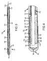
- FIG. 2 is a magnified view of distal end portion 128 of catheter 100 shown in Figure 1 .
- Tip assembly 104 is coupled to a first end 130 of tube portion 126 and magnet 106 is coupled to a second end 132 of tube portion 126.
- a first end 134 of tube portion 124 is coupled to magnet 106 and a second end 136 of tube portion 124 is coupled to magnet 108.
- a first end 138 of tube portion 122 is coupled to magnet 108, and a second end (not shown in Figure 2 ) of tube portion 122 is coupled to connector 110 (shown in Figure 1 ).
- tip assembly 104 includes irrigation ports or openings 140 for passage of fluid from within tubing 102 (shown in Figure 1 ) to an exterior of tip assembly 104 when located in the body of a patient.
- Figure 3 is a cross sectional view of distal end portion 128 wherein inner tube 116 defines a central lumen 142 extending through each tube portion 122, 124, and 126, and also through central bores formed in magnets 106 and 108.
- Inner tube 116 has an outer diameter that is smaller than an inner diameter of tubing 102 and its portions 122, 124, and 126 such that space extends between an outer surface of inner tube 116 and an inner surface of tubing 102. in one embodiment, this space is used to accommodate lead wires for electrical components of tip assembly 104.
- Tip assembly 104 also includes a positioning magnet 144 having an internal bore 146 passing therethrough.
- Inner tube 116 passes through central bore 146 in magnet 144.
- Central lumen 142 is in fluid communication with luer 112 (shown in Figure 1 ) on one end and with irrigation ports 140 extending through tip assembly 104 at the other end.
- an irrigation fluid such as saline
- Inner tube 116 may be, for example, a braided polyimide tube that maintains the flowpath through lumen 142 in all orientations of tip assembly 104, without compromising the flexibility of tubing 102.
- FIG 4 is a magnified cross sectional view of tip assembly 104.
- tip assembly 104 includes a tip electrode 150, a coupler 152, a band electrode 154, positioning magnet 144, and a temperature sensor 156.
- Lead wires 158, 160 extend to tip electrode 150, and to band electrode 154 on first respective ends 162, 164 thereof, and to connector 114 (shown in Figure 1 ) on second ends (not shown) so that electrodes 150 and 154 may be energized by a power source (not shown).
- tip electrode 150 may be, for example an 2,7 mm (8 Fr) hemispherical-shaped tip electrode that is 2 mm in length. In other embodiments, other sizes of tip electrodes may be utilized, including but not limited to 4 mm or 8 mm tip electrodes.
- Tip electrode 150 is formed with a plurality of openings that form irrigation ports 140 for saline irrigation. In the exemplary embodiment, tip electrode 150 is fabricated from 90% platinum and 10% iridium, or other materials known in the art such that tip electrode 150 is viewable under fluoroscopic exposure. While formed as an integral unit, tip electrode 150 may include multiple electrode elements, such as ring electrodes for electrophysiological mapping purposes, spaced from one another by dielectric materials as is known in the art.
- Coupler 152 is a generally cylindrical, electrically nonconductive member. It is typically made of a polymer such as PEEK TM , which is relatively rigid compared to rubber and has a limited amount of flexibility and resiliency to form a snap-fit connection, for example.
- Tip electrode 150 is formed with an annular projection 166 on its outer surface that engages a groove 168 within a first end 170 of coupler 152 to form a snap-fit, interlocking connection.
- any mating configuration of tip assembly 104 and coupler 152 may be used.
- Coupler 152 includes a second end 172 that is fitted within first end 130 of tube portion 126. Additionally, or alternatively thereto, first end 170 of coupler 152 is adhered to tip electrode 150.
- Second end 172 of coupler 152 is adhered to the inner diameter of tube portion 126. Heat shrink techniques or adhesives may also be utilized to permanently attach coupler 152 to tube portion 126 and/or tip electrode 150.
- Positioning magnet 144 is disposed in a cavity which is formed at least partially inside the coupler 152 and which may be formed partially inside coupler 152 and partially inside tip electrode 150.
- Coupler 152 houses positioning magnet 144 in tip assembly 104 and supports optional band electrode 154, is more rigid than flexible tubing 102, and provides a convenient and reliable connection between tip electrode 150 and third portion 126 of flexible tubing 102.
- Band electrode 154 is, in one embodiment, an 2,7 mm (8 Fr) ring-shaped band electrode that is for example, 2 mm in length, and spaced from tip electrode 150 by a predetermined distance of 2 mm.
- Band electrode 154 is, in one embodiment, fabricated from the same material as or a different material from tip electrode 150 and is attached to an outer surface of coupler 152.
- tip positioning magnet 144 is a generally cylindrical shaped permanent magnet fabricated from a known magnetic material, such as neodymium-iron boron - 45 (NdFeB-45).
- magnet 144 is formed from other materials and may have shapes different from the elongated cylindrical shape illustrated.
- magnet 144 includes an axially extending recess, or groove, 176 formed into an exterior of magnet 144.
- Lead wires 158, 160, and a lead wire 178 for temperature sensor 158 pass through recess 176 in a space defined by recess 176 and an inner surface of coupler 152.
- Temperature sensor 158 is, in one embodiment, a thermocouple type temperature sensor, and lead wires 158, 160, arid 178 are, for example, 38 AWG wires having quad polyimide insulation.
- Tip assembly 104 is particularly suited for ablation procedures wherein electrodes 150 and 154 are energized to deliver radio frequency waves at the site of an abnormal electrical pathway in the body. Radiofrequency (RF) energy may therefore be applied to biological tissue in proximity to tip assembly 104. Ablation procedures are typically used, for example, within the interior chambers of the heart to thermally ablate cardiac tissue. Electrodes 150 and 154 may additionally be operated to record intracardiac signals and to provide pacing signals.
- RF Radiofrequency
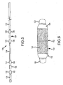
- FIG 5 is an exploded view of catheter distal end portion 128 (shown in Figure 1 ).
- Magnets 106 and 108 are each permanent magnets formed from, for example, neodymium-iron boron - 45 (NdFeB-45) into an elongated tubular shape.
- second end 132 of tube portion 126, first and second ends 134, 136 of tube portion 124, and first end 138 of tube portion 122 are formed into outwardly flared sockets 182, 184, 186 and 188.
- Magnet 106 is received in socket 182 of tube second end 132 and socket 184 of tube portion first end 134.
- Magnet 108 is received in socket 186 of tube portion second end 136 and socket 188 of tube portion first end 138.
- sockets 182, 184, 186, and 188 are formed with a flaring tool and extend, for example, an axial length of about 2.5 mm.
- Sockets 182, 184, 186, and 188 are, in the exemplary embodiment, adhered to magnets 106 and 108, respectively, and heat shrunk to fuse sockets 182 and 184 to magnet 106 and sockets 186 and 188 to magnet 108.
- sockets 182, 184, 186, and 188 are maintained in position with a friction fit.
- adjacent tube ends 132 and 134 as well as adjacent tube ends 136 and 138 contact each other and, in a particular embodiment, are fused to each other.
- Tube portions 122, 124, and 126 have an outer diameter, at locations other than sockets 182, 184, 186, and 188, that is smaller than the outer diameter of tube portions 122, 124, and 126 at the location of sockets 182, 184, 186, and 188.
- the outer diameter of magnets 106 and 108 is the same as, or larger than, the outer diameter of tube portions 122, 124, and 126 at locations other than sockets 182, 184, 186, and 188.
- the larger diameter magnets are able to provide an enhanced response for positioning of catheter 100 (shown in Figure 1 ) with externally applied magnetic fields.
- Figure 6 illustrates an enlarged view of an alternate connecting structure for the attachment of tube portions 126 and 124 to magnet 106.
- a sleeve member 190 extends over sockets 182 and 184 and forms a smooth outer surface for a transition 192 from tube portion 126 over magnet 106 to tube portion 124.
- Sheath 190 is, in one embodiment, fabricated from a thin tube of a polyimide material, or any other material that provides a low coefficient of friction.
- FIGS 7 through 11 illustrate a second exemplary embodiment of a magnetically guided catheter 200 (not showing all features of the claims) that is similar in many aspects to catheter 100 described above. Like components and features of catheter 100 are indicated with like reference numbers in Figures 7 through 11 .
- catheter 200 includes a distal end portion 202 that is different from tip assembly 104 described above. Distal end portion 202 includes magnets 204 and 206 (instead of magnets 106 and 108), rounded tip electrode 208, and tip element 210.
- Figure 8 illustrates distal end portion 202 including a tip assembly 212 that includes rounded tip electrode 208 and tip element 210.
- Tip element 210 is a flexible member that allows tip assembly 212 to flex, bend or deflect along its axial length to, for example, different operating positions 214 and 216 (shown in phantom in Figure 8 ) in addition to the in-line configuration shown in solid lines in Figure 8 wherein the tip is straight and generally linear along a longitudinal axis 218.
- Tip assembly 212 also includes a coupler 220 that joins tip element 210 to tube portion 126, a band electrode 154, and a positioning magnet 222 provided internal to tip assembly 212.
- tip electrode 208 may be, for example an 2,7 mm (8 Fr) hemispherical-shaped tip electrode that is 2 mm in length. In other embodiments, other sizes of tip electrodes may be utilized, including but not limited to 4 mm or 8 mm tip electrodes.
- Tip electrode 208 is formed with a plurality of openings that form irrigation ports 224 for saline irrigation.
- tip electrode 208 is fabricated from 90% platinum and 10% iridium, or other materials known in the art such that tip electrode 208 is viewable under fluoroscopic exposure. While formed as an integral unit, tip electrode 150 may include multiple electrode elements, such as ring electrodes for electrophysiological mapping purposes, spaced from one another by dielectric materials as is known in the art.
- Coupler 220 is a generally cylindrical, electrically nonconductive member. It is typically made of a polymer such as PEEK TM , which is relatively rigid compared to rubber and has a limited amount of flexibility and resiliency to form a snap-fit connection, for example. Coupler 220 is connected at a first end 226 to tip element 210 and at a second end 228 to first end 130 of tube portion 126. Coupler 220 is, in one embodiment, engaged to tip element 210 with a snap-fit, interlocking engagement similar to coupler 152 in Figure 4 . Additionally, or alternatively thereto, coupler 220 is adhered to tip element 210. In addition, coupler 220 is adhered to an inner section of tube portion 126.
- PEEK TM polymer
- Coupler 220 is connected at a first end 226 to tip element 210 and at a second end 228 to first end 130 of tube portion 126. Coupler 220 is, in one embodiment, engaged to tip element 210 with a snap-fit, interlock
- Heat shrink techniques may also be utilized to permanently attach coupler 220 to tube portion 126 and/or tip element 210.
- Positioning magnet 222 is disposed in a cavity which is formed at least partially inside coupler 220 and which may be formed partially inside coupler 220 and partially inside tip element 210.
- Coupler 220 houses positioning magnet 222 in tip assembly 212 and supports optional band electrode 154, is more rigid than flexible tubing 102, and provides a convenient and reliable connection between tip element 210 and third portion 126 of flexible tubing 102.
- Band electrode 154 is, in one embodiment, an 2,7 mm (8 Fr) ring-shaped band electrode that is for example, 2 mm in length, and spaced from tip electrode 208 by a predetermined distance of 2 mm.
- Band electrode 154 is, in one embodiment, fabricated from the same material as or a different material from tip electrode 150 and is attached to an outer surface of coupler 220.
- tip positioning magnet 222 is a generally cylindrical shaped permanent magnet fabricated from a known magnetic material, such as neodymium-iron boron - 45 (NdFeB-45).
- magnet 222 is formed from other materials and may have shapes different from the elongated cylindrical shape illustrated.
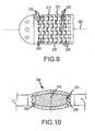
- tip element 210 is comprised of a single member that is formed into a helix, or spiral, and extends from tip electrode 208 to coupler 220.
- Tip element 210 includes a helically shaped body 230 having alternately spaced projections 232 extending away from body 230 in opposite directions from one another along the length of the helix. That is, a first set of projections 234 extends distally, i.e., towards tip electrode 208, and a second set of projections 236 extends proximally, i.e., away from tip electrode 208.
- the first set of projections 234 are staggered or offset from the second set of projections 236 such that the first set of projections 234 are offset from, and positioned between, the second set of projections 236.
- Recesses 238 extend between projections 232 and are complementary in shape to an outer contour of projections 232, but inversely shaped from projections 232.
- projections 232, and recesses 238, are trapezoidal in shape, although it is contemplated that other shapes could likewise be utilized in alternative embodiments.
- Tip element 210 is fabricated such that projections 232 from one section of body 230 extend into, and are captured within, recesses 238 from an adjacent section of body 230 to form an interlocking arrangement. Due to projections 232 being complementary in shape to recesses 238 and thus defining sockets or compartments for projections 232, projections 232 are movable only a defined distance within recesses 238. In particular, and as shown in Figure 9 , tip element 210 is positionable to create a space or gap 240 between leading edges of projections 232 and inner edges of recesses 238.
- Projections 232 and recesses 238 of tip element 210 extend completely along the length of body 230 and, in one embodiment, are uniformly spaced and sized around a perimeter of body 230. Alternatively, projections 232 and recesses 238 may be differently sized and/or spaced around the perimeter of body 230.
- tip element 210 can move toward and away from each other a defined distance to decrease and increase, respectively, gaps 240. It is thus possible for sections of tip element 210 to move relative to one another in multiple ways. For example, tip element 210 may be compressed so that all of gaps 240 are closed, or nearly closed, to reduce the longitudinal length of tip assembly 202 by the cumulative dimensions of gaps 240 along a longitudinal axis 242.
- sections of tip element 210 may exhibit cascaded or sequential movement along longitudinal axis 242 wherein some gaps 240 are closed along longitudinal axis 242 while other gaps remain open, either partially or fully. This allows gaps 240 between any adjacent sections of tip element 210 to be opened or closed in an uneven or non-uniform manner. As such, gaps 240 on one side of tip assembly 202 may be closed while gaps 240 on the other side of tip assembly 202 may be opened. The result of this configuration is that tip assembly 202 curves in the direction of the closed gaps 240 and away from the direction of the opened gaps 240.
- Tip assembly 202 may deflect in the manner described due to, for example, impact forces on an outer surface of tip assembly 202 in use, and may also, in whole or in part, be the result of the magnetic response of positioning magnet 222 (shown in Figure 8 ) and magnets 204 and 206 (shown in Figure 7 ).
- tip element 210 is laser cut from a material suitable for surgical use, such as an electrically conductive, non-corrosive material.
- the material is platinum.
- the material is stainless steel.
- Projections 232 and recesses 238 of tip element 210 are, in the exemplary embodiment, laser cut out of a cylindrical piece of material. It should be evident that as the number of helices increases in tip element 210, the flexing capability also increases. In addition, as the pitch of the helix decreases, the ability of tip element 210 to move relative to itself increases. The flexibility may further be adjusted by providing different numbers and shapes of projections and recesses to produce tip assemblies that flex to varying degrees to meet different objectives.
- RF energy may be more specifically targeted to desired tissue areas for ablation procedures when tip element 212 is flexed than when it is not flexed, and provides a physician with additional positioning capability over conventional catheter devices.
- tip assembly includes a plurality of adjacent rings that extend along longitudinal axis 242.
- Each ring has a distal side and a proximal side and each side includes alternating projections and recesses.
- This structure provides for flexibility in a manner that is similar to the exemplary embodiment described above. In such a configuration, the rings are constructed substantially identically to each other.
- Tip assembly 212 is particularly suited for ablation procedures wherein electrode 208 is energized to deliver radio frequency waves at the site of an abnormal electrical pathway in the body. Radiofrequency (RF) energy may therefore be applied to biological tissue in proximity to tip assembly 212. Ablation procedures are typically used, for example, within the interior chambers of the heart to thermally ablate cardiac tissue. Electrode 208 may additionally be operated to record intracardiac signals and to provide pacing signals. It should be noted that tip assembly 212 is also suited for recording of intracardiac signals and to provide pacing signals. While formed as an integral unit, tip electrode 208 may include multiple electrode elements, such as ring electrodes for electrophysiological mapping purposes, spaced from one another by dielectric materials as is known in the art.
- Figure 10 illustrates a magnet assembly 244 for catheter 200 (shown in Figure 7 ).
- magnet 204 is outwardly flared and has a generally ellipsoidal contour. That is, the outer diameter of magnet 204 is largest at an axial midpoint 246 and decreases from midpoint 246 to opposing ends 248, 250 of magnet 204, providing magnet 204 with a curved profile along an axial length of magnet 204.
- magnet 204 is encapsulated in sockets formed into adjacent tube portions as described above.
- magnet 204 is encapsulated in a sleeve that extends from the tube portions to cover magnet 204.
- magnet 204 includes a central bore through which a tube passes.
- Magnet 204 is formed from, for example, neodymium-iron boron - 45 (NdFeB-45) into the illustrated shape or an alternative shape. It should be understood that magnet 206 (shown in Figure 7 ) may be formed in the same shape as or a different shape from magnet 204.
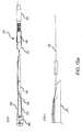
- Figure 11 illustrates a distal portion of catheter 200 in an exemplary operating position that shows the deflection of tip assembly 212 and magnets 204 and 206.
- the distal portion of catheter 200 may be precisely positioned at a specific location within the patient's body.
- the magnetic fields may be generated and controlled by, for example, a magnetic stereotactic system (not shown).
- Figure 12 illustrates a distal portion of an alternative catheter, such as a catheter 260.
- a distal portion of catheter 260 is shown in an exemplary operating position in which the deflection is caused by tip assembly 212 and magnets 106 and 108.
- the distal portion of catheter 260 may be precisely positioned at a specific location within the patient's body.
- the magnetic fields may be generated and controlled by, for example, a magnetic stereotactic system (not shown).
- the external positioning magnets of catheters 100, 200, and 260 are believed to provide manufacturing benefits, and also performance benefits, in relation to conventional, and more complicated, catheter constructions for use with stereotactic systems. Larger positioning magnets are provided for increased magnetic response and performance, and tubing is used that is generally smaller in internal diameter than the magnets, thereby resulting in material savings in comparison to known catheters having larger tubing to accommodate the magnets. In addition, increased flexibility is provided. Sockets in the tubes encapsulate the external positioning magnets in a very manufacturable and generally low cost construction. The external positioning magnets that are separately provided from the electrode tips also reduce a complexity and parts count in the tip assembly relative to other known catheter tips providing comparable functionality.
- FIG. 13 illustrates an exemplary manufacturing process for the magnetic guided catheter.
- Tubing 102 is a unitary tubing that is unitary in construction and formed as a single tubing prior to placing the magnets inside.
- magnets 106 and 108 may be pushed into tubing 102 during the manufacture process in the direction illustrated by arrow 103.
- magnets 106 and 108 may be positioned on mandrels 101 and 105, respectively, and pushed into tubing 102 one at a time using a lubricant such as, alcohol, to facilitate receiving magnets 106 and 108 therein. The alcohol conveniently evaporates after a short time.
- Magnets 106 and 108 are shown mounted on mandrels 101 and 105 outside of tubing 102. Magnets 106 and 108 are inserted into tubing 102 one at a time, by pushing mandrels 101 and 105 separately and sequentially in the direction of arrow 103.
- the interference fit may be formed by an outer diameter of the at least one magnet being larger than an inner diameter of the unitary flexible tubing.
- the interference fit may be formed by magnets 106 and 108 having an outer diameter about 0,127 mm (0.005 inches) larger than the inner diameter of tubing 102.
- magnets 106 and 108 may be pushed into tubing 102 without any interference fittings.
- tubing 102 may be wrapped in heat-shrink film or heat-shrink tubing. The heat-shrink process shrinks the heat-shrink film or tubing around tubing 102 so that the position of magnets 106 and 108 is secured within tubing 102.
- Heat-shrink processes are well understood in the arts. For purposes of discussion, however, the process may implement any of a wide variety of commercially available heat shrink film or tubing. Magnets 106 and 108 are first positioned within the heat shrink tubing. The magnets are readily positioned while the heat shrink tubing is in an initial state (e.g., at room temperature) prior to processing. Optionally, the magnet may be pretreated with a coating, e.g., to reduce the effects of corrosion. Application of heat to the heat shrink film or tubing shrinks the film or tubing around magnets 106 and 108. Shrinkage of the tubing around the magnet applies the necessary pressure to maintain magnets 106 and 108 in the desired position within tubing 102 after the heat shrink film or tubing cools.
- catheter 100 can be constructed to have different flexibilities along the length of tubing 102, particularly in the distal region where the magnets are placed.
- portion 126 shown in Figure 1
- first magnet 106 is desired to be the most flexible.
- Portion 124 between first magnet 106 and second magnet 108 disposed proximally from first magnet 106 is desired to have less flexibility.
- Still additional portions and additional magnets may be provided, with the proximal portions having less and less flexibility.
- the flexibility can be determined by material properties and/or thickness.
- unitary tubing 102 can be made to have varying material properties along its length toward the distal end, so that the different portions will have different flexibilities.
- the shaft can also decrease in thickness toward the distal end. A thinner wall of tubing 102 results in greater flexibility, while a thicker wall of tubing 102 results in less flexibility.
- Flexibility can change either continuously/gradually or in abrupt steps between the portions.
- the abrupt steps may be useful in defining the locations of the magnets, especially in the embodiment where the magnets are pushed into the shaft with a lubricant.
- the abrupt change in flexibility provides tactile feedback that magnets 106 and 108 are passing from one flexibility zone to another.
- the unitary construction of the flexible tubings of catheters 100 and 200 is believed to provide manufacturing benefits, and also performance benefits, in relation to conventional, and more complicated, catheter constructions for use with stereotactic systems.
- the catheter can be manufactured without requiring magnet-shaft fusion and without joints, ensuring high reliability and safety of the catheter.
- the unitary tubing is easier to manufacture, takes less time to manufacture, and does not require an expensive and complicated fusion machine. Eliminating the junction of the magnet and the shaft also reduces or altogether eliminates undesirable stiffness.
- the magnets that are separately provided from the electrode tips also reduces complexity and parts count in the tip assembly relative to other known catheter tips providing comparable functionality.
- the unitary flexible tubing may extend along substantially the entire length of the catheter body, and may have a distal end to be coupled to an electrode assembly and a proximal end to be coupled to a handle.
- the unitary flexible tubing may extend along a portion of the catheter body with no fused connections between the magnets, but may be attached to additional components to form the entire length of the catheter body.
- the unitary flexible tubing containing the magnets with no fused connections may be fused with another flexible tubing to form the entire length of the catheter body.
- Figures 14a-b illustrate another exemplary magnetic guided catheter 300, wherein Figure 14b is a magnified view of the distal end portion shown in Figure 14a showing exemplary spacing of the magnets 344, 306, and 308 and multiple sections of shafts numbered with triangle labels.
- the exemplary magnetic guided catheter 300 is similar in many aspects to catheters 100 and 200 described above. Therefore, like components and features of catheters 100 and 200 are indicated with like reference numbers using the 300-series, and not all reference numbers will be described again for the embodiment 300. Unlike catheters 100 and 200, however, catheter 300 includes different spacing of the magnets (see Figure 14b ); and a tip assembly 304 (see Figures 16a-d ) is different from the tip assembly 104 and distal end portion 202 described above. Other differences are also described in more detail below.
- Exemplary single-use magnetically guided catheter 300 generally includes a flexible outer tube, or tubing, 302, a tip assembly 304, three positioning magnets (304, 306 and 308) separately provided from and spaced from tip assembly 304.
- Catheter 300 may also include a Y-connector 310, and although not shown, a luer device, and an electrical connector, similar to that described above for catheter 100; to perform, for example, ablation procedures, mapping or pacing procedures, or to perform other aspects of a medical procedure.
- tubing 302 is fabricated from a tubing material defining a number of portions (see Figure 14b ). As already described above, the different relative lengths of these tube portions, the different flexible properties of tube portions, as well as the number and spacing of magnets, allow tip assembly 304 to be more precisely positioned within a patient's body, while also avoiding problems of kinks and excessive deflection of tubing 302 along the majority of its length during use and handling.
- these portions are fabricated from different materials and grades of materials for enhanced performance of tubing 302 in use of catheter assembly 300.
- the distal flexible portions (non-braided sections) of catheter 300 are manufactured of six durometers 0,67 mm (two French) sizes tubing (as opposed to the three durometers, 0,33 mm (one French) size tubing used for catheter 100). This sizing of the catheter body provides better transition of soft-to-stiff flexibility and enables the catheter 300 to be more readily pushed during deployment into proximity to a volume of target tissue through, for example, a relatively stiff introducer or hollow sheath. Once deployed to a location near the target tissue(s), the essentially flaccid distal tip portion then can be readily guided by the external magnetic fields of a stereotactic system.
- Tubing 302 may also be defined by the portions indicated by the numbered triangles in Figure 14b .
- the portions may have the following lengths: portion 1 (30mm between adjacent edges of the magnets), portion 2 (15mm between adjacent edges of the magnets), portion 3 (19mm), portion 4 (51mm), portion 5 (51mm), and portion 8 (51mm).
- This spacing of the magnets e.g., about 30mm-15mm
- the invention is not limited to these examples, and other relative lengths of the tube portions may likewise be employed in other embodiments.
- fewer or more tube portions and magnets could be used.
- tubing 302 is shown having separate sections or portions, in an exemplary embodiment, the tubing 302 is formed as a unitary length of tubing. In this regard, the tubing 302 is similar to the tubing described above with reference to Figure 13 .
- the magnets 344, 306 and 308 may be "pushed" or press-fit into the tubing 302 during manufacture, as already described above with reference to Figure 13 .
- Figure 15a is a cross sectional side view of the distal end portion of the magnetic guided catheter shown in Figures 14a-b ; and Figure 15b is a cross sectional view taken along lines A-A in Figure 15a .
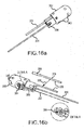
- Figures 16a and 16b illustrate the distal end portion of the magnetic guided catheter 300 shown in Figures 14a-b , wherein (a) is a first perspective view with partial tip assembly, and (b) is a second perspective view with partial cut-away showing internal detail of a tip electrode 350 where a safety wire 382 may be attached.
- tip assembly 304 includes a tip electrode 350, a coupler 352, a band electrode 354, first positioning magnet 344, and a temperature sensor 356 (see Figures 16a-b ).
- Lead wires 358, 360 extend to tip electrode 350, and to band electrode 354 on first respective ends thereof, and to the connector (e.g., connector 114 shown in Figure 1 ) on the second ends so that electrodes 350 and 354 may be energized by a power source (not shown).
- tip electrode 350 may be, for example a 2,3 mm (7 Fr) hemispherical-shaped tip electrode that is 4 mm in length.
- tip electrode 350 is fabricated from 90% platinum and 10% iridium, or other materials known in the art such that tip electrode 350 is viewable under fluoroscopic exposure. While formed as an integral unit, tip electrode 350 may include multiple electrode elements, such as ring electrodes for electrophysiological mapping purposes, spaced from one another by dielectric materials as is known in the art.
- the catheter may also be 'tracked' (localized position, configuration of shaft, and/or orientation) using magnetically-activated coils, such as those commercially available from Biosense Webster (e.g., the Carto system) or St. Jude Medical (e.g., the MediGuide magnetic position and orientation, or P&O, system), or with the St. Jude Medical EnSite NavX-compatible electrodes disposed along the length of the catheter shaft.
- Biosense Webster e.g., the Carto system
- St. Jude Medical e.g., the MediGuide magnetic position and orientation, or P&O, system
- St. Jude Medical EnSite NavX-compatible electrodes disposed along the length of the catheter shaft.
- Inner tube 316 forms a fluid lumen which connects directly to a plurality of openings that form irrigation ports 340 (see also Figures 16a-b ), e.g., for saline irrigation. For example, two rows may be provided having six irrigation ports 340 in each row, although other configurations are also contemplated.
- Inner tube 316 is different than inner tube 116 in that the inner tube 316 is manufactured with a larger inner diameter/outer diameter (ID/OD) non-braided Pebax tube to provide better flexibility and lower flow backpressure for proper pump operation. This design helps to reduce or altogether eliminate direct contact of saline fluid with the positioning magnet 344, increasing corrosion-resistance of the magnet 344. Of course, it is noted that the catheter 300 does not need to be irrigated.
- Coupler 352 is also different from the coupler 152 in a number of aspects.
- the coupler 352 is not external, but rather is internal of the catheter shaft. This design reduces machined part cost, and also increases the corrosion-resistance of the magnet 344.
- the coupler 352 is a cylindrical, electrically nonconductive member. It is typically made of a polymer such as Polyimide, which is relatively rigid and has a limited amount of flexibility and resiliency to form a snap-fit connection, for example.
- Coupler 352 includes a first end 370 coupled to the tip electrode 350, and a second end 372 that allows the magnet 344 to be pressed in partially. The coupler is fitted within first end 330 of tube portion 326. Additionally, or alternatively thereto, the first end 370 of coupler 352 is adhered to tip electrode 350, and the outer diameter of coupler 352 is adhered to the inner diameter of tube portion 326. Heat shrink techniques or adhesives may also be utilized to permanently attach coupler 352 to tube portion 326 and/or tip electrode 350.
- Positioning magnet 344 is disposed by pressing in partially at the end 372 of coupler 352.
- the positioning magnet 344 may be manufactured of any suitable material and have any suitable dimensions.
- the magnet 344 has a length of 9,525 mm (0.375 inches).
- the 50% length increase in size (as compared to the size of positioning magnet 144) provides higher magnetic deflecting force/moment to the distal portion of catheter 300.
- tip positioning magnet 344 is a generally cylindrical shaped permanent magnet fabricated from a known magnetic material, such as neodymium-iron boron - 45 (NdFeB-45).
- magnet 344 is formed from other materials and may have shapes different from the elongated cylindrical shape illustrated.
- a sectional coil spring 380 in the shaft is compressed between any two adjacent magnets and between the magnet 308 and the fused joint 399 of shaft tubing 302 (see Fig.14b ) to help maintain the positions of all magnets.
- the compression of each sectional spring serves to reduce shaft kinking tendency during insertion, pushing and deflecting of the catheter 300 in the patient's body.
- lead wires 358, 360, and a lead wire 378 for the temperature sensor 356 pass through a space defined between the inner tubing 316 and the magnet 344.
- Temperature sensor 356 is, in one embodiment, a thermocouple type temperature sensor, and lead wires 358, 360, and 378 are, for example, 38 AWG copper wires having quad polyimide insulation. It is noted that in Figure 16b , the temperature sensor 356 and lead wire 378 are shown in the top portion of the figure separately from the electrode tip 350 for purposes of illustration; and also shows lead wire 378 positioned in the electrode tip 350 (e.g., as illustrated there between by arrow 355).
- Catheter 300 may also include a safety wire 382 provided for the tip electrode 350.
- the safety wire 382 serves as additional assurance that the tip electrode 350 does not disconnect from the catheter 300 when the catheter 300 is inside of the patient's body.
- a high tensile strength LCP (liquid crystal polymer) fiber wire may be used as the safety wire 382.
- One end of the safety wire 382 may be affixed in the Y-connector 310, for example, using an anchor pin. The straightness/tension of the safety wire 382 may thus be fine tuned at the catheter handle.
- the safety wire 382 may also be affixed at the other end to the tip electrode 350.
- the safety wire 382 is affixed to the tip electrode 350 by tying a knot 384 in the end of the safety wire 382 and press-fitting the knotted end into a hole 386 drilled into the tip electrode 350 (see detail shown within Figure 16b ). Adhesive is then applied to bond the knot 384 and wire into the hole 386 of tip 350.
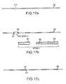
- Figures 17a-c illustrate exemplary assembly of the different sections or portions of the magnetic guided catheter shown in Figures 14a-b .
- a multiflex shaft 302 is cut, and the larger inner diameter tubing is cut to length.
- one end 391 of the cut shaft 302 is flared and the other end 392 of the cut shaft 302 is shaved, as shown in the detail in Figure 17b . Then the flared end 392 is overlapped onto the shaved end 391 of the shaft 302 and fused.
- the shaft 302 is prepared for assembly to the previously extended multiplex shaft. Additional portions may be similarly joined.
- Figures 18a-b illustrate exemplary assembly of magnets in the magnetic guided catheter 300 shown in Figures 14a-b .
- a first spring 380a is inserted into the shaft 302, followed by the first magnet 308, and each is pushed to a desired location (e.g., distance D1 from the distal end) and oriented with the desired polarity.
- a second spring 380b is inserted into the shaft 302, followed by the second magnet 306, and each is pushed to a desired location (e.g., distance D2 from the first magnet 308).
- the positioning magnet 344 is shown as it may be pressed into the coupler 352 to the desired location.
- the second end 372 of the coupler 352 is fitted within first end 330 of tube portion 302.
- a hole or opening 388 may be formed through one wall of the catheter shaft and the second end 372 of the coupler 352 to accommodate the lead wire 360 for the band electrode 354.
- a thin layer of adhesive may be applied to the band where the band electrode 354 is to be placed.
- the distal portion of the catheter tube may then be cut flush with the coupler 352, as shown in Figure 18b .
- a syringe 390 is also illustrated in Figure 18b as it may be used to insert an adhesive between the second end 372 of the coupler 352 and the catheter shaft or tubing 302. It is noted that one or more of the magnets could be electromagnets that are controllably pole-switched and/or turned magnetically 'off.'
- Figure 19 illustrates exemplary assembly of a tip electrode 350 to the distal end portion of the magnetic guided catheter 300 shown in Figures 14a-b .
- a one-half inch lumen end is split and the wires are bonded to the split with 12,7 mm (a one-half inch) extra length of safety wire.
- the flat end of a pull string 386 is bonded to the safety wire.
- a lubricant 388 e.g., silicon
- the top assembly wire is inserted and pulled through the shaft of the catheter 300, preferably without any twisting or rotation. The distal inner diameter of the shaft may then be cleaned.
- an adhesive may be applied to the tip electrode 350, and the tip electrode 350 is then slid onto and mounted to the shaft of the catheter 300.
Claims (14)
- Katheter (300), mit
einem flexiblen Rohr (302), das ein proximales Ende und ein distales Ende aufweist,
einer Elektrodengruppe (304), die an das distale Ende des flexiblen Rohrs (302) angebracht ist, bei dem die Elektrodengruppe (304) eine elektrisch leitfähige Spitzenelektrode (350) enthält,
einer Kupplung, die zwischen der Spitzenelektrode (350) und dem distalen Ende des flexiblen Rohrs (302) verbindet, wobei die Kupplung (352) und die Spitzenelektrode (350) durch eine Verriegelungsverbindung gekoppelt sind, wobei die Kupplung (352) ein erstes Ende (371), das an die Spitzenelektrode (350) gekoppelt ist, und ein zweites Ende (372) aufweist, wobei die Kupplung in das distale Ende des flexiblen Rohrs (302) gepasst ist,
einem ersten Magnet (344),
einem Fluidlumen, das sich durch das flexible Rohr (302) zu der Kupplung (352) erstreckt, wobei sich das Fluidlumen komplett durch den ersten Magneten (344) erstreckt und zumindest mit einer Öffnung (340), die in der Elektrodengruppe (304) ausgebildet ist, verbindet, und
einem zweiten Magnet (306), der von der Elektrodengruppe (304) entlang einer Längsachse des Rohrs (302) beabstandet ist,
wobei der erste Magnet (344) und der zweite Magnet (304) auf ein externes magnetisches Feld ansprechbar sind, um die Elektrodengruppe (304) innerhalb eines Körpers eines Patienten selektiv zu positionieren und zu führen,
dadurch gekennzeichnet, dass der erste Magnet (344) teilweise pressgepasst in das zweite Ende (372) der Kupplung (352) ist, so dass ein Ende des ersten Magnets (344) sich aus der Kupplung (352) erstreckt. - Katheter (300) nach Anspruch 1, bei dem die Kupplung eine interne Kupplung aufweist, und die Verriegelungsverbindung durch Koppeln eines ringförmigen Vorsprungs an die Spitzenelektrode und einer Nut an der Kupplung (352) ausgebildet wird, und wobei ein Klebstoff auf die Verriegelungsverbindung aufgebracht wird.
- Katheter (300) nach Anspruch 1 oder 2, bei dem die Verriegelungsverbindung eine Schnappverbindung ist.
- Katheter (300) nach einem der Ansprüche 1 bis 3, bei dem die Elektrodengruppe (304) weiter eine Bandelektrode (354) auf einer äußeren Oberfläche der Kupplung (352) aufweist, und die Bandelektrode (354) von der Spitzenelektrode (350) beabstandet ist und von dem ersten Magneten (344) versetzt ist.
- Katheter (300) nach einem der Ansprüche 1 bis 4, bei dem zumindest ein Draht (358, 360, 378, 382) zwischen dem Fluidlumen und einem inneren Durchmesser des ersten Magneten (344) vorgesehen ist, wobei der zumindest eine Draht (358, 360, 378, 382) generell in eine Längsrichtung orientiert ist.
- Katheter (300) nach einem der Ansprüche 1 bis 5, der weiter ein Lumen (316) aufweist, das durch den ersten Magneten (344) und den zweiten Magneten (308) passiert, und in Fluidverbindung mit der Elektrodengruppe (304) ist, bei dem die Elektrodengruppe (304) zumindest eine Reihe von Irrigationsöffnungen (340) aufweist, und die zumindest eine Reihe zumindest sechs Irrigationsöffnungen (340) aufweist, oder die Elektrodengruppe (304) zumindest zwei Reihen von Irrigationsöffnungen (340) aufweist, die längs voneinander beabstandet sind, und jede Reihe zumindest sechs Irrigationsöffnungen (340) aufweist.
- Katheter (300) nach einem der Ansprüche 1 bis 6, bei dem der zweite Magnet (306) einen äußeren Durchmesser aufweist, der größer als ein äußerer Durchmesser des flexiblen Rohrs (302) an einer von dem zweiten Magneten (306) beabstandeten Stelle ist, und bei dem das flexible Rohr (302) einen ersten äußeren Durchmesser und einen zweiten äußeren Durchmesser aufweist, und der zweite äußere Durchmesser größer als der erste äußere Durchmesser ist und den zweiten Magneten (306) überlagert.
- Katheter (300) nach einem der Ansprüche 1 bis 7, der weiter einen dritten Magneten (308) aufweist, der von dem zweiten Magneten (306) durch einen ersten Abstand entlang der Längsachse des flexiblen Rohrs (302) separiert ist, wobei der zweite Magnet (306) von der Elektrodengruppe (304) durch einen zweiten Abstand entlang der Längsachse des flexiblen Rohrs (302) beabstandet ist, und der erste Abstand größer als der zweite Abstand ist.
- Katheter (300) nach einem der Ansprüche 1 bis 8, bei dem ein Teil des flexiblen Rohrs (302) distal zu dem zweiten Magneten (306) flexibler als ein anderer Teil des flexiblen Rohrs (302) proximal zu dem zweiten Magneten (306) ist.
- Katheter (300) nach einem der Ansprüche 1 bis 9, bei dem das flexible Rohr (302) ein unitäres Rohr aufweist, und bei dem der zweite Magnet (306) im Inneren des flexiblen Rohrs (302) platziert wird, nachdem das unitäre flexible Rohr ausgebildet ist.
- Katheter (300) nach Anspruch 10, bei dem der zweite Magnet (306) in das unitäre flexible Rohr (302) mit einem mechanischen Interferenzsitz dazwischen eingedrückt wird.
- Katheter (300) nach einem der Ansprüche 1 bis 11, der weiter einen Sicherheitsdraht (382) aufweist, der an ein erstes Ende an einem Handgriff des Katheters (300) gekoppelt ist und an einem gegenüberliegenden Ende an die Spitzenelektrode (350) gekoppelt ist.
- Katheter (300) nach Anspruch 10 oder 11, bei dem der Teil des unitären flexiblen Rohrs (302) distal zu dem zweiten Magnet (306) ein Material enthält, das flexibler als ein unterschiedliches Material in dem Teil des flexiblen Rohrs (302) proximal zu dem zweiten Magneten (306) ist.
- Katheter (300) nach Anspruch 12, bei dem der Sicherheitsdraht (382) an die Spitzenelektrode (350) durch Ausbilden eines Knotens in dem Sicherheitsdraht und Drücken des geknoteten Endes des Sicherheitsdrahtes (382) in ein Loch, das an der Spitzenelektrode (350) ausgebildet ist, verbunden wird.
Applications Claiming Priority (2)
| Application Number | Priority Date | Filing Date | Title |
|---|---|---|---|
| US12/723,110 US8734440B2 (en) | 2007-07-03 | 2010-03-12 | Magnetically guided catheter |
| PCT/US2011/027907 WO2011112814A1 (en) | 2010-03-12 | 2011-03-10 | Magnetically guided catheter |
Publications (3)
| Publication Number | Publication Date |
|---|---|
| EP2544749A1 EP2544749A1 (de) | 2013-01-16 |
| EP2544749A4 EP2544749A4 (de) | 2013-10-02 |
| EP2544749B1 true EP2544749B1 (de) | 2015-08-12 |
Family
ID=44563844
Family Applications (1)
| Application Number | Title | Priority Date | Filing Date |
|---|---|---|---|
| EP11754076.5A Active EP2544749B1 (de) | 2010-03-12 | 2011-03-10 | Magnetisch geführter katheter |
Country Status (5)
| Country | Link |
|---|---|
| US (1) | US8734440B2 (de) |
| EP (1) | EP2544749B1 (de) |
| JP (1) | JP5753862B2 (de) |
| CN (1) | CN102892453B (de) |
| WO (1) | WO2011112814A1 (de) |
Cited By (1)
| Publication number | Priority date | Publication date | Assignee | Title |
|---|---|---|---|---|
| US11850051B2 (en) | 2019-04-30 | 2023-12-26 | Biosense Webster (Israel) Ltd. | Mapping grid with high density electrode array |
Families Citing this family (88)
| Publication number | Priority date | Publication date | Assignee | Title |
|---|---|---|---|---|
| DE60336914D1 (de) | 2002-08-24 | 2011-06-09 | Atrial Fibrillation Division Inc | Verfahren und gerät zur lokalisierung der fossa ovalis und durchführung einer transseptalen punktion |
| US8784336B2 (en) | 2005-08-24 | 2014-07-22 | C. R. Bard, Inc. | Stylet apparatuses and methods of manufacture |
| US7794407B2 (en) | 2006-10-23 | 2010-09-14 | Bard Access Systems, Inc. | Method of locating the tip of a central venous catheter |
| US8517999B2 (en) | 2007-04-04 | 2013-08-27 | St. Jude Medical, Atrial Fibrillation Division, Inc. | Irrigated catheter with improved fluid flow |
| US8187267B2 (en) * | 2007-05-23 | 2012-05-29 | St. Jude Medical, Atrial Fibrillation Division, Inc. | Ablation catheter with flexible tip and methods of making the same |
| US8979837B2 (en) | 2007-04-04 | 2015-03-17 | St. Jude Medical, Atrial Fibrillation Division, Inc. | Flexible tip catheter with extended fluid lumen |
| US8764742B2 (en) | 2007-04-04 | 2014-07-01 | St. Jude Medical, Atrial Fibrillation Division, Inc. | Irrigated catheter |
| US8734440B2 (en) | 2007-07-03 | 2014-05-27 | St. Jude Medical, Atrial Fibrillation Division, Inc. | Magnetically guided catheter |
| US8974454B2 (en) | 2009-12-31 | 2015-03-10 | St. Jude Medical, Atrial Fibrillation Division, Inc. | Kit for non-invasive electrophysiology procedures and method of its use |
| US10220187B2 (en) | 2010-06-16 | 2019-03-05 | St. Jude Medical, Llc | Ablation catheter having flexible tip with multiple flexible electrode segments |
| US11395694B2 (en) * | 2009-05-07 | 2022-07-26 | St. Jude Medical, Llc | Irrigated ablation catheter with multiple segmented ablation electrodes |
| US8206404B2 (en) | 2007-07-03 | 2012-06-26 | St. Jude Medical, Atrial Fibrillation Division, Inc. | Magnetically guided catheter |
| ES2832713T3 (es) | 2007-11-26 | 2021-06-11 | Bard Inc C R | Sistema integrado para la colocación intravascular de un catéter |
| US8849382B2 (en) | 2007-11-26 | 2014-09-30 | C. R. Bard, Inc. | Apparatus and display methods relating to intravascular placement of a catheter |
| US9649048B2 (en) | 2007-11-26 | 2017-05-16 | C. R. Bard, Inc. | Systems and methods for breaching a sterile field for intravascular placement of a catheter |
| US10524691B2 (en) * | 2007-11-26 | 2020-01-07 | C. R. Bard, Inc. | Needle assembly including an aligned magnetic element |
| US10751509B2 (en) | 2007-11-26 | 2020-08-25 | C. R. Bard, Inc. | Iconic representations for guidance of an indwelling medical device |
| US8781555B2 (en) | 2007-11-26 | 2014-07-15 | C. R. Bard, Inc. | System for placement of a catheter including a signal-generating stylet |
| US9521961B2 (en) | 2007-11-26 | 2016-12-20 | C. R. Bard, Inc. | Systems and methods for guiding a medical instrument |
| US10449330B2 (en) | 2007-11-26 | 2019-10-22 | C. R. Bard, Inc. | Magnetic element-equipped needle assemblies |
| US9901714B2 (en) | 2008-08-22 | 2018-02-27 | C. R. Bard, Inc. | Catheter assembly including ECG sensor and magnetic assemblies |
| US8437833B2 (en) | 2008-10-07 | 2013-05-07 | Bard Access Systems, Inc. | Percutaneous magnetic gastrostomy |
| US9445734B2 (en) | 2009-06-12 | 2016-09-20 | Bard Access Systems, Inc. | Devices and methods for endovascular electrography |
| US9532724B2 (en) | 2009-06-12 | 2017-01-03 | Bard Access Systems, Inc. | Apparatus and method for catheter navigation using endovascular energy mapping |
| AU2010300677B2 (en) | 2009-09-29 | 2014-09-04 | C.R. Bard, Inc. | Stylets for use with apparatus for intravascular placement of a catheter |
| CN102821679B (zh) | 2010-02-02 | 2016-04-27 | C·R·巴德股份有限公司 | 用于导管导航和末端定位的装置和方法 |
| EP4122385A1 (de) | 2010-05-28 | 2023-01-25 | C. R. Bard, Inc. | Einsatzführungssystem für nadeln und medizinische komponenten |
| EP2912999B1 (de) | 2010-05-28 | 2022-06-29 | C. R. Bard, Inc. | Vorrichtung zur Verwendung mit einem Nadeleinsatz-Führungssystem |
| US9023033B2 (en) * | 2010-08-04 | 2015-05-05 | St. Jude Medical, Atrial Fibrillation Division, Inc. | Magnetically guided catheters |
| US8532743B2 (en) | 2010-08-05 | 2013-09-10 | St. Jude Medical, Atrial Fibrillation Division, Inc. | Movable magnet for magnetically guided catheter |
| KR101856267B1 (ko) | 2010-08-20 | 2018-05-09 | 씨. 알. 바드, 인크. | Ecg-기반 카테터 팁 배치의 재확인 |
| WO2012058461A1 (en) | 2010-10-29 | 2012-05-03 | C.R.Bard, Inc. | Bioimpedance-assisted placement of a medical device |
| US9788891B2 (en) | 2010-12-28 | 2017-10-17 | St. Jude Medical, Atrial Fibrillation Division, Inc. | Ablation electrode assemblies and methods for using same |
| US8979840B2 (en) | 2010-12-17 | 2015-03-17 | St. Jude Medical, Atrial Fibrillation Division, Inc. | Irrigant distribution system for flexible electrodes |
| US9855094B2 (en) | 2010-12-28 | 2018-01-02 | St. Jude Medical, Atrial Fibrillation Division, Inc. | Multi-rate fluid flow and variable power delivery for ablation electrode assemblies used in catheter ablation procedures |
| EP2615990B1 (de) * | 2011-06-16 | 2020-08-19 | St. Jude Medical Atrial Fibrillation Division Inc. | Spülflüssigkeitsverteilungssystem für flexible elektroden |
| EP2729073A4 (de) | 2011-07-06 | 2015-03-11 | Bard Inc C R | Nadellängenbestimmung und -kalibrierung für ein einsatzführungssystem |
| US9801683B2 (en) * | 2011-07-29 | 2017-10-31 | St. Jude Medical, Atrial Fibrillation Division, Inc. | Universal shaft for magnetic manipulation of catheters |
| US8945025B2 (en) | 2011-12-30 | 2015-02-03 | St. Jude Medical, Atrial Fibrillation Division, Inc. | Catheter with atraumatic tip |
| US20130225996A1 (en) * | 2012-02-28 | 2013-08-29 | Spiration, Inc. | Lung biopsy needle |
| US20130296691A1 (en) * | 2012-05-04 | 2013-11-07 | Ascension Technology Corporation | Magnetically tracked surgical needle assembly |
| US10004877B2 (en) | 2012-05-07 | 2018-06-26 | St. Jude Medical, Atrial Fibrillation Division, Inc. | Deflectable catheter shaft section, catheter incorporating same, and method of manufacturing same |
| US9861738B2 (en) | 2012-05-07 | 2018-01-09 | St. Jude Medical, Cardiology Division, Inc. | Flex tip fluid lumen assembly with termination tube |
| US9066725B2 (en) | 2012-12-06 | 2015-06-30 | St. Jude Medical, Atrial Fibrillation Division, Inc. | Irrigant distribution system for electrodes |
| US20140200639A1 (en) * | 2013-01-16 | 2014-07-17 | Advanced Neuromodulation Systems, Inc. | Self-expanding neurostimulation leads having broad multi-electrode arrays |
| US9605696B1 (en) * | 2013-01-17 | 2017-03-28 | David Glen May | Detachable magnetic retainers |
| JP5737765B2 (ja) * | 2013-02-28 | 2015-06-17 | 日本ライフライン株式会社 | カテーテルシステム |
| US10835183B2 (en) | 2013-07-01 | 2020-11-17 | Zurich Medical Corporation | Apparatus and method for intravascular measurements |
| WO2015003024A2 (en) | 2013-07-01 | 2015-01-08 | Zurich Medical, Inc. | Apparatus and method for intravascular measurements |
| CN107693112A (zh) * | 2013-11-15 | 2018-02-16 | 上海微创电生理医疗科技股份有限公司 | 消融电极以及具有该消融电极的医疗导管 |
| EP3073910B1 (de) | 2014-02-06 | 2020-07-15 | C.R. Bard, Inc. | Systeme zur führung und platzierung einer intravaskulären vorrichtung |
| JP6246383B2 (ja) | 2014-02-06 | 2017-12-13 | セント・ジュード・メディカル,カーディオロジー・ディヴィジョン,インコーポレイテッド | 面取りされたリング電極および可変シャフトを備えた細長医療機器 |
| US9848943B2 (en) * | 2014-04-18 | 2017-12-26 | Biosense Webster (Israel) Ltd. | Ablation catheter with dedicated fluid paths and needle centering insert |
| US10722140B2 (en) | 2014-07-03 | 2020-07-28 | St. Jude Medical International Holding S.À R.L. | Localized magnetic field generator |
| US9820664B2 (en) | 2014-11-20 | 2017-11-21 | Biosense Webster (Israel) Ltd. | Catheter with high density electrode spine array |
| US10034707B2 (en) * | 2014-12-30 | 2018-07-31 | Biosense Webster (Israel) Ltd. | Catheter with irrigated tip electrode with porous substrate and high density surface micro-electrodes |
| US10973584B2 (en) | 2015-01-19 | 2021-04-13 | Bard Access Systems, Inc. | Device and method for vascular access |
| JP6560762B2 (ja) | 2015-03-31 | 2019-08-14 | セント・ジュード・メディカル,カーディオロジー・ディヴィジョン,インコーポレイテッド | 高熱感受性アブレーション・カテーテル及びカテーテル・チップ |
| CN107405099B (zh) * | 2015-05-11 | 2021-02-09 | 圣犹达医疗用品心脏病学部门有限公司 | 高密度标测和消融导管 |
| US10349890B2 (en) | 2015-06-26 | 2019-07-16 | C. R. Bard, Inc. | Connector interface for ECG-based catheter positioning system |
| US9949656B2 (en) | 2015-06-29 | 2018-04-24 | Biosense Webster (Israel) Ltd. | Catheter with stacked spine electrode assembly |
| US10537259B2 (en) | 2015-06-29 | 2020-01-21 | Biosense Webster (Israel) Ltd. | Catheter having closed loop array with in-plane linear electrode portion |
| US10575742B2 (en) | 2015-06-30 | 2020-03-03 | Biosense Webster (Israel) Ltd. | Catheter having closed electrode assembly with spines of uniform length |
| CN104983462A (zh) * | 2015-07-02 | 2015-10-21 | 安隽医疗科技(南京)有限公司 | 一种射频消融双极导管以及包含该射频消融双极导管的治疗装置 |
| CN104970881A (zh) * | 2015-07-02 | 2015-10-14 | 安隽医疗科技(南京)有限公司 | 一种射频消融导管以及包含该射频消融导管的治疗装置 |
| CN105056371A (zh) * | 2015-08-17 | 2015-11-18 | 湖南埃普特医疗器械有限公司 | 导引鞘 |
| US11000207B2 (en) | 2016-01-29 | 2021-05-11 | C. R. Bard, Inc. | Multiple coil system for tracking a medical device |
| EP3432820B1 (de) * | 2016-05-03 | 2021-04-28 | St. Jude Medical, Cardiology Division, Inc. | Benetzter hochdichter elektrodenkatheter |
| US11344220B2 (en) * | 2016-05-13 | 2022-05-31 | Becton, Dickinson And Company | Invasive medical device cover with magnet |
| WO2018067248A1 (en) | 2016-10-04 | 2018-04-12 | St. Jude Medical, Cardiology Division, Inc. | Ablation catheter tip |
| US11172858B2 (en) | 2016-10-28 | 2021-11-16 | St. Jude Medical, Cardiology Division, Inc. | Flexible high-density mapping catheter |
| KR101805674B1 (ko) | 2017-02-09 | 2017-12-06 | 재단법인대구경북과학기술원 | 카테터 부착형 마이크로로봇 |
| CN106618471B (zh) * | 2017-02-22 | 2019-06-11 | 梁敏仪 | 纤维外周神经置管镜 |
| CN108720920B (zh) * | 2017-04-24 | 2019-07-09 | 四川锦江电子科技有限公司 | 具有与组织接触压力检测功能的消融导管 |
| CN110650676B (zh) * | 2017-05-23 | 2022-12-02 | 波士顿科学医学有限公司 | 用于接触力感测的导管与弹簧元件 |
| CN109568769A (zh) * | 2017-09-28 | 2019-04-05 | 四川锦江电子科技有限公司 | 一种用于导管旋转方向检测的方法和装置 |
| EP3658054B1 (de) | 2017-10-13 | 2023-03-22 | St. Jude Medical, Cardiology Division, Inc. | Katheter mit high-density-mapping-elektroden |
| US20210038861A1 (en) * | 2018-02-02 | 2021-02-11 | Microbot Medical Ltd. | Self-cleaning catheter systems with self-monitoring capabilities |
| US10945626B2 (en) * | 2018-02-06 | 2021-03-16 | Biosense Webster (Israel) Ltd. | Catheter with staggered electrodes spine assembly |
| DK180026B1 (en) * | 2018-03-12 | 2020-01-24 | Mbh-International A/S | A flexible double lumen tube and a tube coupling system for same |
| US11426111B2 (en) | 2018-03-13 | 2022-08-30 | St. Jude Medical, Cardiology Division, Inc. | Variable density mapping catheter |
| US20190350649A1 (en) | 2018-05-21 | 2019-11-21 | St. Jude Medical, Cardiology Division, Inc. | Radio-frequency ablation and direct current electroporation catheters |
| EP3790484A1 (de) | 2018-09-28 | 2021-03-17 | St. Jude Medical, Cardiology Division, Inc. | Spitzenelektrodenanordnungen für intravaskulären katheter |
| EP3852622A1 (de) | 2018-10-16 | 2021-07-28 | Bard Access Systems, Inc. | Sicherheitsausgerüstete verbindungssysteme und verfahren dafür zur herstellung von elektrischen verbindungen |
| NL2022093B1 (en) * | 2018-11-29 | 2020-06-26 | Sirius Medical Systems B V | The present disclosure relates to a magnetic field probe for determining a disposition of an implantable magnetic marker, a detection unit comprising the probe and a method of detecting the disposition of an implantable magnetic marker. |
| CN111068162B (zh) * | 2019-12-24 | 2022-02-15 | 四川锦江电子科技有限公司 | 导管进出鞘检测部件、方法以及电生理导管、导引鞘管 |
| CN116547031A (zh) * | 2020-11-17 | 2023-08-04 | 科里福罗公司 | 医用管清除装置 |
| CN113100940B (zh) * | 2021-04-09 | 2022-09-13 | 哈尔滨工业大学(深圳) | 一种多点磁控导管导航系统及其使用方法 |
Family Cites Families (115)
| Publication number | Priority date | Publication date | Assignee | Title |
|---|---|---|---|---|
| US3470876A (en) * | 1966-09-28 | 1969-10-07 | John Barchilon | Dirigible catheter |
| SE336642B (de) * | 1969-10-28 | 1971-07-12 | Astra Meditec Ab | |
| JPS5917290Y2 (ja) * | 1979-06-04 | 1984-05-21 | オリンパス光学工業株式会社 | 内視鏡用高周波ナイフ |
| US4809718A (en) * | 1987-05-06 | 1989-03-07 | R. J. Reynolds Tobacco Company | Variable air dilution cigarette filters |
| US4809713A (en) | 1987-10-28 | 1989-03-07 | Joseph Grayzel | Catheter with magnetic fixation |
| US4945912A (en) * | 1988-11-25 | 1990-08-07 | Sensor Electronics, Inc. | Catheter with radiofrequency heating applicator |
| US5056517A (en) | 1989-07-24 | 1991-10-15 | Consiglio Nazionale Delle Ricerche | Biomagnetically localizable multipurpose catheter and method for magnetocardiographic guided intracardiac mapping, biopsy and ablation of cardiac arrhythmias |
| US5163905A (en) * | 1990-01-12 | 1992-11-17 | Don Michael T Anthony | Regional perfusion dissolution catheter |
| US5156151A (en) * | 1991-02-15 | 1992-10-20 | Cardiac Pathways Corporation | Endocardial mapping and ablation system and catheter probe |
| US5363861A (en) * | 1991-11-08 | 1994-11-15 | Ep Technologies, Inc. | Electrode tip assembly with variable resistance to bending |
| US5585657A (en) * | 1992-04-16 | 1996-12-17 | Texas Instruments Incorporated | Windowed and segmented linear geometry source cell for power DMOS processes |
| US5269759A (en) * | 1992-07-28 | 1993-12-14 | Cordis Corporation | Magnetic guidewire coupling for vascular dilatation apparatus |
| DE4338758C2 (de) | 1992-11-13 | 2001-08-09 | Scimed Life Systems Inc | Katheteranordnung |
| US5545200A (en) * | 1993-07-20 | 1996-08-13 | Medtronic Cardiorhythm | Steerable electrophysiology catheter |
| US5582609A (en) * | 1993-10-14 | 1996-12-10 | Ep Technologies, Inc. | Systems and methods for forming large lesions in body tissue using curvilinear electrode elements |
| US5378230A (en) * | 1993-11-01 | 1995-01-03 | Mahurkar; Sakharam D. | Triple-lumen critical care catheter |
| US5487385A (en) | 1993-12-03 | 1996-01-30 | Avitall; Boaz | Atrial mapping and ablation catheter system |
| US5462521A (en) * | 1993-12-21 | 1995-10-31 | Angeion Corporation | Fluid cooled and perfused tip for a catheter |
| EP0774929A4 (de) * | 1994-07-22 | 2000-09-27 | Univ Washington | Verfahren zur stereotaktischen implantation |
| US6030382A (en) * | 1994-08-08 | 2000-02-29 | Ep Technologies, Inc. | Flexible tissue ablatin elements for making long lesions |
| US5706827A (en) * | 1994-09-21 | 1998-01-13 | Scimed Life Systems, Inc. | Magnetic lumen catheter |
| US6690963B2 (en) * | 1995-01-24 | 2004-02-10 | Biosense, Inc. | System for determining the location and orientation of an invasive medical instrument |
| US6053912A (en) * | 1995-05-01 | 2000-04-25 | Ep Techonologies, Inc. | Systems and methods for sensing sub-surface temperatures in body tissue during ablation with actively cooled electrodes |
| US5681280A (en) * | 1995-05-02 | 1997-10-28 | Heart Rhythm Technologies, Inc. | Catheter control system |
| US5782810A (en) * | 1995-11-22 | 1998-07-21 | O'donnell; Miles C. | Multipart radiopaque and/or magnetically detectable tube catheter and method of fabrication thereof |
| US5833632A (en) * | 1995-12-07 | 1998-11-10 | Sarcos, Inc. | Hollow guide wire apparatus catheters |
| US5755760A (en) * | 1996-03-11 | 1998-05-26 | Medtronic, Inc. | Deflectable catheter |
| US5800428A (en) | 1996-05-16 | 1998-09-01 | Angeion Corporation | Linear catheter ablation system |
| US20050245894A1 (en) * | 1996-05-20 | 2005-11-03 | Medtronic Vascular, Inc. | Methods and apparatuses for drug delivery to an intravascular occlusion |
| US5911720A (en) * | 1996-11-26 | 1999-06-15 | Ep Technologies, Inc. | Ablation catheter with segmented tip |
| US6235022B1 (en) * | 1996-12-20 | 2001-05-22 | Cardiac Pathways, Inc | RF generator and pump apparatus and system and method for cooled ablation |
| US5919188A (en) * | 1997-02-04 | 1999-07-06 | Medtronic, Inc. | Linear ablation catheter |
| US5782900A (en) * | 1997-06-23 | 1998-07-21 | Irvine Biomedical, Inc. | Catheter system having safety means |
| US6015414A (en) * | 1997-08-29 | 2000-01-18 | Stereotaxis, Inc. | Method and apparatus for magnetically controlling motion direction of a mechanically pushed catheter |
| US6273876B1 (en) * | 1997-12-05 | 2001-08-14 | Intratherapeutics, Inc. | Catheter segments having circumferential supports with axial projection |
| US6295990B1 (en) * | 1998-02-03 | 2001-10-02 | Salient Interventional Systems, Inc. | Methods and systems for treating ischemia |
| US7879022B2 (en) * | 1998-02-06 | 2011-02-01 | Medrad, Inc. | Rapid exchange fluid jet thrombectomy device and method |
| US5951471A (en) * | 1998-03-09 | 1999-09-14 | Irvine Biomedical, Inc. | Catheter-based coronary sinus mapping and ablation |
| US6122647A (en) * | 1998-05-19 | 2000-09-19 | Perspecta, Inc. | Dynamic generation of contextual links in hypertext documents |
| US6889089B2 (en) * | 1998-07-28 | 2005-05-03 | Scimed Life Systems, Inc. | Apparatus and method for treating tumors near the surface of an organ |
| US6385472B1 (en) * | 1999-09-10 | 2002-05-07 | Stereotaxis, Inc. | Magnetically navigable telescoping catheter and method of navigating telescoping catheter |
| US6185448B1 (en) * | 1998-09-29 | 2001-02-06 | Simcha Borovsky | Apparatus and method for locating and mapping a catheter in intracardiac operations |
| US6210406B1 (en) * | 1998-12-03 | 2001-04-03 | Cordis Webster, Inc. | Split tip electrode catheter and signal processing RF ablation system |
| US6464632B1 (en) * | 1999-02-13 | 2002-10-15 | James M. Taylor | Flexible inner liner for the working channel of an endoscope |
| US6251134B1 (en) * | 1999-02-28 | 2001-06-26 | Inflow Dynamics Inc. | Stent with high longitudinal flexibility |
| US6210409B1 (en) * | 1999-05-03 | 2001-04-03 | Alan G. Ellman | Electrosurgical handpiece for treating tissue |
| US6292678B1 (en) * | 1999-05-13 | 2001-09-18 | Stereotaxis, Inc. | Method of magnetically navigating medical devices with magnetic fields and gradients, and medical devices adapted therefor |
| US6126647A (en) | 1999-05-17 | 2000-10-03 | Hermetic Switch, Inc. | Magnetically guided catheter with sensor |
| US6235024B1 (en) * | 1999-06-21 | 2001-05-22 | Hosheng Tu | Catheters system having dual ablation capability |
| US6640130B1 (en) | 1999-07-02 | 2003-10-28 | Hypermed, Inc. | Integrated imaging apparatus |
| US6350253B1 (en) * | 1999-07-19 | 2002-02-26 | I-Flow Corporation | Catheter for uniform delivery of medication |
| US6702804B1 (en) * | 1999-10-04 | 2004-03-09 | Stereotaxis, Inc. | Method for safely and efficiently navigating magnetic devices in the body |
| US6493590B1 (en) * | 2000-02-09 | 2002-12-10 | Micronet Medical, Inc. | Flexible band electrodes for medical leads |
| US6401723B1 (en) * | 2000-02-16 | 2002-06-11 | Stereotaxis, Inc. | Magnetic medical devices with changeable magnetic moments and method of navigating magnetic medical devices with changeable magnetic moments |
| AU2001239964A1 (en) * | 2000-02-29 | 2001-09-12 | Johns Hopkins University | Circumferential pulmonary vein ablation using a laser and fiberoptic balloon catheter |
| US6669692B1 (en) * | 2000-08-21 | 2003-12-30 | Biosense Webster, Inc. | Ablation catheter with cooled linear electrode |
| WO2002019933A1 (en) * | 2000-09-07 | 2002-03-14 | Sherwood Services Ag | Apparatus for and treatment of the intervertebral disc |
| US6524303B1 (en) * | 2000-09-08 | 2003-02-25 | Stereotaxis, Inc. | Variable stiffness magnetic catheter |
| US6544270B1 (en) * | 2000-09-14 | 2003-04-08 | Cardiac Pacemakers, Inc. | Multi-lumen cardiac catheter and system |
| US6662034B2 (en) * | 2000-11-15 | 2003-12-09 | Stereotaxis, Inc. | Magnetically guidable electrophysiology catheter |
| US20030009094A1 (en) * | 2000-11-15 | 2003-01-09 | Segner Garland L. | Electrophysiology catheter |
| US6814718B2 (en) * | 2001-01-09 | 2004-11-09 | Rex Medical, L.P | Dialysis catheter |
| US20020103426A1 (en) * | 2001-01-29 | 2002-08-01 | Segner Garland L. | Electrophysiology catheter |
| EP1232977B1 (de) * | 2001-02-15 | 2004-07-07 | Ferag AG | Verfahren und Vorrichtung zum stückweisen Abbau eines Stapels flacher Gegenstände |
| US6969373B2 (en) * | 2001-04-13 | 2005-11-29 | Tricardia, Llc | Syringe system |
| US20020156420A1 (en) * | 2001-04-20 | 2002-10-24 | Anderson Mark L. | Fluid delivery cannula technology |
| US7276044B2 (en) * | 2001-05-06 | 2007-10-02 | Stereotaxis, Inc. | System and methods for advancing a catheter |
| US6611699B2 (en) * | 2001-06-28 | 2003-08-26 | Scimed Life Systems, Inc. | Catheter with an irrigated composite tip electrode |
| US6730082B2 (en) | 2001-07-09 | 2004-05-04 | Scimed Life Systems, Inc. | Two-piece distal catheter assembly |
| US6740083B2 (en) * | 2001-07-09 | 2004-05-25 | Scimed Life Systems, Inc. | Distal catheter assembly with proximal mounting member |
| US6733497B2 (en) * | 2001-07-09 | 2004-05-11 | Scimed Life Systems, Inc. | Clamshell distal catheter assembly |
| US6730062B2 (en) * | 2001-10-11 | 2004-05-04 | Medex, Inc. | Safety catheter with non-removable retractable needle |
| AU2002357166A1 (en) * | 2001-12-12 | 2003-06-23 | Tissuelink Medical, Inc. | Fluid-assisted medical devices, systems and methods |
| US7099717B2 (en) | 2002-01-03 | 2006-08-29 | Afx Inc. | Catheter having improved steering |
| US6817999B2 (en) * | 2002-01-03 | 2004-11-16 | Afx, Inc. | Flexible device for ablation of biological tissue |
| DE10203371A1 (de) | 2002-01-29 | 2003-08-07 | Siemens Ag | Katheter, insbesondere intravaskulärer Katheter |
| US7060024B2 (en) * | 2002-03-15 | 2006-06-13 | Ethicon Endo-Surgery, Inc. | Apparatus for guiding an instrument used with an endoscope |
| US6814731B2 (en) * | 2002-05-20 | 2004-11-09 | Scimed Life Systems, Inc. | Methods for RF ablation using jet injection of conductive fluid |
| US6945952B2 (en) * | 2002-06-25 | 2005-09-20 | Theraject, Inc. | Solid solution perforator for drug delivery and other applications |
| US7769427B2 (en) * | 2002-07-16 | 2010-08-03 | Magnetics, Inc. | Apparatus and method for catheter guidance control and imaging |
| US6893414B2 (en) * | 2002-08-12 | 2005-05-17 | Breg, Inc. | Integrated infusion and aspiration system and method |
| US6780183B2 (en) * | 2002-09-16 | 2004-08-24 | Biosense Webster, Inc. | Ablation catheter having shape-changing balloon |
| US20040153056A1 (en) * | 2002-11-11 | 2004-08-05 | Berchtold Holding Gmbh, A German Corporation | Probe |
| US8256428B2 (en) * | 2003-03-12 | 2012-09-04 | Biosense Webster, Inc. | Method for treating tissue |
| DE10313868B4 (de) * | 2003-03-21 | 2009-11-19 | Siemens Ag | Katheter zur magnetischen Navigation |
| US7182752B2 (en) * | 2003-04-08 | 2007-02-27 | Surgiquest, Incorporated | Continuous gas flow trocar assembly |
| US6980843B2 (en) * | 2003-05-21 | 2005-12-27 | Stereotaxis, Inc. | Electrophysiology catheter |
| US6921397B2 (en) * | 2003-05-27 | 2005-07-26 | Cardia, Inc. | Flexible delivery device |
| US20050004563A1 (en) * | 2003-07-01 | 2005-01-06 | Racz N. Sandor | Apparatus and methods for sensing and cooling during application of thermal energy for treating degenerative spinal discs |
| DE202004021944U1 (de) * | 2003-09-12 | 2013-07-16 | Vessix Vascular, Inc. | Auswählbare exzentrische Remodellierung und/oder Ablation von atherosklerotischem Material |
| NL1024658C2 (nl) | 2003-10-29 | 2005-05-02 | Univ Medisch Centrum Utrecht | Katheter en werkwijze, in het bijzonder voor ablatie en dergelijke techniek. |
| ES2552252T3 (es) * | 2004-03-23 | 2015-11-26 | Boston Scientific Limited | Sistema de visualización in vivo |
| AU2005229019A1 (en) | 2004-03-30 | 2005-10-13 | Cathrx Ltd | A catheter steering device |
| US20050245846A1 (en) * | 2004-05-03 | 2005-11-03 | Casey Don E | Vibrating, magnetically guidable catheter with magnetic powder commingled with resin, extruded as an integral part the catheter |
| US7389148B1 (en) * | 2004-05-05 | 2008-06-17 | Pacesetter, Inc. | Electrode design for defibrillation and/or sensing capabilities |
| US7481808B2 (en) * | 2004-06-30 | 2009-01-27 | Ethicon, Inc. | Flexible electrode device and surgical apparatus equipped with same |
| US8075498B2 (en) * | 2005-03-04 | 2011-12-13 | Endosense Sa | Medical apparatus system having optical fiber load sensing capability |
| US7857810B2 (en) * | 2006-05-16 | 2010-12-28 | St. Jude Medical, Atrial Fibrillation Division, Inc. | Ablation electrode assembly and methods for improved control of temperature and minimization of coagulation and tissue damage |
| US20080091193A1 (en) * | 2005-05-16 | 2008-04-17 | James Kauphusman | Irrigated ablation catheter having magnetic tip for magnetic field control and guidance |
| US8027714B2 (en) * | 2005-05-27 | 2011-09-27 | Magnetecs, Inc. | Apparatus and method for shaped magnetic field control for catheter, guidance, control, and imaging |
| US7819868B2 (en) * | 2005-06-21 | 2010-10-26 | St. Jude Medical, Atrial Fibrilation Division, Inc. | Ablation catheter with fluid distribution structures |
| US20070016131A1 (en) * | 2005-07-12 | 2007-01-18 | Munger Gareth T | Flexible magnets for navigable medical devices |
| US7623899B2 (en) * | 2005-09-16 | 2009-11-24 | Biosense Webster, Inc. | Catheter with flexible pre-shaped tip section |
| US7445976B2 (en) * | 2006-05-26 | 2008-11-04 | Freescale Semiconductor, Inc. | Method of forming a semiconductor device having an interlayer and structure therefor |
| JP2009545338A (ja) * | 2006-07-12 | 2009-12-24 | レ オピトー ユニヴェルシテール ド ジュネーヴ | 組織切除のための医療装置 |
| US7824406B2 (en) * | 2006-12-28 | 2010-11-02 | St. Jude Medical, Atrial Fibrillation Division, Inc. | Irrigated ablation catheter having a valve to prevent backflow |
| US7883508B2 (en) * | 2006-12-29 | 2011-02-08 | St. Jude Medical, Atrial Fibrillation Division, Inc. | Contact-sensitive pressure-sensitive conductive composite electrode and method for ablation |
| US8187267B2 (en) * | 2007-05-23 | 2012-05-29 | St. Jude Medical, Atrial Fibrillation Division, Inc. | Ablation catheter with flexible tip and methods of making the same |
| US8517999B2 (en) | 2007-04-04 | 2013-08-27 | St. Jude Medical, Atrial Fibrillation Division, Inc. | Irrigated catheter with improved fluid flow |
| US8577447B2 (en) * | 2007-05-01 | 2013-11-05 | St. Jude Medical, Atrial Fibrillation Division, Inc. | Optic-based contact sensing assembly and system |
| US8480653B2 (en) * | 2007-05-23 | 2013-07-09 | Biosense Webster, Inc. | Magnetically guided catheter with concentric needle port |
| US8206404B2 (en) * | 2007-07-03 | 2012-06-26 | St. Jude Medical, Atrial Fibrillation Division, Inc. | Magnetically guided catheter |
| US8734440B2 (en) | 2007-07-03 | 2014-05-27 | St. Jude Medical, Atrial Fibrillation Division, Inc. | Magnetically guided catheter |
| JP5460610B2 (ja) * | 2007-11-30 | 2014-04-02 | セント・ジュード・メディカル・エイトリアル・フィブリレーション・ディヴィジョン・インコーポレーテッド | 磁場制御および誘導のための磁気先端部を有する灌流アブレーションカテーテル |
| US20100004632A1 (en) * | 2008-07-03 | 2010-01-07 | Kirk Kochin Wu | Magnetic guided ablation catheter |
-
2010
- 2010-03-12 US US12/723,110 patent/US8734440B2/en active Active
-
2011
- 2011-03-10 EP EP11754076.5A patent/EP2544749B1/de active Active
- 2011-03-10 JP JP2012557250A patent/JP5753862B2/ja not_active Expired - Fee Related
- 2011-03-10 WO PCT/US2011/027907 patent/WO2011112814A1/en active Application Filing
- 2011-03-10 CN CN201180023705.XA patent/CN102892453B/zh not_active Expired - Fee Related
Cited By (1)
| Publication number | Priority date | Publication date | Assignee | Title |
|---|---|---|---|---|
| US11850051B2 (en) | 2019-04-30 | 2023-12-26 | Biosense Webster (Israel) Ltd. | Mapping grid with high density electrode array |
Also Published As
| Publication number | Publication date |
|---|---|
| JP2013521892A (ja) | 2013-06-13 |
| CN102892453A (zh) | 2013-01-23 |
| JP5753862B2 (ja) | 2015-07-22 |
| CN102892453B (zh) | 2015-04-22 |
| US8734440B2 (en) | 2014-05-27 |
| WO2011112814A1 (en) | 2011-09-15 |
| EP2544749A1 (de) | 2013-01-16 |
| EP2544749A4 (de) | 2013-10-02 |
| US20100174177A1 (en) | 2010-07-08 |
Similar Documents
| Publication | Publication Date | Title |
|---|---|---|
| EP2544749B1 (de) | Magnetisch geführter katheter | |
| EP2173426B1 (de) | Magnetisch geführter katheter | |
| US11317967B2 (en) | Magnetic guided ablation catheter | |
| US10646692B2 (en) | Deflectable catheter shaft section, catheter incorporating same, and method of manufacturing same | |
| US7200445B1 (en) | Energy delivery devices and methods | |
| US8827910B2 (en) | Magnetically guided catheter with flexible tip | |
| JP7329442B2 (ja) | シースの可視化 | |
| US20180078306A1 (en) | Universal shaft for magnetic manipulation of catheters | |
| JP2000197642A (ja) | 二方向電極カテ―テル | |
| US8958861B2 (en) | Electrophysiology catheter handle having accessible interior | |
| CN106413791B (zh) | 具有嵌套式搭接接头和熔合的传导性元件的医疗器械及其制造方法 | |
| US20190351189A1 (en) | Deflectable catheter shaft with pullwire anchor feature | |
| EP2968841A1 (de) | Flüssigkeitslumenanordnung mit flexibler spitze und abschlusstubus |
Legal Events
| Date | Code | Title | Description |
|---|---|---|---|
| PUAI | Public reference made under article 153(3) epc to a published international application that has entered the european phase |
Free format text: ORIGINAL CODE: 0009012 |
|
| 17P | Request for examination filed |
Effective date: 20120914 |
|
| AK | Designated contracting states |
Kind code of ref document: A1 Designated state(s): AL AT BE BG CH CY CZ DE DK EE ES FI FR GB GR HR HU IE IS IT LI LT LU LV MC MK MT NL NO PL PT RO RS SE SI SK SM TR |
|
| DAX | Request for extension of the european patent (deleted) | ||
| A4 | Supplementary search report drawn up and despatched |
Effective date: 20130904 |
|
| RIC1 | Information provided on ipc code assigned before grant |
Ipc: A61M 25/01 20060101AFI20130829BHEP Ipc: A61B 5/06 20060101ALI20130829BHEP Ipc: A61B 18/00 20060101ALI20130829BHEP Ipc: A61M 25/00 20060101ALI20130829BHEP Ipc: A61B 18/14 20060101ALI20130829BHEP |
|
| 17Q | First examination report despatched |
Effective date: 20140425 |
|
| GRAP | Despatch of communication of intention to grant a patent |
Free format text: ORIGINAL CODE: EPIDOSNIGR1 |
|
| INTG | Intention to grant announced |
Effective date: 20150414 |
|
| GRAS | Grant fee paid |
Free format text: ORIGINAL CODE: EPIDOSNIGR3 |
|
| GRAA | (expected) grant |
Free format text: ORIGINAL CODE: 0009210 |
|
| AK | Designated contracting states |
Kind code of ref document: B1 Designated state(s): AL AT BE BG CH CY CZ DE DK EE ES FI FR GB GR HR HU IE IS IT LI LT LU LV MC MK MT NL NO PL PT RO RS SE SI SK SM TR |
|
| REG | Reference to a national code |
Ref country code: GB Ref legal event code: FG4D |
|
| REG | Reference to a national code |
Ref country code: CH Ref legal event code: EP |
|
| REG | Reference to a national code |
Ref country code: AT Ref legal event code: REF Ref document number: 741570 Country of ref document: AT Kind code of ref document: T Effective date: 20150815 |
|
| REG | Reference to a national code |
Ref country code: IE Ref legal event code: FG4D |
|
| REG | Reference to a national code |
Ref country code: DE Ref legal event code: R096 Ref document number: 602011018723 Country of ref document: DE |
|
| REG | Reference to a national code |
Ref country code: LT Ref legal event code: MG4D |
|
| REG | Reference to a national code |
Ref country code: AT Ref legal event code: MK05 Ref document number: 741570 Country of ref document: AT Kind code of ref document: T Effective date: 20150812 |
|
| REG | Reference to a national code |
Ref country code: NL Ref legal event code: MP Effective date: 20150812 |
|
| PG25 | Lapsed in a contracting state [announced via postgrant information from national office to epo] |
Ref country code: NO Free format text: LAPSE BECAUSE OF FAILURE TO SUBMIT A TRANSLATION OF THE DESCRIPTION OR TO PAY THE FEE WITHIN THE PRESCRIBED TIME-LIMIT Effective date: 20151112 Ref country code: GR Free format text: LAPSE BECAUSE OF FAILURE TO SUBMIT A TRANSLATION OF THE DESCRIPTION OR TO PAY THE FEE WITHIN THE PRESCRIBED TIME-LIMIT Effective date: 20151113 Ref country code: FI Free format text: LAPSE BECAUSE OF FAILURE TO SUBMIT A TRANSLATION OF THE DESCRIPTION OR TO PAY THE FEE WITHIN THE PRESCRIBED TIME-LIMIT Effective date: 20150812 Ref country code: LV Free format text: LAPSE BECAUSE OF FAILURE TO SUBMIT A TRANSLATION OF THE DESCRIPTION OR TO PAY THE FEE WITHIN THE PRESCRIBED TIME-LIMIT Effective date: 20150812 Ref country code: LT Free format text: LAPSE BECAUSE OF FAILURE TO SUBMIT A TRANSLATION OF THE DESCRIPTION OR TO PAY THE FEE WITHIN THE PRESCRIBED TIME-LIMIT Effective date: 20150812 |
|
| PG25 | Lapsed in a contracting state [announced via postgrant information from national office to epo] |
Ref country code: HR Free format text: LAPSE BECAUSE OF FAILURE TO SUBMIT A TRANSLATION OF THE DESCRIPTION OR TO PAY THE FEE WITHIN THE PRESCRIBED TIME-LIMIT Effective date: 20150812 Ref country code: RS Free format text: LAPSE BECAUSE OF FAILURE TO SUBMIT A TRANSLATION OF THE DESCRIPTION OR TO PAY THE FEE WITHIN THE PRESCRIBED TIME-LIMIT Effective date: 20150812 Ref country code: IS Free format text: LAPSE BECAUSE OF FAILURE TO SUBMIT A TRANSLATION OF THE DESCRIPTION OR TO PAY THE FEE WITHIN THE PRESCRIBED TIME-LIMIT Effective date: 20151212 Ref country code: PT Free format text: LAPSE BECAUSE OF FAILURE TO SUBMIT A TRANSLATION OF THE DESCRIPTION OR TO PAY THE FEE WITHIN THE PRESCRIBED TIME-LIMIT Effective date: 20151214 Ref country code: AT Free format text: LAPSE BECAUSE OF FAILURE TO SUBMIT A TRANSLATION OF THE DESCRIPTION OR TO PAY THE FEE WITHIN THE PRESCRIBED TIME-LIMIT Effective date: 20150812 Ref country code: PL Free format text: LAPSE BECAUSE OF FAILURE TO SUBMIT A TRANSLATION OF THE DESCRIPTION OR TO PAY THE FEE WITHIN THE PRESCRIBED TIME-LIMIT Effective date: 20150812 Ref country code: ES Free format text: LAPSE BECAUSE OF FAILURE TO SUBMIT A TRANSLATION OF THE DESCRIPTION OR TO PAY THE FEE WITHIN THE PRESCRIBED TIME-LIMIT Effective date: 20150812 Ref country code: SE Free format text: LAPSE BECAUSE OF FAILURE TO SUBMIT A TRANSLATION OF THE DESCRIPTION OR TO PAY THE FEE WITHIN THE PRESCRIBED TIME-LIMIT Effective date: 20150812 |
|
| REG | Reference to a national code |
Ref country code: FR Ref legal event code: PLFP Year of fee payment: 6 |
|
| PG25 | Lapsed in a contracting state [announced via postgrant information from national office to epo] |
Ref country code: NL Free format text: LAPSE BECAUSE OF FAILURE TO SUBMIT A TRANSLATION OF THE DESCRIPTION OR TO PAY THE FEE WITHIN THE PRESCRIBED TIME-LIMIT Effective date: 20150812 |
|
| PG25 | Lapsed in a contracting state [announced via postgrant information from national office to epo] |
Ref country code: CZ Free format text: LAPSE BECAUSE OF FAILURE TO SUBMIT A TRANSLATION OF THE DESCRIPTION OR TO PAY THE FEE WITHIN THE PRESCRIBED TIME-LIMIT Effective date: 20150812 Ref country code: EE Free format text: LAPSE BECAUSE OF FAILURE TO SUBMIT A TRANSLATION OF THE DESCRIPTION OR TO PAY THE FEE WITHIN THE PRESCRIBED TIME-LIMIT Effective date: 20150812 Ref country code: SK Free format text: LAPSE BECAUSE OF FAILURE TO SUBMIT A TRANSLATION OF THE DESCRIPTION OR TO PAY THE FEE WITHIN THE PRESCRIBED TIME-LIMIT Effective date: 20150812 Ref country code: DK Free format text: LAPSE BECAUSE OF FAILURE TO SUBMIT A TRANSLATION OF THE DESCRIPTION OR TO PAY THE FEE WITHIN THE PRESCRIBED TIME-LIMIT Effective date: 20150812 |
|
| REG | Reference to a national code |
Ref country code: DE Ref legal event code: R097 Ref document number: 602011018723 Country of ref document: DE |
|
| PG25 | Lapsed in a contracting state [announced via postgrant information from national office to epo] |
Ref country code: RO Free format text: LAPSE BECAUSE OF FAILURE TO SUBMIT A TRANSLATION OF THE DESCRIPTION OR TO PAY THE FEE WITHIN THE PRESCRIBED TIME-LIMIT Effective date: 20150812 |
|
| PLBE | No opposition filed within time limit |
Free format text: ORIGINAL CODE: 0009261 |
|
| STAA | Information on the status of an ep patent application or granted ep patent |
Free format text: STATUS: NO OPPOSITION FILED WITHIN TIME LIMIT |
|
| 26N | No opposition filed |
Effective date: 20160513 |
|
| PG25 | Lapsed in a contracting state [announced via postgrant information from national office to epo] |
Ref country code: SI Free format text: LAPSE BECAUSE OF FAILURE TO SUBMIT A TRANSLATION OF THE DESCRIPTION OR TO PAY THE FEE WITHIN THE PRESCRIBED TIME-LIMIT Effective date: 20150812 Ref country code: BE Free format text: LAPSE BECAUSE OF NON-PAYMENT OF DUE FEES Effective date: 20160331 |
|
| PG25 | Lapsed in a contracting state [announced via postgrant information from national office to epo] |
Ref country code: LU Free format text: LAPSE BECAUSE OF FAILURE TO SUBMIT A TRANSLATION OF THE DESCRIPTION OR TO PAY THE FEE WITHIN THE PRESCRIBED TIME-LIMIT Effective date: 20160310 Ref country code: MC Free format text: LAPSE BECAUSE OF FAILURE TO SUBMIT A TRANSLATION OF THE DESCRIPTION OR TO PAY THE FEE WITHIN THE PRESCRIBED TIME-LIMIT Effective date: 20150812 |
|
| REG | Reference to a national code |
Ref country code: CH Ref legal event code: PL |
|
| REG | Reference to a national code |
Ref country code: IE Ref legal event code: MM4A |
|
| PG25 | Lapsed in a contracting state [announced via postgrant information from national office to epo] |
Ref country code: BE Free format text: LAPSE BECAUSE OF FAILURE TO SUBMIT A TRANSLATION OF THE DESCRIPTION OR TO PAY THE FEE WITHIN THE PRESCRIBED TIME-LIMIT Effective date: 20150812 |
|
| PG25 | Lapsed in a contracting state [announced via postgrant information from national office to epo] |
Ref country code: CH Free format text: LAPSE BECAUSE OF NON-PAYMENT OF DUE FEES Effective date: 20160331 Ref country code: LI Free format text: LAPSE BECAUSE OF NON-PAYMENT OF DUE FEES Effective date: 20160331 Ref country code: IE Free format text: LAPSE BECAUSE OF NON-PAYMENT OF DUE FEES Effective date: 20160310 |
|
| REG | Reference to a national code |
Ref country code: FR Ref legal event code: PLFP Year of fee payment: 7 |
|
| PG25 | Lapsed in a contracting state [announced via postgrant information from national office to epo] |
Ref country code: MT Free format text: LAPSE BECAUSE OF FAILURE TO SUBMIT A TRANSLATION OF THE DESCRIPTION OR TO PAY THE FEE WITHIN THE PRESCRIBED TIME-LIMIT Effective date: 20150812 |
|
| REG | Reference to a national code |
Ref country code: FR Ref legal event code: PLFP Year of fee payment: 8 |
|
| PG25 | Lapsed in a contracting state [announced via postgrant information from national office to epo] |
Ref country code: HU Free format text: LAPSE BECAUSE OF FAILURE TO SUBMIT A TRANSLATION OF THE DESCRIPTION OR TO PAY THE FEE WITHIN THE PRESCRIBED TIME-LIMIT; INVALID AB INITIO Effective date: 20110310 Ref country code: SM Free format text: LAPSE BECAUSE OF FAILURE TO SUBMIT A TRANSLATION OF THE DESCRIPTION OR TO PAY THE FEE WITHIN THE PRESCRIBED TIME-LIMIT Effective date: 20150812 Ref country code: CY Free format text: LAPSE BECAUSE OF FAILURE TO SUBMIT A TRANSLATION OF THE DESCRIPTION OR TO PAY THE FEE WITHIN THE PRESCRIBED TIME-LIMIT Effective date: 20150812 |
|
| PG25 | Lapsed in a contracting state [announced via postgrant information from national office to epo] |
Ref country code: MT Free format text: LAPSE BECAUSE OF FAILURE TO SUBMIT A TRANSLATION OF THE DESCRIPTION OR TO PAY THE FEE WITHIN THE PRESCRIBED TIME-LIMIT Effective date: 20160331 Ref country code: TR Free format text: LAPSE BECAUSE OF FAILURE TO SUBMIT A TRANSLATION OF THE DESCRIPTION OR TO PAY THE FEE WITHIN THE PRESCRIBED TIME-LIMIT Effective date: 20150812 Ref country code: MK Free format text: LAPSE BECAUSE OF FAILURE TO SUBMIT A TRANSLATION OF THE DESCRIPTION OR TO PAY THE FEE WITHIN THE PRESCRIBED TIME-LIMIT Effective date: 20150812 |
|
| PG25 | Lapsed in a contracting state [announced via postgrant information from national office to epo] |
Ref country code: BG Free format text: LAPSE BECAUSE OF FAILURE TO SUBMIT A TRANSLATION OF THE DESCRIPTION OR TO PAY THE FEE WITHIN THE PRESCRIBED TIME-LIMIT Effective date: 20150812 |
|
| PG25 | Lapsed in a contracting state [announced via postgrant information from national office to epo] |
Ref country code: AL Free format text: LAPSE BECAUSE OF FAILURE TO SUBMIT A TRANSLATION OF THE DESCRIPTION OR TO PAY THE FEE WITHIN THE PRESCRIBED TIME-LIMIT Effective date: 20150812 |
|
| PGFP | Annual fee paid to national office [announced via postgrant information from national office to epo] |
Ref country code: GB Payment date: 20190218 Year of fee payment: 16 |
|
| PGFP | Annual fee paid to national office [announced via postgrant information from national office to epo] |
Ref country code: FR Payment date: 20190220 Year of fee payment: 9 |
|
| PG25 | Lapsed in a contracting state [announced via postgrant information from national office to epo] |
Ref country code: FR Free format text: LAPSE BECAUSE OF NON-PAYMENT OF DUE FEES Effective date: 20200331 |
|
| GBPC | Gb: european patent ceased through non-payment of renewal fee |
Effective date: 20200310 |
|
| PG25 | Lapsed in a contracting state [announced via postgrant information from national office to epo] |
Ref country code: GB Free format text: LAPSE BECAUSE OF NON-PAYMENT OF DUE FEES Effective date: 20200310 |
|
| PG25 | Lapsed in a contracting state [announced via postgrant information from national office to epo] |
Ref country code: IT Free format text: LAPSE BECAUSE OF NON-PAYMENT OF DUE FEES Effective date: 20200310 |
|
| PGFP | Annual fee paid to national office [announced via postgrant information from national office to epo] |
Ref country code: DE Payment date: 20230210 Year of fee payment: 13 |
|
| P01 | Opt-out of the competence of the unified patent court (upc) registered |
Effective date: 20230616 |
|
| REG | Reference to a national code |
Ref country code: DE Ref legal event code: R082 Ref document number: 602011018723 Country of ref document: DE Representative=s name: ALPSPITZ IP ALLGAYER UND PARTNER PATENTANWAELT, DE |