EP2190080B1 - Dispositif de sertissage et de dénudement d'un conducteur d'un câble à plusieurs fils - Google Patents
Dispositif de sertissage et de dénudement d'un conducteur d'un câble à plusieurs fils Download PDFInfo
- Publication number
- EP2190080B1 EP2190080B1 EP20090014334 EP09014334A EP2190080B1 EP 2190080 B1 EP2190080 B1 EP 2190080B1 EP 20090014334 EP20090014334 EP 20090014334 EP 09014334 A EP09014334 A EP 09014334A EP 2190080 B1 EP2190080 B1 EP 2190080B1
- Authority
- EP
- European Patent Office
- Prior art keywords
- tool
- crimping
- core
- wires
- guide element
- Prior art date
- Legal status (The legal status is an assumption and is not a legal conclusion. Google has not performed a legal analysis and makes no representation as to the accuracy of the status listed.)
- Active
Links
- 238000002788 crimping Methods 0.000 title claims description 64
- 238000012545 processing Methods 0.000 claims description 21
- 238000009413 insulation Methods 0.000 claims description 6
- 238000007373 indentation Methods 0.000 description 20
- 238000000034 method Methods 0.000 description 10
- 210000003462 vein Anatomy 0.000 description 7
- 238000003754 machining Methods 0.000 description 5
- 238000004519 manufacturing process Methods 0.000 description 5
- 238000005452 bending Methods 0.000 description 3
- 239000004020 conductor Substances 0.000 description 2
- RYGMFSIKBFXOCR-UHFFFAOYSA-N Copper Chemical compound [Cu] RYGMFSIKBFXOCR-UHFFFAOYSA-N 0.000 description 1
- 210000001367 artery Anatomy 0.000 description 1
- 238000000418 atomic force spectrum Methods 0.000 description 1
- 238000010276 construction Methods 0.000 description 1
- 229910052802 copper Inorganic materials 0.000 description 1
- 239000010949 copper Substances 0.000 description 1
- 238000005520 cutting process Methods 0.000 description 1
- 230000001419 dependent effect Effects 0.000 description 1
- 238000013461 design Methods 0.000 description 1
- 238000011161 development Methods 0.000 description 1
- 230000000694 effects Effects 0.000 description 1
- 238000005516 engineering process Methods 0.000 description 1
- 238000007654 immersion Methods 0.000 description 1
- 230000036039 immunity Effects 0.000 description 1
- 239000004922 lacquer Substances 0.000 description 1
- 238000005259 measurement Methods 0.000 description 1
- 230000002093 peripheral effect Effects 0.000 description 1
- 238000000275 quality assurance Methods 0.000 description 1
- 230000000284 resting effect Effects 0.000 description 1
- 238000000926 separation method Methods 0.000 description 1
- 238000010008 shearing Methods 0.000 description 1
- 239000007787 solid Substances 0.000 description 1
- 238000012546 transfer Methods 0.000 description 1
Images


Classifications
-
- H—ELECTRICITY
- H01—ELECTRIC ELEMENTS
- H01R—ELECTRICALLY-CONDUCTIVE CONNECTIONS; STRUCTURAL ASSOCIATIONS OF A PLURALITY OF MUTUALLY-INSULATED ELECTRICAL CONNECTING ELEMENTS; COUPLING DEVICES; CURRENT COLLECTORS
- H01R43/00—Apparatus or processes specially adapted for manufacturing, assembling, maintaining, or repairing of line connectors or current collectors or for joining electric conductors
- H01R43/04—Apparatus or processes specially adapted for manufacturing, assembling, maintaining, or repairing of line connectors or current collectors or for joining electric conductors for forming connections by deformation, e.g. crimping tool
- H01R43/048—Crimping apparatus or processes
-
- H—ELECTRICITY
- H02—GENERATION; CONVERSION OR DISTRIBUTION OF ELECTRIC POWER
- H02G—INSTALLATION OF ELECTRIC CABLES OR LINES, OR OF COMBINED OPTICAL AND ELECTRIC CABLES OR LINES
- H02G1/00—Methods or apparatus specially adapted for installing, maintaining, repairing or dismantling electric cables or lines
- H02G1/12—Methods or apparatus specially adapted for installing, maintaining, repairing or dismantling electric cables or lines for removing insulation or armouring from cables, e.g. from the end thereof
- H02G1/1202—Methods or apparatus specially adapted for installing, maintaining, repairing or dismantling electric cables or lines for removing insulation or armouring from cables, e.g. from the end thereof by cutting and withdrawing insulation
- H02G1/1248—Machines
- H02G1/1251—Machines the cutting element not rotating about the wire or cable
- H02G1/1253—Machines the cutting element not rotating about the wire or cable making a transverse cut
-
- H—ELECTRICITY
- H01—ELECTRIC ELEMENTS
- H01R—ELECTRICALLY-CONDUCTIVE CONNECTIONS; STRUCTURAL ASSOCIATIONS OF A PLURALITY OF MUTUALLY-INSULATED ELECTRICAL CONNECTING ELEMENTS; COUPLING DEVICES; CURRENT COLLECTORS
- H01R2107/00—Four or more poles
-
- H—ELECTRICITY
- H01—ELECTRIC ELEMENTS
- H01R—ELECTRICALLY-CONDUCTIVE CONNECTIONS; STRUCTURAL ASSOCIATIONS OF A PLURALITY OF MUTUALLY-INSULATED ELECTRICAL CONNECTING ELEMENTS; COUPLING DEVICES; CURRENT COLLECTORS
- H01R43/00—Apparatus or processes specially adapted for manufacturing, assembling, maintaining, or repairing of line connectors or current collectors or for joining electric conductors
- H01R43/04—Apparatus or processes specially adapted for manufacturing, assembling, maintaining, or repairing of line connectors or current collectors or for joining electric conductors for forming connections by deformation, e.g. crimping tool
- H01R43/048—Crimping apparatus or processes
- H01R43/0486—Crimping apparatus or processes with force measuring means
-
- H—ELECTRICITY
- H01—ELECTRIC ELEMENTS
- H01R—ELECTRICALLY-CONDUCTIVE CONNECTIONS; STRUCTURAL ASSOCIATIONS OF A PLURALITY OF MUTUALLY-INSULATED ELECTRICAL CONNECTING ELEMENTS; COUPLING DEVICES; CURRENT COLLECTORS
- H01R43/00—Apparatus or processes specially adapted for manufacturing, assembling, maintaining, or repairing of line connectors or current collectors or for joining electric conductors
- H01R43/04—Apparatus or processes specially adapted for manufacturing, assembling, maintaining, or repairing of line connectors or current collectors or for joining electric conductors for forming connections by deformation, e.g. crimping tool
- H01R43/048—Crimping apparatus or processes
- H01R43/05—Crimping apparatus or processes with wire-insulation stripping
-
- H—ELECTRICITY
- H01—ELECTRIC ELEMENTS
- H01R—ELECTRICALLY-CONDUCTIVE CONNECTIONS; STRUCTURAL ASSOCIATIONS OF A PLURALITY OF MUTUALLY-INSULATED ELECTRICAL CONNECTING ELEMENTS; COUPLING DEVICES; CURRENT COLLECTORS
- H01R43/00—Apparatus or processes specially adapted for manufacturing, assembling, maintaining, or repairing of line connectors or current collectors or for joining electric conductors
- H01R43/04—Apparatus or processes specially adapted for manufacturing, assembling, maintaining, or repairing of line connectors or current collectors or for joining electric conductors for forming connections by deformation, e.g. crimping tool
- H01R43/048—Crimping apparatus or processes
- H01R43/055—Crimping apparatus or processes with contact member feeding mechanism
-
- H—ELECTRICITY
- H01—ELECTRIC ELEMENTS
- H01R—ELECTRICALLY-CONDUCTIVE CONNECTIONS; STRUCTURAL ASSOCIATIONS OF A PLURALITY OF MUTUALLY-INSULATED ELECTRICAL CONNECTING ELEMENTS; COUPLING DEVICES; CURRENT COLLECTORS
- H01R43/00—Apparatus or processes specially adapted for manufacturing, assembling, maintaining, or repairing of line connectors or current collectors or for joining electric conductors
- H01R43/28—Apparatus or processes specially adapted for manufacturing, assembling, maintaining, or repairing of line connectors or current collectors or for joining electric conductors for wire processing before connecting to contact members, not provided for in groups H01R43/02 - H01R43/26
-
- H—ELECTRICITY
- H01—ELECTRIC ELEMENTS
- H01R—ELECTRICALLY-CONDUCTIVE CONNECTIONS; STRUCTURAL ASSOCIATIONS OF A PLURALITY OF MUTUALLY-INSULATED ELECTRICAL CONNECTING ELEMENTS; COUPLING DEVICES; CURRENT COLLECTORS
- H01R9/00—Structural associations of a plurality of mutually-insulated electrical connecting elements, e.g. terminal strips or terminal blocks; Terminals or binding posts mounted upon a base or in a case; Bases therefor
- H01R9/03—Connectors arranged to contact a plurality of the conductors of a multiconductor cable, e.g. tapping connections
Definitions
- the invention relates to a device for crimping or stripping at least one core of a multi-core cable, according to claim 1.
- a crimping apparatus in which a plurality of single-core cables can be crimped.
- the EP 1 258 960 A2 discloses a device for stripping a multi-core cable, in which all the wires of the cable are brought into a plane before they are stripped.
- the device for crimping or stripping a wire of a multicore cable comprises a first tool and a second tool, wherein for crimping or stripping the wire, the first tool is movable in a z-direction relative to the second tool in a processing position.
- the device is configured so that it has a free space, in which a further wire can be accommodated in the machining position, and which is arranged offset in the z-direction to the first wire.
- the machining position can be understood below to mean that position of the tools within the device in which the crimping or stripping of the wires is carried out.
- the other vein, which is taken up by the so-called free space, is not processed in this position, so not crimped or stripped.
- core is to be understood as meaning a conductor provided with an electrically insulating sheathing, which differs from single strands insulated with lacquer.
- the free space is designed as a recess in the first tool and / or in the second tool.
- the recesses may have a chamfer, so that the edge of the recesses is configured quasi funnel-shaped and so the ends of the wires are easier to insert into the recess.
- the device according to the invention has proven to be particularly advantageous for cables with at least four wires, which are arranged in different planes, as is the case for example with a Stem-Vierer cable.
- several wires can be crimped or stripped simultaneously.
- it may be advantageous for simultaneous processing of two wires of the multi-core cable if the first tool and / or the second tool has two indentations, so that the tool in question of geometric straight lines, which are oriented in a y-direction, through this Indentations are penetrated through, wherein the two indentations are arranged offset from one another in an x-direction.
- the x-direction is oriented with a directional component orthogonal to the y and z directions.
- the indentations are such that a correspondingly aligned straight line runs through them.
- the indentations and thus also the respective geometric straight lines can be oriented parallel to one another.
- the first tool or the second tool has two free spaces designed as recesses, so that the tool in question can be penetrated by further straight lines, which are also oriented in the y-direction, through these free spaces, wherein the two free spaces arranged offset in an x-direction to each other.
- the x-direction is oriented with a directional component orthogonal to the y and z directions.
- the device has a guide element for guiding the respective core in a predetermined position.
- the device may for the same purpose comprise two guide elements, wherein the first guide element with an orthogonal directional component relative oriented to the second guide element.
- the first guide element is oriented orthogonally relative to the second guide element. It has proven to be advantageous if the guide element is wedge-shaped, conical or designed with corresponding curves, in which case the thinner-walled region of the guide element is arranged facing away from the second tool.
- the device for crimping the wires may comprise a second tool comprising two parts, the parts being displaceable relative to one another in the z-direction and resting on a respective force sensor.
- the device for crimping the wires can have a so-called cutter for separating individual crimp contacts from the carrier strip.
- the cutter comprises an opening and is arranged relative to the second tool such that the free space designed as a recess in the second tool and the opening in the cutter are permeable by a geometric straight line which is oriented in ay direction. Accordingly, therefore, the cutter and the second tool are arranged offset with respect to the y-direction or the axial direction of the cable.
- the cutter has a guide element for guiding the respective wire in a predetermined position.
- the device for crimping can be designed so that by the guide element a vein in a recess designed as a clearance and another vein in the recess of the second tool can be guided.
- the second tool can have two free spaces designed as recesses and two indentations.
- the cutter can have two guide elements for the conduction of wires in the recesses or clearances and for the management of other wires in the indentations of the second tool.
- the first guide element can be oriented with an orthogonal directional component relative to the second guide element.
- the first guide element can be oriented orthogonally relative to the second guide element.
- the first tool comprises two parts or stamps, wherein the parts are arranged so as to be displaceable relative to one another in the z-direction before being crimped.
- a device for crimping the first and the further wire comprises two crimping stations.
- Each of the crimping stations has a first tool and a second tool.
- the respective first tool of a crimping station is movable into a processing position in the z-direction relative to the respective second tool of the same crimping station.
- the crimping station for crimping the first wire is configured to have a clearance, wherein the clearance is configured as a recess in the second tool, in which the further wire can be accommodated in the machining position, and which displaces in the z-direction is arranged to the first vein.
- the other crimping station for crimping the further wire is configured to have a clearance configured as a recess in the first tool, in which the first wire is receivable in the machining position, and offset in the z-direction to the other Artery is arranged.
- the inventive device it is now possible to provide cables whose stripped or crimped wires are particularly well suited for a simple, in particular automated, further processing. Because the fact that the wires for crimping or stripping need not be bent sustainably, now extremely accurate machining can be made.
- the wires are at most slightly elastically deformed using the device according to the invention and then return to their original form. Previously, the individual veins, depending on their individual position, had to be collected or "captured" and bent back before further processing was possible. For example, in the course of further processing, the individual wires must be inserted in an exact position in an insulating part.
- the device according to the invention is particularly well suited as a unit of a semi- or fully automatic production line.
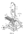
- FIGS. 1 a and 1b a device for crimping wires 5-1 to 5.4 of a multi-core, here four-wire, cable 5 is shown.
- the wires 5.1 to 5.4 are surrounded by a shield not shown in the figures and outside of an insulating sheath 5.5 enclosed.
- the cable 5 is stripped at one end, so that there are exposed the wires 5.1 to 5.4 for processing.
- the device comprises as a first tool a crimper 1, which cooperates with a second tool, here referred to as anvil 2. Furthermore, in the presented embodiment, the device also comprises a so-called cutter 3 for separating crimp contacts 6.1, which have Crimplaschen 6.11, from a carrier strip 6 of a band product.
- a so-called cutter 3 for separating crimp contacts 6.1, which have Crimplaschen 6.11, from a carrier strip 6 of a band product.
- x, y, z space coordinate directions for explaining the relative orientation of device components are shown.
- the cutter 3 is therefore mounted in the y-direction offset from the anvil 2 on a support 4.
- the anvil 2 is designed in two parts and thus comprises two anvil parts 2.1, 2.2.
- the anvil parts 2.1, 2.2 also rest on the support 4, which comprises two force sensors 4.1, 4.2.
- the stamp 1.1, 1.2 are arranged in the assembled state so that the indentations are 1.11, 1.21 offset from each other in the x direction.
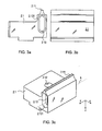
- the first anvil part 2.1 is shown in detail.
- the other anvil part 2.2 differs from the first anvil part 2.1 only by a mirror-image geometry and is in the 3d figure shown.
- the anvil parts 2.1, 2.2 also each have a recess 2.11, 2.21 and can be fastened to the support 4 with the aid of bores 2.12, 2.22.
- each of the anvil parts 2.1, 2.2 each have a recess 2.13, 2.23, which is in each case provided with a circumferential chamfer 2.131, 2.231.
- the recesses are 2.13, 2.23 designed as slots, which completely penetrate the respective anvil part 2.1, 2.2 in the y-direction.
- the recesses 2.13, 2.23 are here also symmetrically below, so symmetrically offset in the z direction, with respect to the respective indentation 2.11, 2.21 arranged.
- the cutter 3 has according to the FIGS. 1a and 4 an opening 3.3, in which the wires 5.1 to 5.4 of the cable 5 can be inserted in the y-direction. Furthermore, the cutter 3 comprises a first wedge-shaped guide element 3.1 and a second wedge-shaped guide element 3.2, wherein the two guide elements 3.1, 3.2 are arranged orthogonal to each other or oriented. Through a gap 3.4, the carrier strip 6, on which the crimp contacts are lined up 6.1, are performed. The gap 3.4 penetrates here the cutter 3 also in the region of the first guide element 3.1.
- the crimper 1 and the anvil 2 each have two indentations 1.11, 2.11; 1.21, 2.21 which, according to the FIG. 1a be penetrated by virtual lines g.
- the straight lines g are oriented in the y-direction and the two indentations 1.11, 2.11; 1.21, 2.21 each offset in the x-direction to each other.
- the anvil parts 2.1, 2.2 of geometric straight lines h which are oriented in ay direction, can be penetrated through the recesses 2.13, 2.23.
- the geometric straight lines h also penetrate the cutter 3 in the region of the opening 3.3 (FIG. FIG. 4 ).
- the guide elements 3.1, 3.2 Due to the geometric design of the guide elements 3.1, 3.2, in particular by the selected wedge angle, a very exact position with respect to the immersion depth in the y direction can be achieved for the relevant cable 5.
- the guide elements 3.1, 3.2 at the same time constitute an axial stop for the cable 5.
- the relevant shroud length here can be only 7.5 mm.
- the respective crimp contacts 6.1 are separated from the carrier strip 6 by a stroke movement of the cutter 3 running in the z-direction. The separation takes place by a shearing between an edge of the slot 3.4 and edges of the anvil parts 2.1, 2.2. The crimper 1 is then again moved counter to the z-direction of the wires 5.1, 5.2.
- the cable 5 is pulled out in the y-direction from the anvil 2 and the cutter 3 and rotated 180 ° about its longitudinal axis (or about the y-axis). Thereafter, the cable 5 is moved back to the cutter 3, so that the wires 5.1 to 5.4 are again passed through the cutter 3 therethrough. Now the ends of the wires 5.1 to 5.4 with the help of the guide elements 3.1, 3.2 directed into the corresponding positions, so that then the already crimped wires 5.1, 5.2 are pushed into the recess 2.13, 2.23 of the first anvil part 2.1 and the second anvil part 2.2. The other two wires 5.3, 5.4 are then treated analogously to the crimping process described above. The crimping of the wires 5.1 to 5.4 can be carried out fully automatically by the device described in the first embodiment.
- a cutter 3a (FIG. FIGS. 5a-5c ), otherwise the other device components are configured as in the first embodiment.
- the cutter 3a is characterized in particular in that it has a special geometry of the opening 3.3a.
- the opening 3.3a is bounded by a substantially hollow cylindrical wall, which is open towards the crimper 1 in the z direction.
- This particular embodiment of the cutter 3a is particularly advantageous when a semi-automatic crimping takes place, ie when the 180 ° rotation of the cable 5 between the two crimping operations is performed by hand.
- the substantially hollow cylindrical wall the cable 5 is enclosed, so that a radial guidance of the cable 5 is made possible.
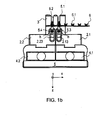
- the third embodiment according to the FIGS. 6a to 6e also has a crimper 1b with a first punch 1.1b and a second punch 1.2b.
- the two punches 1.1b, 1.2b each have a recess 1.11b, 1.21b for receiving a pair of wires 5.1 to 5.4.
- the two punches 1.1, 1.2 can be connected to each other in the z-direction adjustable, as in the first embodiment.
- the stamp 1.1 b, 1.2 b are arranged in the assembled state so that the indentations are 1.11, 1.21 offset in the x direction to each other.
- each stamp 1.1 b, 1.2 b each have a recess 1.13, 1.23, which is provided in each case with a peripheral chamfer 1.131, 1.232.
- the recesses are 1.13, 1.23 designed as slots, which the respective stamp 1.1 b, 1.2b in the y direction completely penetrate.
- the recesses 1.13, 1.23 are here also symmetrically above, so offset symmetrically against the z-direction, with respect to the respective indentation 1.11b. 1.21b arranged.
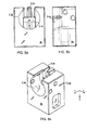
- the anvil 2b consists of two anvil parts 2.1b, 2.2b.
- the third embodiment is in the FIG. 6d only one anvil part 2.1b shown.
- the other anvil part 2.2b of the third embodiment is not shown in detail, especially since this differs from the first anvil part 2.1b only by a mirror-image geometry.
- the anvil part 2.1b also has a recess 2.11b and can be attached to the support 4 by means of a bore 2.12b.
- those of the third embodiment no recesses 2.11, 2.21.
- the four wires 5.1 to 5.4 of the cable 5 are to be crimped, then this is also done with the arrangement according to the third embodiment in two stages. For example, first the cores 5.3 and 5.4 are crimped and subsequently the wires 5.1 and 5.2. In the course of such processing, the wires 5.1 to 5.4 are guided by the guide elements 3.1b, 3.2b so that the first not to be crimped wires 5.1, 5.2 are directed against the z-direction, so that the ends of the respective wires 5.1, 5.2 immerse in the recesses 1.13, 1.23 of the stamp 1.1b, 1.2b.
- the recesses 1.13, 1.23 are dimensioned with respect to their extension in the z-direction so that even in the rest position of the two punches 1.1 b, 1.2b the ends of the first not to be crimped wires 5.1, 5.2 in the recesses 1.13, 1.23 are inserted.
- FIG. 6a Fig. 3 shows the crimping apparatus in which the crimper 1b has been moved to a processing position relative to the anvil 2b in the z-direction.
- the wires 5.3, 5.4 are then crimped as in the first embodiment. Thereafter, the cable 5 is first pulled out of the device in the y direction and then a 180 ° rotation of the cable 5 is made before it is pushed back into the device for crimping the remaining wires 5.1, 5.2.
- a crimping apparatus according to the FIGS. 7a to 7c shown, which is particularly suitable for crimping two-wire cables. Accordingly, here is a one-piece 1.1c crimper used with a dent 1.11c.
- the cutter 3c comprises according to the FIGS. 7a and 7b an opening 3.3c and only a wedge-shaped guide element 3.1c and a slot 3.4c to guide the carrier strip.
- the anvil 2.1c is designed here in one piece and has a recess 2.11c and a recess 2.13c.
- the two-wire cable is now inserted into the crimping device according to the fourth embodiment, that a vein between the indentations 1.11c, 2.11c of the crimper 1.1c and the anvil 2.1c comes to rest, while the second wire in the opening of the 3.3c Cutter 3c and in the recess 2.13c of the anvil 2.1c is introduced.
- the cable is rotated 180 ° and the second wire is crimped accordingly.
- FIGS. 8a and 8b is a device for stripping wires 5.1 to 5.4 of a multi-core cable 5 shown according to a fifth embodiment of the invention.
- the device comprises as the first tool a first knife 10, which cooperates with a second tool, referred to here as the second knife 20.
- the first knife 10 and the second knife 20 are designed in one piece and comprise according to the FIG. 8c in each case two indentations 10.21, 10.22, 20.21, 20.22 arranged offset from one another in the x-direction.
- the knives 10, 20 each have a pair of recesses 10.13, 20.13.
- the recesses 10.13, 20.13 are designed as rounded rectangles, which completely penetrate the respective blades 10, 20 in the y-direction.
- the recesses 10.13, 20.13 are here also symmetrically below and above, so in each case symmetrically offset in the z-direction, with respect to the respective recess 20.11, 20.21 both knives 10, 20 are arranged.
- the knives 10, 20 are connected with jaws 11, 21 which are movable relative to one another in the z-direction.
- the four wires 5.1 to 5.4 of the cable 5 to be stripped this is done in two stages. For example, first the wires 5.1 and 5.2 are stripped and then the wires 5.3 and 5.4. In the course of such processing, the cable 5 is opposite to the y-direction (in the FIG. 8b Coming from the right) placed so that the first not be stripped wires 5.3, 5.4 dip into the recesses 10.13 of the first knife 10.
- the recesses 10.13 are dimensioned with respect to their extent in the z-direction so that even in the rest position of the blades 10, 20, the ends of the first not be stripped wires 5.3, 5.4 are inserted into the recesses 10.13.
- the knives 10, 20 again moved slightly away from the wires 5.1, 5.2 in the z-direction, so that the knives 10, 20 still remain within the insulation of the wires 5.1, 5.2.
- the movable jaws 11, 21 are then moved counter to the y direction ( Figures 8a, 8b ) shifted, so that the trimmed Isoll fürsenden be deducted.
- knives 10, 20 are further moved apart in the z-direction.
- the movable jaws 11, 21 are finally against the z-direction (in the FIG. 8b moved upward) so that the openings between the recesses 10.21, 10.22, 20.21, 20.22 are at the same height as the wires 5.3. 5.4, which were not stripped in the first step.
- the invention also includes the combination of individual elements of the various embodiments.
- a crimping of the four wires 5.1 to 5.4 can be carried out using the devices according to the third and the first embodiment sequentially.
- the arrangement according to the FIG. 6a as a crimping station and the one according to the FIG. 1a be seen as another crimping station within a comprehensive apparatus for crimping a multi-core cable 5.
- the crimping station first in a first phase with the crimping station according to the FIG.
- FIG. 6a a position of the punch 1b is shown, as it is present during crimping, ie in the crimping or processing position. In this case, of course, in the processing position, the number of lines g, by the indentations 1.11b, 2.11b; 1.21b, 2.21b are going to be reduced to two.
- the cable 5 with the crimped wires 5.3, 5.4 by means of a transfer unit of the other crimping station according to the first embodiment, as in FIG. 1a shown supplied without rotation of the cable 5 is made about the y-axis.
- the upper wires 5.1, 5.2 are crimped, while the already crimped wires 5.3, 5.4 dip into the recesses 2.13, 2.23 of the anvil parts 2.1, 2.2.
- a cable assembly with two different crimping lugs 6. 1 can be made in a simple manner.
- an outer pair of wires 5.1, 5.2 are equipped with two longer Crimplaschen 6.1, whereas then on an inner pair of wires 5.3, 5.4 shorter Crimplaschen 6.2 can be attached.
Claims (15)
- Dispositif de sertissage ou de dénudement d'un conducteur (5.1, 5.2) d'un câble (5) à plusieurs conducteurs, comprenant un premier outil (1, 1b, 10) et un deuxième outil (2, 2b, 20), le premier outil (1, 1b, 10), pour le sertissage ou le dénudement des conducteurs (5.1, 5.2), pouvant être déplacé dans une direction z par rapport au deuxième outil (2, 2b, 20) dans une position d'usinage, caractérisé en ce que le dispositif est configuré de telle sorte que celui-ci présente un espace libre (1.13, 1.23 ; 2.13, 2.23 ; 2.13c ; 10.13, 20.13) dans lequel, dans la position d'usinage, un conducteur supplémentaire (5.3, 5.4) peut être reçu, et lequel est disposé de manière décalée dans la direction z par rapport au premier conducteur (5.1, 5.2).
- Dispositif selon la revendication 1, dans lequel l'espace libre (2.13, 2.23 ; 2.13c ; 20.13) est configuré sous forme d'un évidement dans le deuxième outil (2, 20).
- Dispositif selon la revendication 1 ou 2, dans lequel l'espace libre (1.13, 1.23 ; 10.13) est configuré sous forme d'un évidement dans le premier outil (1b, 10).
- Dispositif selon l'une quelconque des revendications précédentes, dans lequel, pour le sertissage ou le dénudement simultané de deux conducteurs (5.1, 5.2) du câble (5) à plusieurs conducteurs, le premier outil (1, 1b, 10) et/ou le deuxième outil (2, 2b, 20) présentent deux renfoncements (1.11, 1.21 ; 1.11b, 1.21b ; 10.21, 10.22 ; 2.11, 2.21 ; 2.11b ; 20.21, 20.22) de telle sorte que l'outil concerné (1, 1b ; 2, 2b ; 10, 20) puisse être traversé par des droites (g) qui sont orientées dans une direction y, à travers ces renfoncements (1.11, 1.21 ; 1.11b, 1.21b ; 10.21, 10.22 ; 2.11, 2.21 ; 2.11b ; 20.21, 20.22), les deux renfoncements (1.11, 1.21 ; 1.11b, 1.21b ; 10.21, 10.22 ; 2.11, 2.21 ; 2.11b ; 20.21, 20.22) étant disposés de manière décalée l'un par rapport à l'autre dans une direction x, la direction x étant orientée avec une composante directionnelle perpendiculaire aux directions y et z.
- Dispositif selon l'une quelconque des revendications 2 à 4, dans lequel, pour recevoir simultanément deux conducteurs (5.1, 5.2) du câble (5) à plusieurs conducteurs, le premier outil (1, 1b, 10) ou le deuxième outil (2, 2b, 20) présente deux espaces libres (1.13, 1.23 ; 2.13, 2.23 ; 2.13c ; 10.13, 20.13) configurés sous forme d'évidements, de telle sorte que l'outil concerné (1, 1b, 10 ; 2, 2b, 20) puisse être traversé par des droites (h), qui sont orientées dans une direction y, à travers ces espaces libres (1.13, 1.23 ; 2.13, 2.23 ; 2.13c ; 10.13, 20.13), les deux espaces libres (1.13, 1.23 ; 2.13, 2.23 ; 2.13c ; 10.13, 20.13) étant disposés de manière décalée l'un par rapport à l'autre dans une direction x, la direction x étant orientée avec une composante directionnelle perpendiculaire aux directions y et z.
- Dispositif selon l'une quelconque des revendications précédentes, dans lequel le dispositif présente un élément de guidage (3.1, 3.2 ; 3.1a, 3.2a ; 3.1b, 3.2b ; 3.1c) pour guider le conducteur respectif (5.1 à 5.4) dans une position prédéfinie.
- Dispositif selon l'une quelconque des revendications précédentes, dans lequel le dispositif présente deux éléments de guidage (3.1, 3.2 ; 3.1a, 3.2a ; 3.1b, 3.2b) pour guider le conducteur respectif (5.1 à 5.4) dans une position prédéfinie, le premier élément de guidage (3.1 ; 3.1a ; 3.1b) étant orienté avec une composante directionnelle perpendiculaire par rapport au deuxième élément de guidage (3.2 ; 3.2a ; 3.2b).
- Dispositif selon l'une quelconque des revendications 6 ou 7, dans lequel l'élément de guidage (3.1, 3.2 ; 3.1a, 3.2a ; 3.1b, 3.2b ; 3.1c) est configuré en forme de clavette pour guider le conducteur respectif (5.1 à 5.4) dans une position prédéfinie.
- Dispositif selon l'une quelconque des revendications 6 à 8, dans lequel le dispositif est prévu pour sertir les conducteurs (5.1 à 5.4) et l'un des éléments de guidage (3.1 ; 3.1a ; 3.1b ; 3.1c) présente une fente (3.4 ; 3.4a ; 3.4b ; 3.4c) pour recevoir une bande de support (6).
- Dispositif selon l'une quelconque des revendications précédentes, dans lequel le dispositif est prévu pour sertir les conducteurs (5.1 à 5.4) et le deuxième outil (2, 2b) comprend deux parties (2.1, 2.2 ; 2.1b, 2.2b) qui sont disposées de manière déplaçable l'une par rapport à l'autre dans la direction z et qui reposent sur un capteur de force respectif (4.1, 4.2).
- Dispositif selon l'une quelconque des revendications précédentes, dans lequel le dispositif est prévu pour sertir les conducteurs (5.1 à 5.4) et l'espace libre (2.13, 2.23 ; 2.13c ; 20.13) est configuré sous forme d'évidement dans le deuxième outil (2, 20) et présente un dispositif de coupe (3, 3a, 3b, 3c) qui comprend une ouverture (3.3, 3.3a, 3.3b, 3.3c), et le dispositif de coupe (3, 3a, 3b, 3c) est disposé par rapport au deuxième outil (2) de telle sorte que l'espace libre (2.13, 2.23 ; 2.13c) configuré sous forme d'évidement et l'ouverture (3.3, 3.3a, 3.3b, 3.3c) puissent être traversés par une droite (h) qui est orientée dans une direction y.
- Dispositif selon la revendication 11, dans lequel le dispositif de coupe (3, 3a, 3b, 3c) présente un élément de guidage (3.1, 3.2 ; 3.1a, 3.2a ; 3.1b, 3.2b ; 3.1c) pour guider le conducteur respectif (5.1 à 5.4) dans une position prédéfinie.
- Dispositif selon la revendication 11 ou 12, dans lequel un conducteur (5.1 à 5.4) peut être guidé par travers l'élément de guidage (3.1, 3.2 ; 3.1a, 3.2a ; 3.1b, 3.2b ; 3.1c) dans un espace libre (2.13, 2.23 ; 2.13c) configuré sous forme d'évidement et un autre conducteur (5.1 à 5.4) peut être guidé dans le renfoncement (2.11, 2.21 ; 2.11b) du deuxième outil (2).
- Dispositif selon la revendication 11, 12 ou 13, dans lequel le deuxième outil (2) présente- deux espaces libres (2.13, 2.23) configurés sous forme d'évidements et- deux renfoncements (2.11, 2.21 ; 2.11b), etle dispositif de coupe (3, 3a, 3b, 3c) présente deux éléments de guidage (3.1, 3.2 ; 3.1a, 3.2a ; 3.1b, 3.2b) pour guider un conducteur (5.1 à 5.4) dans les espaces libres (2.13, 2.23) et pour guider un autre conducteur dans les renfoncements (2.11, 2.21 ; 2.11b) du deuxième outil (2), le premier élément de guidage (3.1 ; 3.1a ; 3.1b) étant orienté avec une composante directionnelle perpendiculaire par rapport au deuxième élément de guidage (3.2 ; 3.2a ; 3.2b).
- Dispositif selon l'une quelconque des revendications précédentes, dans lequel le dispositif est prévu pour sertir le premier conducteur et le conducteur supplémentaire (5.1 à 5.4) et comprend deux postes de sertissage, chacun des postes de sertissage présentant un premier outil (1, 1b) et un deuxième outil (2, 2b) et pour le sertissage de l'un des conducteurs (5.1, 5.2, 5.3, 5.4), le premier outil respectif (1, 1b) pouvant être déplacé dans une position d'usinage dans la direction z par rapport au deuxième outil respectif (2, 2b), et- l'un des postes de sertissage est configuré pour sertir le premier conducteur (5.1, 5.2) de telle sorte que celui-ci présente un espace libre (2.13, 2.23 ; 2.13c) qui est configuré en tant qu'évidement dans le deuxième outil (2), dans lequel peut être reçu le conducteur supplémentaire (5.3, 5.4) dans la position d'usinage, et qui est disposé dans la direction z de manière décalée par rapport au premier conducteur (5.1, 5.2),- l'autre poste de sertissage est configuré pour sertir le conducteur supplémentaire (5.3, 5.4) de telle sorte que celui-ci présente un espace libre (1.13, 1.23) qui est configuré sous forme d'évidement dans le premier outil (1b), dans lequel peut être reçu le premier conducteur (5.1, 5.2) dans la position d'usinage, et qui est disposé dans la direction z de manière décalée par rapport au conducteur supplémentaire (5.3, 5.4).
Applications Claiming Priority (1)
| Application Number | Priority Date | Filing Date | Title |
|---|---|---|---|
| DE200810058168 DE102008058168A1 (de) | 2008-11-20 | 2008-11-20 | Vorrichtung zum Crimpen oder Abisolieren einer Ader eines mehradrigen Kabels |
Publications (3)
| Publication Number | Publication Date |
|---|---|
| EP2190080A2 EP2190080A2 (fr) | 2010-05-26 |
| EP2190080A3 EP2190080A3 (fr) | 2011-05-18 |
| EP2190080B1 true EP2190080B1 (fr) | 2013-11-06 |
Family
ID=41490551
Family Applications (1)
| Application Number | Title | Priority Date | Filing Date |
|---|---|---|---|
| EP20090014334 Active EP2190080B1 (fr) | 2008-11-20 | 2009-11-17 | Dispositif de sertissage et de dénudement d'un conducteur d'un câble à plusieurs fils |
Country Status (2)
| Country | Link |
|---|---|
| EP (1) | EP2190080B1 (fr) |
| DE (1) | DE102008058168A1 (fr) |
Cited By (3)
| Publication number | Priority date | Publication date | Assignee | Title |
|---|---|---|---|---|
| DE202017003670U1 (de) | 2017-07-13 | 2017-08-04 | Md Elektronik Gmbh | Vorrichtung zum Crimpen einer Ader eines Kabels |
| CN110024234A (zh) * | 2016-11-29 | 2019-07-16 | 住友电装株式会社 | 绞合电线固定用夹具及端子压接装置 |
| DE102019109174A1 (de) * | 2019-04-08 | 2020-10-08 | Murrplastik Produktionstechnik Gmbh | Vorrichtung zum Freilegen der Litzen eines elektrischen Kabels |
Families Citing this family (5)
| Publication number | Priority date | Publication date | Assignee | Title |
|---|---|---|---|---|
| CN103730806A (zh) * | 2012-10-10 | 2014-04-16 | 住友电气工业株式会社 | 电线的压接端子安装方法 |
| DE102013018834B4 (de) * | 2013-11-08 | 2019-03-21 | Komax SLE GmbH & Co. KG | Abisoliervorrichtung und -Verfahren |
| EP3309915B1 (fr) | 2016-10-14 | 2019-11-13 | Wezag GmbH Werkzeugfabrik | Pince à dénuder, couteau à dénuder, et procédé de dénudage |
| DE202021105479U1 (de) | 2021-10-11 | 2021-11-05 | Md Elektronik Gmbh | Abschneider |
| DE102022115017A1 (de) * | 2022-06-15 | 2023-12-21 | Md Elektronik Gmbh | Crimpwerkzeug |
Family Cites Families (5)
| Publication number | Priority date | Publication date | Assignee | Title |
|---|---|---|---|---|
| US4183383A (en) * | 1978-09-25 | 1980-01-15 | Artos Engineering Company | Wire shaping mechanism for production of wire leads |
| US4796358A (en) * | 1986-09-10 | 1989-01-10 | Amp Incorporated | Method and apparatus for assembly of electrical cable |
| CH693550A5 (de) | 1997-06-30 | 2003-09-30 | Komax Holding Ag | Krimpvorrichtung und Verfahren zu deren Betrieb. |
| ITVI20010114A1 (it) | 2001-05-15 | 2002-11-15 | Samec Divisione Costruzione Ma | Metodo per la troncatura e la sguainatura di cavi elettrici e macchina troncatrice-sguainatrice atta a realizzare tale metodo |
| CN100470932C (zh) * | 2004-04-23 | 2009-03-18 | 安普泰科电子西班牙股份有限公司 | 模块化电信连接插口和终端组件 |
-
2008
- 2008-11-20 DE DE200810058168 patent/DE102008058168A1/de not_active Withdrawn
-
2009
- 2009-11-17 EP EP20090014334 patent/EP2190080B1/fr active Active
Cited By (4)
| Publication number | Priority date | Publication date | Assignee | Title |
|---|---|---|---|---|
| CN110024234A (zh) * | 2016-11-29 | 2019-07-16 | 住友电装株式会社 | 绞合电线固定用夹具及端子压接装置 |
| CN110024234B (zh) * | 2016-11-29 | 2021-05-07 | 住友电装株式会社 | 绞合电线固定用夹具及端子压接装置 |
| DE202017003670U1 (de) | 2017-07-13 | 2017-08-04 | Md Elektronik Gmbh | Vorrichtung zum Crimpen einer Ader eines Kabels |
| DE102019109174A1 (de) * | 2019-04-08 | 2020-10-08 | Murrplastik Produktionstechnik Gmbh | Vorrichtung zum Freilegen der Litzen eines elektrischen Kabels |
Also Published As
| Publication number | Publication date |
|---|---|
| DE102008058168A1 (de) | 2010-05-27 |
| EP2190080A3 (fr) | 2011-05-18 |
| EP2190080A2 (fr) | 2010-05-26 |
Similar Documents
| Publication | Publication Date | Title |
|---|---|---|
| EP2190080B1 (fr) | Dispositif de sertissage et de dénudement d'un conducteur d'un câble à plusieurs fils | |
| DE69926701T2 (de) | Verarbeitungsverfahren und -apparat eines Kabelendes | |
| EP2871737B1 (fr) | Dispositif et procédé de dénudage | |
| EP2365586B1 (fr) | Connecteur à fiches câblé, notamment connecteur à fiches câblé multipolaire | |
| DE2361442A1 (de) | Elektrische kupplung und verfahren zur kontaktherstellung | |
| EP2144331A1 (fr) | Contact à déplacement d'isolation et dispositif de connexion | |
| EP2780993B1 (fr) | Détection d'une entaille sur un toron | |
| EP2919340A1 (fr) | Procédé de détermination de paramètres de dénudage pour dénuder un câble | |
| EP3161907A1 (fr) | Élément de connexion de câble | |
| EP3804048B1 (fr) | Dispositif et procédé servant à usiner une extrémité d'un câble électrique | |
| EP3057184A1 (fr) | Procédé et dispositif de fabrication d'un câble ainsi qu'un câble fabriqué selon ledit procédé | |
| DE4117915C2 (de) | Verfahren zum Entfernen des Mantels eines elektrischen Drahtes in einem Zwischenbereich | |
| DE202017003670U1 (de) | Vorrichtung zum Crimpen einer Ader eines Kabels | |
| EP4164073A1 (fr) | Dispositif de coupe | |
| DE102021108215B3 (de) | Verfahren und Vorrichtung zum Bearbeiten eines Kabels | |
| DE1152457B (de) | Vorrichtung zum Abmanteln und Einhaengen eines Kabeldrahtes in ein Anschlussstueck | |
| EP3236544B1 (fr) | Procédé de regroupement de conduites individuelles d'un faisceau de câbles | |
| DE3926782C1 (en) | Cutting cable to length and stripping - sliding clamp in closed position along predetermined path after cutting cable sleeve or cutting through cable | |
| EP2748895B1 (fr) | Dispositif de sertissage | |
| EP3520179B1 (fr) | Dispositif, procédé et système de sertissage inverse | |
| DE4325356C1 (de) | Vorrichtung zum Befestigen von Klemmkontakten an elektrische Leiter | |
| DE4027772A1 (de) | Verfahren zum kontaktieren der einzelnen leiter eines mehrleiterkabels und fuer das verfahren eingerichtete kontaktelemente | |
| EP3713023A1 (fr) | Dispositif ainsi que procédé d'isolation | |
| EP3799212A1 (fr) | Terminal de connexion | |
| DE102009040646B3 (de) | Vorrichtung zum Abtrennen eines Brückensteges eines Steckbrückensystems |
Legal Events
| Date | Code | Title | Description |
|---|---|---|---|
| PUAI | Public reference made under article 153(3) epc to a published international application that has entered the european phase |
Free format text: ORIGINAL CODE: 0009012 |
|
| AK | Designated contracting states |
Kind code of ref document: A2 Designated state(s): AT BE BG CH CY CZ DE DK EE ES FI FR GB GR HR HU IE IS IT LI LT LU LV MC MK MT NL NO PL PT RO SE SI SK SM TR |
|
| AX | Request for extension of the european patent |
Extension state: AL BA RS |
|
| PUAL | Search report despatched |
Free format text: ORIGINAL CODE: 0009013 |
|
| AK | Designated contracting states |
Kind code of ref document: A3 Designated state(s): AT BE BG CH CY CZ DE DK EE ES FI FR GB GR HR HU IE IS IT LI LT LU LV MC MK MT NL NO PL PT RO SE SI SK SM TR |
|
| AX | Request for extension of the european patent |
Extension state: AL BA RS |
|
| RIC1 | Information provided on ipc code assigned before grant |
Ipc: H01R 107/00 20060101ALI20110413BHEP Ipc: H02G 1/12 20060101ALI20110413BHEP Ipc: H01R 43/048 20060101AFI20100118BHEP |
|
| 17P | Request for examination filed |
Effective date: 20110419 |
|
| GRAP | Despatch of communication of intention to grant a patent |
Free format text: ORIGINAL CODE: EPIDOSNIGR1 |
|
| RIC1 | Information provided on ipc code assigned before grant |
Ipc: H01R 43/28 20060101ALN20130709BHEP Ipc: H01R 9/03 20060101ALN20130709BHEP Ipc: H01R 107/00 20060101ALI20130709BHEP Ipc: H01R 43/055 20060101ALN20130709BHEP Ipc: H02G 1/12 20060101ALI20130709BHEP Ipc: H01R 43/05 20060101ALN20130709BHEP Ipc: H01R 43/048 20060101AFI20130709BHEP |
|
| INTG | Intention to grant announced |
Effective date: 20130807 |
|
| GRAS | Grant fee paid |
Free format text: ORIGINAL CODE: EPIDOSNIGR3 |
|
| GRAA | (expected) grant |
Free format text: ORIGINAL CODE: 0009210 |
|
| AK | Designated contracting states |
Kind code of ref document: B1 Designated state(s): AT BE BG CH CY CZ DE DK EE ES FI FR GB GR HR HU IE IS IT LI LT LU LV MC MK MT NL NO PL PT RO SE SI SK SM TR |
|
| REG | Reference to a national code |
Ref country code: GB Ref legal event code: FG4D Free format text: NOT ENGLISH |
|
| REG | Reference to a national code |
Ref country code: CH Ref legal event code: NV Representative=s name: ICB INGENIEURS CONSEILS EN BREVETS SA, CH Ref country code: CH Ref legal event code: EP |
|
| REG | Reference to a national code |
Ref country code: AT Ref legal event code: REF Ref document number: 639987 Country of ref document: AT Kind code of ref document: T Effective date: 20131215 |
|
| REG | Reference to a national code |
Ref country code: IE Ref legal event code: FG4D Free format text: LANGUAGE OF EP DOCUMENT: GERMAN |
|
| REG | Reference to a national code |
Ref country code: DE Ref legal event code: R096 Ref document number: 502009008275 Country of ref document: DE Effective date: 20140102 |
|
| REG | Reference to a national code |
Ref country code: NL Ref legal event code: VDEP Effective date: 20131106 |
|
| REG | Reference to a national code |
Ref country code: LT Ref legal event code: MG4D |
|
| PG25 | Lapsed in a contracting state [announced via postgrant information from national office to epo] |
Ref country code: NO Free format text: LAPSE BECAUSE OF FAILURE TO SUBMIT A TRANSLATION OF THE DESCRIPTION OR TO PAY THE FEE WITHIN THE PRESCRIBED TIME-LIMIT Effective date: 20140206 Ref country code: NL Free format text: LAPSE BECAUSE OF FAILURE TO SUBMIT A TRANSLATION OF THE DESCRIPTION OR TO PAY THE FEE WITHIN THE PRESCRIBED TIME-LIMIT Effective date: 20131106 Ref country code: FI Free format text: LAPSE BECAUSE OF FAILURE TO SUBMIT A TRANSLATION OF THE DESCRIPTION OR TO PAY THE FEE WITHIN THE PRESCRIBED TIME-LIMIT Effective date: 20131106 Ref country code: IS Free format text: LAPSE BECAUSE OF FAILURE TO SUBMIT A TRANSLATION OF THE DESCRIPTION OR TO PAY THE FEE WITHIN THE PRESCRIBED TIME-LIMIT Effective date: 20140306 Ref country code: HR Free format text: LAPSE BECAUSE OF FAILURE TO SUBMIT A TRANSLATION OF THE DESCRIPTION OR TO PAY THE FEE WITHIN THE PRESCRIBED TIME-LIMIT Effective date: 20131106 Ref country code: LT Free format text: LAPSE BECAUSE OF FAILURE TO SUBMIT A TRANSLATION OF THE DESCRIPTION OR TO PAY THE FEE WITHIN THE PRESCRIBED TIME-LIMIT Effective date: 20131106 Ref country code: SE Free format text: LAPSE BECAUSE OF FAILURE TO SUBMIT A TRANSLATION OF THE DESCRIPTION OR TO PAY THE FEE WITHIN THE PRESCRIBED TIME-LIMIT Effective date: 20131106 |
|
| PG25 | Lapsed in a contracting state [announced via postgrant information from national office to epo] |
Ref country code: LV Free format text: LAPSE BECAUSE OF FAILURE TO SUBMIT A TRANSLATION OF THE DESCRIPTION OR TO PAY THE FEE WITHIN THE PRESCRIBED TIME-LIMIT Effective date: 20131106 Ref country code: ES Free format text: LAPSE BECAUSE OF FAILURE TO SUBMIT A TRANSLATION OF THE DESCRIPTION OR TO PAY THE FEE WITHIN THE PRESCRIBED TIME-LIMIT Effective date: 20131106 |
|
| BERE | Be: lapsed |
Owner name: MD ELEKTRONIK G.M.B.H. Effective date: 20131130 |
|
| PG25 | Lapsed in a contracting state [announced via postgrant information from national office to epo] |
Ref country code: PT Free format text: LAPSE BECAUSE OF FAILURE TO SUBMIT A TRANSLATION OF THE DESCRIPTION OR TO PAY THE FEE WITHIN THE PRESCRIBED TIME-LIMIT Effective date: 20140306 |
|
| PG25 | Lapsed in a contracting state [announced via postgrant information from national office to epo] |
Ref country code: EE Free format text: LAPSE BECAUSE OF FAILURE TO SUBMIT A TRANSLATION OF THE DESCRIPTION OR TO PAY THE FEE WITHIN THE PRESCRIBED TIME-LIMIT Effective date: 20131106 |
|
| REG | Reference to a national code |
Ref country code: DE Ref legal event code: R097 Ref document number: 502009008275 Country of ref document: DE |
|
| REG | Reference to a national code |
Ref country code: IE Ref legal event code: MM4A |
|
| PG25 | Lapsed in a contracting state [announced via postgrant information from national office to epo] |
Ref country code: CZ Free format text: LAPSE BECAUSE OF FAILURE TO SUBMIT A TRANSLATION OF THE DESCRIPTION OR TO PAY THE FEE WITHIN THE PRESCRIBED TIME-LIMIT Effective date: 20131106 Ref country code: MC Free format text: LAPSE BECAUSE OF FAILURE TO SUBMIT A TRANSLATION OF THE DESCRIPTION OR TO PAY THE FEE WITHIN THE PRESCRIBED TIME-LIMIT Effective date: 20131106 Ref country code: PL Free format text: LAPSE BECAUSE OF FAILURE TO SUBMIT A TRANSLATION OF THE DESCRIPTION OR TO PAY THE FEE WITHIN THE PRESCRIBED TIME-LIMIT Effective date: 20131106 Ref country code: SK Free format text: LAPSE BECAUSE OF FAILURE TO SUBMIT A TRANSLATION OF THE DESCRIPTION OR TO PAY THE FEE WITHIN THE PRESCRIBED TIME-LIMIT Effective date: 20131106 Ref country code: RO Free format text: LAPSE BECAUSE OF FAILURE TO SUBMIT A TRANSLATION OF THE DESCRIPTION OR TO PAY THE FEE WITHIN THE PRESCRIBED TIME-LIMIT Effective date: 20131106 |
|
| PLBE | No opposition filed within time limit |
Free format text: ORIGINAL CODE: 0009261 |
|
| STAA | Information on the status of an ep patent application or granted ep patent |
Free format text: STATUS: NO OPPOSITION FILED WITHIN TIME LIMIT |
|
| PG25 | Lapsed in a contracting state [announced via postgrant information from national office to epo] |
Ref country code: BE Free format text: LAPSE BECAUSE OF NON-PAYMENT OF DUE FEES Effective date: 20131130 Ref country code: DK Free format text: LAPSE BECAUSE OF FAILURE TO SUBMIT A TRANSLATION OF THE DESCRIPTION OR TO PAY THE FEE WITHIN THE PRESCRIBED TIME-LIMIT Effective date: 20131106 |
|
| 26N | No opposition filed |
Effective date: 20140807 |
|
| REG | Reference to a national code |
Ref country code: FR Ref legal event code: ST Effective date: 20140917 |
|
| GBPC | Gb: european patent ceased through non-payment of renewal fee |
Effective date: 20140206 |
|
| PG25 | Lapsed in a contracting state [announced via postgrant information from national office to epo] |
Ref country code: IE Free format text: LAPSE BECAUSE OF NON-PAYMENT OF DUE FEES Effective date: 20131117 |
|
| REG | Reference to a national code |
Ref country code: DE Ref legal event code: R097 Ref document number: 502009008275 Country of ref document: DE Effective date: 20140807 |
|
| PG25 | Lapsed in a contracting state [announced via postgrant information from national office to epo] |
Ref country code: FR Free format text: LAPSE BECAUSE OF NON-PAYMENT OF DUE FEES Effective date: 20140106 |
|
| PG25 | Lapsed in a contracting state [announced via postgrant information from national office to epo] |
Ref country code: GB Free format text: LAPSE BECAUSE OF NON-PAYMENT OF DUE FEES Effective date: 20140206 |
|
| PG25 | Lapsed in a contracting state [announced via postgrant information from national office to epo] |
Ref country code: SI Free format text: LAPSE BECAUSE OF FAILURE TO SUBMIT A TRANSLATION OF THE DESCRIPTION OR TO PAY THE FEE WITHIN THE PRESCRIBED TIME-LIMIT Effective date: 20131106 |
|
| PG25 | Lapsed in a contracting state [announced via postgrant information from national office to epo] |
Ref country code: SM Free format text: LAPSE BECAUSE OF FAILURE TO SUBMIT A TRANSLATION OF THE DESCRIPTION OR TO PAY THE FEE WITHIN THE PRESCRIBED TIME-LIMIT Effective date: 20131106 |
|
| PG25 | Lapsed in a contracting state [announced via postgrant information from national office to epo] |
Ref country code: CY Free format text: LAPSE BECAUSE OF FAILURE TO SUBMIT A TRANSLATION OF THE DESCRIPTION OR TO PAY THE FEE WITHIN THE PRESCRIBED TIME-LIMIT Effective date: 20131106 Ref country code: TR Free format text: LAPSE BECAUSE OF FAILURE TO SUBMIT A TRANSLATION OF THE DESCRIPTION OR TO PAY THE FEE WITHIN THE PRESCRIBED TIME-LIMIT Effective date: 20131106 |
|
| PG25 | Lapsed in a contracting state [announced via postgrant information from national office to epo] |
Ref country code: LU Free format text: LAPSE BECAUSE OF NON-PAYMENT OF DUE FEES Effective date: 20131117 Ref country code: MK Free format text: LAPSE BECAUSE OF FAILURE TO SUBMIT A TRANSLATION OF THE DESCRIPTION OR TO PAY THE FEE WITHIN THE PRESCRIBED TIME-LIMIT Effective date: 20131106 Ref country code: BG Free format text: LAPSE BECAUSE OF FAILURE TO SUBMIT A TRANSLATION OF THE DESCRIPTION OR TO PAY THE FEE WITHIN THE PRESCRIBED TIME-LIMIT Effective date: 20131106 Ref country code: HU Free format text: LAPSE BECAUSE OF FAILURE TO SUBMIT A TRANSLATION OF THE DESCRIPTION OR TO PAY THE FEE WITHIN THE PRESCRIBED TIME-LIMIT; INVALID AB INITIO Effective date: 20091117 |
|
| PG25 | Lapsed in a contracting state [announced via postgrant information from national office to epo] |
Ref country code: GR Free format text: LAPSE BECAUSE OF NON-PAYMENT OF DUE FEES Effective date: 20131106 Ref country code: MT Free format text: LAPSE BECAUSE OF FAILURE TO SUBMIT A TRANSLATION OF THE DESCRIPTION OR TO PAY THE FEE WITHIN THE PRESCRIBED TIME-LIMIT Effective date: 20131106 |
|
| REG | Reference to a national code |
Ref country code: AT Ref legal event code: MM01 Ref document number: 639987 Country of ref document: AT Kind code of ref document: T Effective date: 20141117 |
|
| PG25 | Lapsed in a contracting state [announced via postgrant information from national office to epo] |
Ref country code: AT Free format text: LAPSE BECAUSE OF NON-PAYMENT OF DUE FEES Effective date: 20141117 |
|
| PG25 | Lapsed in a contracting state [announced via postgrant information from national office to epo] |
Ref country code: GR Free format text: LAPSE BECAUSE OF FAILURE TO SUBMIT A TRANSLATION OF THE DESCRIPTION OR TO PAY THE FEE WITHIN THE PRESCRIBED TIME-LIMIT Effective date: 20140207 |
|
| REG | Reference to a national code |
Ref country code: DE Ref legal event code: R082 Ref document number: 502009008275 Country of ref document: DE |
|
| PGFP | Annual fee paid to national office [announced via postgrant information from national office to epo] |
Ref country code: IT Payment date: 20231124 Year of fee payment: 15 Ref country code: DE Payment date: 20231121 Year of fee payment: 15 Ref country code: CH Payment date: 20231201 Year of fee payment: 15 |