EP2187336B1 - Procédé de lecture d'images à motifs, appareil pour la lecture d'images à motifs, procédé de traitement d'informations et programme de lecture d'images à motifs - Google Patents
Procédé de lecture d'images à motifs, appareil pour la lecture d'images à motifs, procédé de traitement d'informations et programme de lecture d'images à motifs Download PDFInfo
- Publication number
- EP2187336B1 EP2187336B1 EP09252551.8A EP09252551A EP2187336B1 EP 2187336 B1 EP2187336 B1 EP 2187336B1 EP 09252551 A EP09252551 A EP 09252551A EP 2187336 B1 EP2187336 B1 EP 2187336B1
- Authority
- EP
- European Patent Office
- Prior art keywords
- page
- pattern image
- pages
- capturing
- image
- Prior art date
- Legal status (The legal status is an assumption and is not a legal conclusion. Google has not performed a legal analysis and makes no representation as to the accuracy of the status listed.)
- Not-in-force
Links
Images


Classifications
-
- G—PHYSICS
- G06—COMPUTING; CALCULATING OR COUNTING
- G06K—GRAPHICAL DATA READING; PRESENTATION OF DATA; RECORD CARRIERS; HANDLING RECORD CARRIERS
- G06K7/00—Methods or arrangements for sensing record carriers, e.g. for reading patterns
- G06K7/10—Methods or arrangements for sensing record carriers, e.g. for reading patterns by electromagnetic radiation, e.g. optical sensing; by corpuscular radiation
- G06K7/10544—Methods or arrangements for sensing record carriers, e.g. for reading patterns by electromagnetic radiation, e.g. optical sensing; by corpuscular radiation by scanning of the records by radiation in the optical part of the electromagnetic spectrum
- G06K7/10712—Fixed beam scanning
- G06K7/10722—Photodetector array or CCD scanning
-
- G—PHYSICS
- G06—COMPUTING; CALCULATING OR COUNTING
- G06K—GRAPHICAL DATA READING; PRESENTATION OF DATA; RECORD CARRIERS; HANDLING RECORD CARRIERS
- G06K19/00—Record carriers for use with machines and with at least a part designed to carry digital markings
- G06K19/06—Record carriers for use with machines and with at least a part designed to carry digital markings characterised by the kind of the digital marking, e.g. shape, nature, code
- G06K19/06009—Record carriers for use with machines and with at least a part designed to carry digital markings characterised by the kind of the digital marking, e.g. shape, nature, code with optically detectable marking
- G06K19/06037—Record carriers for use with machines and with at least a part designed to carry digital markings characterised by the kind of the digital marking, e.g. shape, nature, code with optically detectable marking multi-dimensional coding
-
- G—PHYSICS
- G06—COMPUTING; CALCULATING OR COUNTING
- G06K—GRAPHICAL DATA READING; PRESENTATION OF DATA; RECORD CARRIERS; HANDLING RECORD CARRIERS
- G06K7/00—Methods or arrangements for sensing record carriers, e.g. for reading patterns
- G06K7/10—Methods or arrangements for sensing record carriers, e.g. for reading patterns by electromagnetic radiation, e.g. optical sensing; by corpuscular radiation
- G06K7/10544—Methods or arrangements for sensing record carriers, e.g. for reading patterns by electromagnetic radiation, e.g. optical sensing; by corpuscular radiation by scanning of the records by radiation in the optical part of the electromagnetic spectrum
- G06K7/10821—Methods or arrangements for sensing record carriers, e.g. for reading patterns by electromagnetic radiation, e.g. optical sensing; by corpuscular radiation by scanning of the records by radiation in the optical part of the electromagnetic spectrum further details of bar or optical code scanning devices
- G06K7/1095—Methods or arrangements for sensing record carriers, e.g. for reading patterns by electromagnetic radiation, e.g. optical sensing; by corpuscular radiation by scanning of the records by radiation in the optical part of the electromagnetic spectrum further details of bar or optical code scanning devices the scanner comprising adaptations for scanning a record carrier that is displayed on a display-screen or the like
-
- G—PHYSICS
- G06—COMPUTING; CALCULATING OR COUNTING
- G06K—GRAPHICAL DATA READING; PRESENTATION OF DATA; RECORD CARRIERS; HANDLING RECORD CARRIERS
- G06K7/00—Methods or arrangements for sensing record carriers, e.g. for reading patterns
- G06K7/10—Methods or arrangements for sensing record carriers, e.g. for reading patterns by electromagnetic radiation, e.g. optical sensing; by corpuscular radiation
- G06K7/14—Methods or arrangements for sensing record carriers, e.g. for reading patterns by electromagnetic radiation, e.g. optical sensing; by corpuscular radiation using light without selection of wavelength, e.g. sensing reflected white light
- G06K7/1404—Methods for optical code recognition
- G06K7/1408—Methods for optical code recognition the method being specifically adapted for the type of code
- G06K7/1417—2D bar codes
Definitions
- the present invention relates to a method and apparatus for reading a pattern image, information processing method, and a program for reading a pattern image.
- Two-dimensional barcodes such as QR code® and the like, which are obtained by two-dimensionally expanding a one-dimensional barcode (bars are arranged in only one direction) also increasingly spread.
- the one-dimensional barcode can express around 20 alphanumeric characters.
- the standard regarding a two-dimensional barcode capable of storing information of more than 2000 characters has appeared.
- the barcodes are not all displayed on paper mediums.
- the pattern image of a barcode posted on a Web page may be displayed on a display screen and captured by the camera of the mobile phone terminal so as to acquire URL information.
- a communication apparatus such as a mobile phone terminal or the like
- the amount of information is limited due to the optical limitation.
- character information of not more than about 2000 characters can be presented. This is because, even though the recording density of the barcode patterns simply increases, the camera mounted in a communication apparatus, such as a mobile phone terminal or the like, has a limited resolution, so the amount of information to be imported is limited.
- a method of increasing the amount of information to be presented by a barcode is described in Japanese Patent Application Publication No. 2007-156969 .
- the barcode presentation method described in Japanese Patent Application Publication No. 2007-156969 is applied to the pattern image of a barcode displayed on a display screen.
- the pattern image of the barcode is not displayed in the form of a still image, but the pattern image of the barcode is configured such that multiple sheets (multiple pages) are displayed and presented successively in a temporal direction, like a motion image.
- information can be presented by a barcode pattern group having multiple pages and therefore a large amount of information can be presented.
- the pattern image of a barcode having multiple pages is captured and read by the camera, it is preferable that the multiple pages are read rapidly in a short time. That is, it is important to rapidly photograph and import each of the multiple pages and to decode barcode information.
- each page is captured more than once and multiple sheets are stored.
- the sheets to which the same synchronization information is added are grouped to be determined as the same page and thus each page is acquired.
- a buffer memory should have a large capacity.
- US2007023523 discloses an image generator which generates a code pattern image by mutually arranging several position-dependent code images including position-dependent information differing for every position, at predetermined spacing along one side.
- the pattern image consists of repeated arrangement of position-independent code image including position-independent information in common at various positions, in the spacing between position-dependent code images.
- JP2007156969 describes an information transfer system for sending information by a two-dimensional code such as a quick response (QR) code using a video signal.
- An image analysis unit obtains information by selecting and analyzing code information by predetermined space.
- JP2005182629 discloses an information transmission and reception system wherein a personal computer stores actual situation codes and frame order codes in left and right side blocks of frame.
- a display device displays the codes stored in right side blocks at predetermined frame rate.
- a camera of a cell phone photographs the displayed codes.
- a recognition unit recognizes the actual situation frame in left side blocks when frame order codes are continuing, based on the photographed image.
- JP2004078351 discloses an internet-based bar-code production apparatus.
- the input bar-code information are recorded and converted into still-picture bar-codes by a still-picture bar-code generation unit.
- a moving-image bar-code generation unit combines the still-picture bar-codes displayed on a screen, sequentially for generating the moving-image bar-code which changes in time.
- the pattern image maybe configured such that each page includes the relevant page information indicating the position of the relevant page.
- the page interval between the read two pages that is, how many pages are placed between the read two pages can be detected from the relevant page information of each of the two pages of the pattern image. Therefore, if the capturing time interval between the two pages of the pattern image is divided by the detected page interval, the provision time interval for one page is determined.
- each page is captured and imported with the calculated capturing timing.
- all pages of the pattern image can be captured and imported for at least two cycles of the cyclic provision period of the pattern image having the multiple pages at a minimum so as to read the pattern image.
- the pages of the pattern image are sequentially read, so the capacity of the buffer memory is reduced, as compared with a case where each page is captured multiple times and the captured sheets are grouped.
- the memory capacity may correspond to the number of pages.
- the pattern image is the pattern image of a two-dimensional barcode having a QR code (Registered Trademark).
- Fig. 2 shows an example of the configuration of an information processing system to which a method of reading a code image according to an embodiment of the invention is applied.
- the information processing system of Fig. 2 includes an image display device 1, and a mobile phone terminal 2 having a camera serving as a capturing section.
- the image display device 1 provides advertising image information, and also displays information associated with the advertising on a display screen 11 as the pattern image 12 of a two-dimensional barcode having one or multiple pages (hereinafter, the pattern image of the two-dimensional barcode is referred to as a two-dimensional barcode image).
- the two-dimensional barcode image provides, for example, information including information regarding the location associated with advertising, provision time information, provision location information, the URL of a home page on which associated information is provided, provision source information, and the like.
- the two-dimensional barcode image is a pattern image including multiple pages.
- the pattern image of each page of the two-dimensional barcode image of this embodiment includes, as page index information, total page count information indicating the total number of pages (also referred to as total page count), and relevant page information indicating the page number of each page.
- page index information e.g., page index information
- total page count information indicating the total number of pages
- relevant page information indicating the page number of each page.
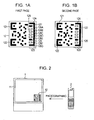
- FIG. 1A and 1B a pattern image including multiple pages.
- the two-dimensional barcode image 12 of this example includes auxiliary patterns 121 and 122 at the upper and lower left corners, similarly to the pattern image of the typical two-dimensional barcode, and a page index pattern 123 at the right lateral portion.
- the page index pattern 123 is an example of page index information.
- a pattern obtained by converting code information is drawn in a space excluding the auxiliary patterns 121 and 122 and the page index pattern 123.
- the page index pattern 123 has a U-shaped pattern 124, and a total page count bar 126 and a relevant page display bar 127 which are provided in a space 125 between the upper and lower bars of the U-shaped pattern 124.
- the total page count bar 126 and the relevant page display bar 127 are displayed as black lateral bars.
- the U-shaped pattern 124 also serves as an auxiliary pattern which indicates the positions of the upper and lower right corners.
- the position of the total page count bar 126 in the space 125 between the upper and lower bars of the U-shaped pattern 124 is changed depending on the total number of pages in the two-dimensional barcode image 12.
- the position of the relevant page display bar 127 in the space 125 between the upper and lower bars of the U-shaped pattern 124 is changed depending on the position of the relevant page in the two-dimensional barcode image.
- a plurality of lateral bar display regions corresponding to ((total page count)+1) are set in the space 125 between the upper and lower bars of the U-shaped pattern 124 in the vertical direction and at regular intervals.
- the maximum number of pages is six, and seven lateral bar display regions 128A, 128B, 128C, 128D, 128E, 128F, and 128G are set in the space 125 in the vertical direction and at regular intervals.
- the total page count bar 126 is displayed at the ((total page count)+1)th position from among the seven lateral bar display regions 128A to 128G when counted from above.
- the total page count bar 126 is displayed at the position of the sixth lateral bar display region 128F when counted from above, so it means that the total number of pages in the two-dimensional barcode image 12 is five.
- the position of the total page count bar 126 is not moved in the single two-dimensional barcode image in which the total number of pages is fixed.
- the relevant page display bar 127 is displayed at the position of the page number of the relevant page from among the seven lateral bar display regions 128A to 128G when counted from above.
- the relevant page display bar 127 is displayed in the first lateral bar display region 128A, so it indicates that the relevant page is the first page from among the five pages in total.
- the relevant page display bar 127 is displayed in the second lateral bar display region 128B when counted from above, so it indicates that the relevant page is the second page from among the five pages in total.
- the position of the relevant page display bar 127 is sequentially moved to the lower lateral bar display region every page change.
- the image display device 1 displays the respective pages of the image 12 of the two-dimensional barcode image having multiple pages on the display screen 11 sequentially at a predetermined time interval, for example, at a time interval of 100 milliseconds and successively starting with the first page.
- the first page is displayed next to the last page, such that the two-dimensional barcode image 12 having multiple pages is displayed on the display screen cyclically and repetitively.
- the position of the lateral bar display region 128G is displayed in black and the position of the lateral bar display region 128A is displayed in black. Thereafter, if a predetermined time, for example, 100 milliseconds, has elapsed, while the black bar at the position of the lateral bar display region 128G is not changed, the position of the lateral bar display region 128A is inverted in white and the position of the lateral bar display region 128B is inverted in black. Thus, the second page is displayed.
- the patterns other than the page index pattern are changed every page change.
- the page switching time in the two-dimensional barcode image 12 may be fixed at 100 milliseconds or may be arbitrary.
- the user photographs the two-dimensional barcode image 12 displayed on the display screen 11 by the camera provided in the mobile phone terminal 2 so as to import multiple page patterns of the two-dimensional barcode image 12 having multiple pages.
- the mobile phone terminal 2 of this embodiment has a barcode read mode and is configured such that, when the user operates the shutter button of the camera, the two-dimensional barcode image 12 having multiple pages is imported automatically and rapidly.
- the process for importing the two-dimensional barcode image 12 having multiple pages during the barcode read mode will be described below.
- Fig. 3 is a block diagram showing an example of the hardware configuration of the image display device 1 of this embodiment. That is, the image display device 1 of this embodiment is configured such that a display 101, a clock circuit 102, a storage section 103, a LAN (Local Area Network) interface 104, and a person detection sensor 105 are connected to a control section 100.
- a display 101 a clock circuit 102, a storage section 103, a LAN (Local Area Network) interface 104, and a person detection sensor 105 are connected to a control section 100.
- LAN Local Area Network
- the display 101 is, for example, an LCD (Liquid Crystal Display), and includes the above-described display screen 11. Display image information is supplied from the control section 100 to the display 101, and a display image including the above-described two-dimensional barcode image is displayed on the display screen 11.
- LCD Liquid Crystal Display
- the clock circuit 102 generates time information indicating the current time in the form of year, month, day, hour, minute, and second, and supplies the generated time information to the control section 100.
- the clock circuit 102 is configured to generate time information in units of up to 1 millisecond.
- the time information from the clock circuit 102 is used to generate the page switching timing of the two-dimensional barcode image.
- the storage section 103 is a hard disk device or a semiconductor memory device, and stores advertising information to be displayed or code information which is displayed as a two-dimensional barcode image.
- the LAN interface 104 is connected to a LAN to which a server apparatus is connected.
- the control section 100 acquires advertising information and code information, which is displayed as a two-dimensional barcode image, transmitted from the server apparatus through the LAN interface 104, and stores the acquired advertising information and code information in the storage section 103.
- the person detection sensor 105 detects the approach and withdrawal of a person with respect to the image display device 1, and is, for example, an infrared sensor.
- the control section 100 monitors the sensor output of the person detection sensor 105, and if the approach of a person is detected, starts image display of advertising information with a two-dimensional barcode image. Then, if it is determined from the sensor output of the person detection sensor 105 that the person is away (withdrawn) from the image display device 1, the control section 100 performs control so as to stop image display.
- Fig. 4 is a flowchart showing an example of a process operation which is executed by the control section 100 when the approach of a person is detected from the sensor output from the person detection sensor 105. That is, if the approach of a person is detected from the sensor output of the detection sensor 105, the control section 100 starts the process of Fig. 4 .
- control section 100 reads an advertising image from the storage section 103 and supplies a display image to the display 101 so as to be displayed on the display screen 11 (Step S101).
- the control section 100 also reads information, in this example, code information, which is displayed as a two-dimensional barcode image, from the storage section 103, detects the amount of information of the code information, and generates information regarding a two-dimensional barcode image having one or multiple pages in accordance with the amount of information (Step S102).
- code information which is displayed as a two-dimensional barcode image
- Step S102 the control section 100 determines from the amount of information of the code information whether or not the code information can be displayed as a two-dimensional barcode image having one page.
- the control section 100 When it is determined that the code information can be displayed as a two-dimensional barcode image having one page, the control section 100 generates a two-dimensional barcode image having one page.
- the two-dimensional barcode image is such that the total page count bar 126 is fixedly displayed in the lateral bar display region 128B of Figs. 1A and 1B , and the relevant page display bar 127 is fixedly displayed in the lateral bar display region 128A.
- the control section 100 divides the code information by the amount of information corresponding to one page and creates multiple pages. Thereafter, the control section 100 detects the number of pages after being divided, and determines the display position of the total page count bar 126 in the two-dimensional barcode image. As described with reference to Figs. 1A and 1B , image information of the respective pages of the two-dimensional barcode image is generated from the multiple pages having the relevant page display bars at different positions.
- the control section 100 displays the generated two-dimensional barcode image so as to overlap the advertising image (Step S103). In this case, if the two-dimensional barcode image has one page, the control section 100 continues to display the two-dimensional barcode image of one page so as to overlap the advertising image. If the two-dimensional barcode image has multiple pages, the control section 100 displays the pattern images of the respective pages of the two-dimensional barcode image having multiple pages cyclically and repetitively so as to overlap the advertising image while switching the pages at a predetermined time interval set in advance.
- Step S104 the control section 100 determines whether a person is away from the image display device 1 or not so as to determine whether or not to end display (Step S104). If it is determined in Step S104 that a person is not away from the image display device 1, the control section 100 repeats Step S103. When it is determined in Step S104 that a person is away from the image display device 1 and it is time to end display, the control section 100 stops image display (Step S105) and ends the process routine.
- the mobile phone terminal 2 of this embodiment includes a microcomputer as a control section.
- Fig. 5 is a block diagram showing an example of the hardware configuration of the mobile phone terminal 2 of this embodiment.
- the mobile phone terminal 2 of this embodiment is configured such that a ROM (Read Only Memory) 202 storing a program and a RAM (Random Access Memory) 203 for a work area are connected to a CPU (Central Processing Unit) 201 through a system bus 200.
- ROM Read Only Memory
- RAM Random Access Memory
- An operating section 205 is connected to the system bus 200 through an operating section interface 204.
- An LCD 207 serving as a display element is also connected to the system bus 200 through an LCD interface 206.
- a camera section 209 which is an example of the capturing section is also connected to the system bus 200 through a camera section interface 208.
- a barcode read timing generation section 210, a barcode decoding section 211, a clock circuit 212, a communication circuit 213, an A/D converter 214, and a D/A converter 215 are also connected to the system bus 200.
- the communication circuit 213 is used for telephone communication, and a transmission/reception antenna 213A is connected thereto.
- the communication circuit 213 exchanges control information or telephone voice with a contact through the base station of the mobile phone.
- a microphone 216 for sending is connected to the A/D converter 214.
- An analog signal of sending voice collected by the microphone 216 is converted into a digital signal by the A/D converter 214, and the digital signal is supplied to the communication circuit 213 through the system bus 200 and then sent to the contact.
- a speaker 217 is connected to the D/A converter 215.
- a digital signal of received voice which is received through the communication circuit 213 is converted into an analog signal by the D/A converter 215, and the analog signal is supplied to the speaker 217 and then reproduced as sound.
- the CPU 201 may configure the barcode read timing generation section 210 and the barcode decoding section 211 as the software process functions by the program stored in the ROM 202.
- the operating section 205 is a key operating section having a numeric keypad for inputting a telephone number, a shutter key for the camera section 209, a cursor key, an OK key, and other keys. If any key of the operating section 205 is operated, the CPU 201 receives an operation signal according to the operated key from the operating section 205 through the operating section interface 204, determines what the operated key is, and executes a process according to the determination result.
- the camera section 209 supplies a captured image of a subject to the system bus 200 through the camera section interface 208 under the control of the CPU 201.
- the mobile phone terminal 2 of this embodiment includes a barcode read mode as well as a typical camera mode.
- the CPU 201 performs control such that the captured image of the subject when the user operates the shutter key is imported from the camera section 209.
- the CPU 201 executes a read control process for importing a two-dimensional barcode image from the camera section 209. That is, the CPU 201 controls the capturing timing in the camera section 209 as described below, such that the captured image of the two-dimensional barcode image having one or multiple pages is imported from the camera section 209.
- the barcode read timing generation section 210 generates the capturing timing of the two-dimensional barcode image in the camera section 209 as described below when the read process starts during the barcode read mode.
- the barcode read timing generation section 210 also corrects the generated capturing timing of the two-dimensional barcode image from the actual import result of the pages of the two-dimensional barcode image.
- the barcode decoding section 211 decodes code information from the two-dimensional barcode image captured by and imported from the camera section 209, and stores the code information in an internal buffer memory. As occasion demands, the code information as the decoding result stored in the buffer memory is converted into display data and then displayed on the LCD 207 under the control of the CPU 201.
- the clock circuit 212 generates time information indicating the current time in the form of year, month, day, hour, minute, and second, and supplies the generated time information to the CPU 201.
- the clock circuit 212 is configured to generate time information in units of up to 1 millisecond. The time information from the clock circuit 212 is used during the capturing timing generation process for generating the capturing timing in the camera section 209 by the barcode read timing generation section 210.
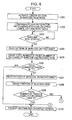
- Figs. 6 and 7 are flowcharts showing an example of the process operation by the mobile phone terminal 2 during the barcode read mode.
- the CPU 201 executes each step in the flowcharts of Figs. 6 and 7 according to the program for the barcode read mode stored in the ROM 202 while using the RAM 203 as a work area.
- the barcode read mode shown in Fig. 6 starts.
- the CPU 201 activates the camera section 209 in the barcode read mode (Step S201).
- a captured image from the camera section 209 is imported to the system bus 200 through the camera section interface 208.
- the user views the display screen of the LCD 207 of the mobile phone terminal 2 and adjusts the position of the mobile phone terminal 2 such that a two-dimensional barcode image displayed on the display screen 11 of the image display device 1 is displayed at the center of the display screen of the LCD 207.
- the CPU 201 confirms the auxiliary patterns for recognizing the upper, lower, left, and right corners from the captured image of the two-dimensional barcode image 12 imported from the camera section 209 (Step S202). Though not shown in this flowchart, when the OK key is operated and a barcode read start instruction is made in a state where the auxiliary patterns are not possible to be confirmed, a barcode image is not read, so the CPU 201 performs error display.
- Step S203 the CPU 201 waits for the barcode read start instruction according to the operation of the OK key by the user (Step S203).
- the CPU 201 reads the pattern image of the first sheet of the two-dimensional barcode image (Step S204).
- the CPU 201 acquires the import time of the first sheet of the two-dimensional barcode image from the time information from the clock circuit 212.
- the process for reading the two-dimensional barcode image in Step S204 includes a process for importing the captured image from the camera section 209 and performing decoding by the barcode decoding section 211 so as to confirm whether or not decoding is possible.
- a process for importing the captured image from the camera section 209 until decoding is possible with respect to the two-dimensional barcode image is included in the process of Step S204.
- Step S204 After the pattern image of the first sheet of the two-dimensional barcode image is read in Step S204, the total number of pages and the position of the pattern image of the first sheet of the two-dimensional barcode in the total number of pages are grasped from the page index pattern 123 (Step S205).
- Step S205 the CPU 201 grasps the total number of pages of the two-dimensional barcode image from the position of the total page count bar 126 in the page index pattern 123.
- the total page count bar 126 is positioned in the lateral bar display region 128F from among the seven lateral bar display regions 128A to 128G, so the total number of pages is grasped to be five.
- Step S205 the CPU 201 also grasps the position of the relevant page in the total number of pages from the position of the relevant page display bar 127 of the page index pattern 123.
- Step S206 determines whether or not the total number of pages grasped in Step S205 is "1" (Step S206). When it is determined in Step S206 that the total number of pages is "1", the CPU 201 determines that the reading of the two-dimensional barcode image ends, and displays information read from the two-dimensional barcode image on the display screen of the LCD 207 (Step S210). Then, the process routine ends.
- Step S206 When it is determined in Step S206 that the total number of pages is not "1", the CPU 201 reads the pattern image of the second sheet of the two-dimensional barcode image from the captured image from the camera section 209 (Step S207). The CPU 201 acquires the import time of the pattern image of the second sheet from the time information from the clock circuit 212.
- the process for reading the two-dimensional barcode image in Step S207 also includes a process for decoding the imported two-dimensional barcode image by the barcode decoding section 211 so as to confirm whether or not decoding is possible, similarly to the process of Step S204.
- a process for repetitively importing the two-dimensional barcode image until a two-dimensional barcode image capable of being decoded is obtained is also included.
- Step S207 the CPU 201 grasps the position of the pattern image of the second sheet in the total number of pages from the relevant page display bar 127 of the page index pattern 123 (Step S208).
- the CPU 201 determines whether the total number of pages of the two-dimensional barcode image is equal to or more than 3 (Step S209).
- Step S209 When it is determined in Step S209 that the total number of pages of the two-dimensional barcode image is less than 3, that is, 2, if the pattern image of the second sheet of the two-dimensional barcode image is read, it is determined that all the pages are read. Thus, the CPU 201 displays information read from the two-dimensional barcode image on the display screen of the LCD 207 (Step S210). Then, the process routine ends.
- Step S209 When it is determined in Step S209 that the total number of pages of the two-dimensional barcode image is equal to or more than 3, the CPU 201 calculates the import timing, that is, the capturing timing, of each of the remaining unread pages of the two-dimensional barcode image from the camera section 209, and generates and stores a capturing timing table based on the calculation result (Step S211).
- Step S211 will be described in connection with the two-dimensional barcode image 12 having five pages shown in Figs. 1A and 1B .
- Step S211 the CPU 201 first grasps the positions of the first and second sheets of the two-dimensional barcode image grasped in Steps S205 and S208 in the total number of pages. That is, the page numbers of the first and second sheets of the two-dimensional barcode image are grasped.
- the CPU 201 also grasps the capturing time of the first and second sheets of the two-dimensional barcode image acquired in Steps S204 and Step S207.
- the CPU 201 calculates the display time per page, that is, the page switching time of the two-dimensional barcode image, from the grasped relevant page information of each of the first and second sheets of the two-dimensional barcode image and information regarding the capturing time.
- the first sheet refers to the pattern image of the second page of the two-dimensional barcode image, and the capturing time thereof is 200 milliseconds since the barcode read mode starts in Step S203.
- the second sheet refers to the pattern image of the fourth page of the two-dimensional barcode image, and the capturing time thereof is 400 milliseconds since the barcode read mode starts in Step S203.
- the CPU 201 grasps the remaining unread pages of the two-dimensional barcode image from the total number of pages grasped in Step S205 and the page numbers of the first and second sheets of the two-dimensional barcode image.
- the remaining unread pages of the two-dimensional barcode image are the first page, the second page, and the fifth page.
- the CPU 201 predicts the capturing timing, at which each of the grasped remaining unread pages of the two-dimensional barcode image can be read fastest, by using the calculated page switching time T and information regarding the unread pages, and generates a capturing timing table.
- a capturing timing table shown in Fig. 9 is generated.
- the capturing timing table of Fig. 9 is generated as follows. That is, if it is assumed that the second page and the fourth page are calculated in the first round of the two-dimensional barcode image 12 having five pages in total, in the first round, the fifth page is predicted to be next presented 100 milliseconds after the fourth page is presented (that is, 500 milliseconds), so the fifth page is planned to be imported at the predicted time.
- the first page is predicted to be presented at the beginning of the second round of the two-dimensional barcode image 12, so the first page is planned to be imported at 600 milliseconds. Further, the third page is predicted to be presented at 800 milliseconds in the second round, so the third page is planned to be imported at 800 milliseconds.
- Step S211 if the capturing timing table for the unread pages is created, the CPU 201 tries to read the unread pages of the two-dimensional barcode image in accordance with the created capturing timing table (Step S212).
- the CPU 201 determines from the page index pattern of the two-dimensional barcode image imported in Step S212 whether or not a page is possible to be imported as predicted (Step S213), and when it is determined that a page is not possible to be imported as predicted, corrects and updates the capturing timing table (Step S214).
- Step S214 when the CPU 201 tries to import the fifth page at 500 milliseconds but the fourth page is acquired at that time, the page switching time T increases longer than 100 milliseconds, and the capturing timing table is created again.
- the page switching time T decreases shorter than 100 milliseconds, and the capturing timing table is created again.
- the CPU 201 updates the capturing timing table such that the unread fifth page is acquired after the third page is acquired in the second round.
- the acquired first page is an unread page, so the CPU 201 reads the first page. Then, the CPU 201 grasps the third page and the fifth page as the unread pages, and updates the capturing timing table such that the third page and the fifth page are acquired at photographing time to be predicted in the second round.
- Step S212 when a page of the two-dimensional barcode image is tried to be imported and as shown in Fig. 10 , the capturing timing becomes the transition time between the pages, the capturing timing table is corrected as follows.
- both the relevant page display bars 127 of the previous and subsequent pages are photographed in the portion of the relevant page display bar 127 of the page index pattern of the imported image.
- the relevant page display bar 127 of the previous page is displayed in black darker than the relevant page display bar 127 of the subsequent page. Further, when the capturing timing leans toward the subsequent page, the relevant page display bar 127 of the subsequent page is displayed in black darker than the relevant page display bar 127 of the previous page.
- the capturing timing when the capturing timing is the transition time of the previous and subsequent pages, the capturing timing can be appropriately corrected on the basis of the degree of shading of the relevant page display bars 127 of the previous and subsequent pages in the read image.
- Step S214 After the capturing timing table is corrected and updated in Step S214, the CPU 201 returns to Step S212, and repeats the processes of Step S212 and later.
- Step S213 When it is determined in Step S213 that a page is possible to be acquired as predicted, the CPU 201 determines whether or not all the pages of the two-dimensional barcode image are acquired (Step S215). In Step S215, when it is determined that unread pages still remain, the CPU 201 returns to Step S212 without correcting and updating the capturing timing table, and repeats the processes of Step S212 and later.
- Step S215 When it is determined in Step S215 that all the pages are read, the CPU 201 progresses to Step S210, and decodes code information corresponding to the read two-dimensional barcode image to generate display information, and display the display information on the display screen so as to present the code information. Then, the process routine ends.
- a capturing timing table is created for all of the unread pages, and the pages are read on the basis of the capturing timing table.
- the capturing timing may be predicted for each of the unread pages, and the unread pages may be sequentially read.
- the CPU 201 grasps all the unread pages, predicts the capturing timing for a page which is read with the nearest timing as the next capturing timing, and tries to read the relevant page with the predicted capturing timing.
- the page switching time interval is corrected according to whether a page is possible to be acquired as predicted or not by using the trial result. Then, the capturing timing is predicted for a page which is read with the next nearest timing by using the corrected page switching time interval, and the relevant page is tried to be read with the predicted capturing timing.
- the two-dimensional barcode image in the foregoing embodiment is configured such that the page index pattern is formed in a portion of the pattern image of the square two-dimensional barcode.
- the square pattern image 300 of a two-dimensional barcode may be identical to the typical two-dimensional barcode image (barcode pattern), and a page index pattern 400 may be formed in a region different from the square pattern image 300 of the two-dimensional barcode.
- a pair of the square pattern image 300 of the two-dimensional barcode and the page index pattern 400 a two-dimensional barcode image having multiple pages is formed.
- the page index pattern 400 is identical to the page index pattern 123 in the example of Figs. 1A and 1B . That is, lateral bar display regions 404A to 404G are set between the upper and lower bars of a U-shaped pattern 401. One of the lateral bar display regions 404A to 404G becomes a total page count bar 402, and another becomes a relevant page display bar 403.
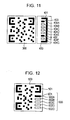
- the examples of the two-dimensional barcode image are given assuming that the total number of pages is not fixed. Meanwhile, in the case of a two-dimensional barcode image having a fixed total number of pages, no total page count bar may be provided.
- a two-dimensional barcode image 500 of Fig. 12 is exemplified.
- the total number of pages is five.
- a page index pattern 600 is formed in a portion of the square two-dimensional barcode image 500.
- the page index pattern of the two-dimensional barcode image 500 is provided below an auxiliary pattern 501 indicating the upper right corner, and five lateral bar display regions 602A, 602B, 602C, 602D, and 602E arranged in the vertical direction are used as the display region of the relevant page display bar 601.
- Fig. 12 is the two-dimensional barcode image of the first page.
- the two-dimensional barcode image has a fixed total number of pages, so when the amount of code information is small, all of the pages may not be used. In this case, with regard to an unused page, a code pattern indicating that the relevant page is unused is formed.
- the page index information in the two-dimensional barcode image is indicated by the page index pattern including the total page count bar and the relevant page display bar.
- the page index information may be included in the code information and consequently included in the barcode pattern, instead of being presented so as to be easily recognizable as an image pattern.
- the total page count bar or the relevant page display bar may not be displayed as an image pattern.
- a two-dimensional barcode image has a comparatively small number of pages
- a two-dimensional barcode image having a larger number of pages for example, 100 pages
- a pattern image is a two-dimensional barcode image, such as a QR code (Registered Trademark) or the like
- a pattern image to be read is not limited to the two-dimensional barcode image, and any pattern image may be used insofar as it is presented in the form of multiple pages.
- the apparatus for reading a pattern image is not limited to the mobile phone terminal, and any apparatus may be used as the apparatus for reading a pattern image insofar as it includes a capturing function.
Landscapes
- Physics & Mathematics (AREA)
- Engineering & Computer Science (AREA)
- Electromagnetism (AREA)
- General Physics & Mathematics (AREA)
- Theoretical Computer Science (AREA)
- General Health & Medical Sciences (AREA)
- Health & Medical Sciences (AREA)
- Toxicology (AREA)
- Artificial Intelligence (AREA)
- Computer Vision & Pattern Recognition (AREA)
- User Interface Of Digital Computer (AREA)
- Facsimile Scanning Arrangements (AREA)
- Image Input (AREA)
- Information Transfer Between Computers (AREA)
- Telephone Function (AREA)
Claims (8)
- Procédé de capture et de lecture d'une image à motifs comportant au moins trois pages générée à partir d'informations préétablies à l'aide d'un moyen de capture (209) monté dans un appareil de lecture, l'image à motifs étant configurée de manière à ce que chaque page contienne des informations de page pertinente indiquant une position de la page pertinente et à ce que les pages s'affichent sur un écran d'affichage (207) de façon séquentielle et successive selon un intervalle de temps et de façon cyclique et répétitive, le procédé comprenant une étape consistant à :si deux pages de l'image à motifs ont été lues, amener l'appareil de lecture à prédire une chronologie de capture par le moyen de capture (209) pour chacune des pages non lues restantes de l'image à motifs à partir d'un intervalle de temps de capture entre les deux pages de l'image à motifs et des informations de page pertinente de chacune des deux pages de l'image à motifs, et à lancer une commande de sorte que chacune des pages non lues restantes de l'image à motifs soit capturée et lue par le moyen de capture selon la chronologie de capture prédite.
- Procédé selon la revendication 1,
dans lequel chaque page de l'image à motifs contient des informations de compte total de pages indiquant le nombre total de pages, et
l'étape consistant à amener l'appareil de lecture à prédire la chronologie de capture pour chacune des pages non lues restantes et à lancer une commande pour lire chaque page non lue restante de l'image à motifs comporte les étapes consistant à :si les deux pages de l'image à motifs ont été lues, prédire la chronologie de capture par le moyen de capture (209) pour chacune des pages non lues restantes de l'image à motifs, et créer une table de chronologie de capture prédite pour chaque page de l'image à motifs ; etcapturer et lire les pages non lues restantes de l'image à motifs par le moyen de capture (209) conformément à la table de chronologie de capture créée à l'étape consistant à prédire la chronologie de capture. - Procédé selon la revendication 2, comprenant en outre une étape consistant à :corriger la chronologie de capture prédite dans la table si chaque page de l'image à motifs n'a pas été lue conformément à la chronologie de capture dans la table à l'étape consistant à capturer et lire les pages non lues restantes de l'image à motifs.
- Procédé selon la revendication 1,
dans lequel, à l'étape consistant à amener l'appareil de lecture à prédire la chronologie de capture pour chacune des pages non lues restantes et à lancer une commande pour lire chaque page non lue restante de l'image à motifs, un processus de prédiction et de lecture est exécuté page par page. - Procédé selon la revendication 4,
dans lequel, à l'étape consistant à amener l'appareil de lecture à prédire la chronologie de capture pour chacune des pages non lues restantes et à lancer une commande pour lire chaque page non lue restantes de l'image à motifs, suite à l'exécution de la lecture de l'image à motifs, si la page de l'image à motifs n'est pas lue comme prédit, le fait que l'image à motifs de la page n'a pas été lue comme prédit est pris en compte dans la prédiction d'une chronologie de capture lors de l'exécution de la prochaine lecture. - Procédé selon la revendication 1,
dans lequel l'image à motifs est un motif d'un code-barres à deux dimensions. - Appareil de lecture d'une image à motifs comportant au moins trois pages générée à partir d'informations préétablies, l'image à motifs étant configurée de manière à ce que chaque page contienne des informations de page pertinente indiquant une position de la page pertinente et à ce que les pages s'affichent sur un écran d'affichage (207) de façon séquentielle et successive selon un intervalle de temps et de façon cyclique et répétitive, l'appareil comprenant :un moyen de capture (209) permettant de capturer l'image à motifs affichée sur l'écran d'affichage (207) ;un moyen de lecture (211) permettant de lire les informations préétablies et les informations de page pertinente à partir de l'image à motifs capturée par le moyen de capture ; etun moyen de commande (201) permettant, si deux pages de l'image à motifs ont été lues par le moyen de lecture, de prédire une chronologie de capture par le moyen de capture pour chacune des pages non lues restantes de l'image à motifs à partir d'un intervalle de temps de capture entre les deux pages de l'image à motifs et des informations de page pertinente de chacune des deux pages de l'image à motifs, et de commander l'appareil de capture (209) de manière à imager chacune des pages non lues restantes de l'image à motifs selon la chronologie de capture prédite.
- Programme d'ordinateur contenant des instructions lisibles par ordinateur dont le chargement sur un ordinateur amène l'ordinateur à mettre en oeuvre un procédé selon la revendication 1.
Applications Claiming Priority (1)
| Application Number | Priority Date | Filing Date | Title |
|---|---|---|---|
| JP2008290431A JP2010117871A (ja) | 2008-11-13 | 2008-11-13 | パターン画像の読み取り方法、パターン画像の読み取り装置、情報処理方法およびパターン画像の読み取りプログラム |
Publications (3)
| Publication Number | Publication Date |
|---|---|
| EP2187336A2 EP2187336A2 (fr) | 2010-05-19 |
| EP2187336A3 EP2187336A3 (fr) | 2011-10-12 |
| EP2187336B1 true EP2187336B1 (fr) | 2014-09-17 |
Family
ID=41428999
Family Applications (1)
| Application Number | Title | Priority Date | Filing Date |
|---|---|---|---|
| EP09252551.8A Not-in-force EP2187336B1 (fr) | 2008-11-13 | 2009-11-04 | Procédé de lecture d'images à motifs, appareil pour la lecture d'images à motifs, procédé de traitement d'informations et programme de lecture d'images à motifs |
Country Status (4)
| Country | Link |
|---|---|
| US (1) | US8720779B2 (fr) |
| EP (1) | EP2187336B1 (fr) |
| JP (1) | JP2010117871A (fr) |
| CN (1) | CN101739544B (fr) |
Families Citing this family (37)
| Publication number | Priority date | Publication date | Assignee | Title |
|---|---|---|---|---|
| US8532632B2 (en) * | 2011-05-16 | 2013-09-10 | Wesley Boudville | Cellphone changing an electronic display that contains a barcode |
| CN103650383B (zh) | 2012-05-24 | 2017-04-12 | 松下电器(美国)知识产权公司 | 信息通信方法 |
| US8770484B2 (en) * | 2012-09-21 | 2014-07-08 | Alcatel Lucent | Data exchange using streamed barcodes |
| EP2930595A4 (fr) * | 2012-12-05 | 2016-07-27 | Kenji Yoshida | Interface de commande de système de gestion d'installation |
| US8988574B2 (en) | 2012-12-27 | 2015-03-24 | Panasonic Intellectual Property Corporation Of America | Information communication method for obtaining information using bright line image |
| US9142152B2 (en) * | 2012-12-21 | 2015-09-22 | Hewlett-Packard Development Company, L.P. | Display diagnostics using two-dimensional barcodes |
| US9252878B2 (en) | 2012-12-27 | 2016-02-02 | Panasonic Intellectual Property Corporation Of America | Information communication method |
| US9608727B2 (en) | 2012-12-27 | 2017-03-28 | Panasonic Intellectual Property Corporation Of America | Switched pixel visible light transmitting method, apparatus and program |
| EP2940889B1 (fr) | 2012-12-27 | 2019-07-31 | Panasonic Intellectual Property Corporation of America | Procédé d'affichage de signal de communication par lumière visible et dispositif d'affichage |
| US8922666B2 (en) | 2012-12-27 | 2014-12-30 | Panasonic Intellectual Property Corporation Of America | Information communication method |
| US9088360B2 (en) | 2012-12-27 | 2015-07-21 | Panasonic Intellectual Property Corporation Of America | Information communication method |
| SG11201504987SA (en) * | 2012-12-27 | 2015-07-30 | Panasonic Ip Corp America | Information communication method |
| US10530486B2 (en) | 2012-12-27 | 2020-01-07 | Panasonic Intellectual Property Corporation Of America | Transmitting method, transmitting apparatus, and program |
| US10523876B2 (en) | 2012-12-27 | 2019-12-31 | Panasonic Intellectual Property Corporation Of America | Information communication method |
| US10303945B2 (en) | 2012-12-27 | 2019-05-28 | Panasonic Intellectual Property Corporation Of America | Display method and display apparatus |
| US10951310B2 (en) | 2012-12-27 | 2021-03-16 | Panasonic Intellectual Property Corporation Of America | Communication method, communication device, and transmitter |
| US9087349B2 (en) | 2012-12-27 | 2015-07-21 | Panasonic Intellectual Property Corporation Of America | Information communication method |
| US9560284B2 (en) | 2012-12-27 | 2017-01-31 | Panasonic Intellectual Property Corporation Of America | Information communication method for obtaining information specified by striped pattern of bright lines |
| SG10201609857SA (en) | 2012-12-27 | 2017-01-27 | Panasonic Ip Corp America | Information communication method |
| US9608725B2 (en) | 2012-12-27 | 2017-03-28 | Panasonic Intellectual Property Corporation Of America | Information processing program, reception program, and information processing apparatus |
| WO2014103158A1 (fr) | 2012-12-27 | 2014-07-03 | パナソニック株式会社 | Procédé d'affichage vidéo |
| CN104871452B (zh) | 2012-12-27 | 2018-04-27 | 松下电器(美国)知识产权公司 | 可视光通信方法及可视光通信装置 |
| WO2014103341A1 (fr) | 2012-12-27 | 2014-07-03 | パナソニック株式会社 | Procédé de communication d'informations |
| KR20140108749A (ko) * | 2013-02-27 | 2014-09-15 | 한국전자통신연구원 | 프라이버시 보호형 문서 인증 정보 생성 장치 및 이를 이용한 프라이버시 보호형 문서 인증 방법 |
| US10325282B2 (en) | 2013-11-27 | 2019-06-18 | At&T Intellectual Property I, L.P. | Dynamic machine-readable codes |
| JP5976240B2 (ja) * | 2014-01-31 | 2016-08-23 | 三菱電機株式会社 | 送信装置、受信装置及び情報処理システム |
| JP6361406B2 (ja) * | 2014-09-17 | 2018-07-25 | 株式会社デンソーウェーブ | 情報コード読取システム |
| JP6195175B2 (ja) * | 2014-10-31 | 2017-09-13 | 地球ソリューションズ株式会社 | 情報表示・読取システム |
| GB2533630B (en) | 2014-12-24 | 2019-09-04 | Ge Aviat Systems Ltd | System and method of integrity checking digitally displayed data |
| TWI544419B (zh) * | 2015-11-20 | 2016-08-01 | 王碩騰 | 二維條碼之編碼方法、解碼方法與電子裝置 |
| JP6972729B2 (ja) * | 2017-07-24 | 2021-11-24 | コニカミノルタ株式会社 | 画像表示システム、資料提供支援装置、資料取得装置、資料提供支援方法、およびコンピュータプログラム |
| JP7030288B2 (ja) * | 2017-09-19 | 2022-03-07 | 株式会社サテライトオフィス | 携帯移動端末用アプリケーションソフトウェア |
| JP2019114917A (ja) * | 2017-12-22 | 2019-07-11 | 株式会社東芝 | 画像処理装置及びプログラム |
| JP2019144793A (ja) * | 2018-02-20 | 2019-08-29 | 富士ゼロックス株式会社 | 情報処理装置及びプログラム |
| JP7455026B2 (ja) | 2020-08-27 | 2024-03-25 | 株式会社Jr西日本テクシア | 操作システム |
| CN112131222B (zh) * | 2020-09-22 | 2024-04-02 | 深圳赛安特技术服务有限公司 | 消息读取状态数据的存储方法、装置、介质及电子设备 |
| CN112651475B (zh) * | 2021-01-06 | 2022-09-23 | 北京字节跳动网络技术有限公司 | 二维码显示方法、装置、设备及介质 |
Family Cites Families (7)
| Publication number | Priority date | Publication date | Assignee | Title |
|---|---|---|---|---|
| US7070098B1 (en) * | 2000-05-24 | 2006-07-04 | Silverbrook Res Pty Ltd | Printed page tag encoder |
| JP2004078351A (ja) * | 2002-08-12 | 2004-03-11 | Sharp Corp | バーコード作成装置、バーコード読取装置および動画像バーコード |
| JP2005182629A (ja) * | 2003-12-22 | 2005-07-07 | Sony Corp | 情報送受信システムおよび方法、送信装置および送信方法、受信装置および受信方法、並びにプログラム |
| WO2006017229A2 (fr) * | 2004-07-12 | 2006-02-16 | Kyos Systems Inc. | Interface informatique utilisant des formulaires |
| JP4487690B2 (ja) * | 2004-08-27 | 2010-06-23 | ソニー株式会社 | 表示装置、通信システムおよび方法 |
| JP4810918B2 (ja) | 2005-08-01 | 2011-11-09 | 富士ゼロックス株式会社 | コードパターン画像生成装置及び方法、コードパターン画像読取装置及び方法、及びコードパターン画像媒体 |
| JP4520935B2 (ja) | 2005-12-07 | 2010-08-11 | シャープ株式会社 | 情報転送システム及び情報転送方法 |
-
2008
- 2008-11-13 JP JP2008290431A patent/JP2010117871A/ja active Pending
-
2009
- 2009-11-04 EP EP09252551.8A patent/EP2187336B1/fr not_active Not-in-force
- 2009-11-12 US US12/616,838 patent/US8720779B2/en not_active Expired - Fee Related
- 2009-11-13 CN CN200910206455.8A patent/CN101739544B/zh not_active Expired - Fee Related
Also Published As
| Publication number | Publication date |
|---|---|
| US8720779B2 (en) | 2014-05-13 |
| US20100116888A1 (en) | 2010-05-13 |
| EP2187336A2 (fr) | 2010-05-19 |
| CN101739544A (zh) | 2010-06-16 |
| JP2010117871A (ja) | 2010-05-27 |
| CN101739544B (zh) | 2014-10-01 |
| EP2187336A3 (fr) | 2011-10-12 |
Similar Documents
| Publication | Publication Date | Title |
|---|---|---|
| EP2187336B1 (fr) | Procédé de lecture d'images à motifs, appareil pour la lecture d'images à motifs, procédé de traitement d'informations et programme de lecture d'images à motifs | |
| KR101541263B1 (ko) | 사용자 동작 커맨드들을 실행하기 위한 방법 및 장치 | |
| EP3018557A1 (fr) | Système de balayage de codes à barres utilisant un dispositif portable avec caméra incorporée | |
| JP7054341B2 (ja) | 通信装置およびその制御方法 | |
| CN102857619A (zh) | 电子名片分享方法及系统 | |
| JP2004094353A (ja) | Pda/携帯電話画面多重一次元バーコードの読み取りを基礎とする身分識別システム | |
| CN104143105A (zh) | 一种图形识别方法、装置、终端设备及系统 | |
| JP2014211709A (ja) | 1次元バーコードリサイズ装置、方法およびプログラムならびに1次元バーコードシステム | |
| US20140141716A1 (en) | Method for Rapid Information Synchronization Using Near Field Communication | |
| JP2007122351A (ja) | 画像読取システム | |
| JP2012133069A (ja) | マルチディスプレイシステム及びその制御方法 | |
| WO2017119191A1 (fr) | Dispositif terminal, procédé de traitement d'informations et support d'enregistrement | |
| RU97199U1 (ru) | Система, мобильное устройство и считывающее устройство для передачи текстовой информации с помощью графических изображений | |
| KR20130059836A (ko) | 휴대용 단말기에서 코드 이미지를 획득하기 위한 장치 및 방법 | |
| KR20120082334A (ko) | 이력 데이터 분석을 통한 모바일 코드 복호화 오류 복구 장치 및 방법 | |
| EP2838030B1 (fr) | Appareil terminal mobile, système de communication mobile, procédé et programme de communication mobile | |
| KR20050032748A (ko) | 이동통신단말기 및 그 이동통신단말기 간의 데이터 전송방법 | |
| CN108038668B (zh) | 一种协同办公的方法和设备、终端及可读存储介质 | |
| CN106254654A (zh) | 移动终端及数据传输方法 | |
| JP2009048411A (ja) | 情報提供装置及びコンピュータプログラム | |
| JP2013073309A (ja) | 画像注目領域抽出方法、並びに当該方法を実現する電子機器、システム、及びプログラム | |
| JP2022095701A (ja) | 通信装置およびその制御方法 | |
| KR100685969B1 (ko) | 바코드를 이용한 데이터 교환 장치 및 교환 방법 | |
| KR20120050315A (ko) | 통신 단말기를 이용하여 데이타베이스 처리가 가능한 코드 스캐닝방법 | |
| JP6420132B2 (ja) | 電子広告表示システム、電子広告表示装置、及び携帯端末 |
Legal Events
| Date | Code | Title | Description |
|---|---|---|---|
| PUAI | Public reference made under article 153(3) epc to a published international application that has entered the european phase |
Free format text: ORIGINAL CODE: 0009012 |
|
| 17P | Request for examination filed |
Effective date: 20091119 |
|
| AK | Designated contracting states |
Kind code of ref document: A2 Designated state(s): AT BE BG CH CY CZ DE DK EE ES FI FR GB GR HR HU IE IS IT LI LT LU LV MC MK MT NL NO PL PT RO SE SI SK SM TR |
|
| AX | Request for extension of the european patent |
Extension state: AL BA RS |
|
| PUAL | Search report despatched |
Free format text: ORIGINAL CODE: 0009013 |
|
| RIC1 | Information provided on ipc code assigned before grant |
Ipc: G06K 19/06 20060101ALI20110811BHEP Ipc: G06K 7/10 20060101AFI20110811BHEP |
|
| RIC1 | Information provided on ipc code assigned before grant |
Ipc: G06K 19/06 20060101ALI20110831BHEP Ipc: G06K 7/10 20060101AFI20110831BHEP |
|
| AK | Designated contracting states |
Kind code of ref document: A3 Designated state(s): AT BE BG CH CY CZ DE DK EE ES FI FR GB GR HR HU IE IS IT LI LT LU LV MC MK MT NL NO PL PT RO SE SI SK SM TR |
|
| AX | Request for extension of the european patent |
Extension state: AL BA RS |
|
| RIC1 | Information provided on ipc code assigned before grant |
Ipc: G06K 7/10 20060101AFI20110902BHEP Ipc: G06K 19/06 20060101ALI20110902BHEP |
|
| 17Q | First examination report despatched |
Effective date: 20110926 |
|
| RAP1 | Party data changed (applicant data changed or rights of an application transferred) |
Owner name: SONY MOBILE COMMUNICATIONS JAPAN, INC. |
|
| GRAP | Despatch of communication of intention to grant a patent |
Free format text: ORIGINAL CODE: EPIDOSNIGR1 |
|
| RIC1 | Information provided on ipc code assigned before grant |
Ipc: G06K 7/14 20060101ALI20140307BHEP Ipc: G06K 19/06 20060101ALI20140307BHEP Ipc: G06K 7/10 20060101AFI20140307BHEP |
|
| INTG | Intention to grant announced |
Effective date: 20140411 |
|
| GRAS | Grant fee paid |
Free format text: ORIGINAL CODE: EPIDOSNIGR3 |
|
| GRAA | (expected) grant |
Free format text: ORIGINAL CODE: 0009210 |
|
| AK | Designated contracting states |
Kind code of ref document: B1 Designated state(s): AT BE BG CH CY CZ DE DK EE ES FI FR GB GR HR HU IE IS IT LI LT LU LV MC MK MT NL NO PL PT RO SE SI SK SM TR |
|
| REG | Reference to a national code |
Ref country code: GB Ref legal event code: FG4D |
|
| REG | Reference to a national code |
Ref country code: CH Ref legal event code: EP |
|
| REG | Reference to a national code |
Ref country code: IE Ref legal event code: FG4D |
|
| REG | Reference to a national code |
Ref country code: AT Ref legal event code: REF Ref document number: 687980 Country of ref document: AT Kind code of ref document: T Effective date: 20141015 |
|
| REG | Reference to a national code |
Ref country code: DE Ref legal event code: R096 Ref document number: 602009026697 Country of ref document: DE Effective date: 20141030 |
|
| REG | Reference to a national code |
Ref country code: NL Ref legal event code: T3 |
|
| PG25 | Lapsed in a contracting state [announced via postgrant information from national office to epo] |
Ref country code: NO Free format text: LAPSE BECAUSE OF FAILURE TO SUBMIT A TRANSLATION OF THE DESCRIPTION OR TO PAY THE FEE WITHIN THE PRESCRIBED TIME-LIMIT Effective date: 20141217 Ref country code: LT Free format text: LAPSE BECAUSE OF FAILURE TO SUBMIT A TRANSLATION OF THE DESCRIPTION OR TO PAY THE FEE WITHIN THE PRESCRIBED TIME-LIMIT Effective date: 20140917 Ref country code: FI Free format text: LAPSE BECAUSE OF FAILURE TO SUBMIT A TRANSLATION OF THE DESCRIPTION OR TO PAY THE FEE WITHIN THE PRESCRIBED TIME-LIMIT Effective date: 20140917 Ref country code: SE Free format text: LAPSE BECAUSE OF FAILURE TO SUBMIT A TRANSLATION OF THE DESCRIPTION OR TO PAY THE FEE WITHIN THE PRESCRIBED TIME-LIMIT Effective date: 20140917 Ref country code: GR Free format text: LAPSE BECAUSE OF FAILURE TO SUBMIT A TRANSLATION OF THE DESCRIPTION OR TO PAY THE FEE WITHIN THE PRESCRIBED TIME-LIMIT Effective date: 20141218 |
|
| REG | Reference to a national code |
Ref country code: LT Ref legal event code: MG4D |
|
| PG25 | Lapsed in a contracting state [announced via postgrant information from national office to epo] |
Ref country code: LV Free format text: LAPSE BECAUSE OF FAILURE TO SUBMIT A TRANSLATION OF THE DESCRIPTION OR TO PAY THE FEE WITHIN THE PRESCRIBED TIME-LIMIT Effective date: 20140917 Ref country code: HR Free format text: LAPSE BECAUSE OF FAILURE TO SUBMIT A TRANSLATION OF THE DESCRIPTION OR TO PAY THE FEE WITHIN THE PRESCRIBED TIME-LIMIT Effective date: 20140917 Ref country code: CY Free format text: LAPSE BECAUSE OF FAILURE TO SUBMIT A TRANSLATION OF THE DESCRIPTION OR TO PAY THE FEE WITHIN THE PRESCRIBED TIME-LIMIT Effective date: 20140917 |
|
| REG | Reference to a national code |
Ref country code: AT Ref legal event code: MK05 Ref document number: 687980 Country of ref document: AT Kind code of ref document: T Effective date: 20140917 |
|
| PG25 | Lapsed in a contracting state [announced via postgrant information from national office to epo] |
Ref country code: PT Free format text: LAPSE BECAUSE OF FAILURE TO SUBMIT A TRANSLATION OF THE DESCRIPTION OR TO PAY THE FEE WITHIN THE PRESCRIBED TIME-LIMIT Effective date: 20150119 Ref country code: SK Free format text: LAPSE BECAUSE OF FAILURE TO SUBMIT A TRANSLATION OF THE DESCRIPTION OR TO PAY THE FEE WITHIN THE PRESCRIBED TIME-LIMIT Effective date: 20140917 Ref country code: IS Free format text: LAPSE BECAUSE OF FAILURE TO SUBMIT A TRANSLATION OF THE DESCRIPTION OR TO PAY THE FEE WITHIN THE PRESCRIBED TIME-LIMIT Effective date: 20150117 Ref country code: CZ Free format text: LAPSE BECAUSE OF FAILURE TO SUBMIT A TRANSLATION OF THE DESCRIPTION OR TO PAY THE FEE WITHIN THE PRESCRIBED TIME-LIMIT Effective date: 20140917 Ref country code: RO Free format text: LAPSE BECAUSE OF FAILURE TO SUBMIT A TRANSLATION OF THE DESCRIPTION OR TO PAY THE FEE WITHIN THE PRESCRIBED TIME-LIMIT Effective date: 20140917 Ref country code: ES Free format text: LAPSE BECAUSE OF FAILURE TO SUBMIT A TRANSLATION OF THE DESCRIPTION OR TO PAY THE FEE WITHIN THE PRESCRIBED TIME-LIMIT Effective date: 20140917 Ref country code: EE Free format text: LAPSE BECAUSE OF FAILURE TO SUBMIT A TRANSLATION OF THE DESCRIPTION OR TO PAY THE FEE WITHIN THE PRESCRIBED TIME-LIMIT Effective date: 20140917 |
|
| PG25 | Lapsed in a contracting state [announced via postgrant information from national office to epo] |
Ref country code: AT Free format text: LAPSE BECAUSE OF FAILURE TO SUBMIT A TRANSLATION OF THE DESCRIPTION OR TO PAY THE FEE WITHIN THE PRESCRIBED TIME-LIMIT Effective date: 20140917 Ref country code: PL Free format text: LAPSE BECAUSE OF FAILURE TO SUBMIT A TRANSLATION OF THE DESCRIPTION OR TO PAY THE FEE WITHIN THE PRESCRIBED TIME-LIMIT Effective date: 20140917 |
|
| REG | Reference to a national code |
Ref country code: DE Ref legal event code: R097 Ref document number: 602009026697 Country of ref document: DE |
|
| PG25 | Lapsed in a contracting state [announced via postgrant information from national office to epo] |
Ref country code: LU Free format text: LAPSE BECAUSE OF FAILURE TO SUBMIT A TRANSLATION OF THE DESCRIPTION OR TO PAY THE FEE WITHIN THE PRESCRIBED TIME-LIMIT Effective date: 20141104 Ref country code: MC Free format text: LAPSE BECAUSE OF FAILURE TO SUBMIT A TRANSLATION OF THE DESCRIPTION OR TO PAY THE FEE WITHIN THE PRESCRIBED TIME-LIMIT Effective date: 20140917 Ref country code: BE Free format text: LAPSE BECAUSE OF NON-PAYMENT OF DUE FEES Effective date: 20141130 |
|
| REG | Reference to a national code |
Ref country code: CH Ref legal event code: PL |
|
| PLBE | No opposition filed within time limit |
Free format text: ORIGINAL CODE: 0009261 |
|
| STAA | Information on the status of an ep patent application or granted ep patent |
Free format text: STATUS: NO OPPOSITION FILED WITHIN TIME LIMIT |
|
| PG25 | Lapsed in a contracting state [announced via postgrant information from national office to epo] |
Ref country code: CH Free format text: LAPSE BECAUSE OF NON-PAYMENT OF DUE FEES Effective date: 20141130 Ref country code: LI Free format text: LAPSE BECAUSE OF NON-PAYMENT OF DUE FEES Effective date: 20141130 Ref country code: DK Free format text: LAPSE BECAUSE OF FAILURE TO SUBMIT A TRANSLATION OF THE DESCRIPTION OR TO PAY THE FEE WITHIN THE PRESCRIBED TIME-LIMIT Effective date: 20140917 |
|
| 26N | No opposition filed |
Effective date: 20150618 |
|
| GBPC | Gb: european patent ceased through non-payment of renewal fee |
Effective date: 20141217 |
|
| REG | Reference to a national code |
Ref country code: IE Ref legal event code: MM4A |
|
| REG | Reference to a national code |
Ref country code: FR Ref legal event code: ST Effective date: 20150731 |
|
| PG25 | Lapsed in a contracting state [announced via postgrant information from national office to epo] |
Ref country code: IT Free format text: LAPSE BECAUSE OF FAILURE TO SUBMIT A TRANSLATION OF THE DESCRIPTION OR TO PAY THE FEE WITHIN THE PRESCRIBED TIME-LIMIT Effective date: 20140917 |
|
| PG25 | Lapsed in a contracting state [announced via postgrant information from national office to epo] |
Ref country code: IE Free format text: LAPSE BECAUSE OF NON-PAYMENT OF DUE FEES Effective date: 20141104 Ref country code: GB Free format text: LAPSE BECAUSE OF NON-PAYMENT OF DUE FEES Effective date: 20141217 |
|
| PG25 | Lapsed in a contracting state [announced via postgrant information from national office to epo] |
Ref country code: SI Free format text: LAPSE BECAUSE OF FAILURE TO SUBMIT A TRANSLATION OF THE DESCRIPTION OR TO PAY THE FEE WITHIN THE PRESCRIBED TIME-LIMIT Effective date: 20140917 Ref country code: FR Free format text: LAPSE BECAUSE OF NON-PAYMENT OF DUE FEES Effective date: 20141201 |
|
| PGFP | Annual fee paid to national office [announced via postgrant information from national office to epo] |
Ref country code: DE Payment date: 20151119 Year of fee payment: 7 |
|
| PGFP | Annual fee paid to national office [announced via postgrant information from national office to epo] |
Ref country code: NL Payment date: 20151118 Year of fee payment: 7 |
|
| PG25 | Lapsed in a contracting state [announced via postgrant information from national office to epo] |
Ref country code: SM Free format text: LAPSE BECAUSE OF FAILURE TO SUBMIT A TRANSLATION OF THE DESCRIPTION OR TO PAY THE FEE WITHIN THE PRESCRIBED TIME-LIMIT Effective date: 20140917 |
|
| PG25 | Lapsed in a contracting state [announced via postgrant information from national office to epo] |
Ref country code: BG Free format text: LAPSE BECAUSE OF FAILURE TO SUBMIT A TRANSLATION OF THE DESCRIPTION OR TO PAY THE FEE WITHIN THE PRESCRIBED TIME-LIMIT Effective date: 20140917 |
|
| PG25 | Lapsed in a contracting state [announced via postgrant information from national office to epo] |
Ref country code: HU Free format text: LAPSE BECAUSE OF FAILURE TO SUBMIT A TRANSLATION OF THE DESCRIPTION OR TO PAY THE FEE WITHIN THE PRESCRIBED TIME-LIMIT; INVALID AB INITIO Effective date: 20091104 Ref country code: MT Free format text: LAPSE BECAUSE OF FAILURE TO SUBMIT A TRANSLATION OF THE DESCRIPTION OR TO PAY THE FEE WITHIN THE PRESCRIBED TIME-LIMIT Effective date: 20140917 Ref country code: TR Free format text: LAPSE BECAUSE OF FAILURE TO SUBMIT A TRANSLATION OF THE DESCRIPTION OR TO PAY THE FEE WITHIN THE PRESCRIBED TIME-LIMIT Effective date: 20140917 |
|
| REG | Reference to a national code |
Ref country code: DE Ref legal event code: R119 Ref document number: 602009026697 Country of ref document: DE |
|
| REG | Reference to a national code |
Ref country code: NL Ref legal event code: MM Effective date: 20161201 |
|
| PG25 | Lapsed in a contracting state [announced via postgrant information from national office to epo] |
Ref country code: NL Free format text: LAPSE BECAUSE OF NON-PAYMENT OF DUE FEES Effective date: 20161201 |
|
| PG25 | Lapsed in a contracting state [announced via postgrant information from national office to epo] |
Ref country code: DE Free format text: LAPSE BECAUSE OF NON-PAYMENT OF DUE FEES Effective date: 20170601 |
|
| PG25 | Lapsed in a contracting state [announced via postgrant information from national office to epo] |
Ref country code: MK Free format text: LAPSE BECAUSE OF FAILURE TO SUBMIT A TRANSLATION OF THE DESCRIPTION OR TO PAY THE FEE WITHIN THE PRESCRIBED TIME-LIMIT Effective date: 20140917 |