EP2186605B1 - Ausziehkupplung für Einspritzdüsen - Google Patents
Ausziehkupplung für Einspritzdüsen Download PDFInfo
- Publication number
- EP2186605B1 EP2186605B1 EP20090013254 EP09013254A EP2186605B1 EP 2186605 B1 EP2186605 B1 EP 2186605B1 EP 20090013254 EP20090013254 EP 20090013254 EP 09013254 A EP09013254 A EP 09013254A EP 2186605 B1 EP2186605 B1 EP 2186605B1
- Authority
- EP
- European Patent Office
- Prior art keywords
- gripper elements
- internal thread
- head part
- injection nozzle
- thread
- Prior art date
- Legal status (The legal status is an assumption and is not a legal conclusion. Google has not performed a legal analysis and makes no representation as to the accuracy of the status listed.)
- Not-in-force
Links
- 230000008878 coupling Effects 0.000 title claims description 38
- 238000010168 coupling process Methods 0.000 title claims description 38
- 238000005859 coupling reaction Methods 0.000 title claims description 38
- 238000002347 injection Methods 0.000 title claims description 38
- 239000007924 injection Substances 0.000 title claims description 38
- 238000000605 extraction Methods 0.000 description 18
- 230000003068 static effect Effects 0.000 description 2
- 230000006978 adaptation Effects 0.000 description 1
- 230000004323 axial length Effects 0.000 description 1
- 239000011248 coating agent Substances 0.000 description 1
- 238000000576 coating method Methods 0.000 description 1
- 230000006835 compression Effects 0.000 description 1
- 238000007906 compression Methods 0.000 description 1
- 238000010276 construction Methods 0.000 description 1
- 230000006378 damage Effects 0.000 description 1
- 230000000694 effects Effects 0.000 description 1
- 239000000446 fuel Substances 0.000 description 1
- 239000007779 soft material Substances 0.000 description 1
- 230000006641 stabilisation Effects 0.000 description 1
- 238000011105 stabilization Methods 0.000 description 1
Images


Classifications
-
- B—PERFORMING OPERATIONS; TRANSPORTING
- B25—HAND TOOLS; PORTABLE POWER-DRIVEN TOOLS; MANIPULATORS
- B25B—TOOLS OR BENCH DEVICES NOT OTHERWISE PROVIDED FOR, FOR FASTENING, CONNECTING, DISENGAGING OR HOLDING
- B25B27/00—Hand tools, specially adapted for fitting together or separating parts or objects whether or not involving some deformation, not otherwise provided for
- B25B27/0035—Hand tools, specially adapted for fitting together or separating parts or objects whether or not involving some deformation, not otherwise provided for for motor-vehicles
-
- B—PERFORMING OPERATIONS; TRANSPORTING
- B25—HAND TOOLS; PORTABLE POWER-DRIVEN TOOLS; MANIPULATORS
- B25B—TOOLS OR BENCH DEVICES NOT OTHERWISE PROVIDED FOR, FOR FASTENING, CONNECTING, DISENGAGING OR HOLDING
- B25B27/00—Hand tools, specially adapted for fitting together or separating parts or objects whether or not involving some deformation, not otherwise provided for
- B25B27/02—Hand tools, specially adapted for fitting together or separating parts or objects whether or not involving some deformation, not otherwise provided for for connecting objects by press fit or detaching same
- B25B27/023—Hand tools, specially adapted for fitting together or separating parts or objects whether or not involving some deformation, not otherwise provided for for connecting objects by press fit or detaching same using screws
-
- B—PERFORMING OPERATIONS; TRANSPORTING
- B25—HAND TOOLS; PORTABLE POWER-DRIVEN TOOLS; MANIPULATORS
- B25B—TOOLS OR BENCH DEVICES NOT OTHERWISE PROVIDED FOR, FOR FASTENING, CONNECTING, DISENGAGING OR HOLDING
- B25B27/00—Hand tools, specially adapted for fitting together or separating parts or objects whether or not involving some deformation, not otherwise provided for
- B25B27/02—Hand tools, specially adapted for fitting together or separating parts or objects whether or not involving some deformation, not otherwise provided for for connecting objects by press fit or detaching same
- B25B27/026—Hand tools, specially adapted for fitting together or separating parts or objects whether or not involving some deformation, not otherwise provided for for connecting objects by press fit or detaching same fluid driven
Definitions
- the invention relates to a pull-out with a body for a seated in a cylinder head injector, which is coupled on the one hand with a pulling device and on the other hand with an external thread of a head portion of the injector.
- a pulling device is provided with a support cylinder. Between the support cylinder and a valve cover placed on the cylinder head, a separate, divided support ring is provided, the annular portions of which are individually placed on the valve cover in the surrounding region of the nozzle.
- a Buchspindel described which, on the one hand in cooperation with a pull nut and the support cylinder, an extraction of the injection nozzle causes.
- a traction spindle can also be part of a hydraulic cylinder through which correspondingly greater extraction forces can be applied.
- the threaded spindle toward the injection nozzle has a mounting thread which can be screwed into a corresponding internal thread of the injection nozzle or a head part of the injection nozzle after removal of the electrical connection part of the injection nozzle. Due to the fact that such internal threads are usually designed to be extremely robust and stable, such an internal thread and large tensile forces can be applied to the injection nozzle, so that it can be pulled out of the cylinder head even with extremely tight fit.
- a device for extracting an injection nozzle which has a hydraulically actuated tractor spindle.
- a kind of union nut is still provided, which is provided with an internal thread. This union nut is held axially on a radially projecting projection of the threaded spindle.
- this can be screwed onto an external thread of the head part of the injection nozzle, so that an additional hold can be achieved. This is especially at extremely high extraction forces of advantage, since a tearing the internal thread and / or the external thread of the head part of the injection nozzle is reliably avoided.
- injectors are also known from the prior art, in which the external thread is formed as a so-called. Fine thread and accordingly has only a very small thread depth of a few tenths of a millimeter. This in turn means that this fine thread can tear at extremely high tensile forces.
- the invention has the object to design a pull-out such that it is on the one hand fixedly coupled to the external thread of the head portion of the injector and on the other hand, extremely high tensile forces can be applied to the injector.
- the inventive design a Ausziehkupplung is provided, with which extremely high extraction forces can be applied.
- the main body of the extraction coupling is provided with an internal thread, which is fittingly screwed onto the external thread of the head part of the injection nozzle.
- the main body in the axial extension of this internal thread on a plurality of radially elastically deformable gripper elements, which are braced against the headboard.
- the internal thread in the axial region of the radially elastically deformable gripper elements in particular is arranged approximately centrally.
- the main body of the extraction coupling with its gripper elements can be screwed onto the external thread of the head part of the injection nozzle.
- gripper extensions of the gripper elements can still be located axially following the internal thread arranged in the region of the gripper elements, so that an additional frictional or form-locking grip of the extractor coupling on the head part of the injection nozzle can be achieved.
- the gripper elements have in their free end region radially inwardly projecting pull strips.
- Such an embodiment is preferably provided when corresponding undercuts are provided in the region of the head part of the injection nozzle. With these undercuts, the radially inwardly projecting pull strips are correspondingly engageable, so that here is a tight fit connection after the clamping of the gripper elements is reached.
- the internal thread can be arranged both in a non-deformable part of the base body and in a deformable part of the gripper elements of the base body.
- the gripper elements have to the head part directed towards clamping surfaces, which are surface-treated.
- a surface coating is an increased static friction between these clamping surfaces and the head portion of the injector reachable, so that even by this measure increased extraction forces can be applied.
- the gripper elements in the connection to the internal thread to the head part directed towards profiled surfaces, in particular thread-like jagged surfaces. Also by this measure increased extraction forces can be applied to an injector or on the headboard.
- the gripper elements may be provided axially opposite with a coupling thread, via which the pull-out coupling with the pulling device can be coupled. Due to this extremely simple configuration, the pull-out is optional, for example, with a pull spindle, for example, after DE 20 2004 009 755 U1 or with a hydraulic cylinder according to the document DE 20 2004 006 602 U1 coupled.
- the extraction coupling has an external thread on which a clamping nut can be screwed.
- This clamping nut has a conical inner contour towards the gripper elements, which cooperates with a conical outer circumferential surface formed by the gripper elements.
- a pull-out 1 is shown in the Fig. 1 to 3 . It shows Fig. 1 a side view, Fig. 2 a bottom view II Fig. 1 and Fig. 3 a vertical section III-III of the extractor 1 from Fig. 2 ,
- the pull-out coupling forms a base body 2 which has an outer hexagon 3 in its upper one end region, via which the main body 2 or the pull-out coupling 1 can be driven in rotation by means of a corresponding key tool.
- the main body 2 has an external thread 4, onto which a clamping nut can be screwed, as will be explained in more detail later.
- a total of six radially elastically adjustable gripper elements 5 are provided in the present embodiment, which are separated accordingly by separating slots 6 from each other. Through the dividing slots 6, the radially elastic adjustability is achieved.
- the gripper elements 5 together form a conical lateral surface 7, so that the gripper elements 5 can be radially compressed by means of an annular or conical clamping element.
- an internal thread 8 is provided approximately centrally in the region of the gripper elements 5 in the axial direction, via which the extraction coupling 1 or the base body 2 can be screwed onto a corresponding external thread of a head part of an injection nozzle.
- cylinder-section-shaped clamping surfaces 9 which are adapted in their dimensions to the dimensions of a head portion of an ejected nozzle.
- the base body For coupling the pull-out coupling 1 with a pulling device, the base body has a corresponding internal thread 10 in its upper end region.
- a clamping nut 15 is shown, which is provided for the radial clamping of the gripper elements 5.
- the clamping nut 15 has in its upper end region also has a hexagon socket 16, via which the clamping nut 15 is correspondingly driven in rotation by means of a key tool.
- This clamping nut 15 has in the present embodiment an outer cylindrical surface 17 on.
- the clamping nut 15 is provided with an internal thread 18, with which the clamping nut 15 can be screwed onto the external thread 4 of the pull-out coupling 1 or of the base body 2.
- Vertically downwards adjoins the internal thread a conically enlarged inner contour 19, the shape of which is adapted to the conical shape of the conical lateral surface 7 of the gripper elements 5.
- clamping surfaces 9 may be surface-treated, so that the static friction is improved at a head portion of an injection nozzle.
- Fig. 6 shows the upper end portion of an injection nozzle 25, which has an upper head portion 26.
- an external thread 27 is provided, on which the pull-out coupling 1 or the base body 2 with the internal thread 8 of its gripper elements 5 can be screwed.
- a receiving groove 28 is provided in the lower end region of the external thread 27, which serves in the present embodiment of the injection nozzle 25 for receiving an O-ring seal 29.
- Fig. 7 now shows a vertical section of the Ausziehkupplung 1 with its base body 2 in its on the head portion 26 of the injector 25 correctly scheduled state.
- the gripper elements 5 lie with their inner clamping surfaces 9 flat against a cylinder portion 30 of the head part 26 of the injection nozzle 25.
- the internal thread 8 of the gripper elements 5 is fixedly connected to the external thread 27 of the head part 26 of the injection nozzle 25 in connection.
- the clamping nut 15 is screwed onto the external thread 4 of the base body 2 and braced vertically downward in the direction of the arrow 31 against the gripper elements 5.
- a pulling spindle 35 As a pulling device, the lower end of a pulling spindle 35 can be seen in the present embodiment, which is screwed into the internal thread 10 of the main body 2 and the pull-out 1 accordingly.
- This tension spindle 35, the tensile forces for example by means of a pull nut in conjunction with a support cylinder, as is known from the prior art, or by means of a hydraulic cylinder with a corresponding design of a counter-holder on the pull-out 1 apply.
- the extraction coupling 1 off Fig. 8 has in contrast to the pull-out 1 Fig. 1 additional radially inwardly directed tension strips 11, which are arranged in the lower end region of the respectively associated gripper element 5. These drawbars 11 are engageable with corresponding undercuts of this head part in a corresponding embodiment of a head portion of an injection nozzle, which is not explicitly shown in the drawing.
- the extraction coupling 1 off Fig. 9 also differs in this lower end of the gripper elements 5 of the two embodiments according to the Fig. 1 to 3 respectively.
- Fig. 8 In the lower end region, the gripper elements 5 are equipped on the inside with a profiled surface, in particular with a thread-like serrated surface structure 12. With this surface structure 12 is achieved at least to a small extent to a friction caused by the "pressing" of the gripper elements 5 against the head part still a kind of form closure, so that in this way the possible extraction forces are further increased.
- Such a configuration may, for example, also for the head part 26 with its cylinder portion 30 of the injection nozzle 25 from Fig. 7 be used.
- the prerequisite for an increase in the tensile effect is that this cylinder section 30 is made of a "relatively" soft material, but at least not surface-hardened.
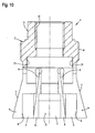
- Fig. 10 shows a further embodiment of a pull-out 1, wherein the internal thread 13 for coupling with the external thread 27 of the head portion 26 of the injection nozzle 25 from Fig. 7 is arranged in the non-deformable part of the base body 2 of the extraction coupling 1.
- the cylinder portion 30 of the injector 25 must for the use of this embodiment according to Fig. 10 axial length be formed (not shown in the drawing). In this embodiment, therefore, this internal thread 13 when tightening the clamping nut 15 from the 4 and 5 not clamped radially against the external thread 27 of the injection nozzle 25.
- the design of the further elements, in particular the gripper elements 5, corresponds to the embodiment of the embodiment of the pull-out 1 from Fig. 1 , However, it is also conceivable here that this embodiment according to the Fig. 10 the pull-out also with drawstrings 11 or with a profiled surface in particular an internal thread 12 of the two embodiments of the 8 and 9 Is provided.
- this embodiment according to the Fig. 10 the pull-out also with drawstrings 11 or with a profiled surface in particular an internal thread 12 of the two embodiments of the 8 and 9 Is provided.
- increased tensile forces can be applied to an injection nozzle during the extraction process by means of the radially elastically tensionable gripper elements, so that destruction, in particular of a thread formed as a male thread of the head part of the injection nozzle is reliably prevented.
Landscapes
- Engineering & Computer Science (AREA)
- Mechanical Engineering (AREA)
- Catching Or Destruction (AREA)
- Working Measures On Existing Buildindgs (AREA)
- Coating Apparatus (AREA)
- Nozzles (AREA)
Description
- Die Erfindung betrifft eine Ausziehkupplung mit einem Grundkörper für eine in einem Zylinderkopf sitzende Einspritzdüse, welche einerseits mit einer Zugvorrichtung und andererseits mit einem Außengewinde eines Kopfteils der Einspritzdüse koppelbar ist.
- Vorrichtungen zum Ausziehen von Einspritzdüsen sind gemeinhin aus dem Stand der Technik bekannt. Hierzu sei beispielhaft auf die beiden Druckschriften
DE 20 2004 009 755 U1 und dieDE 20 2004 006 602 U1 verwiesen. - Bei der Vorrichtung der
DE 20 2004 009 755 U1 zum Ausziehen einer auch als Düsenstock bezeichneten Einspritzdüse ist eine Zugvorrichtung mit einem Stützzylinder vorgesehen. Zwischen dem Stützzylinder und einem auf den Zylinderkopf aufgesetzten Ventildeckel ist ein separater, geteilter Stützring vorgesehen, dessen Ringabschnitte im Umgebungsbereich des Düsenstockes einzeln auf den Ventildeckel aufsetzbar sind. Als Ausziehvorrichtung ist beim Gegenstand derDE 20 2004 009 755 U1 eine Zugspindel beschrieben, welche einerseits im Zusammenwirken mit einer Zugmutter und dem Stützzylinder ein Ausziehen der Einspritzdüse bewirkt. Andererseits kann eine solche Zugspindel auch Bestandteil eines Hydraulikzylinders sein, durch welchen dementsprechend größere Ausziehkräfte aufbringbar sind. Als Ausziehkupplung zur Kopplung dieser Gewindespindel mit der Einspritzdüse weist die Gewindespindel zur Einspritzdüse hin ein Montagegewinde auf, welches nach dem Entfernen des elektrischen Anschlussteils der Einspritzdüse in ein entsprechendes Innengewinde der Einspritzdüse bzw. eines Kopfteils der Einspritzdüse einschraubbar ist. Aufgrund der Tatsache, dass solche Innengewinde in der Regel äußerst robust und stabil ausgebildet sind, können über ein solches Innengewinde auch große Zugkräfte auf die Einspritzdüse aufgebracht werden, so dass diese auch bei äußerst festsitzendem Halt aus dem Zylinderkopf ausgezogen werden kann. - Im Weiteren ist aus der
DE 20 2004 006 602 U1 welche die Merkmale des Oberbegriffs von Anspruch 1 umfasst, eine Vorrichtung zum Ausziehen einer Einspritzdüse bekannt, welche eine hydraulisch betätigbare Zugspindel aufweist. Auch diese Zugspindel weist beim Gegenstand derDE 20 2004 006 602 U1 ein Kupplungsgewinde als Ausziehkupplung auf, welche entsprechend in ein Innengewinde des Kopfteils der Einspritzdüse feststehend einschraubbar ist. Zusätzlich zu diesem Außengewinde ist noch eine Art Überwurfmutter vorgesehen, welche mit einem Innengewinde versehen ist. Diese Überwurfmutter wird axial an einem radial vorstehenden Vorsprung der Gewindespindel gehalten. Entsprechend der Ausgestaltung des Innengewindes dieser Überwurfmutter ist diese auf ein Außengewinde des Kopfteils der Einspritzdüse aufschraubbar, so dass ein zusätzlicher Halt erreichbar ist. Dies ist insbesondere bei äußerst hohen Ausziehkräften von Vorteil, da ein Ausreißen des Innengewindes und/oder des Außengewindes des Kopfteiles der Einspritzdüse sicher vermieden wird. - Nachteilig ist bei den beiden genannten Konstruktionen, dass das Innengewinde der Einspritzdüse durch Entfernen des Düseneinsatzes der Einspritzdüse zugänglich gemacht werden muss.
- Deshalb wäre vorteilhaft, lediglich die Überwurfmutter der
DE 20 2004 006 602 U1 einzusetzen oder zumindest ein ähnlich gestaltetes Kupplungselement, welches entsprechend nur mit dem Außengewinde des Kopfteils der Einspritzdüse verschraubt wird. - Aus dem Stand der Technik sind jedoch auch Einspritzdüsen bekannt, bei welchen das Außengewinde als sog. Feingewinde ausgebildet ist und dementsprechend eine nur äußerst geringe Gewindetiefe von einigen Zehntel-Millimetern aufweist. Dies bedeutet wiederum, dass dieses Feingewinde bei äußerst hohen Zugkräften ausreißen kann.
- Dementsprechend liegt der Erfindung die Aufgabe zugrunde, eine Ausziehkupplung derart zu gestalten, dass diese einerseits feststehend mit dem Außengewinde des Kopfteils der Einspritzdüse koppelbar ist und über welche andererseits äußerst hohe Zugkräfte auf die Einspritzdüse aufbringbar sind.
- Die Aufgabe wird erfindungsgemäß mit den Merkmalen des Anspruches 1 gelöst.
- Durch die erfindungsgemäße Ausgestaltung wird eine Ausziehkupplung zur Verfügung gestellt, mit welcher äußerst hohe Ausziehkräfte aufbringbar sind. Dazu ist einerseits der Grundkörper der Ausziehkupplung mit einem Innengewinde versehen, welches passend auf das Außengewinde des Kopfteils der Einspritzdüse aufschraubbar ist. Zusätzlich zu diesem Innengewinde weist der Grundkörper in axialer Verlängerung zu diesem Innengewinde mehrere radial elastisch verformbare Greiferelemente auf, welche gegen das Kopfteil verspannbar sind. So kann durch dieses radiale Verspannen dieser Greiferelemente gegen das Kopfteil ein zusätzlicher Halt aufgrund der Reibmomente oder auch aufgrund von evtl. vorgesehenen Formschlusselementen erreicht werden. Damit erhöht sich bei gleichzeitig präzisem Ansetzen der Ausziehkupplung an der Einspritzdüse die aufbringbare Ausziehkraft. Als Zugvorrichtungen kommen hier verschiedene aus dem Stand der Technik bekannte Zugvorrichtungen in Betracht. So sind hier einerseits Zugspindeln in herkömmlicher Art und Weise einsetzbar und andererseits auch entsprechend mit der Ausziehkupplung koppelbare Hydraulikzylinder.
- Weitere vorteilhafte Ausgestaltungen der Erfindung sind den weiteren Unteransprüchen entnehmbar.
- So kann gemäß Anspruch 2 vorgesehen sein, dass das Innengewinde im axialen Bereich der radial elastisch verformbaren Greiferelemente, insbesondere etwa mittig angeordnet ist. Dies bedeutet, dass bei einer derartigen Ausgestaltung der Grundkörper der Ausziehkupplung mit seinen Greiferelementen auf das Außengewinde des Kopfteils der Einspritzdüse aufschraubbar ist. Durch anschließendes radiales Verspannen dieser Greiferelemente wird das Gewindespiel - welches stets vorhanden ist - zwischen dem Innengewinde des Grundkörpers und dem Außengewinde des Kopfteils der Einspritzdüse minimiert, so dass die Tendenz des Ausreißens des Außengewindes oder des Innengewindes erheblich vermindert wird. Dabei können sich axial im Anschluss an das im Bereich der Greiferelemente angeordnete Innengewinde noch "Greiferfortsätze" der Greiferelemente befinden, so dass ein zusätzlicher kraftschlüssiger oder formschlüssiger Halt der Ausziehkupplung am Kopfteil der Einspritzdüse erreichbar ist.
- Des Weiteren kann gemäß Anspruch 3 vorgesehen sein, dass die Greiferelemente in ihrem freien Endbereich radial nach innen vorstehende Zugleisten aufweisen. Eine solche Ausgestaltung ist vorzugsweise dann vorzusehen, wenn im Bereich des Kopfteils der Einspritzdüse entsprechende Hinterschneidungen vorgesehen sind. Mit diesen Hinterschneidungen sind entsprechend die radial nach innen vorstehenden Zugleisten in Eingriff bringbar, so dass hier eine festsitzende Formschlussverbindung nach dem Verspannen der Greiferelemente erreichbar ist. Dabei kann das Innengewinde sowohl in einem nicht verformbaren Teil des Grundkörpers als auch in einem verformbaren Teil der Greiferelemente des Grundkörpers angeordnet sein. ßßß
- Des Weiteren kann gemäß Anspruch 4 vorgesehen sein, dass die Greiferelemente zum Kopfteil hin gerichtete Klemmflächen aufweisen, welche oberflächenvergütet sind. Durch eine solche Oberflächenvergütung ist eine erhöhte Haftreibung zwischen diesen Klemmflächen und dem Kopfteil der Einspritzdüse erreichbar, so dass auch durch diese Maßnahme erhöhte Ausziehkräfte aufbringbar sind.
- In einer weiteren Ausgestaltung kann gemäß Anspruch 5 vorgesehen sein, dass die Greiferelemente im Anschluss an das Innengewinde zum Kopfteil hin gerichtete, profilierte Oberflächen, insbesondere gewindeartig gezackte Oberflächen aufweisen. Auch durch diese Maßnahme können erhöhte Ausziehkräfte auf eine Einspritzdüse bzw. auf deren Kopfteil aufgebracht werden.
- Zur Kopplung der Ausziehkupplung mit einer Zugvorrichtung kann der Grundkörper der Ausziehkupplung gemäß Anspruch 6 den Greiferelementen axial gegenüberliegend mit einem Kupplungsgewinde versehen sein, über welche die Ausziehkupplung mit der Zugvorrichtung koppelbar ist. Durch diese äußerst einfache Ausgestaltung ist die Ausziehkupplung wahlweise beispielsweise mit einer Zugspindel beispielsweise nach der
DE 20 2004 009 755 U1 oder auch mit einem Hydraulikzylinder gemäß der DruckschriftDE 20 2004 006 602 U1 koppelbar. - Zum Verspannen der Greiferelemente gegen das Kopfteil kann gemäß Anspruch 7 vorgesehen sein, dass die Ausziehkupplung ein Außengewinde aufweist, auf welches eine Spannmutter aufschraubbar ist. Diese Spannmutter weist zu den Greiferelementen hin eine konische Innenkontur auf, welche mit einer von den Greiferelementen gebildete, konische äußere Mantelfläche zusammenwirkt. Damit können beim Festziehen der Spannmutter die Greiferelemente radial nach innen verstellt und somit gegen das Kopfteil verspannt werden. Diese Ausgestaltung ermöglicht insbesondere eine äußerst einfache Handhabung.
- Zusammenfassend ist festzustellen, dass durch die Kombination der radial elastisch verstellbaren Greiferelemente in Zusammenwirken mit dem Innengewinde äußerst hohe Ausziehkräfte auf das Kopfteil einer Einspritzdüse aufbringbar sind, ohne dass die Gefahr besteht, dass insbesondere das Außengewinde des Kopfteiles ausreißen kann oder beschädigt wird. Dabei ist insbesondere die Anordnung des Innengewindes im axialen Bereich der Greiferelemente von großem Vorteil, da das Innengewinde "mitverspannt" wird und somit eine Stabilisierung der Gewindeverbindung durch Verringerung des Gewindespiels erreichbar ist.
- Anhand der Zeichnung wird nachfolgend die Erfindung anhand einiger Ausführungsbeispiele näher erläutert. Es zeigt:
- Fig. 1
- eine Seitenansicht einer ersten Ausführungsvariante einer erfindungsgemäßen Ausziehkupplung;
- Fig. 2
- eine Unteransicht II der Ausziehkupplung aus
Fig. 1 ; - Fig. 3
- einen Vertikalschnitt III-III der Ausziehkupplung aus
Fig. 2 ; - Fig. 4
- eine Seitenansicht einer Spannmutter;
- Fig. 5
- einen Vertikalschnitt der Spannmutter aus
Fig. 4 ; - Fig. 6
- den oberen Endbereich einer Einspritzdüse mit einem Kopfteil, das ein Außengewinde aufweist in Seitenansicht;
- Fig. 7
- die Ausziehkupplung aus den
Fig. 1 bis 5 in ihrem am Kopfteil der Einspritzdüse ausFig. 6 angesetzten Zustand im Vertikalschnitt; - Fig. 8
- eine zweite Ausführungsvariante einer Ausziehkupplung im Vertikalschnitt;
- Fig. 9
- einen Vertikalschnitt einer dritten Ausführungsvariante einer Ausziehkupplung;
- Fig. 10
- eine vierte Ausführungsvariante einer erfindungsgemäßen Ausziehkupplung.
- An dieser Stelle sei angemerkt, dass alle Varianten der Ausziehkupplungen im Zusammenwirken mit der Spannmutter aus den
Fig. 4 und 5 einzusetzen sind. - In den
Fig. 1 bis 3 ist eine erste Ausführungsvariante einer Ausziehkupplung 1 dargestellt. Dabei zeigtFig. 1 eine Seitenansicht,Fig. 2 eine Unteransicht II ausFig. 1 und Fig. 3 einen Vertikalschnitt III-III der Ausziehkupplung 1 ausFig. 2 . Wie aus den drei Zeichnungsfiguren ersichtlich ist, bildet die Ausziehkupplung einen Grundkörper 2, welcher in seinem oberen einen Endbereich einen Außensechskant 3 aufweist, über welchen der Grundkörper 2 bzw. die Ausziehkupplung 1 drehend mittels eines entsprechenden Schlüsselwerkzeuges antreibbar ist. Diesem Außensechskantes 3 axial benachbart weist der Grundkörper 2 ein Außengewinde 4 auf, auf welches eine Spannmutter aufschraubbar ist, wie später noch näher erläutert wird. - Im Anschluss an dieses Außengewinde 4 sind beim vorliegenden Ausführungsbeispiel insgesamt sechs radial elastisch verstellbare Greiferelemente 5 vorgesehen, welche entsprechend durch Trennschlitze 6 voneinander getrennt sind. Durch die Trennschlitze 6 wird die radial elastische Verstellbarkeit erreicht. Dabei bilden die Greiferelemente 5 zusammen eine konische Mantelfläche 7, so dass die Greiferelemente 5 mittels eines ringförmigen oder ebenfalls konisch ausgebildeten Spannelementes radial zusammengedrückt werden können.
- Beim vorliegenden Ausführungsbeispiel ist im Bereich der Greiferelemente 5 in axialer Richtung etwa mittig ein Innengewinde 8 vorgesehen, über welches die Ausziehkupplung 1 bzw. der Grundkörper 2 auf ein entsprechendes Außengewinde eines Kopfteils einer Einspritzdüse aufschraubbar ist. In axialer Verlängerung dem Außensechskant 3 gegenüberliegend bilden die Greiferelemente zylinderabschnittsförmig verlaufende Klemmflächen 9, welche in ihren Abmessungen den Abmessungen eines Kopfteils einer auszuziehenden Einspritzdüse angepasst sind.
- Zur Kopplung der Ausziehkupplung 1 mit einer Zugvorrichtung weist der Grundkörper in seinem oberen Endbereich ein entsprechende Innengewinde 10 auf.
- In den
Fig. 4 und 5 ist beispielhaft eine Spannmutter 15 dargestellt, welche zum radialen Verspannen der Greiferelemente 5 vorgesehen ist. Die Spannmutter 15 weist in ihrem oberen Endbereich ebenfalls einen Außensechskant 16 aufweist, über welchen die Spannmutter 15 entsprechend mittels eines Schlüsselwerkzeuges drehend antreibbar ist. Diese Spannmutter 15 weist beim vorliegenden Ausführungsbeispiel eine äußere zylindrische Mantelfläche 17 auf. Innenseitig ist die Spannmutter 15 mit einem Innengewinde 18 versehen, mit welchem die Spannmutter 15 auf das Außengewinde 4 der Ausziehkupplung 1 bzw. des Grundkörpers 2 aufschraubbar ist. Vertikal nach unten schließt sich an das Innengewinde eine konisch erweiterte Innenkontur 19 an, deren Formgebung an den konischen Verlauf der konischen Mantelfläche 7 der Greiferelemente 5 angepasst ist. - Beim Anziehen der Spannmutter 15 über deren Außensechskant 16 kann die Ausziehkupplung 1 bzw. der Grundkörper 2 über den Außensechskant 3 des Grundkörpers 2 gegengehalten werden, so dass ein sicheres Aufschrauben der Spannmutter 15 mit ihrer konischen Innenkontur 19 auf die konischen Mantelflächen 7 der Greiferelemente 5 ermöglicht wird.
- Die in den
Fig. 2 und 3 dargestellten Klemmflächen 9 können oberflächenvergütet sein, so dass die Haftreibung an einem Kopfteil einer Einspritzdüse verbessert wird. -
Fig. 6 zeigt den oberen Endbereich einer Einspritzdüse 25, welche ein oberes Kopfteil 26 aufweist. Im oberen Endbereich dieses Kopfteiles 26 ist ein Außengewinde 27 vorgesehen, auf welches die Ausziehkupplung 1 bzw. der Grundkörper 2 mit dem Innengewinde 8 seiner Greiferelemente 5 aufschraubbar ist. Des Weiteren ist inFig. 6 noch der Kraftstoffanschlussstutzen 32 im Bereich des Kopfteiles 26 erkennbar. Des Weiteren ist im unteren Endbereich des Außengewindes 27 eine Aufnahmenut 28 vorgesehen, welche beim vorliegenden Ausführungsbeispiel der Einspritzdüse 25 zur Aufnahme einer O-Ringdichtung 29 dient. -
Fig. 7 zeigt nun einen vertikalen Teilschnitt der Ausziehkupplung 1 mit ihrem Grundkörper 2 in ihrem am Kopfteil 26 der Einspritzdüse 25 korrekt angesetzten Zustand. Es ist erkennbar, dass die Greiferelemente 5 mit ihren inneren Klemmflächen 9 flächig an einem Zylinderabschnitt 30 des Kopfteiles 26 der Einspritzdüse 25 anliegen. Dabei müssen hier nicht zwingend Klemmkräfte bewirkt werden. Jedoch steht das Innengewinde 8 der Greiferelemente 5 feststehend mit dem Außengewinde 27 des Kopfteiles 26 der Einspritzdüse 25 in Verbindung. Die Spannmutter 15 ist auf das Außengewinde 4 des Grundkörpers 2 aufgeschraubt und vertikal nach unten in Richtung des Pfeiles 31 gegen die Greiferelemente 5 verspannt. In dieser inFig. 7 dargestellten verspannten Position wird somit das Spiel zwischen dem Innengewinde 8 und dem Außengewinde 27 durch die radiale "Verpressung" der Greiferelemente 5 gegen das Kopfteil 26 derart verringert, dass höhere Auszugskräfte entgegen des Pfeiles 31 über diese Gewindeverbindung aufbringbar sind. Des Weiteren kann durch weiteres Anziehen der Spannmutter 15 (und/oder entsprechende Formanpassung der Klemmflächen 9) in Richtung des Pfeiles 31 eine zusätzliche Verspannung der über das Innengewinde 8 hinaus stehenden Abschnitte der Greiferelemente 5 mit ihren Klemmflächen 9 gegen den Zylinderabschnitt 30 des Kopfteils 26 bewirkt werden, wodurch ebenfalls die aufbringbaren Zugkräfte entgegen des Pfeiles 31 erhöht werden. - Als Zugvorrichtung ist beim vorliegenden Ausführungsbeispiel das untere Ende einer Zugspindel 35 erkennbar, welche entsprechend in das Innengewinde 10 des Grundkörpers 2 bzw. der Ausziehkupplung 1 eingeschraubt ist. Diese Zugspindel 35 kann die Zugkräfte beispielsweise mittels einer Zugmutter in Verbindung mit einem Stützzylinder, wie dies aus dem Stand der Technik bekannt ist, oder auch mittels eines Hydraulikzylinders bei entsprechender Ausgestaltung eines Gegenhalters auf die Ausziehkupplung 1 aufbringen.
- In den weiteren Zeichnungsfiguren 8 bis 10 sind drei weitere Ausführungsvarianten von Ausziehkupplungen beispielhaft dargestellt. Für die gleichen Bauelemente oder Bauteile sind hierbei auch die gleichen Bezugszeichen eingesetzt wie bei der Ausführungsvariante aus den
Fig. 1 bis 3 , so dass die Beschreibung zur Ausziehkupplung 1 aus denFig. 1 bis 3 sowie zuFig. 7 auch auf die Ausziehkupplungen 1 aus denFig. 8 bis 10 lesbar ist. Insoweit wird auch auf diese Beschreibung verwiesen. - Die Ausziehkupplung 1 aus
Fig. 8 weist im Unterschied zur Ausziehkupplung 1 ausFig. 1 zusätzliche radial nach innen gerichtete Zugleisten 11 auf, welche im unteren Endbereich des jeweils zugehörigen Greiferelementes 5 angeordnet sind. Diese Zugleisten 11 sind bei entsprechender Ausgestaltung eines Kopfteils einer Einspritzdüse mit entsprechenden Hinterschneidungen dieses Kopfteils in Eingriff bringbar, was in der Zeichnung nicht explizit dargestellt ist. - Die Ausziehkupplung 1 aus
Fig. 9 unterscheidet sich ebenfalls in diesem unteren Endbereich der Greiferelemente 5 von den beiden Ausgestaltungen nach denFig. 1 bis 3 bzw.Fig. 8 . Im unteren Endbereich sind die Greiferelemente 5 innenseitig mit einer profilierten Oberfläche, insbesondere mit einer gewindeartig gezackten Oberflächenstruktur 12 ausgestattet. Mit dieser Oberflächenstruktur 12 wird zu einer beim "Verpressen" der Greiferelemente 5 gegen das Kopfteil bewirkten Haftreibung noch eine Art Formschluss zumindest in geringem Maße erreicht, so dass hierdurch die möglichen Auszugskräfte weiter erhöht werden. Eine solche Ausgestaltung kann beispielsweise auch für das Kopfteil 26 mit seinem Zylinderabschnitt 30 der Einspritzdüse 25 ausFig. 7 eingesetzt werden. Voraussetzung für eine Erhöhung der Zugwirkung ist, dass dieser Zylinderabschnitt 30 aus einem "relativ" weichen Material besteht, zumindest jedoch nicht oberflächengehärtet ist. -
Fig. 10 zeigt eine weitere Ausführungsvariante einer Ausziehkupplung 1, bei welcher das Innengewinde 13 zur Kupplung mit dem Außengewinde 27 des Kopfteiles 26 der Einspritzdüse 25 ausFig. 7 im nicht verformbaren Teil des Grundkörpers 2 der Ausziehkupplung 1 angeordnet ist. Der Zylinderabschnitt 30 der Einspritzdüse 25 muss für den Einsatz dieser Ausführungsvariante nachFig. 10 axial länge ausgebildet sein (in der Zeichnung nicht näher dargestellt). Bei dieser Ausführungsvariante wird somit dieses Innengewinde 13 beim Anziehen der Spannmutter 15 aus denFig. 4 und 5 nicht radial gegen das Außengewinde 27 der Einspritzdüse 25 verspannt. - Die Ausgestaltung der weiteren Elemente, insbesondere der Greiferelemente 5, entspricht dabei der Ausgestaltung der Ausführungsvariante der Ausziehkupplung 1 aus
Fig. 1 . Es ist jedoch hier gleichfalls vorstellbar, dass diese Ausgestaltung nach derFig. 10 der Ausziehkupplung ebenfalls mit Zugleisten 11 oder auch mit einer profilierten Oberfläche insbesondere einem Innengewinde 12 der beiden Ausführungsvarianten aus denFig. 8 und 9 ausgestattet ist. Zusammenfassend ist erkennbar, dass durch die radialelastisch verspannbaren Greiferelemente erhöhte Zugkräfte auf eine Einspritzdüse beim Ausziehvorgang aufbringbar sind, so dass eine Zerstörung, insbesondere eines als Feingewinde ausgebildeten Außengewindes des Kopfteils der Einspritzdüse sicher verhindert wird.
Claims (7)
- Ausziehkupplung (1) mit einem Grundkörper (2) für eine in einem Zylinderkopf sitzende Einspritzdüse (25), welche einerseits mit einer Zugvorrichtung (35) und andererseits mit einem Außengewinde (27) eines Kopfteils (26) der Einspritzdüse (25) koppelbar ist, dadurch gekennzeichnet,
dass der Grundkörper (2) ein passend auf das Außengewinde aufschraubbares Innengewinde (8, 13) aufweist und,
dass der Grundkörper (2) in axialer Verlängerung zu seinem Innengewinde (8, 13) mit mehreren radialelastisch verformbaren Greiferelementen (5) versehen ist, welche gegen das Kopfteil (26) der Einspritzdüse (25) verspannbar sind. - Ausziehkupplung nach Anspruch 1, dadurch gekennzeichnet, dass das Innengewinde (8) in axialen Bereich der radialelastisch verformbaren Greiferelemente (5), insbesondere etwa mittig angeordnet ist.
- Ausziehkupplung nach Anspruch 1 oder 2, dadurch gekennzeichnet, dass die Greiferelemente (5) in ihrem freien Endbereich radial nach innen vorstehende Zugleisten (11) aufweisen.
- Ausziehkupplung nach Anspruch 1 oder 2, dadurch gekennzeichnet, dass die Greiferelemente (5) zum Kopfteil (26) hin gerichtete Klemmflächen (9) aufweisen, welche oberflächenvergütet sind.
- Ausziehkupplung nach Anspruch 1 oder 2, dadurch gekennzeichnet, das die Greiferelemente (5) im Anschluss an das Innengewinde (8) zum Kopfteil (26) hin gerichtete, profilierte Oberflächen, insbesondere gewindeartig gezackte Oberflächen (12) aufweisen.
- Ausziehkupplung nach einem der Ansprüche 1 bis 5, dadurch gekennzeichnet, dass der Grundkörper (2) den Greiferelementen (5) axial gegenüberliegend mit einem Innengewinde (10) versehen ist, über welches die Ausziehkupplung (1) mit der Zugvorrichtung (35) koppelbar ist.
- Ausziehkupplung nach einem der Ansprüche 1 bis 6, dadurch gekennzeichnet, dass der Grundkörper (2) ein Außengewinde (4) aufweist, auf welches eine Spannmutter (15) aufschraubbar ist und,
dass die Spannmutter (15) zu den Greiferelementen (5) hin eine konische Innenkontur (19) aufweist und,
dass die Greiferelemente (5) eine äußere, konische mit der Innenkontur (19) der Spannmutter (15) in Wirkverbindung bringbare Mantelfläche (7) bilden und mittels der Spannmutter (15) radial gegen das Kopfteil (26) verspannbar sind.
Applications Claiming Priority (1)
| Application Number | Priority Date | Filing Date | Title |
|---|---|---|---|
| DE200820015153 DE202008015153U1 (de) | 2008-11-14 | 2008-11-14 | Ausziehkupplung für Einspritzdüsen |
Publications (3)
| Publication Number | Publication Date |
|---|---|
| EP2186605A2 EP2186605A2 (de) | 2010-05-19 |
| EP2186605A3 EP2186605A3 (de) | 2012-05-23 |
| EP2186605B1 true EP2186605B1 (de) | 2015-03-04 |
Family
ID=40418589
Family Applications (1)
| Application Number | Title | Priority Date | Filing Date |
|---|---|---|---|
| EP20090013254 Not-in-force EP2186605B1 (de) | 2008-11-14 | 2009-10-21 | Ausziehkupplung für Einspritzdüsen |
Country Status (2)
| Country | Link |
|---|---|
| EP (1) | EP2186605B1 (de) |
| DE (1) | DE202008015153U1 (de) |
Families Citing this family (4)
| Publication number | Priority date | Publication date | Assignee | Title |
|---|---|---|---|---|
| DE102011007050B4 (de) * | 2011-04-08 | 2013-10-10 | Michael Müller | Werkzeug zum Lösen einer Bauteilkomponente |
| NL1038816C2 (nl) * | 2011-05-17 | 2012-11-20 | Jacob Matheus Maria Broek | Verstuivertrekker. |
| NL1039067C2 (nl) * | 2011-09-23 | 2013-03-26 | Jacob Matheus Maria Broek | Verstuivertrekker. |
| DE102014209668B4 (de) * | 2014-05-21 | 2016-08-25 | Bayerische Motoren Werke Aktiengesellschaft | Werkzeug zur Demontage eines Injektors einer Brennkraftmaschine |
Family Cites Families (4)
| Publication number | Priority date | Publication date | Assignee | Title |
|---|---|---|---|---|
| US3529497A (en) * | 1968-06-27 | 1970-09-22 | Daryl G Brooks | Dowel removing tool |
| DE20210759U1 (de) * | 2002-07-17 | 2002-11-07 | Weitner, Karl-Heinz, 85072 Eichstätt | Vorrichtung zum Ziehen von Einspritzdüsen |
| DE202004006602U1 (de) | 2004-04-23 | 2004-09-09 | Weitner, Werner | Vorrichtung zum Ziehen einer Einspritzdüse |
| DE202004009755U1 (de) | 2004-06-21 | 2004-09-16 | Klann-Spezial-Werkzeugbau-Gmbh | Vorrichtung zum Ausziehen eines Düsenstockes |
-
2008
- 2008-11-14 DE DE200820015153 patent/DE202008015153U1/de not_active Expired - Lifetime
-
2009
- 2009-10-21 EP EP20090013254 patent/EP2186605B1/de not_active Not-in-force
Also Published As
| Publication number | Publication date |
|---|---|
| EP2186605A2 (de) | 2010-05-19 |
| DE202008015153U1 (de) | 2009-03-05 |
| EP2186605A3 (de) | 2012-05-23 |
Similar Documents
| Publication | Publication Date | Title |
|---|---|---|
| DE3903354C1 (de) | ||
| DE2413750C2 (de) | Anschluß für Druckmittelleitungen | |
| EP1430245A1 (de) | Klemmverschraubung mit einer schraubhülse, einer gegenhülse und einem klemmeinsatz | |
| EP2369211B1 (de) | Vorrichtung für eine abgedichtete Durchführung von Langformteilen | |
| EP3658785B1 (de) | Spreizbolzen sowie verbindungsanordnung mit einem solchen spreizbolzen | |
| DE3100865C2 (de) | Spannanordnung zum Verbinden einer Nabe mit einer Welle | |
| WO2009097842A9 (de) | Steckvorrichtung | |
| DE10119445A1 (de) | Abziehwerkzeug | |
| EP2186605B1 (de) | Ausziehkupplung für Einspritzdüsen | |
| EP2699192B1 (de) | Zahnprothese | |
| DE202007009073U1 (de) | Vorrichtung zum Ausziehen einer Einspritzdüse | |
| WO1998055269A1 (de) | Vorsatz für einen schrauber | |
| DE4212771A1 (de) | Rohrverschraubung | |
| DE102011088293B4 (de) | Pratze zum Haltern eines Injektors | |
| EP1780854A1 (de) | Kabel- oder Schlauchverschraubung | |
| DE202006006421U1 (de) | Vorrichtung mit Stützring zum Ausziehen von Einspritzdüsen | |
| DE19944131B4 (de) | Klemmring | |
| DE29811259U1 (de) | Anschlußarmatur mit einem durch Schlitze in Haltezungen aufgeteilten Befestigungsvorsprung | |
| DE10245235B4 (de) | Spannsatz | |
| DE102010010209B4 (de) | Matrizenscheibe | |
| EP1992223A1 (de) | Gewindestollen | |
| DE102018100355B4 (de) | Kupplungsvorrichtung zur Verbindung eines Lasthebemittels mit einer Last | |
| DE3317146A1 (de) | Keilgetriebe | |
| DE102004004010B4 (de) | Teleskopierbares Staubsauger-Saugrohr mit freiliegendem Spiralkabel | |
| DE3131525A1 (de) | Loesbare befestigungsvorrichtung fuer lenkrollen |
Legal Events
| Date | Code | Title | Description |
|---|---|---|---|
| PUAI | Public reference made under article 153(3) epc to a published international application that has entered the european phase |
Free format text: ORIGINAL CODE: 0009012 |
|
| AK | Designated contracting states |
Kind code of ref document: A2 Designated state(s): AT BE BG CH CY CZ DE DK EE ES FI FR GB GR HR HU IE IS IT LI LT LU LV MC MK MT NL NO PL PT RO SE SI SK SM TR |
|
| AX | Request for extension of the european patent |
Extension state: AL BA RS |
|
| PUAL | Search report despatched |
Free format text: ORIGINAL CODE: 0009013 |
|
| AK | Designated contracting states |
Kind code of ref document: A3 Designated state(s): AT BE BG CH CY CZ DE DK EE ES FI FR GB GR HR HU IE IS IT LI LT LU LV MC MK MT NL NO PL PT RO SE SI SK SM TR |
|
| AX | Request for extension of the european patent |
Extension state: AL BA RS |
|
| RIC1 | Information provided on ipc code assigned before grant |
Ipc: B25B 27/02 20060101AFI20120417BHEP Ipc: B25B 27/00 20060101ALI20120417BHEP |
|
| 17P | Request for examination filed |
Effective date: 20121019 |
|
| GRAP | Despatch of communication of intention to grant a patent |
Free format text: ORIGINAL CODE: EPIDOSNIGR1 |
|
| RIC1 | Information provided on ipc code assigned before grant |
Ipc: B25B 27/02 20060101AFI20141020BHEP Ipc: B25B 27/00 20060101ALI20141020BHEP |
|
| INTG | Intention to grant announced |
Effective date: 20141120 |
|
| GRAS | Grant fee paid |
Free format text: ORIGINAL CODE: EPIDOSNIGR3 |
|
| GRAA | (expected) grant |
Free format text: ORIGINAL CODE: 0009210 |
|
| AK | Designated contracting states |
Kind code of ref document: B1 Designated state(s): AT BE BG CH CY CZ DE DK EE ES FI FR GB GR HR HU IE IS IT LI LT LU LV MC MK MT NL NO PL PT RO SE SI SK SM TR |
|
| REG | Reference to a national code |
Ref country code: GB Ref legal event code: FG4D Free format text: NOT ENGLISH |
|
| REG | Reference to a national code |
Ref country code: CH Ref legal event code: EP |
|
| REG | Reference to a national code |
Ref country code: IE Ref legal event code: FG4D Free format text: LANGUAGE OF EP DOCUMENT: GERMAN |
|
| REG | Reference to a national code |
Ref country code: AT Ref legal event code: REF Ref document number: 713422 Country of ref document: AT Kind code of ref document: T Effective date: 20150415 |
|
| REG | Reference to a national code |
Ref country code: DE Ref legal event code: R096 Ref document number: 502009010691 Country of ref document: DE Effective date: 20150416 |
|
| REG | Reference to a national code |
Ref country code: NL Ref legal event code: VDEP Effective date: 20150304 |
|
| PG25 | Lapsed in a contracting state [announced via postgrant information from national office to epo] |
Ref country code: LT Free format text: LAPSE BECAUSE OF FAILURE TO SUBMIT A TRANSLATION OF THE DESCRIPTION OR TO PAY THE FEE WITHIN THE PRESCRIBED TIME-LIMIT Effective date: 20150304 Ref country code: NO Free format text: LAPSE BECAUSE OF FAILURE TO SUBMIT A TRANSLATION OF THE DESCRIPTION OR TO PAY THE FEE WITHIN THE PRESCRIBED TIME-LIMIT Effective date: 20150604 Ref country code: FI Free format text: LAPSE BECAUSE OF FAILURE TO SUBMIT A TRANSLATION OF THE DESCRIPTION OR TO PAY THE FEE WITHIN THE PRESCRIBED TIME-LIMIT Effective date: 20150304 Ref country code: SE Free format text: LAPSE BECAUSE OF FAILURE TO SUBMIT A TRANSLATION OF THE DESCRIPTION OR TO PAY THE FEE WITHIN THE PRESCRIBED TIME-LIMIT Effective date: 20150304 Ref country code: HR Free format text: LAPSE BECAUSE OF FAILURE TO SUBMIT A TRANSLATION OF THE DESCRIPTION OR TO PAY THE FEE WITHIN THE PRESCRIBED TIME-LIMIT Effective date: 20150304 Ref country code: ES Free format text: LAPSE BECAUSE OF FAILURE TO SUBMIT A TRANSLATION OF THE DESCRIPTION OR TO PAY THE FEE WITHIN THE PRESCRIBED TIME-LIMIT Effective date: 20150304 |
|
| REG | Reference to a national code |
Ref country code: LT Ref legal event code: MG4D |
|
| PG25 | Lapsed in a contracting state [announced via postgrant information from national office to epo] |
Ref country code: LV Free format text: LAPSE BECAUSE OF FAILURE TO SUBMIT A TRANSLATION OF THE DESCRIPTION OR TO PAY THE FEE WITHIN THE PRESCRIBED TIME-LIMIT Effective date: 20150304 Ref country code: GR Free format text: LAPSE BECAUSE OF FAILURE TO SUBMIT A TRANSLATION OF THE DESCRIPTION OR TO PAY THE FEE WITHIN THE PRESCRIBED TIME-LIMIT Effective date: 20150605 |
|
| PG25 | Lapsed in a contracting state [announced via postgrant information from national office to epo] |
Ref country code: NL Free format text: LAPSE BECAUSE OF FAILURE TO SUBMIT A TRANSLATION OF THE DESCRIPTION OR TO PAY THE FEE WITHIN THE PRESCRIBED TIME-LIMIT Effective date: 20150304 |
|
| PG25 | Lapsed in a contracting state [announced via postgrant information from national office to epo] |
Ref country code: PT Free format text: LAPSE BECAUSE OF FAILURE TO SUBMIT A TRANSLATION OF THE DESCRIPTION OR TO PAY THE FEE WITHIN THE PRESCRIBED TIME-LIMIT Effective date: 20150706 Ref country code: EE Free format text: LAPSE BECAUSE OF FAILURE TO SUBMIT A TRANSLATION OF THE DESCRIPTION OR TO PAY THE FEE WITHIN THE PRESCRIBED TIME-LIMIT Effective date: 20150304 Ref country code: SK Free format text: LAPSE BECAUSE OF FAILURE TO SUBMIT A TRANSLATION OF THE DESCRIPTION OR TO PAY THE FEE WITHIN THE PRESCRIBED TIME-LIMIT Effective date: 20150304 Ref country code: CZ Free format text: LAPSE BECAUSE OF FAILURE TO SUBMIT A TRANSLATION OF THE DESCRIPTION OR TO PAY THE FEE WITHIN THE PRESCRIBED TIME-LIMIT Effective date: 20150304 Ref country code: RO Free format text: LAPSE BECAUSE OF FAILURE TO SUBMIT A TRANSLATION OF THE DESCRIPTION OR TO PAY THE FEE WITHIN THE PRESCRIBED TIME-LIMIT Effective date: 20150304 |
|
| PG25 | Lapsed in a contracting state [announced via postgrant information from national office to epo] |
Ref country code: IS Free format text: LAPSE BECAUSE OF FAILURE TO SUBMIT A TRANSLATION OF THE DESCRIPTION OR TO PAY THE FEE WITHIN THE PRESCRIBED TIME-LIMIT Effective date: 20150704 Ref country code: PL Free format text: LAPSE BECAUSE OF FAILURE TO SUBMIT A TRANSLATION OF THE DESCRIPTION OR TO PAY THE FEE WITHIN THE PRESCRIBED TIME-LIMIT Effective date: 20150304 |
|
| REG | Reference to a national code |
Ref country code: DE Ref legal event code: R097 Ref document number: 502009010691 Country of ref document: DE |
|
| PG25 | Lapsed in a contracting state [announced via postgrant information from national office to epo] |
Ref country code: IT Free format text: LAPSE BECAUSE OF FAILURE TO SUBMIT A TRANSLATION OF THE DESCRIPTION OR TO PAY THE FEE WITHIN THE PRESCRIBED TIME-LIMIT Effective date: 20150304 |
|
| PLBE | No opposition filed within time limit |
Free format text: ORIGINAL CODE: 0009261 |
|
| STAA | Information on the status of an ep patent application or granted ep patent |
Free format text: STATUS: NO OPPOSITION FILED WITHIN TIME LIMIT |
|
| PG25 | Lapsed in a contracting state [announced via postgrant information from national office to epo] |
Ref country code: DK Free format text: LAPSE BECAUSE OF FAILURE TO SUBMIT A TRANSLATION OF THE DESCRIPTION OR TO PAY THE FEE WITHIN THE PRESCRIBED TIME-LIMIT Effective date: 20150304 |
|
| 26N | No opposition filed |
Effective date: 20151207 |
|
| PG25 | Lapsed in a contracting state [announced via postgrant information from national office to epo] |
Ref country code: SI Free format text: LAPSE BECAUSE OF FAILURE TO SUBMIT A TRANSLATION OF THE DESCRIPTION OR TO PAY THE FEE WITHIN THE PRESCRIBED TIME-LIMIT Effective date: 20150304 |
|
| REG | Reference to a national code |
Ref country code: DE Ref legal event code: R082 Ref document number: 502009010691 Country of ref document: DE Representative=s name: NEYMEYER PATENTANWALTSKANZLEI, DE Ref country code: DE Ref legal event code: R081 Ref document number: 502009010691 Country of ref document: DE Owner name: GEDORE AUTOMOTIVE GMBH, DE Free format text: FORMER OWNER: KLANN-SPEZIAL-WERKZEUGBAU GMBH, 78166 DONAUESCHINGEN, DE |
|
| PG25 | Lapsed in a contracting state [announced via postgrant information from national office to epo] |
Ref country code: LU Free format text: LAPSE BECAUSE OF FAILURE TO SUBMIT A TRANSLATION OF THE DESCRIPTION OR TO PAY THE FEE WITHIN THE PRESCRIBED TIME-LIMIT Effective date: 20151021 |
|
| REG | Reference to a national code |
Ref country code: CH Ref legal event code: PL |
|
| GBPC | Gb: european patent ceased through non-payment of renewal fee |
Effective date: 20151021 |
|
| PG25 | Lapsed in a contracting state [announced via postgrant information from national office to epo] |
Ref country code: MC Free format text: LAPSE BECAUSE OF FAILURE TO SUBMIT A TRANSLATION OF THE DESCRIPTION OR TO PAY THE FEE WITHIN THE PRESCRIBED TIME-LIMIT Effective date: 20150304 |
|
| REG | Reference to a national code |
Ref country code: IE Ref legal event code: MM4A |
|
| PG25 | Lapsed in a contracting state [announced via postgrant information from national office to epo] |
Ref country code: CH Free format text: LAPSE BECAUSE OF NON-PAYMENT OF DUE FEES Effective date: 20151031 Ref country code: LI Free format text: LAPSE BECAUSE OF NON-PAYMENT OF DUE FEES Effective date: 20151031 Ref country code: GB Free format text: LAPSE BECAUSE OF NON-PAYMENT OF DUE FEES Effective date: 20151021 |
|
| REG | Reference to a national code |
Ref country code: FR Ref legal event code: ST Effective date: 20160630 |
|
| PG25 | Lapsed in a contracting state [announced via postgrant information from national office to epo] |
Ref country code: FR Free format text: LAPSE BECAUSE OF NON-PAYMENT OF DUE FEES Effective date: 20151102 |
|
| PG25 | Lapsed in a contracting state [announced via postgrant information from national office to epo] |
Ref country code: IE Free format text: LAPSE BECAUSE OF NON-PAYMENT OF DUE FEES Effective date: 20151021 |
|
| REG | Reference to a national code |
Ref country code: AT Ref legal event code: MM01 Ref document number: 713422 Country of ref document: AT Kind code of ref document: T Effective date: 20151021 |
|
| PGFP | Annual fee paid to national office [announced via postgrant information from national office to epo] |
Ref country code: DE Payment date: 20160919 Year of fee payment: 8 |
|
| PG25 | Lapsed in a contracting state [announced via postgrant information from national office to epo] |
Ref country code: AT Free format text: LAPSE BECAUSE OF NON-PAYMENT OF DUE FEES Effective date: 20151021 |
|
| PG25 | Lapsed in a contracting state [announced via postgrant information from national office to epo] |
Ref country code: SM Free format text: LAPSE BECAUSE OF FAILURE TO SUBMIT A TRANSLATION OF THE DESCRIPTION OR TO PAY THE FEE WITHIN THE PRESCRIBED TIME-LIMIT Effective date: 20150304 Ref country code: HU Free format text: LAPSE BECAUSE OF FAILURE TO SUBMIT A TRANSLATION OF THE DESCRIPTION OR TO PAY THE FEE WITHIN THE PRESCRIBED TIME-LIMIT; INVALID AB INITIO Effective date: 20091021 Ref country code: BG Free format text: LAPSE BECAUSE OF FAILURE TO SUBMIT A TRANSLATION OF THE DESCRIPTION OR TO PAY THE FEE WITHIN THE PRESCRIBED TIME-LIMIT Effective date: 20150304 |
|
| PG25 | Lapsed in a contracting state [announced via postgrant information from national office to epo] |
Ref country code: CY Free format text: LAPSE BECAUSE OF FAILURE TO SUBMIT A TRANSLATION OF THE DESCRIPTION OR TO PAY THE FEE WITHIN THE PRESCRIBED TIME-LIMIT Effective date: 20150304 |
|
| PG25 | Lapsed in a contracting state [announced via postgrant information from national office to epo] |
Ref country code: BE Free format text: LAPSE BECAUSE OF NON-PAYMENT OF DUE FEES Effective date: 20151031 |
|
| PG25 | Lapsed in a contracting state [announced via postgrant information from national office to epo] |
Ref country code: MT Free format text: LAPSE BECAUSE OF FAILURE TO SUBMIT A TRANSLATION OF THE DESCRIPTION OR TO PAY THE FEE WITHIN THE PRESCRIBED TIME-LIMIT Effective date: 20150304 Ref country code: TR Free format text: LAPSE BECAUSE OF FAILURE TO SUBMIT A TRANSLATION OF THE DESCRIPTION OR TO PAY THE FEE WITHIN THE PRESCRIBED TIME-LIMIT Effective date: 20150304 |
|
| REG | Reference to a national code |
Ref country code: DE Ref legal event code: R119 Ref document number: 502009010691 Country of ref document: DE |
|
| PG25 | Lapsed in a contracting state [announced via postgrant information from national office to epo] |
Ref country code: MK Free format text: LAPSE BECAUSE OF FAILURE TO SUBMIT A TRANSLATION OF THE DESCRIPTION OR TO PAY THE FEE WITHIN THE PRESCRIBED TIME-LIMIT Effective date: 20150304 |
|
| PG25 | Lapsed in a contracting state [announced via postgrant information from national office to epo] |
Ref country code: DE Free format text: LAPSE BECAUSE OF NON-PAYMENT OF DUE FEES Effective date: 20180501 |