EP2185991B1 - Anzeige- und betätigungsvorrichtung sowie fahrzeugsitz - Google Patents
Anzeige- und betätigungsvorrichtung sowie fahrzeugsitz Download PDFInfo
- Publication number
- EP2185991B1 EP2185991B1 EP08801736.3A EP08801736A EP2185991B1 EP 2185991 B1 EP2185991 B1 EP 2185991B1 EP 08801736 A EP08801736 A EP 08801736A EP 2185991 B1 EP2185991 B1 EP 2185991B1
- Authority
- EP
- European Patent Office
- Prior art keywords
- handle
- actuating device
- spring
- display
- housing
- Prior art date
- Legal status (The legal status is an assumption and is not a legal conclusion. Google has not performed a legal analysis and makes no representation as to the accuracy of the status listed.)
- Not-in-force
Links
Images




Classifications
-
- G—PHYSICS
- G05—CONTROLLING; REGULATING
- G05G—CONTROL DEVICES OR SYSTEMS INSOFAR AS CHARACTERISED BY MECHANICAL FEATURES ONLY
- G05G1/00—Controlling members, e.g. knobs or handles; Assemblies or arrangements thereof; Indicating position of controlling members
- G05G1/015—Arrangements for indicating the position of a controlling member
Definitions
- the invention relates to an actuating device with a handle for the reversible transfer of a locking mechanism from a dissolved to a locked state. Furthermore, the invention relates to a vehicle seat comprising the actuating device according to the invention.
- Vehicle seats in particular rear seat benches, often have actuating devices, after the triggering of which a backrest can be displaced from the use position into a loading position.
- a locking device for example, a rotary latch lock, unlocked manually and the unlocked state the user from the actuator to re-locking displayed.
- Such actuators are for example in the DE 10 2005 004 276 as well as the DE 101 42 486 B4 disclosed.
- An actuator without display means is for example from the DE 10 2004 030 563 A1 known. The known from the prior art actuators are often noisy. In particular, the actuating devices with a display means can also be easily damaged.
- the actuating device has a handle arranged in a housing. With this handle, a locking mechanism is at least triggered. It is also possible that the handle not only triggers the locking mechanism but also actuated, ie actually causes the locking or unlocking. Preferably, the Handle moved by a rotation from the locked to the unlocked position and vice versa.
- the actuating device has a mechanical display means which indicates to the user whether the locking mechanism is locked or not.
- Mechanical display means in the context of the invention are all display means except electrically operated display means.
- This display means is arranged according to the invention on the handle that protrudes from the housing at any time. As a result, the display means is protected from damage and also does not pose a risk of injury to the vehicle occupants.
- the display is visible only in the unlocked state.
- the display can then be done, for example, by a colored, in particular red, symbol that signals "danger" to the vehicle occupant, because a component to be locked by the locking mechanism, for example the backrest of a rear seat, is not locked and thus represents a potential danger.
- the display is then preferably covered by the housing.
- the display means is glued to the handle.
- the subject of the present invention is an actuating device having a handle for reversibly transferring a locking mechanism from a released to a locked state, wherein the handle is biased in both states.
- the actuating device has a handle arranged in a housing. With this handle, a locking mechanism is at least triggered. It is also possible that the handle not only triggers the locking mechanism but also actuated, ie actually causes the locking or unlocking. Preferably, the handle is moved by rotation from the locked position to the unlocked position and vice versa.
- the handle is connected directly or indirectly with a spring means. is, wherein the force exerted by the spring means on the handle force in its unlocking or locking position is less than in an intermediate position.
- the handle is therefore always biased in one of these positions and automatically assumes no intermediate position.
- the spring means is a tension, leaf or torsion spring.
- the actuating device is particularly suitable as a component of a vehicle seat.
- a further subject of the present invention is therefore a vehicle seat having the actuating device according to the invention.
- the actuating device is used to trigger the release and / or to trigger the transfer of a backrest of a use position in a loading position.
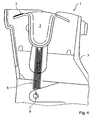
- FIG. 1 shows a side view of the actuator 1 in the locked state. Visible is the bell-shaped vaulted, accessible from above handle 2, which is pivotally mounted in a housing 3 about a rotation axis 4 of a locking position in an unlocked position. From above, the housing 3 is covered with a panel 5, which has an opening 6 for engagement in the handle 2. In addition, at the top of the handle 2 side of the engagement a red marked field 7, the display means is provided, which is visible in the unlocked state through the opening 6 and warns the user visually. In the locked state, the red marked field 7 is covered by the aperture 5. The handle 2 is biased by a tension spring 8 in two stable end positions, which correspond to the locked or unlocked state.
- the tension spring 8 is connected in the embodiment on the one hand above the axis of rotation 4 with the handle 2 and on the other hand below the axis of rotation 4 to a suspension 9 to the housing 3.
- the tension spring 8 is thus stretched when adjusting the handle 2 from one to the other end position, wherein the largest elongation occurs when overlapping with the axis of rotation 4.
- the spring 8 is also biased in the two end positions, for example, to compensate for tolerances and / or to reduce noise.
- FIG. 2 schematically shows the deflection and the lines of force of the spring 8 in the end positions and the center position.
- bistable spring arrangement can in principle also be provided with other structural means, for example by using a lever operatively connected to the deflection lever, on which the tension spring 8 engages.
- other, already inherently bistable springs could be used.
- FIG. 6 Another embodiment of a bistable spring arrangement is shown in FIG. 6 shown.
- Figures 3 - 5 show the display and actuator 1 again in the locked state (end position, see FIG. 3 ), in the unstable Middle position (cf. FIG. 4 ) and in the unlocked state (end position, compare FIG. 5 ).
- FIG. 6 shows a further embodiment of the actuating device according to the invention.
- this actuator comprises a housing 3 with a cover 5, in which a handle 2 is pivotally mounted with a display means 7.
- This handle 2 can take two stable end positions, in which the locking device is in the locked or unlocked position.
- the handle 2 is arranged via a connecting means 15 with a transmission means 14, which in turn is connected via a further connecting means 16, for example a traction cable, with the locking means.
- the transmission means 14 is arranged rotatably about the rotation axis 11.
- On the transmission means 14, a projection 17 is arranged, with which one end 13 of a torsion spring 10 is connected.
- the torsion spring 10 can also be connected directly to the transmission means 14.
- the other end 12 of the torsion spring 10 is connected to the housing 3.
- the torsion spring 10 exerts a torque on the transmission means 14, depending on the position of the end 13 of the spring 10 relative to the line connecting the spring end 12 and the center of the axis of rotation 11, the gear means rotates clockwise or counterclockwise in the locked or unlocked position of the handle.
- this actuator has therefore only two stable end positions.
Landscapes
- Physics & Mathematics (AREA)
- General Physics & Mathematics (AREA)
- Engineering & Computer Science (AREA)
- Automation & Control Theory (AREA)
- Lock And Its Accessories (AREA)
Description
- Die Erfindung betrifft eine Betätigungsvorrichtung mit einer Handhabe zur reversiblen Überführung eines Verriegelungsmechanismus von einem gelösten in einen verriegelten Zustand. Des weiteren betrifft die Erfindung einen Fahrzeugsitz aufweisend die erfindungsgemäße Betätigungsvorrichtung.
- Fahrzeugsitze, insbesondere Rücksitzbänke, weisen oftmals Betätigungsvorrichtungen auf, nach deren Auslösen eine Rückenlehne aus der Gebrauchsstellung in eine Ladestellung verlagerbar ist. Dabei wird beispielsweise eine Verriegelungseinrichtung, z. B. ein Drehfallenschloss, manuell entriegelt und der entriegelte Zustand dem Benutzer von der Betätigungsvorrichtung bis zum erneuten Verriegeln angezeigt. Derartige Betätigungsvorrichtungen sind beispielsweise in der
DE 10 2005 004 276 sowie derDE 101 42 486 B4 offenbart. Eine Betätigungsvorrichtung ohne Anzeigemittel ist beispielsweise aus derDE 10 2004 030 563 A1 bekannt. Die aus dem Stand der Technik bekannten Betätigungsvorrichtungen sind oftmals geräuschanfällig. Insbesondere die Betätigungsvorrichtungen mit einem Anzeigemittel können darüber hinaus leicht beschädigt werden. - Es war deshalb die Aufgabe der vorliegenden Erfindung eine Betätigungsvorrichtung zur Verfügung zu stellen, die die Nachteile des Standes der Technik nicht aufweist.
- Gelöst wird die Aufgabe mit einer Betätigungsvorrichtung mit den Merkmalen der Anspruchs 1.
- Erfindungsgemäß weist die Betätigungsvorrichtung eine in einem Gehäuse angeordnete Handhabe auf. Mit dieser Handhabe wird ein Verriegelungsmechanismus zumindest ausgelöst. Es ist auch möglich, dass die Handhabe den Verriegelungsmechanismus nicht nur auslöst sondern auch betätigt, d.h. die Ver- bzw. Entriegelung tatsächlich auch bewirkt. Vorzugsweise wird die Handhabe durch eine Drehung von der ver- in die entriegelte Stellung und umgekehrt bewegt.
- Weiterhin erfindungsgemäß weist die Betätigungsvorrichtung ein mechanisches Anzeigemittel auf, das dem Benutzer anzeigt, ob der Verriegelungsmechanismus verriegelt ist oder nicht. Mechanisches Anzeigemittel bedeutet im Sinne der Erfindung sind alle Anzeigemittel außer elektrisch betriebenen Anzeigemitteln. Dieses Anzeigemittel ist erfindungsgemäß so an der Handhabe angeordnet, dass zu keinem Zeitpunkt aus dem Gehäuse heraussteht. Dadurch ist das Anzeigemittel vor Beschädigungen geschützt und stellt auch kein Verletzungsrisiko für die Fahrzeuginsassen dar.
- Vorzugsweise ist die Anzeige nur im entriegelten Zustand sichtbar. Die Anzeige kann dann beispielsweise durch ein farbiges, insbesondere rotes Symbol, erfolgen, dass dem Fahrzeuginsassen "Gefahr" signalisiert, weil ein durch den Verriegelungsmechanismus zu verriegelndes Bauteil, beispielsweise die Rückenlehne einer Rückbank nicht verriegelt ist und somit eine potentielle Gefahr darstellt. Im verriegelten Zustand wird die Anzeige dann vorzugsweise durch das Gehäuse verdeckt.
- Vorzugsweise ist das Anzeigemittel auf die Handhabe aufgeklebt.
- Der Gegenstand der vorliegenden Erfindung ist eine Betätigungsvorrichtung mit einer Handhabe zur reversiblen Überführung eines Verriegelungsmechanismus von einem gelösten in einen verriegelten Zustand, wobei die Handhabe in beide Zustände vorgespannt ist.
- Die Betätigungsvorrichtung weist eine in einem Gehäuse angeordnete Handhabe auf. Mit dieser Handhabe wird ein Verriegelungsmechanismus zumindest ausgelöst. Es ist auch möglich, dass die Handhabe den Verriegelungsmechanismus nicht nur auslöst sondern auch betätigt, d.h. die Ver- bzw. Entriegelung tatsächlich auch bewirkt. Vorzugsweise wird die Handhabe durch eine Drehung von der ver- in die entriegelte Stellung und umgekehrt bewegt.
- Die Handhabe ist direkt oder indirekt mit einem Federmittel verbunden. ist, wobei die von dem Federmittel auf die Handhabe ausgeübte Kraft, in deren entriegelnder bzw. verriegelnder Stellung geringer ist als in einer Zwischenstellung. Die Handhabe wird ist demnach immer in eine dieser Stellungen vorgespannt und nimmt selbsttätig keine Zwischenstellung ein.
- Vorzugsweise ist das Federmittel eine Zug-, Blatt oder Torsionsfeder ist.
- Die Betätigungsvorrichtung eignet sich insbesondere als Bauteil eines Fahrzeugsitzes Ein weiterer Gegenstand der vorliegenden Erfindung ist deshalb eine Fahrzeugsitz aufweisend die erfindungsgemäße Betätigungsvorrichtung.
- Vorzugsweise dient die Betätigungsvorrichtung zur Auslösung der Entriegelung und/oder zur Auslösung der Überführung einer Rückenlehne von der einer Gebrauchsstellung in eine Ladestellung.
- Im Folgenden werden die Erfindungen anhand der
Figuren 1 - 6 erläutert. Diese Erläuterungen sind lediglich beispielhaft und schränken den allgemeinen Erfindungsgedanken nicht ein. Die Erläuterungen gelten für alle Erfindungsgegenstände gleichermaßen. - Figur 1
- zeigt erfindungsgemäße Betätigungsvorrichtung.
- Figur 2
- zeigt schematisch die Auslenkung und die dazugehörigen Kräfte der Feder gemäß
Figur 1 . - Figur 3
- zeigt die Handhabe im verriegelten Zustand.
- Figur 4
- zeigt die Handhabe in einer Zwischenstellung.
- Figur 5
- zeigt die Handhabe im entriegelten Zustand.
- Figur 6
- zeigt eine weitere Ausführungsform der erfindungsgemäßen Betätigungsvorrichtung.
-
Figur 1 zeigt eine seitliche Ansicht der Betätigungsvorrichtung 1 im verriegelten Zustand. Sichtbar ist die glockenförmig eingewölbte, von oben zugängliche Handhabe 2, welche in einem Gehäuse 3 um eine Drehachse 4 von einer Verriegelungsstellung in einer Entriegelungsstellung schwenkbar angeordnet ist. Von oben ist das Gehäuse 3 mit einer Blende 5 abgedeckt, welche eine Öffnung 6 zum Eingriff in die Handhabe 2 aufweist. Außerdem ist an der Oberseite der Handhabe 2 seitlich des Eingriffs ein rot markiertes Feld 7, das Anzeigemittel, vorgesehen, welches in entriegeltem Zustand durch die Öffnung 6 hindurch sichtbar ist und den Benutzer visuell warnt. In verriegeltem Zustand ist das rot markierte Feld 7 durch die Blende 5 abgedeckt. Die Handhabe 2 wird durch eine Zugfeder 8 in zwei stabile Endpositionen vorgespannt, welche dem verriegelten bzw. entriegelten Zustand entsprechen. In allen anderen Stellungen ist die Handhabe instabil und wird demnach ohne Fremdeinwirkung immer eine dieser beiden Stellungen einnehmen. Die Zugfeder 8 ist im Ausführungsbeispiel einerseits oberhalb der Drehachse 4 mit der Handhabe 2 und andererseits unterhalb der Drehachse 4 an einer Aufhängung 9 mit dem Gehäuse 3 verbunden. Die Zugfeder 8 wird somit beim Verstellen der Handhabe 2 von einer in die andere Endposition gedehnt, wobei die größte Dehnung bei Überdeckung mit der Drehachse 4 auftritt. Vorzugsweise ist die Feder 8 jedoch auch in den beiden Endpositionen vorgespannt, um beispielsweise Toleranzen auszugleichen und/oder Geräuschentwicklung zu vermindern. -
Figur 2 zeigt schematisch die Auslenkung und die Kraftlinien der Feder 8 in den Endstellungen sowie der Mittelstellung. - Eine derartige bistabile Federanordnung kann grundsätzlich auch mit anderen konstruktiven Mitteln vorgesehen werden, beispielsweise unter Verwendung eines mit der Handhabe wirkverbundenen Umlenkhebels, an welchem die Zugfeder 8 angreift. Ebenso könnten beispielsweise andere, bereits in sich bistabile Federn verwendet werden. Eine weitere Ausführungsform einer bistabilen Federanordnung ist in
Figur 6 dargestellt. - Die weiteren
Figuren 3 - 5 zeigen die Anzeige- und Betätigungsvorrichtung 1 noch einmal in verriegeltem Zustand (Endstellung, vergleicheFigur 3 ), in der instabilen Mittelstellung (vergleicheFigur 4 ) und in entriegeltem Zustand (Endstellung, vergleicheFigur 5 ). -
Figur 6 zeigt eine weitere Ausführungsform der erfindungsgemäßen Betätigungsvorrichtung. Auch diese Betätigungsvorrichtung weist ein Gehäuse 3 mit einer Abdeckung 5 auf, in der eine Handhabe 2 mit einem Anzeigemittel 7 schwenkbar angeordnet ist. Diese Handhabe 2 kann zwei stabile Endstellungen, in der sich die Verriegelungsvorrichtung in der ent- bzw. verriegelten Stellung befindet, einnehmen. Die Handhabe 2 ist über ein Verbindungsmittel 15 mit einem Getriebemittel 14 angeordnet, das wiederrum über ein weiteres Verbindungsmittel 16, beispielsweise ein Zugseil, mit dem Verriegelungsmittel verbunden ist. Das Getriebemittel 14 ist um die Drehachse 11 drehbar angeordnet. An dem Getriebemittel 14 ist ein Ansatz 17 angeordnet, mit dem das eine Ende 13 einer Torsionsfeder 10 verbunden ist. Der Fachmann erkennt, dass die Torsionsfeder 10 auch unmittelbar mit dem Getriebemittel 14 verbunden sein kann. Das andere Ende 12 der Torsionsfeder 10 ist mit dem Gehäuse 3 verbunden. Solange sich die Endpunkte 11, 12 nicht in einer Linie mit dem Mittelpunkt der Drehachse 11 befinden, übt die Torsionsfeder 10 ein Drehmoment auf das Getriebemittel 14 aus, das je nach Stellung des Endes 13 der Feder 10 relativ zu der Verbindungslinie zwischen dem Federende 12 und dem Mittelpunkt der Drehachse 11 das Getriebemittel im oder gegen den Uhrzeigersinn in die ver- oder entriegelnde Stellung der Handhabe verdreht. Auch diese Betätigungsvorrichtung weist demnach lediglich zwei stabile Endstellungen auf. -
- 1
- Anzeige- und Betätigungsvorrichtung
- 2
- Handhabe
- 3
- Gehäuse
- 4
- Drehachse
- 5
- Blende
- 6
- Öffnung
- 7
- Anzeigemittel, Feld (rot markiert)
- 8
- Federmittel, Zugfeder
- 9
- Aufhängung
- 10
- Federmittel, Torsionsfeder
- 11
- Drehachse
- 12
- Lager des Federmittels 10 am Gehäuse 3
- 13
- Lager des Federmittels 10 am Getriebemittel 14
- 14
- Getriebemittel
- 15
- Verbindungsmittel
- 16
- Verbindungsmittel, Zugseil
- 17
- Ansatz
Claims (6)
- Betätigungsvorrichtung mit einem Gehäuse und einer in dem Gehäuse (3, 7) angeordneten Handhabe (2) zur reversiblen Auslösung eines Verriegelungsmechanismus von einem verriegelten in einen gelösten Zustand und die ein mechanisches Anzeigemittel (7) aufweist, wobei dieses Anzeigemittel so an der Handhabe angeordnet ist, dass es nie über das Gehäuse (3, 7) hinaus steht, dadurch gekennzeichnet, dass die Handhabe (2) in beide Zustände vorgespannt ist und sie mit einem Federmittel (8, 10) der Betätigungsvorrichtung direkt oder indirekt verbunden ist, wobei die Kraft, die von dem Federmittel auf die Handhabe ausgeübt wird, in deren verriegelnder und in entriegelnder Stellung geringer ist als in einer Zwischenstellung.
- Betätigungsvorrichtung nach Anspruch 1, dadurch gekennzeichnet, dass die Anzeige nur im entriegelten Zustand sichtbar ist.
- Betätigungsvorrichtung nach einem der voranstehenden Ansprüche, dadurch gekennzeichnet, dass das Anzeigemittel auf die Handhabe aufgeklebt ist.
- Betätigungsvorrichtung nach einem der voranstehenden Ansprüche, dadurch gekennzeichnet, dass das Federmittel eine Zug- oder Torsionsfeder ist.
- Fahrzeugsitz aufweisend eine Betätigungsvorrichtung gemäß einem der voranstehenden Ansprüche.
- Fahrzeugsitz nach Anspruch 5, dadurch gekennzeichnet, dass die Betätigung zur Auslösung der Entriegelung und/oder der Überführung einer Rückenlehne von der einer Gebrauchsstellung in eine Ladestellung dient.
Priority Applications (1)
| Application Number | Priority Date | Filing Date | Title |
|---|---|---|---|
| PL08801736T PL2185991T3 (pl) | 2007-09-04 | 2008-08-28 | Urządzenie wskazujące i uruchamiające oraz siedzenie samochodowe |
Applications Claiming Priority (3)
| Application Number | Priority Date | Filing Date | Title |
|---|---|---|---|
| DE102007041723 | 2007-09-04 | ||
| DE102007060922A DE102007060922A1 (de) | 2007-09-04 | 2007-12-14 | Anzeige- und Betätigungsvorrichtung sowie Fahrzeugsitz |
| PCT/EP2008/007046 WO2009030424A2 (de) | 2007-09-04 | 2008-08-28 | Anzeige- und betätigungsvorrichtung sowie fahrzeugsitz |
Publications (2)
| Publication Number | Publication Date |
|---|---|
| EP2185991A2 EP2185991A2 (de) | 2010-05-19 |
| EP2185991B1 true EP2185991B1 (de) | 2013-12-11 |
Family
ID=40299233
Family Applications (1)
| Application Number | Title | Priority Date | Filing Date |
|---|---|---|---|
| EP08801736.3A Not-in-force EP2185991B1 (de) | 2007-09-04 | 2008-08-28 | Anzeige- und betätigungsvorrichtung sowie fahrzeugsitz |
Country Status (4)
| Country | Link |
|---|---|
| EP (1) | EP2185991B1 (de) |
| DE (1) | DE102007060922A1 (de) |
| PL (1) | PL2185991T3 (de) |
| WO (1) | WO2009030424A2 (de) |
Families Citing this family (3)
| Publication number | Priority date | Publication date | Assignee | Title |
|---|---|---|---|---|
| DE102009056155B4 (de) | 2009-11-25 | 2017-03-09 | Johnson Controls Components Gmbh & Co. Kg | Anzeigevorrichtung |
| DE102012015288B4 (de) | 2012-07-31 | 2014-04-10 | Johnson Controls Gmbh | Entriegelungseinheit für einen Fahrzeugsitz und Fahrzeugsitz |
| DE102014112031A1 (de) * | 2014-08-22 | 2016-02-25 | Witte Automotive Gmbh | Schloss |
Family Cites Families (9)
| Publication number | Priority date | Publication date | Assignee | Title |
|---|---|---|---|---|
| US4592144A (en) * | 1984-06-22 | 1986-06-03 | The Singer Company | Molded scroller saw lock button spring |
| DE3630923A1 (de) * | 1986-09-11 | 1988-03-24 | Opel Adam Ag | Kraftfahrzeug, bei dem zumindest ein sitz eine lendewirbelstuetze hat |
| US4851624A (en) * | 1987-10-05 | 1989-07-25 | Chestnut Benjamin F | Control assembly having panel illumination means |
| FR2742389B1 (fr) * | 1995-12-19 | 1998-02-20 | Faure Bertrand Equipements Sa | Dispositif de verrouillage d'un element mobile d'un siege de vehicule automobile, avec visualisation de verrouillage |
| DE10142486B4 (de) | 2001-08-30 | 2005-12-29 | Witte-Velbert Gmbh & Co. Kg | Verschluss zum Fesseln einer Rückenlehne eines Kraftfahrzeuges an der Karosserie |
| FR2856719B1 (fr) | 2003-06-24 | 2007-12-28 | Faurecia Sieges Automobile | Systeme de verrouillage d'un premier element avec un deuxieme element et siege equipe d'un tel systeme de verrouilage |
| KR100520774B1 (ko) * | 2003-09-30 | 2005-10-12 | 기아자동차주식회사 | 차량의 탈착식 시트 |
| DE102004023401B4 (de) * | 2004-05-12 | 2006-04-13 | Faurecia Autositze Gmbh & Co. Kg | Entriegelungseinrichtung für ein Fondlehnenteil eines Fahrzeuges |
| DE102005004276B4 (de) | 2005-01-28 | 2012-08-16 | Johnson Controls Gmbh | Verriegelungsanzeiger |
-
2007
- 2007-12-14 DE DE102007060922A patent/DE102007060922A1/de not_active Ceased
-
2008
- 2008-08-28 PL PL08801736T patent/PL2185991T3/pl unknown
- 2008-08-28 EP EP08801736.3A patent/EP2185991B1/de not_active Not-in-force
- 2008-08-28 WO PCT/EP2008/007046 patent/WO2009030424A2/de not_active Ceased
Also Published As
| Publication number | Publication date |
|---|---|
| EP2185991A2 (de) | 2010-05-19 |
| WO2009030424A3 (de) | 2009-05-22 |
| DE102007060922A1 (de) | 2009-03-05 |
| PL2185991T3 (pl) | 2014-04-30 |
| WO2009030424A2 (de) | 2009-03-12 |
Similar Documents
| Publication | Publication Date | Title |
|---|---|---|
| EP2766543B1 (de) | Betätigungseinrichtung für ein kraftfahrzeug-türschloss | |
| DE19600524B4 (de) | Schloß, insbesondere für Kraftfahrzeugtüren | |
| EP2766544B1 (de) | Betätigungseinrichtung für ein kraftfahrzeug-türschloss | |
| EP3036389B1 (de) | Kraftfahrzeugtürverschluss | |
| DE102008011545A1 (de) | Kraftfahrzeugtürverschluss | |
| WO2017182027A1 (de) | Kraftfahrzeugtürschloss | |
| DE102020117046B3 (de) | Türgriffanordnung für eine Fahrzeugtür | |
| EP3272977A1 (de) | Kraftfahrzeugschlossanordnung | |
| WO2015172761A1 (de) | Kraftfahrzeugschloss | |
| EP3196393A1 (de) | Innenschwenktüranordnung mit übertotpunktverriegelungseinrichtung | |
| WO2009030424A2 (de) | Anzeige- und betätigungsvorrichtung sowie fahrzeugsitz | |
| EP4133152B1 (de) | Kraftfahrzeug-schloss | |
| EP4416355A1 (de) | Kraftfahrzeug-schloss insbesondere kraftfahrzeug-türschloss | |
| EP3513021B1 (de) | Kraftfahrzeugtürschloss | |
| DE10331497B4 (de) | Kraftfahrzeugtürverschluss | |
| EP3847328A1 (de) | Antriebseinheit für kraftfahrzeugtechnische anwendungen | |
| EP3117057A1 (de) | Kraftfahrzeugtürverschluss | |
| DE102021006216A1 (de) | Kraftfahrzeug-Schloss | |
| DE102008057318A1 (de) | Kraftfahrzeugschloss mit Rückstellung in die Entriegelung | |
| DE102021128439A1 (de) | Kraftfahrzeug-Schloss | |
| DE102019131180A1 (de) | Kraftfahrzeugschloss | |
| EP3768542B1 (de) | Stellantrieb für ein kraftfahrzeug-klappenelement | |
| EP3583282A1 (de) | Kraftfahrzeug | |
| WO2024193752A1 (de) | Kraftfahrzeug | |
| DE102022120976A1 (de) | Kombination aus einem Kraftfahrzeugschloss und einer Kraftfahrzeug-Schloss-Funktionseinheit |
Legal Events
| Date | Code | Title | Description |
|---|---|---|---|
| PUAI | Public reference made under article 153(3) epc to a published international application that has entered the european phase |
Free format text: ORIGINAL CODE: 0009012 |
|
| 17P | Request for examination filed |
Effective date: 20100406 |
|
| AK | Designated contracting states |
Kind code of ref document: A2 Designated state(s): AT BE BG CH CY CZ DE DK EE ES FI FR GB GR HR HU IE IS IT LI LT LU LV MC MT NL NO PL PT RO SE SI SK TR |
|
| AX | Request for extension of the european patent |
Extension state: AL BA MK RS |
|
| 17Q | First examination report despatched |
Effective date: 20110914 |
|
| DAX | Request for extension of the european patent (deleted) | ||
| GRAP | Despatch of communication of intention to grant a patent |
Free format text: ORIGINAL CODE: EPIDOSNIGR1 |
|
| INTG | Intention to grant announced |
Effective date: 20130731 |
|
| GRAS | Grant fee paid |
Free format text: ORIGINAL CODE: EPIDOSNIGR3 |
|
| GRAA | (expected) grant |
Free format text: ORIGINAL CODE: 0009210 |
|
| AK | Designated contracting states |
Kind code of ref document: B1 Designated state(s): AT BE BG CH CY CZ DE DK EE ES FI FR GB GR HR HU IE IS IT LI LT LU LV MC MT NL NO PL PT RO SE SI SK TR |
|
| REG | Reference to a national code |
Ref country code: GB Ref legal event code: FG4D Free format text: NOT ENGLISH |
|
| REG | Reference to a national code |
Ref country code: CH Ref legal event code: EP |
|
| REG | Reference to a national code |
Ref country code: AT Ref legal event code: REF Ref document number: 644890 Country of ref document: AT Kind code of ref document: T Effective date: 20140115 |
|
| REG | Reference to a national code |
Ref country code: IE Ref legal event code: FG4D Free format text: LANGUAGE OF EP DOCUMENT: GERMAN |
|
| REG | Reference to a national code |
Ref country code: DE Ref legal event code: R096 Ref document number: 502008011059 Country of ref document: DE Effective date: 20140206 |
|
| REG | Reference to a national code |
Ref country code: NL Ref legal event code: VDEP Effective date: 20131211 |
|
| PG25 | Lapsed in a contracting state [announced via postgrant information from national office to epo] |
Ref country code: LT Free format text: LAPSE BECAUSE OF FAILURE TO SUBMIT A TRANSLATION OF THE DESCRIPTION OR TO PAY THE FEE WITHIN THE PRESCRIBED TIME-LIMIT Effective date: 20131211 Ref country code: NO Free format text: LAPSE BECAUSE OF FAILURE TO SUBMIT A TRANSLATION OF THE DESCRIPTION OR TO PAY THE FEE WITHIN THE PRESCRIBED TIME-LIMIT Effective date: 20140311 Ref country code: HR Free format text: LAPSE BECAUSE OF FAILURE TO SUBMIT A TRANSLATION OF THE DESCRIPTION OR TO PAY THE FEE WITHIN THE PRESCRIBED TIME-LIMIT Effective date: 20131211 Ref country code: SE Free format text: LAPSE BECAUSE OF FAILURE TO SUBMIT A TRANSLATION OF THE DESCRIPTION OR TO PAY THE FEE WITHIN THE PRESCRIBED TIME-LIMIT Effective date: 20131211 Ref country code: FI Free format text: LAPSE BECAUSE OF FAILURE TO SUBMIT A TRANSLATION OF THE DESCRIPTION OR TO PAY THE FEE WITHIN THE PRESCRIBED TIME-LIMIT Effective date: 20131211 Ref country code: NL Free format text: LAPSE BECAUSE OF FAILURE TO SUBMIT A TRANSLATION OF THE DESCRIPTION OR TO PAY THE FEE WITHIN THE PRESCRIBED TIME-LIMIT Effective date: 20131211 |
|
| REG | Reference to a national code |
Ref country code: PL Ref legal event code: T3 |
|
| REG | Reference to a national code |
Ref country code: LT Ref legal event code: MG4D |
|
| PG25 | Lapsed in a contracting state [announced via postgrant information from national office to epo] |
Ref country code: CY Free format text: LAPSE BECAUSE OF FAILURE TO SUBMIT A TRANSLATION OF THE DESCRIPTION OR TO PAY THE FEE WITHIN THE PRESCRIBED TIME-LIMIT Effective date: 20131211 Ref country code: LV Free format text: LAPSE BECAUSE OF FAILURE TO SUBMIT A TRANSLATION OF THE DESCRIPTION OR TO PAY THE FEE WITHIN THE PRESCRIBED TIME-LIMIT Effective date: 20131211 |
|
| REG | Reference to a national code |
Ref country code: SK Ref legal event code: T3 Ref document number: E 15859 Country of ref document: SK |
|
| PG25 | Lapsed in a contracting state [announced via postgrant information from national office to epo] |
Ref country code: IS Free format text: LAPSE BECAUSE OF FAILURE TO SUBMIT A TRANSLATION OF THE DESCRIPTION OR TO PAY THE FEE WITHIN THE PRESCRIBED TIME-LIMIT Effective date: 20140411 Ref country code: EE Free format text: LAPSE BECAUSE OF FAILURE TO SUBMIT A TRANSLATION OF THE DESCRIPTION OR TO PAY THE FEE WITHIN THE PRESCRIBED TIME-LIMIT Effective date: 20131211 |
|
| PG25 | Lapsed in a contracting state [announced via postgrant information from national office to epo] |
Ref country code: RO Free format text: LAPSE BECAUSE OF FAILURE TO SUBMIT A TRANSLATION OF THE DESCRIPTION OR TO PAY THE FEE WITHIN THE PRESCRIBED TIME-LIMIT Effective date: 20131211 Ref country code: ES Free format text: LAPSE BECAUSE OF FAILURE TO SUBMIT A TRANSLATION OF THE DESCRIPTION OR TO PAY THE FEE WITHIN THE PRESCRIBED TIME-LIMIT Effective date: 20131211 Ref country code: PT Free format text: LAPSE BECAUSE OF FAILURE TO SUBMIT A TRANSLATION OF THE DESCRIPTION OR TO PAY THE FEE WITHIN THE PRESCRIBED TIME-LIMIT Effective date: 20140411 |
|
| REG | Reference to a national code |
Ref country code: DE Ref legal event code: R097 Ref document number: 502008011059 Country of ref document: DE |
|
| PLBE | No opposition filed within time limit |
Free format text: ORIGINAL CODE: 0009261 |
|
| STAA | Information on the status of an ep patent application or granted ep patent |
Free format text: STATUS: NO OPPOSITION FILED WITHIN TIME LIMIT |
|
| PG25 | Lapsed in a contracting state [announced via postgrant information from national office to epo] |
Ref country code: DK Free format text: LAPSE BECAUSE OF FAILURE TO SUBMIT A TRANSLATION OF THE DESCRIPTION OR TO PAY THE FEE WITHIN THE PRESCRIBED TIME-LIMIT Effective date: 20131211 |
|
| 26N | No opposition filed |
Effective date: 20140912 |
|
| REG | Reference to a national code |
Ref country code: DE Ref legal event code: R097 Ref document number: 502008011059 Country of ref document: DE Effective date: 20140912 |
|
| PG25 | Lapsed in a contracting state [announced via postgrant information from national office to epo] |
Ref country code: SI Free format text: LAPSE BECAUSE OF FAILURE TO SUBMIT A TRANSLATION OF THE DESCRIPTION OR TO PAY THE FEE WITHIN THE PRESCRIBED TIME-LIMIT Effective date: 20131211 |
|
| PG25 | Lapsed in a contracting state [announced via postgrant information from national office to epo] |
Ref country code: MC Free format text: LAPSE BECAUSE OF FAILURE TO SUBMIT A TRANSLATION OF THE DESCRIPTION OR TO PAY THE FEE WITHIN THE PRESCRIBED TIME-LIMIT Effective date: 20131211 Ref country code: LU Free format text: LAPSE BECAUSE OF FAILURE TO SUBMIT A TRANSLATION OF THE DESCRIPTION OR TO PAY THE FEE WITHIN THE PRESCRIBED TIME-LIMIT Effective date: 20140828 |
|
| REG | Reference to a national code |
Ref country code: CH Ref legal event code: PL |
|
| GBPC | Gb: european patent ceased through non-payment of renewal fee |
Effective date: 20140828 |
|
| PG25 | Lapsed in a contracting state [announced via postgrant information from national office to epo] |
Ref country code: LI Free format text: LAPSE BECAUSE OF NON-PAYMENT OF DUE FEES Effective date: 20140831 Ref country code: CH Free format text: LAPSE BECAUSE OF NON-PAYMENT OF DUE FEES Effective date: 20140831 Ref country code: BE Free format text: LAPSE BECAUSE OF NON-PAYMENT OF DUE FEES Effective date: 20140831 |
|
| REG | Reference to a national code |
Ref country code: IE Ref legal event code: MM4A |
|
| PG25 | Lapsed in a contracting state [announced via postgrant information from national office to epo] |
Ref country code: GB Free format text: LAPSE BECAUSE OF NON-PAYMENT OF DUE FEES Effective date: 20140828 |
|
| REG | Reference to a national code |
Ref country code: FR Ref legal event code: PLFP Year of fee payment: 8 |
|
| PG25 | Lapsed in a contracting state [announced via postgrant information from national office to epo] |
Ref country code: IE Free format text: LAPSE BECAUSE OF NON-PAYMENT OF DUE FEES Effective date: 20140828 |
|
| REG | Reference to a national code |
Ref country code: AT Ref legal event code: MM01 Ref document number: 644890 Country of ref document: AT Kind code of ref document: T Effective date: 20140828 |
|
| PG25 | Lapsed in a contracting state [announced via postgrant information from national office to epo] |
Ref country code: AT Free format text: LAPSE BECAUSE OF NON-PAYMENT OF DUE FEES Effective date: 20140828 |
|
| PG25 | Lapsed in a contracting state [announced via postgrant information from national office to epo] |
Ref country code: BG Free format text: LAPSE BECAUSE OF FAILURE TO SUBMIT A TRANSLATION OF THE DESCRIPTION OR TO PAY THE FEE WITHIN THE PRESCRIBED TIME-LIMIT Effective date: 20131211 |
|
| PG25 | Lapsed in a contracting state [announced via postgrant information from national office to epo] |
Ref country code: IT Free format text: LAPSE BECAUSE OF FAILURE TO SUBMIT A TRANSLATION OF THE DESCRIPTION OR TO PAY THE FEE WITHIN THE PRESCRIBED TIME-LIMIT Effective date: 20131211 Ref country code: MT Free format text: LAPSE BECAUSE OF FAILURE TO SUBMIT A TRANSLATION OF THE DESCRIPTION OR TO PAY THE FEE WITHIN THE PRESCRIBED TIME-LIMIT Effective date: 20131211 Ref country code: GR Free format text: LAPSE BECAUSE OF FAILURE TO SUBMIT A TRANSLATION OF THE DESCRIPTION OR TO PAY THE FEE WITHIN THE PRESCRIBED TIME-LIMIT Effective date: 20140312 |
|
| PG25 | Lapsed in a contracting state [announced via postgrant information from national office to epo] |
Ref country code: TR Free format text: LAPSE BECAUSE OF FAILURE TO SUBMIT A TRANSLATION OF THE DESCRIPTION OR TO PAY THE FEE WITHIN THE PRESCRIBED TIME-LIMIT Effective date: 20131211 Ref country code: HU Free format text: LAPSE BECAUSE OF FAILURE TO SUBMIT A TRANSLATION OF THE DESCRIPTION OR TO PAY THE FEE WITHIN THE PRESCRIBED TIME-LIMIT; INVALID AB INITIO Effective date: 20080828 |
|
| REG | Reference to a national code |
Ref country code: FR Ref legal event code: PLFP Year of fee payment: 9 |
|
| REG | Reference to a national code |
Ref country code: DE Ref legal event code: R081 Ref document number: 502008011059 Country of ref document: DE Owner name: ADIENT LUXEMBOURG HOLDING S.A.R.L., LU Free format text: FORMER OWNER: JOHNSON CONTROLS GMBH, 51399 BURSCHEID, DE Ref country code: DE Ref legal event code: R081 Ref document number: 502008011059 Country of ref document: DE Owner name: ADIENT LUXEMBOURG HOLDING S.A R.L., LU Free format text: FORMER OWNER: JOHNSON CONTROLS GMBH, 51399 BURSCHEID, DE |
|
| REG | Reference to a national code |
Ref country code: FR Ref legal event code: PLFP Year of fee payment: 10 |
|
| PGFP | Annual fee paid to national office [announced via postgrant information from national office to epo] |
Ref country code: SK Payment date: 20170828 Year of fee payment: 10 Ref country code: CZ Payment date: 20170731 Year of fee payment: 10 Ref country code: FR Payment date: 20170822 Year of fee payment: 10 Ref country code: DE Payment date: 20170831 Year of fee payment: 10 |
|
| PGFP | Annual fee paid to national office [announced via postgrant information from national office to epo] |
Ref country code: PL Payment date: 20170821 Year of fee payment: 10 |
|
| REG | Reference to a national code |
Ref country code: DE Ref legal event code: R081 Ref document number: 502008011059 Country of ref document: DE Owner name: ADIENT LUXEMBOURG HOLDING S.A R.L., LU Free format text: FORMER OWNER: ADIENT LUXEMBOURG HOLDING S.A.R.L., LUXEMBOURG, LU |
|
| REG | Reference to a national code |
Ref country code: DE Ref legal event code: R119 Ref document number: 502008011059 Country of ref document: DE |
|
| PG25 | Lapsed in a contracting state [announced via postgrant information from national office to epo] |
Ref country code: CZ Free format text: LAPSE BECAUSE OF NON-PAYMENT OF DUE FEES Effective date: 20180828 |
|
| REG | Reference to a national code |
Ref country code: SK Ref legal event code: MM4A Ref document number: E 15859 Country of ref document: SK Effective date: 20180828 |
|
| PG25 | Lapsed in a contracting state [announced via postgrant information from national office to epo] |
Ref country code: SK Free format text: LAPSE BECAUSE OF NON-PAYMENT OF DUE FEES Effective date: 20180828 |
|
| PG25 | Lapsed in a contracting state [announced via postgrant information from national office to epo] |
Ref country code: DE Free format text: LAPSE BECAUSE OF NON-PAYMENT OF DUE FEES Effective date: 20190301 |
|
| PG25 | Lapsed in a contracting state [announced via postgrant information from national office to epo] |
Ref country code: FR Free format text: LAPSE BECAUSE OF NON-PAYMENT OF DUE FEES Effective date: 20180831 |
|
| PG25 | Lapsed in a contracting state [announced via postgrant information from national office to epo] |
Ref country code: PL Free format text: LAPSE BECAUSE OF NON-PAYMENT OF DUE FEES Effective date: 20180828 |