EP2185322B1 - Vakuumspannplatte mit einer durch laschen gehaltenen flexiblen arbeitsplatte - Google Patents
Vakuumspannplatte mit einer durch laschen gehaltenen flexiblen arbeitsplatte Download PDFInfo
- Publication number
- EP2185322B1 EP2185322B1 EP08829167A EP08829167A EP2185322B1 EP 2185322 B1 EP2185322 B1 EP 2185322B1 EP 08829167 A EP08829167 A EP 08829167A EP 08829167 A EP08829167 A EP 08829167A EP 2185322 B1 EP2185322 B1 EP 2185322B1
- Authority
- EP
- European Patent Office
- Prior art keywords
- chamber
- plate
- working plate
- working
- chuck according
- Prior art date
- Legal status (The legal status is an assumption and is not a legal conclusion. Google has not performed a legal analysis and makes no representation as to the accuracy of the status listed.)
- Active
Links
Images

Classifications
-
- B—PERFORMING OPERATIONS; TRANSPORTING
- B25—HAND TOOLS; PORTABLE POWER-DRIVEN TOOLS; MANIPULATORS
- B25B—TOOLS OR BENCH DEVICES NOT OTHERWISE PROVIDED FOR, FOR FASTENING, CONNECTING, DISENGAGING, OR HOLDING
- B25B11/00—Work holders not covered by any preceding group in the subclass, e.g. magnetic work holders, vacuum work holders
- B25B11/005—Vacuum work holders
Definitions
- the invention mainly relates to the field of maintaining the workpieces on work tables and in particular the field of vacuum vices.
- the vise must therefore allow the positioning and maintenance of very varied workpieces, which means that on the other hand that the fastening surface of the workpiece in the vice must deliver a constant holding force irrespective of the size of the workpiece and its geometry, and secondly that the workpiece must be located precisely in a direction perpendicular to the surface of the vise.
- Another known constraint for the realization and design of the vises is that the holding operation must be carried out under optimal conditions from the point of view of the time required, either to maneuver the workpiece between two configurations of the vice, or to switch the parts between the already shaped element and an element to be machined, for example on a production line, cutting, drilling, grinding etc ...
- the device responding to the above problems must also satisfy the general constraints of this type of tool namely a satisfactory distribution of the suction pressure on the work surface and optimal sealing of the points not covered by the surface to be maintained, while ensuring a reduced cost of operation of the process.
- the invention therefore aims to solve these major difficulties by proposing a new vice operating by vacuum suction.
- the prior art knows devices for holding parts or objects operating by vacuum suction.
- the suction devices are shutter ball devices for closing or releasing the outlet of the suction ducts of the cells located under a support plate. These devices are complex to implement, with many parts to assemble and difficulties to ensure a reliable seal between the balls and the support plate of the part.
- the membrane When maintaining a part, the underside of which may be flat or non-planar, the membrane may be crushed in several areas of the bearing surface. The stability of the part and its precise positioning in a direction perpendicular to the bearing surface can not be guaranteed.
- said pads are removable and replaceable in case of wear or machining accident.
- the vise according to the invention is connected to a suction device so as to vacuum press a workpiece (1) on a work surface and immobilize it.
- the vise in its general form comprises at least one support plate (3) contiguous to a work plate (2).
- the working surface is represented by the interface between the part to be held and the work plate.
- the support plate (3) comprises a set of chambers, each chamber (4) being in communication with a suction device via a conduit (5), which conduit passes through the support plate (3) and is connected to a device generating a depression, for example a vacuum pump.
- a conduit (5) as described in the invention may have any shape, that is to say of square section, oval or irregular, however the section is preferably circular and therefore the conduit of cylindrical shape.
- the working plate (2) in contact with the part to be held is pierced with orifices (7), which orifices are in communication with underlying chambers (4) connected with the suction device, so that the vacuum generated by the suction device is applied to the working surface, under the part to be maintained, through the suction duct and said holes.
- the working plate is a thin plate (2) of deformable material under the effect of a depression on one side of said thin plate and able to return by elasticity to its initial shape in the absence of pressure difference between both sides of the sheet.
- the plate (2) is a sheet of material made of flexible material, for example a polymer sheet.
- the plate (2) has a thickness of between 0.1 mm and 5 mm, and it is in one or more parts.
- the plate (2) is pierced with orifices (7), the orifices (7) not being axially aligned with the conduits (5) so that an imperforate area (10) of the work plate deforms under the effect of a depression in an underlying chamber (4) when no part to be maintained is disposed at the outlet of the orifice (7) corresponding to this chamber.
- the plate (2) is held at the periphery of each chamber (4) by a plurality of studs (8) of the support plate (3) engaging in perforations (9) of the working plate (2), said studs making contact between the support plate (3) and the part to be held (1), thus ensuring a reference for its positioning.
- the figures show that, when the depression is switched on, the part to be held (1) comes to rest on the studs (8) surrounding a chamber (4) and the zone (10) placed above this chamber does not deforms, while the zones (10) located above the rooms not covered by the part (1) deform and close the ducts (7) located below said zones (10) which deform.
- the deformable sheet acts as a sealing means and sealing around the chamber (s) (4) located (s) in the room.
- the upper surfaces of the pads (8) which are in contact with the underside of the workpiece form a reference surface for precise positioning of the workpiece along an axis Oz perpendicular to the work plate (2).
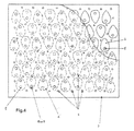
- the preferred and non-limiting form of the chambers (4) represented on the figure 4 allows to increase the number of suction points for an equivalent surface.
- the system operates through two holes: a suction hole which is the perforation (7) of the membrane and a vacuum hole which is the mouth of the duct (5).
- a suction hole which is the perforation (7) of the membrane
- a vacuum hole which is the mouth of the duct (5).
- the depression hole (5) must suck the flexible membrane to seal it tightly around its perimeter.
- This operation is governed by the behavior of the material and in particular by its radius of plating. This radius is governed by a physical law of deformation of the material which is a function of the elasticity properties of the material, its thickness but also the geometry of the chamber and the level of depression.
- the mouth of the duct (5) must (for a vacuum included in 0.95 and 1 bar and a material thickness of 1.5 mm) be placed in the center of a cylinder theoretical free radius of 10 to 14 mm and a height of 0.8 to 1.1 mm, free cylinder which defines the minimum chamber radius to be provided around the mouth of the duct (5).
- the suction chamber forms having the best relationship between the optimization of the suction surface and the simplicity of manufacture are the ovoid forms with an acute end or radius of curvature weaker than the radius of curvature of the other end, recalling shapes in "egg" or "drop of water”.
- the mouth of the duct (5) is placed in the widest part of the chamber while this chamber may be less wide under the face of the orifice (7).
- This distribution makes it possible to reduce the size of each chamber and generates a naturally staggered shape of the chamber on all or part of the support plate (3), which further reduces the distance between two suction points.
- the rooms of the same row are placed side by side with the narrowest part alternately on one side and the other of the direction of the row, and the chambers in a row are offset from those in the next and / or previous row.
- the pads may be removable or dismountable, for example by screwing means.
- This arrangement is particularly advantageous because it allows the adjustment of the height of the pads, especially when the work surface is a left surface, and / or allows the replacement thereof in case of wear or accident of machining.
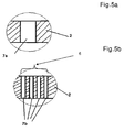
- Two variants may also be provided for an orifice (7), either a single hole (7a) or a surface element (6) perforated with a plurality of perforations or micro-perforations (7b), this variant acting as a flow accelerator and as a filter to stop chips and other machining residues and prevent them from entering the underlying chamber.
- the vice there are no moving parts dependent on gravity which increases the holding possibilities, in particular it allows the use of the vice with a work surface vertically or in an oblique position for example for applications in robotics.
- the part can even be maintained in the event of a vacuum cut.
- the size of the vice, the thickness of the various plates, the power of the depression and the various dimensional parameters can be adjusted within a wide range without departing from the scope of the invention.
- the vise according to the invention can also be used as a pneumatic valve or for object gripping, for example at the end of a robotic arm or on a conveyor chain.
Landscapes
- Engineering & Computer Science (AREA)
- Mechanical Engineering (AREA)
- Jigs For Machine Tools (AREA)
- Manipulator (AREA)
- Auxiliary Devices For Machine Tools (AREA)
- Hooks, Suction Cups, And Attachment By Adhesive Means (AREA)
- Moulds For Moulding Plastics Or The Like (AREA)
- Catching Or Destruction (AREA)
Claims (9)
- Fixierplatte, die mit einer Saugvorrichtung gekoppelt ist, um ein zu haltendes Teil (1) durch Unterdruck auf eine Arbeitsfläche zu drücken und dort festzusetzen, wobei die Fixierplatte eine Arbeitsplatte, die mit dem festzusetzenden Teil in Kontakt ist, und eine Trägerplatte (3) aufweist, die mit der Arbeitsplatte in Kontakt ist, wobei bei der Fixierplatte:- die Arbeitsplatte (2) mit Öffnungen (7) durchsetzt ist, wobei jede Öffnung (7) mit einer darunter liegenden Kammer (4) verbunden ist,- die Trägerplatte (3) eine Anzahl von Kammern (4) aufweist, wobei jede Kammer (4) durch eine Leitung (5) mit der Saugvorrichtung verbunden ist,- in jeder Kammer (4) ein durch Unterdruck versetzbares Schließmittel vorhanden ist, um die Leitung (5) zu schließen, wenn kein zu haltendes Teil (1) an dem Auslass einer Öffnung (7) auf der Arbeitsfläche angeordnet ist,wobei das Schließmittel durch eine nachgiebige und verformbare sowie mit Öffnungen (7) durchsetzte Arbeitsplatte (2) gebildet ist, wobei eine Öffnung (7) nicht axial auf eine Leitung (5) der darunter liegenden Kammer ausgerichtet ist, so dass ein nicht perforierter Bereich (10) der Arbeitsplatte sich unter Einwirkung eines Unterdrucks in einer darunter liegenden Kammer (4) verformt, wenn kein zu haltendes Teil an dem Auslass der dieser Kammer zugeordneten Öffnung (7) angeordnet ist, dadurch gekennzeichnet, dass die Arbeitsplatte (2) am Rand jeder Kammer (4) durch eine Anzahl von Vorsprüngen (8) der Trägerplatte (3) gehalten wird, die mit den Perforierungen (9) der Arbeitsplatte (2) in Eingriff kommen, wobei die Vorsprünge eine Bezugsfläche für die Positionierung des zu haltenden Teils bilden.
- Fixierplatte nach Anspruch 1, dadurch gekennzeichnet, dass die Arbeitsplatte (2) eine perforiertes Polymerfolie ist.
- Fixierplatte nach einem der Ansprüche 1 bis 2, dadurch gekennzeichnet, dass die Vorsprünge (8) abnehmbar sind.
- Fixierplatte nach einem der Ansprüche 1 bis 3, dadurch gekennzeichnet, dass die Kammern (4) jeweils eine ovalartige Gestalt aufweisen.
- Fixierplatte nach Anspruch 4, dadurch gekennzeichnet, dass die Kammern (4) eine ovalartige Gestalt aufweisen, bei der ein Ende weniger breit als das andere ist.
- Fixierplatte nach Anspruch 5, dadurch gekennzeichnet, dass das Saugloch (5) in dem breiteren Bereich der Kammer (4) angeordnet ist.
- Fixierplatte nach einem der Ansprüche 5 bis 6, dadurch gekennzeichnet, dass die Kammern (4) über die ganze oder über einen Teil der Trägerplatte (3) versetzt angeordnet sind.
- Fixierplatte nach einem der Ansprüche 1 bis 7, dadurch gekennzeichnet, dass die Öffnung (7) ein einziges Saugloch (7a) ist.
- Fixierplatte nach einem der Ansprüche 1 bis 7, dadurch gekennzeichnet, dass die Öffnung (7) ein Oberflächenelement (6) ist, das von einer Anzahl von Mikroperforierungen (7b) durchsetzt ist.
Applications Claiming Priority (2)
| Application Number | Priority Date | Filing Date | Title |
|---|---|---|---|
| FR0757232A FR2920329B1 (fr) | 2007-08-29 | 2007-08-29 | Etau maintenant une piece par depression comportant un moyen d'obturation deplacable des conduits d'aspiration |
| PCT/FR2008/051538 WO2009030861A2 (fr) | 2007-08-29 | 2008-08-28 | Etau a depression a plaque de travail souple maintenue par des plots |
Publications (2)
| Publication Number | Publication Date |
|---|---|
| EP2185322A2 EP2185322A2 (de) | 2010-05-19 |
| EP2185322B1 true EP2185322B1 (de) | 2011-04-13 |
Family
ID=39253847
Family Applications (1)
| Application Number | Title | Priority Date | Filing Date |
|---|---|---|---|
| EP08829167A Active EP2185322B1 (de) | 2007-08-29 | 2008-08-28 | Vakuumspannplatte mit einer durch laschen gehaltenen flexiblen arbeitsplatte |
Country Status (8)
| Country | Link |
|---|---|
| US (1) | US8646764B2 (de) |
| EP (1) | EP2185322B1 (de) |
| AT (1) | ATE505299T1 (de) |
| CA (1) | CA2696561C (de) |
| DE (1) | DE602008006208D1 (de) |
| ES (1) | ES2365030T3 (de) |
| FR (1) | FR2920329B1 (de) |
| WO (1) | WO2009030861A2 (de) |
Families Citing this family (5)
| Publication number | Priority date | Publication date | Assignee | Title |
|---|---|---|---|---|
| DE102009044305A1 (de) * | 2009-10-21 | 2011-05-05 | Fooke Gmbh | Verfahren zum Halten und Bearbeiten eines Werkstückes mit Spannplatte, sowie Vorrichtung zum Aussteifen eines Werkstückes mit Spannplatte |
| US8376334B1 (en) * | 2011-10-26 | 2013-02-19 | Swedcord Development AB | Glue free vacuum sealing gasket structure |
| CN105108355B (zh) * | 2015-09-18 | 2017-10-17 | 京东方科技集团股份有限公司 | 承载台、承载装置和激光切割设备 |
| DE102020213943B4 (de) | 2020-11-05 | 2023-09-28 | Volkswagen Aktiengesellschaft | Sauggreifvorrichtung zum Ansaugen eines Objekts |
| JP7485992B2 (ja) * | 2021-01-25 | 2024-05-17 | 日本電信電話株式会社 | Uボルト及び施工方法 |
Family Cites Families (14)
| Publication number | Priority date | Publication date | Assignee | Title |
|---|---|---|---|---|
| US3197170A (en) * | 1963-04-10 | 1965-07-27 | Powers Chemco Inc | Vacuum film support |
| US3335994A (en) * | 1965-04-27 | 1967-08-15 | Cocito Joe Michael | Vacuum holder |
| US3765289A (en) * | 1971-01-15 | 1973-10-16 | Gerber Garment Technology Inc | Vacuum hold-down apparatus |
| US3865359A (en) * | 1972-05-01 | 1975-02-11 | Dbm Industries Ltd | Vacuum apparatus |
| SU650776A1 (ru) * | 1977-05-25 | 1979-03-05 | Предприятие П/Я Р-6816 | Вакуумный стол |
| US4221356A (en) * | 1978-11-09 | 1980-09-09 | Fortune William S | Vacuum operated holding fixture |
| DE3140882A1 (de) * | 1980-10-17 | 1982-05-27 | Dai Nippon Insatsu K.K., Tokyo | Vorrichtung zum befestigen einer offset-druckplatte oder einer aehnlichen platte in ebenem zustand durch unterdruck |
| SE443316B (sv) | 1982-06-07 | 1986-02-24 | Borislav Ilije Simic | Med vakuum arbetande fixeringsanordning |
| US5035409A (en) * | 1989-12-28 | 1991-07-30 | Mpl Precision Limited | Vacuum chuck |
| US5177857A (en) * | 1990-05-17 | 1993-01-12 | Fsk Inc. | Method for holding an object to a surface using valve controlled vacuum force |
| DE9204704U1 (de) * | 1992-04-02 | 1992-06-25 | Kohlmeyer, Peter, 2053 Talkau | Vakuumtisch |
| US5536559A (en) | 1994-11-22 | 1996-07-16 | Wisconsin Alumni Research Foundation | Stress-free mount for imaging mask |
| US6405437B1 (en) * | 1997-09-17 | 2002-06-18 | Arvinmeritor, Inc. | Apparatus and method for encasing an object in a case |
| JP2005003799A (ja) * | 2003-06-10 | 2005-01-06 | Fuji Photo Film Co Ltd | 感光性板状部材吸着機構及び画像記録装置 |
-
2007
- 2007-08-29 FR FR0757232A patent/FR2920329B1/fr not_active Expired - Fee Related
-
2008
- 2008-08-28 CA CA2696561A patent/CA2696561C/fr active Active
- 2008-08-28 DE DE602008006208T patent/DE602008006208D1/de active Active
- 2008-08-28 AT AT08829167T patent/ATE505299T1/de active
- 2008-08-28 WO PCT/FR2008/051538 patent/WO2009030861A2/fr not_active Ceased
- 2008-08-28 US US12/674,657 patent/US8646764B2/en active Active
- 2008-08-28 ES ES08829167T patent/ES2365030T3/es active Active
- 2008-08-28 EP EP08829167A patent/EP2185322B1/de active Active
Also Published As
| Publication number | Publication date |
|---|---|
| US8646764B2 (en) | 2014-02-11 |
| CA2696561A1 (fr) | 2009-03-12 |
| US20110169206A1 (en) | 2011-07-14 |
| FR2920329A1 (fr) | 2009-03-06 |
| WO2009030861A3 (fr) | 2009-05-22 |
| WO2009030861A2 (fr) | 2009-03-12 |
| CA2696561C (fr) | 2015-02-10 |
| FR2920329B1 (fr) | 2009-12-18 |
| DE602008006208D1 (de) | 2011-05-26 |
| ATE505299T1 (de) | 2011-04-15 |
| ES2365030T3 (es) | 2011-09-20 |
| EP2185322A2 (de) | 2010-05-19 |
Similar Documents
| Publication | Publication Date | Title |
|---|---|---|
| CA2696561C (fr) | Etau a depression a plaque de travail souple maintenue par des plots | |
| FR2507931A1 (fr) | Procede de fabrication d'une poulie a gorges multiples en forme de v | |
| CH663558A5 (fr) | Fraise pour usiner les rainures en t. | |
| JP6703536B2 (ja) | 切りくず除去式機械加工用工具および切削インサート | |
| CN101244540A (zh) | 研磨夹具 | |
| FR3078495B1 (fr) | Machine et procede de rivetage | |
| WO2019007064A1 (zh) | 一种金刚石链锯及成型方法 | |
| FR3101266A1 (fr) | Outil de sertissage et procede pour sertir les bords de deux pieces en tole | |
| BE898298A (fr) | Procédé et dispositif pour la fabrication d'un tuyau pourvu de rangées de perforations, dans un dispositif d'estampage. | |
| JP5574947B2 (ja) | 中空構造形成方法及び中空構造体 | |
| CA2449005A1 (fr) | Procede de fabrication de profiles metalliques | |
| FR2894168A1 (fr) | Mandrin de percage | |
| WO2002072300A1 (fr) | Outil de coupe | |
| FR2523884A1 (fr) | Outil d'usinage comportant un siege de plaque coupante et une plaque coupante amovibles | |
| FR2781713A1 (fr) | Procede d'ancrage d'une masse de matiere thermoplastique et piece obtenue par mise en oeuvre de ce procede | |
| EP1858664B1 (de) | Werkzeug und maschine für bearbeitungsvorgänge, die bei inversbetrieb eine gefahr darstellen | |
| FR3005880A1 (fr) | Procede d'emboutissage d'une piece, notamment de carrosserie de vehicule automobile, a prise de pince amelioree | |
| CH716161A1 (fr) | Outil vibrant et ensemble vibrant, système vibratoire, agencement, dispositif avec roulement à billes et diverses machines comprenant un tel outil. | |
| EP3538292A1 (de) | Presswerkzeug für metallblech mit relativ grossen abmessungen, insbesondere für kraftfahrzeuge | |
| JP4892877B2 (ja) | ガイドリフタ | |
| EP2752717A1 (de) | Befestigungsvorrichtung zum Einspannen eines Werkstückrohlings, der zu bearbeiten ist | |
| FR2492286A1 (fr) | Appareil pour la realisation de collets en extremite d'elements tubulaires | |
| FR2643583A1 (fr) | Dispositif de coupe de materiaux durs | |
| FR3054969A1 (fr) | Outil de poinconnage et outil d’emboutissage pour une ebauche de piece pour un vehicule, notamment automobile | |
| EP0051013A1 (de) | Befestigungselement mit kontrollierbarer Lösbarkeit und Werkzeugausrüstung zu dessen Herstellung |
Legal Events
| Date | Code | Title | Description |
|---|---|---|---|
| PUAI | Public reference made under article 153(3) epc to a published international application that has entered the european phase |
Free format text: ORIGINAL CODE: 0009012 |
|
| 17P | Request for examination filed |
Effective date: 20100329 |
|
| AK | Designated contracting states |
Kind code of ref document: A2 Designated state(s): AT BE BG CH CY CZ DE DK EE ES FI FR GB GR HR HU IE IS IT LI LT LU LV MC MT NL NO PL PT RO SE SI SK TR |
|
| AX | Request for extension of the european patent |
Extension state: AL BA MK RS |
|
| RTI1 | Title (correction) |
Free format text: VACUUM CHUCK WITH FLEXIBLE WORKING PLATE MAINTAINED BY LUGS |
|
| GRAP | Despatch of communication of intention to grant a patent |
Free format text: ORIGINAL CODE: EPIDOSNIGR1 |
|
| GRAS | Grant fee paid |
Free format text: ORIGINAL CODE: EPIDOSNIGR3 |
|
| GRAA | (expected) grant |
Free format text: ORIGINAL CODE: 0009210 |
|
| AK | Designated contracting states |
Kind code of ref document: B1 Designated state(s): AT BE BG CH CY CZ DE DK EE ES FI FR GB GR HR HU IE IS IT LI LT LU LV MC MT NL NO PL PT RO SE SI SK TR |
|
| REG | Reference to a national code |
Ref country code: GB Ref legal event code: FG4D Free format text: NOT ENGLISH |
|
| REG | Reference to a national code |
Ref country code: CH Ref legal event code: EP |
|
| REG | Reference to a national code |
Ref country code: IE Ref legal event code: FG4D Free format text: LANGUAGE OF EP DOCUMENT: FRENCH |
|
| REF | Corresponds to: |
Ref document number: 602008006208 Country of ref document: DE Date of ref document: 20110526 Kind code of ref document: P |
|
| REG | Reference to a national code |
Ref country code: DE Ref legal event code: R096 Ref document number: 602008006208 Country of ref document: DE Effective date: 20110526 |
|
| REG | Reference to a national code |
Ref country code: NL Ref legal event code: T3 |
|
| REG | Reference to a national code |
Ref country code: ES Ref legal event code: FG2A Ref document number: 2365030 Country of ref document: ES Kind code of ref document: T3 Effective date: 20110920 |
|
| LTIE | Lt: invalidation of european patent or patent extension |
Effective date: 20110413 |
|
| PG25 | Lapsed in a contracting state [announced via postgrant information from national office to epo] |
Ref country code: SE Free format text: LAPSE BECAUSE OF FAILURE TO SUBMIT A TRANSLATION OF THE DESCRIPTION OR TO PAY THE FEE WITHIN THE PRESCRIBED TIME-LIMIT Effective date: 20110413 Ref country code: PT Free format text: LAPSE BECAUSE OF FAILURE TO SUBMIT A TRANSLATION OF THE DESCRIPTION OR TO PAY THE FEE WITHIN THE PRESCRIBED TIME-LIMIT Effective date: 20110816 Ref country code: NO Free format text: LAPSE BECAUSE OF FAILURE TO SUBMIT A TRANSLATION OF THE DESCRIPTION OR TO PAY THE FEE WITHIN THE PRESCRIBED TIME-LIMIT Effective date: 20110713 Ref country code: LT Free format text: LAPSE BECAUSE OF FAILURE TO SUBMIT A TRANSLATION OF THE DESCRIPTION OR TO PAY THE FEE WITHIN THE PRESCRIBED TIME-LIMIT Effective date: 20110413 Ref country code: HR Free format text: LAPSE BECAUSE OF FAILURE TO SUBMIT A TRANSLATION OF THE DESCRIPTION OR TO PAY THE FEE WITHIN THE PRESCRIBED TIME-LIMIT Effective date: 20110413 |
|
| REG | Reference to a national code |
Ref country code: IE Ref legal event code: FD4D |
|
| PG25 | Lapsed in a contracting state [announced via postgrant information from national office to epo] |
Ref country code: FI Free format text: LAPSE BECAUSE OF FAILURE TO SUBMIT A TRANSLATION OF THE DESCRIPTION OR TO PAY THE FEE WITHIN THE PRESCRIBED TIME-LIMIT Effective date: 20110413 Ref country code: CY Free format text: LAPSE BECAUSE OF FAILURE TO SUBMIT A TRANSLATION OF THE DESCRIPTION OR TO PAY THE FEE WITHIN THE PRESCRIBED TIME-LIMIT Effective date: 20110413 Ref country code: IS Free format text: LAPSE BECAUSE OF FAILURE TO SUBMIT A TRANSLATION OF THE DESCRIPTION OR TO PAY THE FEE WITHIN THE PRESCRIBED TIME-LIMIT Effective date: 20110813 Ref country code: SI Free format text: LAPSE BECAUSE OF FAILURE TO SUBMIT A TRANSLATION OF THE DESCRIPTION OR TO PAY THE FEE WITHIN THE PRESCRIBED TIME-LIMIT Effective date: 20110413 Ref country code: LV Free format text: LAPSE BECAUSE OF FAILURE TO SUBMIT A TRANSLATION OF THE DESCRIPTION OR TO PAY THE FEE WITHIN THE PRESCRIBED TIME-LIMIT Effective date: 20110413 |
|
| PG25 | Lapsed in a contracting state [announced via postgrant information from national office to epo] |
Ref country code: MT Free format text: LAPSE BECAUSE OF FAILURE TO SUBMIT A TRANSLATION OF THE DESCRIPTION OR TO PAY THE FEE WITHIN THE PRESCRIBED TIME-LIMIT Effective date: 20110413 |
|
| PG25 | Lapsed in a contracting state [announced via postgrant information from national office to epo] |
Ref country code: IE Free format text: LAPSE BECAUSE OF FAILURE TO SUBMIT A TRANSLATION OF THE DESCRIPTION OR TO PAY THE FEE WITHIN THE PRESCRIBED TIME-LIMIT Effective date: 20110413 Ref country code: EE Free format text: LAPSE BECAUSE OF FAILURE TO SUBMIT A TRANSLATION OF THE DESCRIPTION OR TO PAY THE FEE WITHIN THE PRESCRIBED TIME-LIMIT Effective date: 20110413 Ref country code: CZ Free format text: LAPSE BECAUSE OF FAILURE TO SUBMIT A TRANSLATION OF THE DESCRIPTION OR TO PAY THE FEE WITHIN THE PRESCRIBED TIME-LIMIT Effective date: 20110413 |
|
| PLBE | No opposition filed within time limit |
Free format text: ORIGINAL CODE: 0009261 |
|
| STAA | Information on the status of an ep patent application or granted ep patent |
Free format text: STATUS: NO OPPOSITION FILED WITHIN TIME LIMIT |
|
| PG25 | Lapsed in a contracting state [announced via postgrant information from national office to epo] |
Ref country code: DK Free format text: LAPSE BECAUSE OF FAILURE TO SUBMIT A TRANSLATION OF THE DESCRIPTION OR TO PAY THE FEE WITHIN THE PRESCRIBED TIME-LIMIT Effective date: 20110413 Ref country code: PL Free format text: LAPSE BECAUSE OF FAILURE TO SUBMIT A TRANSLATION OF THE DESCRIPTION OR TO PAY THE FEE WITHIN THE PRESCRIBED TIME-LIMIT Effective date: 20110413 Ref country code: RO Free format text: LAPSE BECAUSE OF FAILURE TO SUBMIT A TRANSLATION OF THE DESCRIPTION OR TO PAY THE FEE WITHIN THE PRESCRIBED TIME-LIMIT Effective date: 20110413 Ref country code: SK Free format text: LAPSE BECAUSE OF FAILURE TO SUBMIT A TRANSLATION OF THE DESCRIPTION OR TO PAY THE FEE WITHIN THE PRESCRIBED TIME-LIMIT Effective date: 20110413 |
|
| 26N | No opposition filed |
Effective date: 20120116 |
|
| PG25 | Lapsed in a contracting state [announced via postgrant information from national office to epo] |
Ref country code: MC Free format text: LAPSE BECAUSE OF NON-PAYMENT OF DUE FEES Effective date: 20110831 |
|
| REG | Reference to a national code |
Ref country code: CH Ref legal event code: NV Representative=s name: MEYER & KOLLEGEN |
|
| REG | Reference to a national code |
Ref country code: DE Ref legal event code: R097 Ref document number: 602008006208 Country of ref document: DE Effective date: 20120116 |
|
| PG25 | Lapsed in a contracting state [announced via postgrant information from national office to epo] |
Ref country code: BG Free format text: LAPSE BECAUSE OF FAILURE TO SUBMIT A TRANSLATION OF THE DESCRIPTION OR TO PAY THE FEE WITHIN THE PRESCRIBED TIME-LIMIT Effective date: 20110713 |
|
| PG25 | Lapsed in a contracting state [announced via postgrant information from national office to epo] |
Ref country code: TR Free format text: LAPSE BECAUSE OF FAILURE TO SUBMIT A TRANSLATION OF THE DESCRIPTION OR TO PAY THE FEE WITHIN THE PRESCRIBED TIME-LIMIT Effective date: 20110413 |
|
| PG25 | Lapsed in a contracting state [announced via postgrant information from national office to epo] |
Ref country code: HU Free format text: LAPSE BECAUSE OF FAILURE TO SUBMIT A TRANSLATION OF THE DESCRIPTION OR TO PAY THE FEE WITHIN THE PRESCRIBED TIME-LIMIT Effective date: 20110413 |
|
| PG25 | Lapsed in a contracting state [announced via postgrant information from national office to epo] |
Ref country code: GR Free format text: LAPSE BECAUSE OF FAILURE TO SUBMIT A TRANSLATION OF THE DESCRIPTION OR TO PAY THE FEE WITHIN THE PRESCRIBED TIME-LIMIT Effective date: 20110413 |
|
| REG | Reference to a national code |
Ref country code: FR Ref legal event code: PLFP Year of fee payment: 9 |
|
| REG | Reference to a national code |
Ref country code: FR Ref legal event code: PLFP Year of fee payment: 10 |
|
| REG | Reference to a national code |
Ref country code: FR Ref legal event code: PLFP Year of fee payment: 11 |
|
| PGFP | Annual fee paid to national office [announced via postgrant information from national office to epo] |
Ref country code: FR Payment date: 20250617 Year of fee payment: 18 |
|
| PGFP | Annual fee paid to national office [announced via postgrant information from national office to epo] |
Ref country code: LU Payment date: 20250724 Year of fee payment: 18 Ref country code: NL Payment date: 20250724 Year of fee payment: 18 |
|
| PGFP | Annual fee paid to national office [announced via postgrant information from national office to epo] |
Ref country code: ES Payment date: 20250908 Year of fee payment: 18 |
|
| PGFP | Annual fee paid to national office [announced via postgrant information from national office to epo] |
Ref country code: DE Payment date: 20250812 Year of fee payment: 18 |
|
| PGFP | Annual fee paid to national office [announced via postgrant information from national office to epo] |
Ref country code: IT Payment date: 20250808 Year of fee payment: 18 |
|
| PGFP | Annual fee paid to national office [announced via postgrant information from national office to epo] |
Ref country code: BE Payment date: 20250826 Year of fee payment: 18 Ref country code: GB Payment date: 20250826 Year of fee payment: 18 |
|
| PGFP | Annual fee paid to national office [announced via postgrant information from national office to epo] |
Ref country code: AT Payment date: 20250722 Year of fee payment: 18 |
|
| PGFP | Annual fee paid to national office [announced via postgrant information from national office to epo] |
Ref country code: CH Payment date: 20250901 Year of fee payment: 18 |