EP2183330B1 - Conductive scrim embedded structural adhesive films - Google Patents
Conductive scrim embedded structural adhesive films Download PDFInfo
- Publication number
- EP2183330B1 EP2183330B1 EP08798374.8A EP08798374A EP2183330B1 EP 2183330 B1 EP2183330 B1 EP 2183330B1 EP 08798374 A EP08798374 A EP 08798374A EP 2183330 B1 EP2183330 B1 EP 2183330B1
- Authority
- EP
- European Patent Office
- Prior art keywords
- structural adhesive
- adhesive film
- carbon fiber
- repair
- plies
- Prior art date
- Legal status (The legal status is an assumption and is not a legal conclusion. Google has not performed a legal analysis and makes no representation as to the accuracy of the status listed.)
- Active
Links
- 239000002313 adhesive film Substances 0.000 title claims description 142
- 230000008439 repair process Effects 0.000 claims description 169
- 229920000049 Carbon (fiber) Polymers 0.000 claims description 119
- 239000004917 carbon fiber Substances 0.000 claims description 119
- VNWKTOKETHGBQD-UHFFFAOYSA-N methane Chemical compound C VNWKTOKETHGBQD-UHFFFAOYSA-N 0.000 claims description 119
- 238000000034 method Methods 0.000 claims description 94
- 239000010410 layer Substances 0.000 claims description 30
- 239000011347 resin Substances 0.000 claims description 25
- 229920005989 resin Polymers 0.000 claims description 25
- 239000012790 adhesive layer Substances 0.000 claims description 18
- 239000000835 fiber Substances 0.000 claims description 18
- OKTJSMMVPCPJKN-UHFFFAOYSA-N Carbon Chemical compound [C] OKTJSMMVPCPJKN-UHFFFAOYSA-N 0.000 claims description 6
- BASFCYQUMIYNBI-UHFFFAOYSA-N platinum Chemical compound [Pt] BASFCYQUMIYNBI-UHFFFAOYSA-N 0.000 claims description 6
- RYGMFSIKBFXOCR-UHFFFAOYSA-N Copper Chemical compound [Cu] RYGMFSIKBFXOCR-UHFFFAOYSA-N 0.000 claims description 4
- 229910052782 aluminium Inorganic materials 0.000 claims description 4
- XAGFODPZIPBFFR-UHFFFAOYSA-N aluminium Chemical compound [Al] XAGFODPZIPBFFR-UHFFFAOYSA-N 0.000 claims description 4
- 229910052802 copper Inorganic materials 0.000 claims description 4
- 239000010949 copper Substances 0.000 claims description 4
- BQCADISMDOOEFD-UHFFFAOYSA-N Silver Chemical compound [Ag] BQCADISMDOOEFD-UHFFFAOYSA-N 0.000 claims description 3
- 229910002804 graphite Inorganic materials 0.000 claims description 3
- 239000010439 graphite Substances 0.000 claims description 3
- 239000011159 matrix material Substances 0.000 claims description 3
- 229910052697 platinum Inorganic materials 0.000 claims description 3
- 229910052709 silver Inorganic materials 0.000 claims description 3
- 239000004332 silver Substances 0.000 claims description 3
- 239000002131 composite material Substances 0.000 description 28
- 239000004918 carbon fiber reinforced polymer Substances 0.000 description 27
- 230000035515 penetration Effects 0.000 description 15
- 230000008569 process Effects 0.000 description 15
- 238000004519 manufacturing process Methods 0.000 description 14
- 238000010586 diagram Methods 0.000 description 6
- 230000005672 electromagnetic field Effects 0.000 description 6
- 239000004020 conductor Substances 0.000 description 5
- 230000000153 supplemental effect Effects 0.000 description 5
- 238000012360 testing method Methods 0.000 description 5
- 239000000853 adhesive Substances 0.000 description 4
- 230000001070 adhesive effect Effects 0.000 description 4
- 239000002390 adhesive tape Substances 0.000 description 3
- 239000002134 carbon nanofiber Substances 0.000 description 3
- 230000032798 delamination Effects 0.000 description 3
- 239000000446 fuel Substances 0.000 description 3
- 239000000463 material Substances 0.000 description 3
- 239000007769 metal material Substances 0.000 description 3
- 239000002245 particle Substances 0.000 description 3
- 229920000642 polymer Polymers 0.000 description 3
- 206010042255 Struck by lightning Diseases 0.000 description 2
- 229910045601 alloy Inorganic materials 0.000 description 2
- 239000000956 alloy Substances 0.000 description 2
- 230000000712 assembly Effects 0.000 description 2
- 238000000429 assembly Methods 0.000 description 2
- 230000000694 effects Effects 0.000 description 2
- 238000010438 heat treatment Methods 0.000 description 2
- 238000012423 maintenance Methods 0.000 description 2
- 229910052751 metal Inorganic materials 0.000 description 2
- 239000002184 metal Substances 0.000 description 2
- 150000002739 metals Chemical class 0.000 description 2
- 229910052582 BN Inorganic materials 0.000 description 1
- PZNSFCLAULLKQX-UHFFFAOYSA-N Boron nitride Chemical compound N#B PZNSFCLAULLKQX-UHFFFAOYSA-N 0.000 description 1
- 239000000654 additive Substances 0.000 description 1
- 230000000996 additive effect Effects 0.000 description 1
- 239000011230 binding agent Substances 0.000 description 1
- 239000003990 capacitor Substances 0.000 description 1
- 229910052799 carbon Inorganic materials 0.000 description 1
- 239000000969 carrier Substances 0.000 description 1
- 238000005520 cutting process Methods 0.000 description 1
- 238000013461 design Methods 0.000 description 1
- 238000001514 detection method Methods 0.000 description 1
- 230000003467 diminishing effect Effects 0.000 description 1
- 239000006185 dispersion Substances 0.000 description 1
- -1 e.g. Substances 0.000 description 1
- 230000007613 environmental effect Effects 0.000 description 1
- 239000000945 filler Substances 0.000 description 1
- 239000011888 foil Substances 0.000 description 1
- 239000002828 fuel tank Substances 0.000 description 1
- 238000000227 grinding Methods 0.000 description 1
- 238000007689 inspection Methods 0.000 description 1
- 230000010354 integration Effects 0.000 description 1
- 238000003801 milling Methods 0.000 description 1
- 239000000203 mixture Substances 0.000 description 1
- 230000004048 modification Effects 0.000 description 1
- 238000012986 modification Methods 0.000 description 1
- 230000008520 organization Effects 0.000 description 1
- 238000012856 packing Methods 0.000 description 1
- 229920003023 plastic Polymers 0.000 description 1
- 239000004033 plastic Substances 0.000 description 1
- 238000002360 preparation method Methods 0.000 description 1
- 238000009419 refurbishment Methods 0.000 description 1
- 238000010079 rubber tapping Methods 0.000 description 1
- 238000007493 shaping process Methods 0.000 description 1
- 238000011179 visual inspection Methods 0.000 description 1
Images


Classifications
-
- B—PERFORMING OPERATIONS; TRANSPORTING
- B29—WORKING OF PLASTICS; WORKING OF SUBSTANCES IN A PLASTIC STATE IN GENERAL
- B29C—SHAPING OR JOINING OF PLASTICS; SHAPING OF MATERIAL IN A PLASTIC STATE, NOT OTHERWISE PROVIDED FOR; AFTER-TREATMENT OF THE SHAPED PRODUCTS, e.g. REPAIRING
- B29C73/00—Repairing of articles made from plastics or substances in a plastic state, e.g. of articles shaped or produced by using techniques covered by this subclass or subclass B29D
- B29C73/04—Repairing of articles made from plastics or substances in a plastic state, e.g. of articles shaped or produced by using techniques covered by this subclass or subclass B29D using preformed elements
- B29C73/10—Repairing of articles made from plastics or substances in a plastic state, e.g. of articles shaped or produced by using techniques covered by this subclass or subclass B29D using preformed elements using patches sealing on the surface of the article
-
- C—CHEMISTRY; METALLURGY
- C09—DYES; PAINTS; POLISHES; NATURAL RESINS; ADHESIVES; COMPOSITIONS NOT OTHERWISE PROVIDED FOR; APPLICATIONS OF MATERIALS NOT OTHERWISE PROVIDED FOR
- C09J—ADHESIVES; NON-MECHANICAL ASPECTS OF ADHESIVE PROCESSES IN GENERAL; ADHESIVE PROCESSES NOT PROVIDED FOR ELSEWHERE; USE OF MATERIALS AS ADHESIVES
- C09J7/00—Adhesives in the form of films or foils
- C09J7/20—Adhesives in the form of films or foils characterised by their carriers
- C09J7/21—Paper; Textile fabrics
-
- C—CHEMISTRY; METALLURGY
- C09—DYES; PAINTS; POLISHES; NATURAL RESINS; ADHESIVES; COMPOSITIONS NOT OTHERWISE PROVIDED FOR; APPLICATIONS OF MATERIALS NOT OTHERWISE PROVIDED FOR
- C09J—ADHESIVES; NON-MECHANICAL ASPECTS OF ADHESIVE PROCESSES IN GENERAL; ADHESIVE PROCESSES NOT PROVIDED FOR ELSEWHERE; USE OF MATERIALS AS ADHESIVES
- C09J2400/00—Presence of inorganic and organic materials
- C09J2400/20—Presence of organic materials
- C09J2400/26—Presence of textile or fabric
- C09J2400/263—Presence of textile or fabric in the substrate
-
- Y—GENERAL TAGGING OF NEW TECHNOLOGICAL DEVELOPMENTS; GENERAL TAGGING OF CROSS-SECTIONAL TECHNOLOGIES SPANNING OVER SEVERAL SECTIONS OF THE IPC; TECHNICAL SUBJECTS COVERED BY FORMER USPC CROSS-REFERENCE ART COLLECTIONS [XRACs] AND DIGESTS
- Y10—TECHNICAL SUBJECTS COVERED BY FORMER USPC
- Y10T—TECHNICAL SUBJECTS COVERED BY FORMER US CLASSIFICATION
- Y10T156/00—Adhesive bonding and miscellaneous chemical manufacture
- Y10T156/10—Methods of surface bonding and/or assembly therefor
- Y10T156/1089—Methods of surface bonding and/or assembly therefor of discrete laminae to single face of additional lamina
- Y10T156/109—Embedding of laminae within face of additional laminae
-
- Y—GENERAL TAGGING OF NEW TECHNOLOGICAL DEVELOPMENTS; GENERAL TAGGING OF CROSS-SECTIONAL TECHNOLOGIES SPANNING OVER SEVERAL SECTIONS OF THE IPC; TECHNICAL SUBJECTS COVERED BY FORMER USPC CROSS-REFERENCE ART COLLECTIONS [XRACs] AND DIGESTS
- Y10—TECHNICAL SUBJECTS COVERED BY FORMER USPC
- Y10T—TECHNICAL SUBJECTS COVERED BY FORMER US CLASSIFICATION
- Y10T428/00—Stock material or miscellaneous articles
- Y10T428/20—Patched hole or depression
-
- Y—GENERAL TAGGING OF NEW TECHNOLOGICAL DEVELOPMENTS; GENERAL TAGGING OF CROSS-SECTIONAL TECHNOLOGIES SPANNING OVER SEVERAL SECTIONS OF THE IPC; TECHNICAL SUBJECTS COVERED BY FORMER USPC CROSS-REFERENCE ART COLLECTIONS [XRACs] AND DIGESTS
- Y10—TECHNICAL SUBJECTS COVERED BY FORMER USPC
- Y10T—TECHNICAL SUBJECTS COVERED BY FORMER US CLASSIFICATION
- Y10T428/00—Stock material or miscellaneous articles
- Y10T428/28—Web or sheet containing structurally defined element or component and having an adhesive outermost layer
- Y10T428/2804—Next to metal
-
- Y—GENERAL TAGGING OF NEW TECHNOLOGICAL DEVELOPMENTS; GENERAL TAGGING OF CROSS-SECTIONAL TECHNOLOGIES SPANNING OVER SEVERAL SECTIONS OF THE IPC; TECHNICAL SUBJECTS COVERED BY FORMER USPC CROSS-REFERENCE ART COLLECTIONS [XRACs] AND DIGESTS
- Y10—TECHNICAL SUBJECTS COVERED BY FORMER USPC
- Y10T—TECHNICAL SUBJECTS COVERED BY FORMER US CLASSIFICATION
- Y10T428/00—Stock material or miscellaneous articles
- Y10T428/28—Web or sheet containing structurally defined element or component and having an adhesive outermost layer
- Y10T428/2848—Three or more layers
Definitions
- the present disclosure relates to systems and methods for using structural adhesives, and more specifically, to systems and methods for the use of structural adhesive films in repairing carbon fiber reinforced plastic (CFRP) components.
- CFRP carbon fiber reinforced plastic
- Aircraft such as commercial airliners, typically experience some lightning strikes during their service life. In some cases, an aircraft may be struck by lightning as frequently as twice a year. Metallic components on an aircraft may conduct away electrical energy produced by lightning strikes, thus diminishing the force of electromagnetic discharges and minimizing any resultant undesirable effects.
- carbon fiber reinforced components such as carbon fiber reinforce plastic (CFRP) components
- CFRP carbon fiber reinforce plastic
- electrical energy from lighting strikes may be concentrated in a small area, thus creating electrical arcing and thermal energy within carbon fiber reinforced components.
- electrical discharges from lightning strikes generally seek the path of least resistance to ground, electrical current may "move" through the carbon fiber reinforced components.
- carbon fiber reinforced components of an aircraft may be provided with electrical discharge features, (e.g. , external metallic foil strips attached to metallic fasteners) to safely dissipate the electric discharge over a large area.
- electrical discharge features e.g. , external metallic foil strips attached to metallic fasteners
- carbon fiber reinforced components on an aircraft may be covered with conductive meshes (e.g. , aluminum mesh or copper mesh), to form conductive paths along the exterior of the aircraft. These conductive paths form what is known as an electromagnetic field (EMF) shield for the carbon fiber reinforced components.
- EMF electromagnetic field
- a conductive mesh may be incorporated into the laminate plies that make up a carbon fiber reinforced component. Discontinuities to the EMF shield may be undesirable.
- WO-A2-2008/005782 relates to an electroconductive adhesive tape having different adhesion values on both surfaces thereof.
- a method for producing the same is also disclosed.
- the adhesive tape has different adhesion values on both surfaces thereof, elasticity, and electroconductivity along the longitudinal direction as well as the transverse direction.
- the adhesive tape can be used in electronic components, as an electromagnetic wave-shielding tape that permits easy attachment/detachment.
- WO-A2-2006/023860 relates to thermally conductive compositions containing spherical boron nitride filler particles having an average aspect ration of less than 2.0 in a polymer matrix.
- US-A1-2005/0242471 relates to processes for forming shaped articles, in particular bipolar plates for fuel cells, comprising extruding a composite comprising a polymer and at least one additive, and shaping the composite to form an article having a desired shape.
- US-A1-2004/0118579 relates to a flexible heat sink article comprising a base comprising a polymer and a plurality of polymeric protrusions extending away from the base, each protrusion having a major dimension and a minor dimension.
- the base comprises thermally conductive particles
- the protrusions comprise non-spherical thermally conductive particles substantially aligned in the direction of the major dimension within the protrusions.
- JP-A-2004/087824 relates to an electric double layer capacitor having several layers for each electrode comprising activated charcoal, laminated sequentially, with a conductive material interposed between the layers.
- EP-A1-0,583,062 relates to graphitized vapor-grown carbon fibers capable of forming composite materials having the graphitized vapor-grown carbon fibers contained at a high packing density and forming molded members consisting substantially solely of the graphitized vapor-grown carbon fibers.
- Embodiments of systems and methods in accordance with the present disclosure are directed to restoring electrical conductivity during the structural repairs of carbon fiber reinforced components. Many specific details of certain embodiments are set forth in the following description and in FIGURES 1-11 to provide a thorough understanding of such embodiments. The present disclosure may have additional embodiments, or may be practiced without one or more of the details described below.
- embodiments of systems and methods in accordance with the present disclosure restore the electrical conductivity of replacement carbon fiber plies to the surrounding carbon fiber piles of a carbon fiber reinforced component.
- the embodiments of systems and methods may also restore the electrical continuity of a conductive mesh embedded in a carbon fiber reinforced component.
- the systems and methods are achieved via a structural adhesive film that includes an electrically conductive scrim.
- the electrically conductive scrim not only helps to support the adhesive during application and cure, but also provides conductive paths around the repair area to enable electrical connections to the surrounding carbon plies or the conductive mesh.
- these embodiments may advantageously reduce or eliminate electrical arcing between the repair area and the undamaged portion of the carbon fiber reinforced component.
- exemplary method 100 may include specification and design 104 of the aircraft 102 and material procurement 106.
- component and subassembly manufacturing 108 and system integration 110 of the aircraft 102 takes place.
- the aircraft 102 may go through certification and delivery 112 in order to be placed in service 114.
- routine maintenance and service 116 which may also include modification, reconfiguration, refurbishment, and so on).
- a system integrator may include without limitation any number of aircraft manufacturers and major-system subcontractors; a third party may include without limitation any number of venders, subcontractors, and suppliers; and an operator may be an airline, leasing company, military entity, service organization, and so on.
- the aircraft 102 produced by exemplary method 100 may include an airframe 118 with a plurality of systems 120 and an interior 122.
- high-level systems 120 include one or more of a propulsion system 124, an electrical system 126, a hydraulic system 126, and an environmental system 130. Any number of other systems may be included.
- an aerospace example is shown, the principles of the disclosure may be applied to other industries, such as the automotive industry.
- Apparatus and methods embodied herein may be employed during any one or more of the stages of the production and service method 100.
- components or subassemblies corresponding to production process 108 may be fabricated or manufactured in a manner similar to components or subassemblies produced while the aircraft 102 is in service.
- one or more apparatus embodiments, method embodiments, or a combination thereof may be utilized during the production stages 108 and 110, for example, by substantially expediting assembly of or reducing the cost of an aircraft 102.
- apparatus embodiments, method embodiments, or a combination thereof may be utilized while the aircraft 102 is in service, for example and without limitation, to maintenance and service 116.
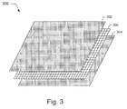
- FIGURE 3 is an isometric view illustrating structural adhesive films that include electrically conductive scrims, in accordance with embodiments of the present disclosure.
- FIGURE 3 depicts an exemplary structural adhesive film 300.
- the exemplary structural adhesive film 300 includes a first resin adhesive layer 302 and a second resin adhesive layer 304.
- the first resin adhesive layer 302 and the second resin adhesive layer 304 are configured to bond to carbon fiber laminate plies, such as carbon-fiber reinforced plastic (CFRP) plies.
- CFRP carbon-fiber reinforced plastic
- each of the first resin adhesive layer 302 and the second adhesive layer 304 may include one of a prepreg film or paste.
- An electrically conductive scrim layer 306 is disposed between the first resin adhesive layer 302 and the second resin adhesive layer 304. According to various implementations, the electrically conductive scrim layer 306 may be embed into and adhere to both the first resin adhesive
- the electrically conductive scrim layer 306 may be pressed into both the first resin layer 102 and the second resin layer 304 so that it is infused with resin from both resin layers.
- the electrically conductive scrim layer 306 is configured to provide continuous electrical conductivity throughout the exemplary structural adhesive film 300, and may also serve as a binding matrix that gives form to the film.
- the electrically conductive scrim layer 306 may be in any configuration, such as without limitation, of a mesh, knitted mat, or random fiber mat comprised of intersecting strands of conductive fibers. Collectively, these various mesh and mats are also known as carriers.
- the conductive fibers may include both metallic and non-metallic materials.
- the conductive fibers may be made of typical ductile conductors (e.g., copper, aluminum, platinum, silver, or alloys that include such metals).
- the conductive fibers may also be manufactured from non-metallic conductors such as graphite.
- the electrically conductive scrim layer 306 may be in any configuration, such as and without limitation, a mesh, knitted mat, or random fiber mat comprised of intersecting strands of conductive fibers.
- the conductive fibers may include both metallic and non-metallic materials.
- the conductive fibers may be made of typical ductile conductors ( e.g. , copper, aluminum, platinum, silver, or alloys that include such metals).
- the conductive fibers may also be manufactured from non-metallic conductors such as graphite.
- FIGURE 3 shows an embodiment of an electrically conductive scrim embedded structural adhesive film
- additional embodiments may include a plurality of electrically conductive scrim layers.
- FIGURES 4a and 4b are side views of exemplary techniques 400 and 414 for repairing composite laminate components using an exemplary structural adhesive film described in FIGURE 3 .
- FIGURE 4a illustrates an exemplary technique 400 for the repair of non-through penetration of a carbon fiber reinforced component.
- FIGURE 4b illustrates an exemplary technique 414 for the repair of through-penetration of a carbon fiber reinforced component.
- Exemplary repair techniques 400 and 414 may be referred to herein as a "scarf" repair technique.
- Repair technique 400 may be performed on a carbon fiber reinforced component 402, which may be a carbon fiber reinforced plastic (CFRP) component.
- the carbon fiber reinforced component 402 may include multiple plies 404 of carbon fiber laminates.
- carbon fiber reinforced component 402 may include a non-through penetration repair area 406, (e.g., dents, cracks, fissures, etc.).
- the repair area 406 may be prepared for repair by the removal of portions from successive layers of plies to form a tapered recess 408.
- the corners of the recess 408 may also be rounded off.
- the removal of portions from successive layers to form the recess 408 may be accomplished using any suitable manufacturing tool or process, such as a high-speed grinder.
- the tapering of the recess 408 may be adjusted as a function of the load experienced by the carbon fiber reinforced component 402. For instance, if the carbon fiber reinforced component 402 experiences a light load, a steep taper may be used. However, if the carbon fiber reinforced component 402 is subjected to a heavy load, a more gradual taper grade may be utilized.
- the repair technique 400 includes the placement of an electrically conductive scrim embedded structural adhesive film 410 into the recess 408.
- the structural adhesive film 410 may be the structural adhesive film described above and shown in FIGURE 3 .
- One or more plies of replacement laminates 412 may then be placed over the structural adhesive film 410 to restore the repair area 408.
- the electrically conductive scrim embedded structural adhesive film 410 is positioned between the plies of the tapered recess 408 and one or more plies of the replacement laminate 412 such that sufficient electrical contact is established between the two assemblages of plies.
- This electrical contact may act to ensure that any lightning discharges directed to the replacement laminates 412 is adequately conducted away into the surrounding plies 404 of carbon fiber laminates.
- the electrical discharge from the lightning may be dispersed from the non-through penetration repair area 406 to a bigger area to minimize its impact.
- the electrical discharge may also travel to one or more electrical discharge features.
- FIGURE 4b illustrates an exemplary technique 414 for the repair of through-penetration of a carbon fiber reinforced component.
- Repair technique 414 may be performed on a carbon fiber reinforced component 416, which may be a carbon fiber reinforced plastic (CFRP) component.
- the carbon fiber reinforced component 416 may include multiple plies 418 of carbon fiber laminates.
- carbon fiber reinforced component 416 may include a through-penetration repair area 420, (e.g., a puncture that completely penetrates carbon fiber reinforced component 416).
- the repair area 420 may be prepared for repair in substantially the same way as the repair area 406 to form a tapered recess 422.
- the repair technique 414 includes the placement of one or more backup plies 424 on the inner side of through-penetration repair area 420.
- a conductive scrim embedded structural adhesive film 426 is placed into the tapered recess 422.
- the structural adhesive film 426 may be the structural adhesive film described above and shown in FIGURE 3 .
- One or more plies of replacement laminates 428 may then be placed over the structural adhesive film 426 to restore the repair area 420.
- the electrically conductive scrim embedded structural adhesive film 426 is positioned between the plies of the tapered recess 422, the one or more backup plies 424, and the one or more plies of the replacement laminate 428 such that sufficient electrical contact is established between the assemblages of plies.
- This electrical contact may act to ensure that any lightning discharges directed to the replacement laminates 428 is adequately conducted away into the surrounding plies 418 of carbon fiber laminates.
- the electrical discharge from the lightning may be dispersed from the through-penetration repair area 420 to a bigger area to minimize its impact.
- the electrical discharge may also travel to one or more electrical discharge features.
- FIGURE 5a and 5b are side views of exemplary techniques 500 and 520 for repairing mesh-covered composite laminate components using an exemplary structural adhesive film described in FIGURE 3 .
- FIGURE 5a illustrates an exemplary technique 500 for the repair of non-through penetration of a mesh-covered carbon fiber reinforced component.
- FIGURE 5b illustrates an exemplary technique 520 for the repair of through-penetration of a carbon fiber reinforced component.
- Repair technique 500 may be performed on a carbon fiber reinforced component 502, which may be a carbon fiber reinforced plastic (CFRP) component.
- the carbon fiber reinforced component 502 may include multiple plies 504 of carbon fiber laminates.
- the carbon fiber reinforced component 502 may also include a conductive mesh 506, which may be positioned on the surface of the plies 504.
- the conductive mesh 506 may be electrically coupled to a suitable ground for dissipating electrical discharges away from the composite laminate assembly.
- carbon fiber reinforced component 502 may include a non-through penetration repair area 508, (e.g., dents, cracks, fissures, etc.).
- the repair area 508 may be prepared for repair by the removal of portions from successive layers of plies to form a tapered recess 510.
- the corners of the recess 510 may also be rounded off.
- the removal of portions from successive layers to form the recess 510 may be accomplished using any suitable manufacturing tool or process, such as a high-speed grinder.
- the tapering of the recess 510 may be adjusted as a function of the load experienced by the carbon fiber reinforced component 502. For instance, if the carbon fiber reinforced component 502 experiences a light load, a steep taper may be used. However, if the carbon fiber reinforced component 502 is subjected to a heavy load, a more gradual taper grade may be utilized.
- the repair technique 500 includes the placement of a structural adhesive film 512 into the recess 510.
- the structural adhesive film 512 is an electrically conductive structural adhesive film, such as those described above and shown in FIGURE 3 .
- One or more plies of replacement laminates 514 may then be placed over the adhesive film 512 to at least partially restore the repair area 508.
- an electrically conductive scrim embedded structural adhesive film 516 is placed on top of the one or more plies of replacement laminates 514.
- the structural adhesive film 516 may be the structural adhesive film described above and shown in FIGURE 3 .
- the structural adhesive film 516 may be positioned so that at least a portion of its embedded electrically conductive scrim makes electrical contact with the conductive mesh 506.
- sufficient electrical contact between the conductive scrim the conductive mesh 506 may be formed in such a way as to enable the dispersal of a lightning electrical discharge from the non-thorough penetration repair area 508.
- one or more top plies of replacement laminates 518 may be adhered to the structural adhesive film 516 to complete the repair.
- additional plies of laminates may be further placed on the replacement laminates 518 to provide additional strength to the repair.
- the structural adhesive film 516 is configured to conduct electrical discharges away from the repaired area 508, provided sufficient electrical conductivity is established to the conductive mesh 506 that is disposed on the surface of the carbon fiber reinforced component 502.
- FIGURE 5b illustrates an exemplary technique 520 for the repair of through-penetration of a carbon fiber reinforced component.
- Repair technique 520 may be performed on a carbon fiber reinforced component 522, which may be a carbon fiber reinforced plastic (CFRP) component.
- the carbon fiber reinforced component 522 may include multiple plies 524 of carbon fiber laminates.
- the carbon fiber reinforced component 502 may also include a conductive mesh 526, which positioned on the surface of the plies 524.
- the conductive mesh 526 may be electrically coupled to a suitable ground for dissipating electrical discharges away from the composite laminate assembly.
- carbon fiber reinforced component 526 may include a through-penetration repair area 528, (e.g., a puncture that completely penetrates carbon fiber reinforced component 522).
- the repair area 528 may be prepared for repair in substantially the same way as the repair area 508 to form a tapered recess 530.
- the repair technique 520 includes the placement of one or more backup plies 532 on the inner side of through-penetration repair area 528.
- a structural adhesive film 534 is positioned into the tapered recess 530.
- the structural adhesive film 534 may be configured to bind to the one or more backup plies 532.
- the structural adhesive film 534 is an electrically conductive structural adhesive film described above and shown in FIGURE 3 .
- One or more plies of replacement laminates 536 may then be placed over the adhesive film 534 to at least partially restore the through-penetration repair area 528.
- an electrically conductive scrim embedded structural adhesive film 538 is placed on top of the one or more plies of replacement laminates 536.
- the structural adhesive film 538 may be the structural adhesive film described above and shown in FIGURE 3 .
- the structural adhesive film 538 may be positioned so that at least a portion of its embedded conductive scrim makes electrical contact with the conductive mesh 526.
- sufficient electrical contact between the electrically conductive scrim and the conductive mesh 526 may be formed in such a way as to enable the dispersal of a lightning electrical discharge from the through-penetration repair area 528.
- one or more top plies of replacement laminates 540 may be adhered to the structural adhesive film 538 to complete the repair.
- additional plies of laminates may be further placed on the replacement laminates 540 to provide additional strength to the repair.
- the structural adhesive film 538 is configured to conduct electrical discharges away from the repair, provided sufficient electrical conductivity is established in the conductive mesh 526 that is disposed on the surface of the carbon fiber reinforced component 522.
- FIGURES 6a and 6b are side views of exemplary techniques 600 and 614 for repairing composite laminate components using an exemplary structural adhesive film described in FIGURE 3 .
- FIGURE 6a illustrates an exemplary technique 600 for the repair of non-through penetration to a carbon fiber reinforced component.
- FIGURE 6b illustrates an exemplary technique 614 for the repair of through-penetration to a carbon fiber reinforced component.
- Exemplary repair techniques 600 and 620 may be referred to herein as a "step" repair technique.
- Repair technique 600 may be performed on a carbon fiber reinforced component 602, which may be a carbon fiber reinforced plastic (CFRP) component.
- the carbon fiber reinforced component 602 may include multiple plies 604 of carbon fiber laminates.
- carbon fiber reinforced component 602 may include a non-through penetration repair area 606, (e.g., dents, cracks, fissures, etc.) that is prepared for step repair.
- the repair area 606 may be prepared for repair by the removal of portions from successive layers of plies to form a stepped recess 608.
- the corners of the recess 608 may also be rounded off to remove burrs.
- the stepped recess 608 may be achieved by removing material from each ply in a step-like fashion via any suitable manufacturing tool or process, such as, without limitations, routering cutting or milling.
- the repair technique 600 includes the placement of a plurality of electrically conductive scrim embedded structural adhesive films 610 into the stepped recess 608.
- the structural adhesive films 610 may be the structural adhesive films described above with respect to FIGURE 3 .
- an electrically conductive scrim embedded structural adhesive film 610 may be positioned so that at least a portion of the embedded electrically conductive scrim makes electrical contact with the embedded electrically conductive scrim of an adjoining structural adhesive film 610.
- electrically conductive scrim embedded structural adhesive film 610a may be disposed so as to make electrical contact with portion 610b.
- portion 610b may be disposed to make electrical contact with portion 610c, and so on and so forth for 610d and 610e.
- one or more plies of replacement laminates 612 may be alternatively inter-dispersed over each layer of structural adhesive film 610 to restore the repair area 606.
- the electrical contacts between the adhesive films 610a-610e may act to ensure that any lightning discharges directed to the replacement laminates 612 is adequately conducted away into the surrounding plies 604 of carbon fiber laminates.
- the electrical discharge from the lightning may be dispersed from the non-through penetration repair area 606 to a bigger area to minimize its impact.
- the electrical discharge may also travel to one or more electrical discharge features.
- FIGURE 6b illustrates an exemplary technique 614 for the repair of through-penetration of a carbon fiber reinforced component.
- Repair technique 614 may be performed on a carbon fiber reinforced component 616, which may be a carbon fiber reinforced plastic (CFRP) component.
- the carbon fiber reinforced component 616 may include multiple plies 618 of carbon fiber laminates.
- carbon fiber reinforced component 616 may include a through-penetration repair area 620, (e.g., a puncture that completely penetrates carbon fiber reinforced component 616).
- the repair area 620 may be prepared for repair in substantially the same way as the repair area 606 to form a tapered recess 622.
- the repair technique 614 includes the placement of one or more backup plies 624 on the inner side of through-penetration repair area 620.
- An electrically conductive scrim embedded structural adhesive film, such as adhesive film 626a, may be positioned into the tapered recess 622 so as to contact one of the backup plies 624.
- an electrically conductive scrim embedded structural adhesive film 626 may be positioned so that at least a portion of the embedded electrically conductive scrim makes electrical contact with the embedded electrically conductive scrim of an adjoining structural adhesive film 626.
- electrically conductive 626a may be disposed so as to make electrical contact with portion 626b.
- portion 626b may be disposed to make electrical contact with portion 626c, and so on and so forth for 626d and 626e.
- one or more plies of replacement laminates 628 may be alternatively inter-dispersed over each layer of structural adhesive film 626 to restore the repair area 620.
- the electrical contacts between the adhesive films 626a-626e may act to ensure that any lightning discharges directed to the replacement laminates 628 is adequately conducted away into the surrounding plies 618 of carbon fiber laminates.
- the electrical discharge from the lightning may be dispersed from the non-through penetration repair area 620 to a bigger area to minimize its impact.
- the electrical discharge may also travel to one or more electrical discharge features.
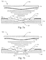
- FIGURE 7a and 7b are side views of exemplary techniques 700 and 720 for repairing mesh-covered composite laminate components using an exemplary structural adhesive film described in FIGURE 3 .
- FIGURE 7a illustrates an exemplary technique 700 for the repair of non-through penetration of a mesh-covered carbon fiber reinforced component.
- FIGURE 7b illustrates an exemplary technique 720 for the repair of through-penetration to a carbon fiber reinforced component.
- Repair technique 700 may be performed on a carbon fiber reinforced component 702, which may be a carbon fiber reinforced plastic (CFRP) component.
- the carbon fiber reinforced component 702 may include multiple plies 704 of carbon fiber laminates.
- the carbon fiber reinforced component 702 may also include a conductive mesh 706, which positioned on the surface of the plies 704.
- the conductive mesh 706 may be electrically coupled to a suitable ground for dissipating electrical discharges away from the composite laminate assembly.
- carbon fiber reinforced component 702 may include a non-through penetration repair area 708, (e.g. , dents, cracks, fissures, etc.).
- the repair area 708 may be prepared for repair by the removal of portions from successive layers of plies to form a stepped recess 710.
- the corners of the stepped recess 710 may also be rounded off to remove burrs.
- the removal of portions from successive layers to form the stepped recess 710 may be accomplished using any suitable manufacturing tool or process, such as, without limitation, a high-speed grinder.
- the length of each step in the recess 710 may be adjusted as a function of the load experienced by the carbon fiber reinforced component 702. For instance, if the carbon fiber reinforced component 702 experiences a light load, a shorter step may be used. However, if the carbon fiber reinforced component 702 is subjected to a heavy load, a longer step may be utilized.
- the repair technique 700 includes the placement of structural adhesive films 712 into the recess 710.
- the structural adhesive films 712 are the electrically conductive structural adhesive film described above and shown in FIGURE 3 . Further, an electrically conductive scrim embedded structural adhesive film 712 may be positioned on each "step" of the recess 710.
- Each of the structural adhesive films 712 may be positioned so that at least a portion of the embedded electrically conductive scrim makes electrical contact with the embedded electrically conductive scrim of an adjoining structural adhesive film 712.
- electrically conductive scrim embedded structural adhesive film 712a may be disposed so as to make electrical contact with portion 712b.
- portion 712b may be disposed to make electrical contact with portion 712c, and so on and so forth.
- one or more plies of replacement laminates 714 may be inter-dispersed over each layer of structural adhesive film 712 to restore the repair area 706.
- the electrical contacts between the adhesive films 712a-712d may act to ensure that any lightning discharges directed to the replacement laminates 714 is adequately conducted away into the surrounding plies 704 of carbon fiber laminates.
- the electrical discharge from the lightning may be dispersed from the non-through penetration repair area 708 to a bigger area to minimize its impact.
- an electrically conductive scrim embedded structural adhesive film 716 is placed on top of the one or more plies of replacement laminates 714.
- the structural adhesive film 716 may be the structural adhesive film described above and shown in FIGURE 3 .
- the structural adhesive film 716 may be positioned so that at least a portion of its embedded conductive scrim makes electrical contact with the conductive mesh 706.
- sufficient electrical contact between the electrically conductive scrim the conductive mesh 706 may be formed in such a way as to enable the dispersal of a lightning electrical discharge from the non-through penetration repair area 708.
- one or more top plies of replacement laminates 718 may be adhered to the structural adhesive film 716 to complete the repair.
- additional plies of laminates may be further placed on the replacement laminates 718 to provide additional strength to the repair.
- the structural adhesive film 716 is configured to conduct electrical discharges away from the repair, provided sufficient electrical conductivity is established to the conductive mesh 706 that is disposed on the surface of the carbon fiber reinforced component 702.
- FIGURE 7b illustrates an exemplary technique 720 for the repair of through-penetration of a carbon fiber reinforced component.
- Repair technique 720 may be performed on a carbon fiber reinforced component 722, which may be a carbon fiber reinforced plastic (CFRP) component.
- the carbon fiber reinforced component 722 may include multiple plies 724 of carbon fiber laminates.
- the carbon fiber reinforced component 722 may also include a conductive mesh 726, which may be positioned on the surface of the plies 724.
- the conductive mesh 726 may be electrically coupled to a suitable ground for dissipating electrical discharges away from the composite laminate assembly.
- carbon fiber reinforced component 720 may include a through-penetration repair area 728, (e.g., a puncture that completely penetrates carbon fiber reinforced component 722).
- the repair area 728 may be prepared for repair in substantially the same way as the repair area 728 to form a stepped recess 730.
- the repair technique 720 includes the placement of one or more backup plies 732 on the inner side of through-penetration repair area 728.
- a structural adhesive film 734a may be positioned into the stepped recess 730 so as to contact one of the backup plies 732.
- additional structural adhesive films 734 such as 734b-734e, may be placed.
- the structural adhesive films 734 are the electrically conductive structural adhesive film described above and shown in FIGURE 3 .
- Each of the structural adhesive films 734 may be positioned so that at least a portion of the embedded electrically conductive scrim makes electrical contact with the embedded electrically conductive scrim of an adjoining structural adhesive film 734.
- electrically conductive scrim embedded structural adhesive film 734a may be disposed so as to make electrical contact with portion 734b.
- portion 734b may be disposed to make electrical contact with portion 734c, and so on and so forth.
- one or more plies of replacement laminates 736 may be alternatively inter-dispersed over each layer of structural adhesive film 734 to restore the repair area 728.
- the electrical contacts between the adhesive films 734a-734b may act to ensure that any lightning discharges directed to the replacement laminates 736 is adequately conducted away into the surrounding plies 724 of carbon fiber laminates.
- the electrical discharge from the lightning may be dispersed from the non-through penetration repair area 728 to a bigger area to minimize its impact.
- an electrically conductive scrim embedded structural adhesive film 738 is placed on top of the one or more plies of replacement laminates 736.
- the structural adhesive film 738 may be the structural adhesive film described above and shown in FIGURE 3 .
- the structural adhesive film 738 may be positioned so that at least a portion of its embedded electrically conductive scrim makes electrical contact with the conductive mesh 726.
- one or more top plies of replacement laminates 740 may be adhered to the structural adhesive film 738 to complete the repair.
- additional plies of laminates (not shown) may be further placed on the replacement laminates 740 to provide additional strength to the repair.
- the structural adhesive film 738 is configured to conduct electrical discharges away from the repair, provided sufficient electrical conductivity is established to the conductive mesh 726 that is disposed on the surface of the carbon fiber reinforced component 722.
- FIGURE 8a is a side view of an exemplary blister patch technique for repairing composite laminate components using an exemplary structural adhesive film described in FIGURE 3 .
- blister patch repairs are interim repairs that do not involve the removal of material from the damaged area. Rather, a patch that includes one or more repair laminate plies is affixed to the surface of the damaged area with an adhesive film layer.
- Repair technique 800 may be performed on a carbon fiber reinforced component 802, which may be a carbon fiber reinforced plastic (CFRP) component.
- the carbon fiber reinforced component 802 may include multiple plies 804 of carbon fiber laminates.
- CFRP carbon fiber reinforced plastic
- FIGURE 8a carbon fiber reinforced component 802 may include a repair area 806.
- repair area 806 may have suffered some cracks or fissures.
- An electrically conductive scrim embedded structural adhesive film 808 is placed on top of the repair area 806 (e.g., cracks, fissures, etc.).
- the structural adhesive film 808 may be the structural adhesive film described above and shown in FIGURE 3 .
- One or more plies of supplemental laminates 810 may then be placed over the structural adhesive film 808 to cover up repair area 806.
- the electrically conductive scrim embedded structural adhesive film 808 is positioned between the multiple plies 804 and one or more plies of the supplemental laminates 810 such that sufficient electrical contact is established between the two assemblages of plies. This electrical contact may act to ensure that any lightning discharges directed to the supplemental laminates 810 is adequately conducted away into the multiple plies 804. Thus, the electrical discharge from the lightning may be dispersed from the supplemental plies 810 to a bigger area.
- FIGURE 8b is a side view of an exemplary blister patch technique for repairing mesh-covered composite laminate components using an exemplary structural adhesive film described in FIGURE 3 .
- Repair technique 812 may be performed on a carbon fiber reinforced component 814, which may be a carbon fiber reinforced plastic (CFRP) component.
- the carbon fiber reinforced component 814 may include multiple plies 816 of carbon fiber laminates.
- CFRP carbon fiber reinforced plastic
- carbon fiber reinforced component 812 may include a repair area 818.
- repair area 818 may have suffered some surface or shallow inconsistencies.
- the carbon fiber reinforced component 814 may be at least partially covered with a conductive mesh 820 that is electrically coupled to a suitable ground for dissipating electrical discharges away from the composite laminate assembly.
- An electrically conductive scrim embedded structural adhesive film 822 is placed on top of the repair area 818 (e.g., cracks, fissures, etc.).
- the structural adhesive film 822 may be the structural adhesive film described above and shown in FIGURE 3 .
- One or more plies of supplemental laminates 824 may then be placed over the structural adhesive film 822 to cover up repair area 818.
- the electrically conductive scrim embedded structural adhesive film 822 may be positioned so that at least a portion of its embedded conductive scrim makes electrical contact with the conductive mesh to enable the dispersal of a lightning electrical discharge from the repair area 818.
- the structural adhesive film may be used in other repair techniques where non-conductive structural adhesive films are used.
- the conductive scrim embedded structural adhesive film may also be used for the repair of various internal carbon fiber reinforced components.
- the electrically conductive scrim embedded structural adhesive film may be used for the repair of components implemented in electrostatic discharge sensitive applications, such as the repair of fuel tanks or cells that include carbon fiber reinforced components. Nevertheless, it will be appreciated that regardless of the particular repair technique implemented, the electrically conductive scrim embedded structural adhesive film, such as the film 300 describe in FIGURE 3 , may facilitate the dispersion of the electrical discharges away from the repaired area.
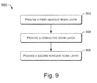
- FIGURE 9 is a flow diagram illustrating an exemplary process 600 for creating a structural adhesive film that includes a conductive scrim.
- the order in which the operations are described is not intended to be construed as a limitation, and any number of the described blocks can be combined in any order and/or in parallel to implement the process.
- a first resin adhesive layer may be provided.
- the resin adhesive layer is configured to be able to bond to a carbon fiber laminate ply, such as a carbon-fiber reinforced plastic (CFRP) ply.
- CFRP carbon-fiber reinforced plastic
- an electrically conductive scrim is provided, that is, bonded to the first resin adhesive layer.
- the conductive scrim may be in the configuration of a mesh comprised of intersecting (or non-intersecting) strands of conductive fibers.
- the conductive fibers may include both metallic and non-metallic materials.
- the conductive scrim may be bond to the combination with an additional binding agent, e.g., resin adhesive.
- a second resin adhesive layer may be provided to complete the structural adhesive film.
- the second resin adhesive layer may have the same qualities as the first resin adhesive layer. Accordingly to various embodiments, the conductive scrim and the first and second resin adhesive layers may be combined during bonding such that the conductive scrim is infused with resin from one or more of the resin layers.
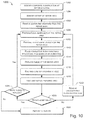
- FIGURE 10 is a flow diagram illustrating an exemplary process 1000 for conducting carbon fiber reinforced component repair using a structural adhesive film that includes a conductive scrim.
- the order in which the operations are described is not intended to be construed as a limitation, and any number of the described blocks can be combined in any order and/or in parallel to implement the process.
- a repair person may identify the composite configuration at a repair area on a carbon fiber reinforced component. For example, the repair person may identify the type of the composite laminate, the number of plies in the composite laminate, the ply orientations, the location of the conductive mesh with respect to the plies, and other factors.
- the repair person may identify the extent of the repair needed using any suitable detection method. The repair person may use, for example, visual inspection, microwave, acoustic, ultrasonic, or X-ray equipment, to identify the extent of the repair needed on the carbon fiber composite. In some instances, delamination in the repair area may be identified via sound generated by tapping on the delamination area.
- the delamination in the repair area may be detected using instruments that generate sound waves and also detect the attenuation of the generated sound waves. Using these assessment means, the size and depth (e.g. , the number of affected plies) of the repair area may be identified.
- the repair person may remove debris and moisture from the repair area.
- the removed debris may include any foreign matter present in the repair area, as well as any plies needing replacement (e.g. , delaminated plies) of the composite material.
- the repair person may prepare and clean one or more surfaces at the repair area. According to various embodiments, the preparation may involve grinding away the carbon fiber composite material to form a gradual tapered recess. Additionally, any corners in the repair area may be converted into circular or rounded shapes. Moreover, the repair person may prepare the tapered recess to expose at least a portion of any pre-existing conductive mesh that is present in the carbon fiber composite that is undergoing repair.
- the repair person may prepare one or more replacement plies for the repair area.
- the replacement plies are prepared to match the orientation of the plies in the original structure.
- the replacement plies are configured to restore the repair area to at least its original shape and/or strength.
- extra plies may be prepared for placement on top of the replacement plies.
- a structural adhesive film is placed into the taper recess.
- the structural adhesive film may be a conductive structural adhesive film described in FIGURE 3 .
- the conductive structural adhesive film may be positioned to provide electrical contact between the plies in the original structure and the replacement plies.
- the repair person may place the laminate plies over the one or more layers the electrically conductive scrim embedded structural adhesive film.
- the laminate plies may include replacement plies and if appropriate, extra plies.
- each of the replacement plies may be oriented to match each of the original plies in the carbon fiber reinforced component, and the one or more extra plies are oriented to match the original outer ply.
- an additional electrically conductive structural adhesive film may be positioned adjacent to the conductive mesh.
- the electrically conductive scrim embedded structural adhesive film may be positioned so that at least a portion of the conductive scrim makes electrical contact with a portion of the pre-existing conductive mesh. For example, the electrical contact may be sufficient to conduct away lightning discharges from the repair area. Additional laminates plies may then be placed over the additional conductive structural adhesive film.
- the repair person may perform a vacuum bag lay up of the repair area to debaulk and cure the added plies.
- the curing of the added plies may be accomplished by the aid of heating, such as by the use of heating blankets.
- the entire carbon fiber reinforced component under repair may be placed in an oven or autoclave to cure the added plies.
- the repair person may test and inspect the repaired area.
- the repair person may test and inspect the repaired area for delaminiations, proper curing, proper ply orientation, proper adhesion, and the like.
- an electrical conductivity test of the repaired area may be performed to ensure that the conductive scrim has been positioned to sufficiently enable the conduction of electrical charges away from the repaired area.
- one particular method for performing an electrical conductivity test on composite materials as disclosed in U.S. Patent Publication No. 2007/0096751 A1 to Georgeson et al., published on May 3, 2007 , is hereby incorporated by reference.
- the repair person may make a determination as to whether the repair is acceptable based on the test and inspection of the repair area. If a determination is made that the repair is not acceptable, ("no" at decision block 720), the one or more unacceptable plies and, if necessary, the structural adhesive films associated with the one or more plies may be removed. Following removal, the process 700 may loop back to block 708 where the repair person may repeat the repair.
- the process 1000 may proceed to decision block 1024.
- decision block 1024 a determination may be made as to whether the repair includes the replacement of additional plies. If there are more repair plies to be replaced, ("yes" at decision block 1024), the process 1000 may loop back to block 1008 where the repair person replaces additional laminate plies. However, if there are no more additional plies to be replaced, (“no" at decision block 1024), the carbon fiber reinforced component that includes the repaired area is then returned to service at block 1026.
- FIGURE 11 is a side elevational view of an aircraft 1100 that includes one or more carbon fiber reinforced components that may be repaired with a conductive scrim embedded structural adhesive film.
- aircraft may include, for example, and without limitation, the 787 model aircraft commercially-available from the Boeing Company of Chicago, Illinois.
- the aircraft 1100 includes one or more propulsion units 1104 coupled to a fuselage 1102, wing assemblies 1106 (or other lifting surfaces), a tail assembly 1108, a landing assembly 1110, a control system (not visible), and a host of other systems and subsystems that enable proper operation of the aircraft 1100.
- at least a portion of the wing assemblies 1106 may include one or more carbon fiber reinforced components.
- these components may be repaired using a structural adhesive film that includes a conductive scrim, as described in FIGURE 3 .
- the various embodiments of the electrically conductive scrim embedded structural adhesive film may also be used to repair other vehicles that include electrically conductive carbon fiber exterior components. These vehicles may include ships, trains, and any other vehicles.
- the electrically conductive scrim may advantageously protect the repaired carbon fiber reinforced components in these vehicles from lightning strikes and other electrical discharges, such as electrostatic discharges resulting from fuel electrification in fuel cells.
- Embodiments of systems and methods in accordance with the present disclosure may provide significant advantages over the prior art.
- a structural adhesive film that includes an electrically conductive scrim may enable electrical discharges from lightning strikes to be conducted away from a repaired area of a carbon fiber reinforced component.
- the electrically conductive scrim may advantageously minimize the effects of lightning strikes.
- the electrically conductive scrim may also be used to restore an electromagnetic field (EMF) shield and reduce or eliminate electrical arcing and thermal energy buildups from lightning strikes.
- EMF electromagnetic field
Landscapes
- Chemical & Material Sciences (AREA)
- Organic Chemistry (AREA)
- Engineering & Computer Science (AREA)
- Mechanical Engineering (AREA)
- Laminated Bodies (AREA)
Priority Applications (1)
| Application Number | Priority Date | Filing Date | Title |
|---|---|---|---|
| EP12179413.5A EP2527415B1 (en) | 2007-08-23 | 2008-08-21 | Conductive scrim embedded structural adhesive films |
Applications Claiming Priority (2)
| Application Number | Priority Date | Filing Date | Title |
|---|---|---|---|
| US11/844,174 US7628879B2 (en) | 2007-08-23 | 2007-08-23 | Conductive scrim embedded structural adhesive films |
| PCT/US2008/073869 WO2009026442A1 (en) | 2007-08-23 | 2008-08-21 | Conductive scrim embedded structural adhesive films |
Related Child Applications (2)
| Application Number | Title | Priority Date | Filing Date |
|---|---|---|---|
| EP12179413.5A Division-Into EP2527415B1 (en) | 2007-08-23 | 2008-08-21 | Conductive scrim embedded structural adhesive films |
| EP12179413.5A Division EP2527415B1 (en) | 2007-08-23 | 2008-08-21 | Conductive scrim embedded structural adhesive films |
Publications (2)
| Publication Number | Publication Date |
|---|---|
| EP2183330A1 EP2183330A1 (en) | 2010-05-12 |
| EP2183330B1 true EP2183330B1 (en) | 2016-10-05 |
Family
ID=39791316
Family Applications (2)
| Application Number | Title | Priority Date | Filing Date |
|---|---|---|---|
| EP08798374.8A Active EP2183330B1 (en) | 2007-08-23 | 2008-08-21 | Conductive scrim embedded structural adhesive films |
| EP12179413.5A Active EP2527415B1 (en) | 2007-08-23 | 2008-08-21 | Conductive scrim embedded structural adhesive films |
Family Applications After (1)
| Application Number | Title | Priority Date | Filing Date |
|---|---|---|---|
| EP12179413.5A Active EP2527415B1 (en) | 2007-08-23 | 2008-08-21 | Conductive scrim embedded structural adhesive films |
Country Status (7)
Families Citing this family (68)
| Publication number | Priority date | Publication date | Assignee | Title |
|---|---|---|---|---|
| US7849729B2 (en) | 2006-12-22 | 2010-12-14 | The Boeing Company | Leak detection in vacuum bags |
| US8568551B2 (en) | 2007-05-22 | 2013-10-29 | The Boeing Company | Pre-patterned layup kit and method of manufacture |
| US9770871B2 (en) * | 2007-05-22 | 2017-09-26 | The Boeing Company | Method and apparatus for layup placement |
| US8333864B2 (en) | 2008-09-30 | 2012-12-18 | The Boeing Company | Compaction of prepreg plies on composite laminate structures |
| US8936695B2 (en) | 2007-07-28 | 2015-01-20 | The Boeing Company | Method for forming and applying composite layups having complex geometries |
| US8707766B2 (en) | 2010-04-21 | 2014-04-29 | The Boeing Company | Leak detection in vacuum bags |
| US8916010B2 (en) | 2007-12-07 | 2014-12-23 | The Boeing Company | Composite manufacturing method |
| US8752293B2 (en) * | 2007-12-07 | 2014-06-17 | The Boeing Company | Method of fabricating structures using composite modules and structures made thereby |
| DE102008021788A1 (de) * | 2008-04-30 | 2009-11-12 | Deutsches Zentrum für Luft- und Raumfahrt e.V. | Verfahren zum Reparieren einer Flugzeugkomponente |
| US8449703B2 (en) * | 2009-03-09 | 2013-05-28 | The Boeing Company | Predictable bonded rework of composite structures using tailored patches |
| US8540909B2 (en) * | 2009-03-09 | 2013-09-24 | The Boeing Company | Method of reworking an area of a composite structure containing an inconsistency |
| US8524356B1 (en) | 2009-03-09 | 2013-09-03 | The Boeing Company | Bonded patch having multiple zones of fracture toughness |
| US9492975B2 (en) | 2009-03-09 | 2016-11-15 | The Boeing Company | Structural bonded patch with tapered adhesive design |
| US8409384B2 (en) * | 2009-03-09 | 2013-04-02 | The Boeing Company | Predictable bonded rework of composite structures |
| US8617694B1 (en) | 2009-03-09 | 2013-12-31 | The Boeing Company | Discretely tailored multi-zone bondline for fail-safe structural repair |
| US20100233424A1 (en) * | 2009-03-10 | 2010-09-16 | The Boeing Company | Composite structures employing quasi-isotropic laminates |
| AU2010224241B2 (en) * | 2009-03-11 | 2014-03-27 | Deepflex Inc. | Method and apparatus to repair flexible fiber-reinforced pipe |
| US8857128B2 (en) * | 2009-05-18 | 2014-10-14 | Apple Inc. | Reinforced device housing |
| JP5439963B2 (ja) * | 2009-06-12 | 2014-03-12 | 三菱電機株式会社 | ソーラーアレイパネル、ソーラーアレイパネルの補修方法 |
| GB2474897B (en) * | 2009-11-02 | 2015-09-16 | Hexcel Composites Ltd | Electromagnetic hazard protector for composite materials |
| US8408972B2 (en) * | 2010-01-25 | 2013-04-02 | Apple Inc. | Apparatus and method for intricate cuts |
| US8511498B2 (en) * | 2010-01-25 | 2013-08-20 | Apple Inc. | Method for manufacturing an electronic device enclosure |
| DE102010042970A1 (de) * | 2010-05-12 | 2011-11-17 | Airbus Operations Gmbh | Strukturbauteil mit verbesserter Leitfähigkeit und mechanischer Festigkeit sowie Verfahren zu dessen Herstellung |
| US8372495B2 (en) | 2010-05-26 | 2013-02-12 | Apple Inc. | Electronic device enclosure using sandwich construction |
| US9120272B2 (en) | 2010-07-22 | 2015-09-01 | Apple Inc. | Smooth composite structure |
| JP5615165B2 (ja) * | 2010-12-27 | 2014-10-29 | 三菱重工業株式会社 | 複合材パネル構造体及びその製造方法 |
| FR2970238B1 (fr) * | 2011-01-07 | 2013-01-25 | Airbus Operations Sas | Piece et procede de reparation d'une structure endommagee, en particulier de peau d'aeronef, ainsi qu'un kit de reparation de mise en oeuvre |
| US9011623B2 (en) | 2011-03-03 | 2015-04-21 | Apple Inc. | Composite enclosure |
| WO2012154544A2 (en) * | 2011-05-06 | 2012-11-15 | Purdue Research Foundation | Method and system of vacuum assisted resin transfer molding for repair of composite materials and structure |
| MX352310B (es) | 2011-09-07 | 2017-11-17 | Afton Chemical Corp | Sistema de suministro de aditivo de motor aerotransportado. |
| US20130143006A1 (en) * | 2011-12-02 | 2013-06-06 | The Boeing Company | Reducing Porosity in Composite Structures |
| JPWO2013108311A1 (ja) * | 2012-01-16 | 2015-05-11 | Necカシオモバイルコミュニケーションズ株式会社 | 携帯端末装置 |
| DE102012001056A1 (de) * | 2012-01-20 | 2013-07-25 | Liebherr-Aerospace Lindenberg Gmbh | Fahrwerkskomponente aus einem Faserverbundwerkstoff |
| US9849640B2 (en) * | 2012-03-28 | 2017-12-26 | Bell Helicopter Textron Inc. | Processes for repairing complex laminated composites |
| DE102012205633A1 (de) * | 2012-04-05 | 2013-10-10 | Airbus Operations Gmbh | Verfahren und Vorrichtung zum Fügen von toleranzbehafteten Fügepartnern |
| US20130269998A1 (en) * | 2012-04-13 | 2013-10-17 | Apple Inc. | System and method for optimizing and combining adhesive parameters |
| US20140117022A1 (en) * | 2012-10-30 | 2014-05-01 | The Boeing Company | Composite Structures Having Bondlines with Matched Electrical Conductivity |
| JP6124561B2 (ja) * | 2012-11-20 | 2017-05-10 | 三菱航空機株式会社 | 複合材の修理方法 |
| US10407955B2 (en) | 2013-03-13 | 2019-09-10 | Apple Inc. | Stiff fabric |
| JP6300449B2 (ja) * | 2013-03-28 | 2018-03-28 | 三菱航空機株式会社 | 被修理部の修理方法および修理装置 |
| CN104831470B (zh) | 2013-12-20 | 2018-07-27 | 苹果公司 | 利用编织纤维增加抗张强度并用于固定附连机制 |
| CN103862686A (zh) * | 2014-02-22 | 2014-06-18 | 李文忠 | 非导磁性材料的工程施工热熔性胶粘技术 |
| JP6321429B2 (ja) * | 2014-03-31 | 2018-05-09 | 学校法人大同学園 | 繊維強化樹脂部材の修理方法および研削方法 |
| EP2926984B1 (de) * | 2014-04-03 | 2019-02-20 | Nordex Energy GmbH | Verfahren zum Reparieren eines elektrischen Heizelements eines Windenergieanlagenrotorblatts |
| EP3137288B1 (en) * | 2014-05-01 | 2019-11-20 | The Boeing Company | Structural bonded patch with tapered adhesive design |
| US9545782B2 (en) * | 2014-05-13 | 2017-01-17 | The Boeing Company | Method and apparatus for repairing composite materials |
| JP6165682B2 (ja) * | 2014-06-30 | 2017-07-19 | 三菱重工業株式会社 | 風車の翼、および、風車の翼の修理方法 |
| US10213964B2 (en) * | 2015-05-08 | 2019-02-26 | The Boeing Company | Methods and apparatus for repairing composite materials |
| KR101836566B1 (ko) | 2015-05-15 | 2018-03-08 | 현대자동차주식회사 | 도전성 접착제 및 이를 이용한 복합소재의 접합방법 |
| DE102015110193A1 (de) * | 2015-06-24 | 2016-12-29 | Airbus Operations Gmbh | Verfahren zum Schweißverbinden zweier Komponenten aus einem thermoplastischen Schichtverbundwerkstoff |
| GB201519877D0 (en) * | 2015-11-11 | 2015-12-23 | Short Brothers Plc | Methods and patches for repairing composite laminates |
| GB201522539D0 (en) * | 2015-12-21 | 2016-02-03 | Hexcel Composites Ltd | Improvements in or relating to electrically conducting materials |
| US9827688B2 (en) * | 2016-01-12 | 2017-11-28 | The Boeing Company | Patch fabrication system |
| EP3564184B1 (en) * | 2016-04-08 | 2023-03-01 | Airbus Defence and Space GmbH | Structural fibre-reinforced component with lightning strike protection by using carbon nano tube mats and metallic layers |
| US9972896B2 (en) | 2016-06-23 | 2018-05-15 | General Electric Company | Wireless aircraft engine monitoring system |
| JP6820753B2 (ja) * | 2017-01-16 | 2021-01-27 | 三菱重工業株式会社 | 修理パッチの成形方法 |
| JP6847679B2 (ja) * | 2017-01-20 | 2021-03-24 | 三菱重工業株式会社 | 複合材の修理方法 |
| US10710352B2 (en) * | 2017-07-11 | 2020-07-14 | The Boeing Company | Structural pre-cured repair patch for repair to highly loaded primary and secondary structural components |
| US10864686B2 (en) | 2017-09-25 | 2020-12-15 | Apple Inc. | Continuous carbon fiber winding for thin structural ribs |
| CN110196286A (zh) * | 2018-02-26 | 2019-09-03 | 漆松林 | 一种对比试块 |
| CN110196278A (zh) * | 2018-02-26 | 2019-09-03 | 漆松林 | 一种修补质量评价方法 |
| DK3712423T3 (da) * | 2019-03-21 | 2023-01-30 | Siemens Gamesa Renewable Energy As | Fremgangsmåde til reparation af et beskadiget bjælkedæksel af en vindmøllevinge af en vindmølle |
| US11827821B2 (en) * | 2021-02-04 | 2023-11-28 | The Boeing Company | Method for curing a patch |
| US11199287B1 (en) * | 2021-02-23 | 2021-12-14 | Trinity Bay Equipment Holdings, LLC | Multi-layer pipe tubing repair systems and methods |
| US11549391B2 (en) | 2021-03-22 | 2023-01-10 | General Electric Company | Component formed from hybrid material |
| US12090708B2 (en) * | 2021-12-16 | 2024-09-17 | Textron Innovations Inc. | Self heating structural adhesives for out-of-autoclave and out-of-oven curing |
| GB202206057D0 (en) * | 2022-04-26 | 2022-06-08 | Lm Wind Power As | Wind turbine blade repair |
| CN115042458B (zh) * | 2022-06-22 | 2024-06-18 | 沈阳飞机工业(集团)有限公司 | 一种可用于飞机盒段结构复合材料构件的胶接修补工艺 |
Family Cites Families (24)
| Publication number | Priority date | Publication date | Assignee | Title |
|---|---|---|---|---|
| US4352142A (en) * | 1981-04-15 | 1982-09-28 | The Boeing Company | Composite aircraft structure having lightning protection |
| US4448838A (en) * | 1981-09-04 | 1984-05-15 | Lear Fan Corp. | Graphite fiber reinforced laminate structure capable of withstanding lightning strikes |
| US4428867A (en) * | 1981-11-02 | 1984-01-31 | Lockheed Corporation | Electrically conductive structural adhesive |
| US4978404A (en) * | 1986-07-21 | 1990-12-18 | The Boeing Company | Method for repairing a hole in a structural wall of composite material |
| US4839771A (en) * | 1987-12-04 | 1989-06-13 | The Boeing Company | Apparatus for providing a lightning protective vehicle surface |
| US5338827A (en) * | 1990-01-30 | 1994-08-16 | Trw Inc. | Polyimide resins useful at high temperatures |
| US5160771A (en) * | 1990-09-27 | 1992-11-03 | Structural Laminates Company | Joining metal-polymer-metal laminate sections |
| GB9107766D0 (en) * | 1991-04-12 | 1991-06-05 | Short Brothers Plc | A structural component |
| CA2099808C (en) | 1992-07-06 | 2000-11-07 | Minoru Harada | Vapor-grown and graphitized carbon fibers, process for preparing same, molded members thereof, and composite members thereof |
| FR2728395A1 (fr) * | 1994-12-16 | 1996-06-21 | Eurocopter France | Element en materiau composite avec assemblage(s) de continuite electrique a travers l'element, son procede de fabrication et son utilisation en aeronautique |
| GB9504372D0 (en) * | 1995-03-04 | 1995-04-26 | British Aerospace | A composite laminate |
| US5958166A (en) * | 1996-12-31 | 1999-09-28 | Mcdonnell Douglas Corporation | Method for repairing high temperature composite structures |
| GB9807198D0 (en) * | 1998-04-04 | 1998-06-03 | British Aerospace | Adhesively bonded joints in carbon fibre composite structures |
| JP3666719B2 (ja) * | 1998-04-20 | 2005-06-29 | タキロン株式会社 | 電磁波シールド板の接合構造及び導電性接合材 |
| US6174392B1 (en) * | 1999-03-04 | 2001-01-16 | Northrop Grumman Corporation | Composite structure repair process |
| US7223312B2 (en) * | 2000-09-21 | 2007-05-29 | Integument Technologies, Inc. | Methods and materials for reducing damage from environmental electromagnetic effects |
| US7432448B2 (en) * | 2001-02-15 | 2008-10-07 | Integral Technologies, Inc | Low cost aircraft structures and avionics manufactured from conductive loaded resin-based materials |
| JP2004087824A (ja) | 2002-08-27 | 2004-03-18 | Sii Micro Parts Ltd | 電気二重層キャパシタ |
| US6919504B2 (en) * | 2002-12-19 | 2005-07-19 | 3M Innovative Properties Company | Flexible heat sink |
| US20050242471A1 (en) * | 2004-04-30 | 2005-11-03 | Bhatt Sanjiv M | Methods for continuously producing shaped articles |
| KR101261064B1 (ko) | 2004-08-23 | 2013-05-06 | 제너럴 일렉트릭 캄파니 | 열 전도성 조성물 및 그의 제조 방법 |
| JP2006219078A (ja) * | 2005-02-14 | 2006-08-24 | Honda Motor Co Ltd | 航空機用複合体及び航空機の複合体構造部の製造方法 |
| US7312608B2 (en) | 2005-11-03 | 2007-12-25 | The Boeing Company | Systems and methods for inspecting electrical conductivity in composite materials |
| KR20080004021A (ko) | 2006-07-04 | 2008-01-09 | 쓰리엠 이노베이티브 프로퍼티즈 캄파니 | 양면의 접착력이 서로 다른 전도성 점착 테이프 및 그제조방법 |
-
2007
- 2007-08-23 US US11/844,174 patent/US7628879B2/en active Active
-
2008
- 2008-08-21 PT PT121794135T patent/PT2527415T/pt unknown
- 2008-08-21 EP EP08798374.8A patent/EP2183330B1/en active Active
- 2008-08-21 JP JP2010522027A patent/JP2010536622A/ja active Pending
- 2008-08-21 EP EP12179413.5A patent/EP2527415B1/en active Active
- 2008-08-21 CN CN201410190753.3A patent/CN104017505B/zh active Active
- 2008-08-21 PT PT87983748T patent/PT2183330T/pt unknown
- 2008-08-21 ES ES08798374.8T patent/ES2603187T3/es active Active
- 2008-08-21 WO PCT/US2008/073869 patent/WO2009026442A1/en active Application Filing
- 2008-08-21 CN CN200880113066.4A patent/CN101910339B/zh active Active
- 2008-08-21 ES ES12179413.5T patent/ES2602984T3/es active Active
-
2013
- 2013-05-30 JP JP2013114148A patent/JP5805706B2/ja active Active
Also Published As
| Publication number | Publication date |
|---|---|
| EP2183330A1 (en) | 2010-05-12 |
| ES2603187T3 (es) | 2017-02-24 |
| CN104017505B (zh) | 2016-03-02 |
| PT2183330T (pt) | 2016-12-20 |
| US7628879B2 (en) | 2009-12-08 |
| JP5805706B2 (ja) | 2015-11-04 |
| CN101910339B (zh) | 2014-07-23 |
| JP2010536622A (ja) | 2010-12-02 |
| CN104017505A (zh) | 2014-09-03 |
| US20090053406A1 (en) | 2009-02-26 |
| EP2527415A1 (en) | 2012-11-28 |
| CN101910339A (zh) | 2010-12-08 |
| JP2013216101A (ja) | 2013-10-24 |
| EP2527415B1 (en) | 2016-10-05 |
| PT2527415T (pt) | 2016-12-13 |
| ES2602984T3 (es) | 2017-02-23 |
| WO2009026442A1 (en) | 2009-02-26 |
Similar Documents
| Publication | Publication Date | Title |
|---|---|---|
| EP2183330B1 (en) | Conductive scrim embedded structural adhesive films | |
| US8784589B2 (en) | Copper grid repair technique for lightning strike protection | |
| EP1928649B1 (en) | Copper grid repair technique for lightning strike protection | |
| CA2841071C (en) | Molybdenum composite hybrid laminates and methods | |
| JP6941422B2 (ja) | 落雷防護相互接続を有する多層複合材構造体及び外板留め具から雷電流をそらす方法 | |
| US8231751B2 (en) | Repair technique for lightning strike protection | |
| US20070281122A1 (en) | Method and apparatus for dissipating electric energy in a composite structure | |
| EP2810777B1 (en) | Heating layer for film removal | |
| US10472473B2 (en) | Enhancing z-conductivity in carbon fiber reinforced plastic composite layups | |
| WO2017081456A1 (en) | Methods and patches for repairing composite laminates | |
| CA2890769A1 (en) | Methods and apparatus for use in forming a lightning protection system | |
| CA2883719C (en) | Composite structures having bondlines with matched electrical conductivity | |
| EP2628589A1 (en) | Composite layers with exposed reinforcement | |
| Hebert | Design of lightweight perforated copper foil for lightning protection of fiber reinforced plastic | |
| Hebert | AUTOMATED FIBER PLACEMENT OF LIGHTNING PROTECTION SURFACER FOR CARBON FIBER REINFORCED PLASTIC | |
| HK1111942B (en) | Copper grid repair technique for lightning strike protection |
Legal Events
| Date | Code | Title | Description |
|---|---|---|---|
| PUAI | Public reference made under article 153(3) epc to a published international application that has entered the european phase |
Free format text: ORIGINAL CODE: 0009012 |
|
| 17P | Request for examination filed |
Effective date: 20100308 |
|
| AK | Designated contracting states |
Kind code of ref document: A1 Designated state(s): AT BE BG CH CY CZ DE DK EE ES FI FR GB GR HR HU IE IS IT LI LT LU LV MC MT NL NO PL PT RO SE SI SK TR |
|
| AX | Request for extension of the european patent |
Extension state: AL BA MK RS |
|
| 17Q | First examination report despatched |
Effective date: 20100728 |
|
| DAX | Request for extension of the european patent (deleted) | ||
| GRAP | Despatch of communication of intention to grant a patent |
Free format text: ORIGINAL CODE: EPIDOSNIGR1 |
|
| INTG | Intention to grant announced |
Effective date: 20160314 |
|
| GRAS | Grant fee paid |
Free format text: ORIGINAL CODE: EPIDOSNIGR3 |
|
| GRAA | (expected) grant |
Free format text: ORIGINAL CODE: 0009210 |
|
| AK | Designated contracting states |
Kind code of ref document: B1 Designated state(s): AT BE BG CH CY CZ DE DK EE ES FI FR GB GR HR HU IE IS IT LI LT LU LV MC MT NL NO PL PT RO SE SI SK TR |
|
| REG | Reference to a national code |
Ref country code: GB Ref legal event code: FG4D |
|
| REG | Reference to a national code |
Ref country code: CH Ref legal event code: EP |
|
| REG | Reference to a national code |
Ref country code: AT Ref legal event code: REF Ref document number: 834645 Country of ref document: AT Kind code of ref document: T Effective date: 20161015 |
|
| REG | Reference to a national code |
Ref country code: IE Ref legal event code: FG4D |
|
| REG | Reference to a national code |
Ref country code: DE Ref legal event code: R096 Ref document number: 602008046696 Country of ref document: DE |
|
| REG | Reference to a national code |
Ref country code: SE Ref legal event code: TRGR Ref country code: PT Ref legal event code: SC4A Ref document number: 2183330 Country of ref document: PT Date of ref document: 20161220 Kind code of ref document: T Free format text: AVAILABILITY OF NATIONAL TRANSLATION Effective date: 20161202 |
|
| REG | Reference to a national code |
Ref country code: NL Ref legal event code: MP Effective date: 20161005 |
|
| REG | Reference to a national code |
Ref country code: LT Ref legal event code: MG4D |
|
| REG | Reference to a national code |
Ref country code: ES Ref legal event code: FG2A Ref document number: 2603187 Country of ref document: ES Kind code of ref document: T3 Effective date: 20170224 |
|
| PG25 | Lapsed in a contracting state [announced via postgrant information from national office to epo] |
Ref country code: LV Free format text: LAPSE BECAUSE OF FAILURE TO SUBMIT A TRANSLATION OF THE DESCRIPTION OR TO PAY THE FEE WITHIN THE PRESCRIBED TIME-LIMIT Effective date: 20161005 |
|
| REG | Reference to a national code |
Ref country code: AT Ref legal event code: MK05 Ref document number: 834645 Country of ref document: AT Kind code of ref document: T Effective date: 20161005 |
|
| PG25 | Lapsed in a contracting state [announced via postgrant information from national office to epo] |
Ref country code: LT Free format text: LAPSE BECAUSE OF FAILURE TO SUBMIT A TRANSLATION OF THE DESCRIPTION OR TO PAY THE FEE WITHIN THE PRESCRIBED TIME-LIMIT Effective date: 20161005 Ref country code: GR Free format text: LAPSE BECAUSE OF FAILURE TO SUBMIT A TRANSLATION OF THE DESCRIPTION OR TO PAY THE FEE WITHIN THE PRESCRIBED TIME-LIMIT Effective date: 20170106 Ref country code: NO Free format text: LAPSE BECAUSE OF FAILURE TO SUBMIT A TRANSLATION OF THE DESCRIPTION OR TO PAY THE FEE WITHIN THE PRESCRIBED TIME-LIMIT Effective date: 20170105 |
|
| PG25 | Lapsed in a contracting state [announced via postgrant information from national office to epo] |
Ref country code: FI Free format text: LAPSE BECAUSE OF FAILURE TO SUBMIT A TRANSLATION OF THE DESCRIPTION OR TO PAY THE FEE WITHIN THE PRESCRIBED TIME-LIMIT Effective date: 20161005 Ref country code: NL Free format text: LAPSE BECAUSE OF FAILURE TO SUBMIT A TRANSLATION OF THE DESCRIPTION OR TO PAY THE FEE WITHIN THE PRESCRIBED TIME-LIMIT Effective date: 20161005 Ref country code: HR Free format text: LAPSE BECAUSE OF FAILURE TO SUBMIT A TRANSLATION OF THE DESCRIPTION OR TO PAY THE FEE WITHIN THE PRESCRIBED TIME-LIMIT Effective date: 20161005 Ref country code: BE Free format text: LAPSE BECAUSE OF FAILURE TO SUBMIT A TRANSLATION OF THE DESCRIPTION OR TO PAY THE FEE WITHIN THE PRESCRIBED TIME-LIMIT Effective date: 20161005 Ref country code: PL Free format text: LAPSE BECAUSE OF FAILURE TO SUBMIT A TRANSLATION OF THE DESCRIPTION OR TO PAY THE FEE WITHIN THE PRESCRIBED TIME-LIMIT Effective date: 20161005 Ref country code: IS Free format text: LAPSE BECAUSE OF FAILURE TO SUBMIT A TRANSLATION OF THE DESCRIPTION OR TO PAY THE FEE WITHIN THE PRESCRIBED TIME-LIMIT Effective date: 20170205 Ref country code: AT Free format text: LAPSE BECAUSE OF FAILURE TO SUBMIT A TRANSLATION OF THE DESCRIPTION OR TO PAY THE FEE WITHIN THE PRESCRIBED TIME-LIMIT Effective date: 20161005 |
|
| REG | Reference to a national code |
Ref country code: DE Ref legal event code: R097 Ref document number: 602008046696 Country of ref document: DE |
|
| PG25 | Lapsed in a contracting state [announced via postgrant information from national office to epo] |
Ref country code: RO Free format text: LAPSE BECAUSE OF FAILURE TO SUBMIT A TRANSLATION OF THE DESCRIPTION OR TO PAY THE FEE WITHIN THE PRESCRIBED TIME-LIMIT Effective date: 20161005 Ref country code: DK Free format text: LAPSE BECAUSE OF FAILURE TO SUBMIT A TRANSLATION OF THE DESCRIPTION OR TO PAY THE FEE WITHIN THE PRESCRIBED TIME-LIMIT Effective date: 20161005 Ref country code: SK Free format text: LAPSE BECAUSE OF FAILURE TO SUBMIT A TRANSLATION OF THE DESCRIPTION OR TO PAY THE FEE WITHIN THE PRESCRIBED TIME-LIMIT Effective date: 20161005 Ref country code: EE Free format text: LAPSE BECAUSE OF FAILURE TO SUBMIT A TRANSLATION OF THE DESCRIPTION OR TO PAY THE FEE WITHIN THE PRESCRIBED TIME-LIMIT Effective date: 20161005 Ref country code: CZ Free format text: LAPSE BECAUSE OF FAILURE TO SUBMIT A TRANSLATION OF THE DESCRIPTION OR TO PAY THE FEE WITHIN THE PRESCRIBED TIME-LIMIT Effective date: 20161005 |
|
| PLBE | No opposition filed within time limit |
Free format text: ORIGINAL CODE: 0009261 |
|
| STAA | Information on the status of an ep patent application or granted ep patent |
Free format text: STATUS: NO OPPOSITION FILED WITHIN TIME LIMIT |
|
| REG | Reference to a national code |
Ref country code: FR Ref legal event code: PLFP Year of fee payment: 10 |
|
| PG25 | Lapsed in a contracting state [announced via postgrant information from national office to epo] |
Ref country code: BG Free format text: LAPSE BECAUSE OF FAILURE TO SUBMIT A TRANSLATION OF THE DESCRIPTION OR TO PAY THE FEE WITHIN THE PRESCRIBED TIME-LIMIT Effective date: 20170105 |
|
| 26N | No opposition filed |
Effective date: 20170706 |
|
| PG25 | Lapsed in a contracting state [announced via postgrant information from national office to epo] |
Ref country code: SI Free format text: LAPSE BECAUSE OF FAILURE TO SUBMIT A TRANSLATION OF THE DESCRIPTION OR TO PAY THE FEE WITHIN THE PRESCRIBED TIME-LIMIT Effective date: 20161005 |
|
| REG | Reference to a national code |
Ref country code: CH Ref legal event code: PL |
|
| PG25 | Lapsed in a contracting state [announced via postgrant information from national office to epo] |
Ref country code: MC Free format text: LAPSE BECAUSE OF FAILURE TO SUBMIT A TRANSLATION OF THE DESCRIPTION OR TO PAY THE FEE WITHIN THE PRESCRIBED TIME-LIMIT Effective date: 20161005 |
|
| PG25 | Lapsed in a contracting state [announced via postgrant information from national office to epo] |
Ref country code: CH Free format text: LAPSE BECAUSE OF NON-PAYMENT OF DUE FEES Effective date: 20170831 Ref country code: LI Free format text: LAPSE BECAUSE OF NON-PAYMENT OF DUE FEES Effective date: 20170831 |
|
| REG | Reference to a national code |
Ref country code: IE Ref legal event code: MM4A |
|
| PG25 | Lapsed in a contracting state [announced via postgrant information from national office to epo] |
Ref country code: LU Free format text: LAPSE BECAUSE OF NON-PAYMENT OF DUE FEES Effective date: 20170821 |
|
| PG25 | Lapsed in a contracting state [announced via postgrant information from national office to epo] |
Ref country code: IE Free format text: LAPSE BECAUSE OF NON-PAYMENT OF DUE FEES Effective date: 20170821 |
|
| REG | Reference to a national code |
Ref country code: FR Ref legal event code: PLFP Year of fee payment: 11 |
|
| PG25 | Lapsed in a contracting state [announced via postgrant information from national office to epo] |
Ref country code: MT Free format text: LAPSE BECAUSE OF NON-PAYMENT OF DUE FEES Effective date: 20170821 |
|
| PG25 | Lapsed in a contracting state [announced via postgrant information from national office to epo] |
Ref country code: HU Free format text: LAPSE BECAUSE OF FAILURE TO SUBMIT A TRANSLATION OF THE DESCRIPTION OR TO PAY THE FEE WITHIN THE PRESCRIBED TIME-LIMIT; INVALID AB INITIO Effective date: 20080821 |
|
| PG25 | Lapsed in a contracting state [announced via postgrant information from national office to epo] |
Ref country code: CY Free format text: LAPSE BECAUSE OF NON-PAYMENT OF DUE FEES Effective date: 20161005 |
|
| REG | Reference to a national code |
Ref country code: DE Ref legal event code: R082 Ref document number: 602008046696 Country of ref document: DE Representative=s name: MAIER, LL.M., MICHAEL C., DE Ref country code: DE Ref legal event code: R082 Ref document number: 602008046696 Country of ref document: DE Representative=s name: BOULT WADE TENNANT LLP, DE |
|
| REG | Reference to a national code |
Ref country code: DE Ref legal event code: R082 Ref document number: 602008046696 Country of ref document: DE Representative=s name: BOULT WADE TENNANT LLP, DE |
|
| PG25 | Lapsed in a contracting state [announced via postgrant information from national office to epo] |
Ref country code: TR Free format text: LAPSE BECAUSE OF FAILURE TO SUBMIT A TRANSLATION OF THE DESCRIPTION OR TO PAY THE FEE WITHIN THE PRESCRIBED TIME-LIMIT Effective date: 20161005 |
|
| P01 | Opt-out of the competence of the unified patent court (upc) registered |
Effective date: 20230516 |
|
| PGFP | Annual fee paid to national office [announced via postgrant information from national office to epo] |
Ref country code: DE Payment date: 20240828 Year of fee payment: 17 |
|
| PGFP | Annual fee paid to national office [announced via postgrant information from national office to epo] |
Ref country code: GB Payment date: 20240827 Year of fee payment: 17 Ref country code: PT Payment date: 20240801 Year of fee payment: 17 |
|
| PGFP | Annual fee paid to national office [announced via postgrant information from national office to epo] |
Ref country code: FR Payment date: 20240826 Year of fee payment: 17 |
|
| PGFP | Annual fee paid to national office [announced via postgrant information from national office to epo] |
Ref country code: ES Payment date: 20240902 Year of fee payment: 17 |
|
| PGFP | Annual fee paid to national office [announced via postgrant information from national office to epo] |
Ref country code: IT Payment date: 20240822 Year of fee payment: 17 Ref country code: SE Payment date: 20240827 Year of fee payment: 17 |