EP2177789B1 - Stellantrieb mit einem Elektromotor und einem Planetengetriebe - Google Patents
Stellantrieb mit einem Elektromotor und einem Planetengetriebe Download PDFInfo
- Publication number
- EP2177789B1 EP2177789B1 EP09012174A EP09012174A EP2177789B1 EP 2177789 B1 EP2177789 B1 EP 2177789B1 EP 09012174 A EP09012174 A EP 09012174A EP 09012174 A EP09012174 A EP 09012174A EP 2177789 B1 EP2177789 B1 EP 2177789B1
- Authority
- EP
- European Patent Office
- Prior art keywords
- planet
- ring gear
- gear
- gears
- planetary
- Prior art date
- Legal status (The legal status is an assumption and is not a legal conclusion. Google has not performed a legal analysis and makes no representation as to the accuracy of the status listed.)
- Not-in-force
Links
Images


Classifications
-
- F—MECHANICAL ENGINEERING; LIGHTING; HEATING; WEAPONS; BLASTING
- F16—ENGINEERING ELEMENTS AND UNITS; GENERAL MEASURES FOR PRODUCING AND MAINTAINING EFFECTIVE FUNCTIONING OF MACHINES OR INSTALLATIONS; THERMAL INSULATION IN GENERAL
- F16H—GEARING
- F16H57/00—General details of gearing
- F16H57/08—General details of gearing of gearings with members having orbital motion
- F16H57/082—Planet carriers
-
- H—ELECTRICITY
- H02—GENERATION; CONVERSION OR DISTRIBUTION OF ELECTRIC POWER
- H02K—DYNAMO-ELECTRIC MACHINES
- H02K7/00—Arrangements for handling mechanical energy structurally associated with dynamo-electric machines, e.g. structural association with mechanical driving motors or auxiliary dynamo-electric machines
- H02K7/10—Structural association with clutches, brakes, gears, pulleys or mechanical starters
- H02K7/116—Structural association with clutches, brakes, gears, pulleys or mechanical starters with gears
-
- F—MECHANICAL ENGINEERING; LIGHTING; HEATING; WEAPONS; BLASTING
- F16—ENGINEERING ELEMENTS AND UNITS; GENERAL MEASURES FOR PRODUCING AND MAINTAINING EFFECTIVE FUNCTIONING OF MACHINES OR INSTALLATIONS; THERMAL INSULATION IN GENERAL
- F16H—GEARING
- F16H55/00—Elements with teeth or friction surfaces for conveying motion; Worms, pulleys or sheaves for gearing mechanisms
- F16H55/02—Toothed members; Worms
- F16H55/17—Toothed wheels
- F16H2055/176—Ring gears with inner teeth
-
- F—MECHANICAL ENGINEERING; LIGHTING; HEATING; WEAPONS; BLASTING
- F16—ENGINEERING ELEMENTS AND UNITS; GENERAL MEASURES FOR PRODUCING AND MAINTAINING EFFECTIVE FUNCTIONING OF MACHINES OR INSTALLATIONS; THERMAL INSULATION IN GENERAL
- F16H—GEARING
- F16H57/00—General details of gearing
- F16H57/02—Gearboxes; Mounting gearing therein
- F16H57/023—Mounting or installation of gears or shafts in the gearboxes, e.g. methods or means for assembly
-
- Y—GENERAL TAGGING OF NEW TECHNOLOGICAL DEVELOPMENTS; GENERAL TAGGING OF CROSS-SECTIONAL TECHNOLOGIES SPANNING OVER SEVERAL SECTIONS OF THE IPC; TECHNICAL SUBJECTS COVERED BY FORMER USPC CROSS-REFERENCE ART COLLECTIONS [XRACs] AND DIGESTS
- Y10—TECHNICAL SUBJECTS COVERED BY FORMER USPC
- Y10T—TECHNICAL SUBJECTS COVERED BY FORMER US CLASSIFICATION
- Y10T29/00—Metal working
- Y10T29/49—Method of mechanical manufacture
- Y10T29/49462—Gear making
- Y10T29/49464—Assembling of gear into force transmitting device
Definitions
- the invention relates to an actuator, consisting of an electric motor and a planetary gear, comprising a ring gear, a planet carrier and a plurality of planetary gears mounted on the planet carrier, wherein the planet gears in the region of their outer teeth each have a front in the joining direction end face and the ring gear in the region of its internal teeth having the planetary gears associated angular ranges of the joining direction opposite end face in a defined angular position of the planet carrier to the ring gear, wherein the axial distance between the end face of the first planetary gear and the first angular range of the ring gear associated therewith from the axial distance between the end face of the second planetary gear and the differentiates him assigned second angular range of the ring gear.
- the US 5,800,305 A as well as the US 2005/192151 A1 show multi-stage planetary gear, in which also have the end faces of the planet gears different axial distances to the ring gear.
- Object of the present invention is therefore to provide in a generic actuator to ensure that an economic and time-decoupled simple and fast assembly of the three planet gears in the ring gear is possible without thereby increasing the manufacturing cost, with only minor changes to existing forms are needed.
- This object is achieved in that none of the angular ranges of the joining direction opposite end face of the ring gear is part of a plane to which one of the other angle ranges heard, the planes being aligned parallel to each other and at right angles to the axis of symmetry of the actuator.
- the individual planetary gears arrive independently of one another in the assembly-critical toothed region of the ring gear, so that an easier self-alignment of the planetary gears is possible. This increases the assembly speed and reduces the error rate during assembly.
- the invention is applicable to planetary gear with two or more planet gears in the same gear stage.
- the planet gears have different thickness in the axial direction.
- the temporal decoupling can be achieved during assembly.
- the disadvantage is that different items are necessary.
- this solution could lead to unwanted noise at higher speeds, so this solution is not preferred.
- the planet carrier has axle journals on which the planetary gears are radially mounted and that the planet carrier has axial stop ring surfaces on which the planet gears are axially mounted, wherein the stop ring surfaces protrude differently far axially.
- these stop ring surfaces can be produced without difficulty.
- a third (not claimed) alternative is provided that the end faces of the planetary gears are arranged in the assembled state in different axial position, wherein the planetary gears have the same tooth width and projecting annular surfaces on both sides of the teeth of the planetary gears to different degrees axially.
- the respective sprockets are integrally formed with hubs or connected by press fitting, the sprockets are arranged offset from one another axially different degrees.
- the first and third planet gears may be formed identically, being mounted only rotated by 180 ° to achieve a different axial displacement.
- the second planet gear differs from the first and third planet gears, but may be symmetrically shaped to a center plane and thus mounted in both possible orientations.
- the following figures each show three planet wheels per gear stage and also only one gear stage, but the invention also includes planetary gear with two, four or more planet gears per gear stage and multi-stage planetary gear. Further, the actuators may include additional gear stages of other types of gears, such as spur, worm or bevel gear and motor axis does not need to be aligned with the planetary gear axis.
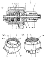
- Fig. 1 shows a sectional view through an actuator 1, consisting of an electric motor 2 and a planetary gear 3.
- the electric motor is a commutator, with a housing pot 18, a wound rotor 19 with a commutator 20 and a brush bridge, which serves as a bearing plate 13.
- the planetary gear comprises a ring gear 4, a Sun gear 14, a planet carrier 5 and planet gears 6a, 6b, 6c.
- the output of the planetary gear 3 is connected by gearing to a rack and pinion gear.
- the actuator serves as an EGR drive.
- Fig. 2 shows a mounted planet carrier 5, which is equipped with three different width planetary gears 6a, 6b, 6c.
- the end faces 7a, 7b, 7c of the planet gears 6a, 6b, 6c lie in different planes parallel to each other, so that during assembly of the assembled planet carrier 5 in the joining direction F, first the planet gear 6a, then 6b and 6c into engagement with the teeth of the ring gear come.
- Fig. 3a shows an alternative planetary carrier 5 (without journals 10), wherein the planet carrier Anlaufring vom 11a, 11b, 11c, which are part of different parallel planes, that project different distances from the plane of the planet carrier (web).
- the same planet carrier 5 is equipped with planet wheels 6a, 6b, 6c.
- the planet gears have thrust ring surfaces 16a, 16b, 16c, which face away from the planet carrier.
- thrust ring surfaces 15a, 15b, 15c are thrust ring surfaces 15a, 15b, 15c, which face the thrust ring surfaces 11a, 11b, 11c.
- the thrust ring surfaces 15a, 15b, 15c and 16a, 16b, 16c form the end faces of the planetary gear hubs 17a, 17b, 17c.
- the width of the planetary gears is the same size and the planet gears 6a, 6b, 6c are identical.
- FIG. 4 Another alternative is in Fig. 4 shown stylized.
- a planet carrier 5 has axle journals 10a, 10b, 10c on which planet wheels 6a, 6b, 6c are rotatably mounted.
- the planetary gears have hubs 17a, 17b, 17c, the end faces of the planet carrier 5 as Anlaufring inhabit 15a, 15b, 15c are facing and the opposite end faces facing away from the planet carrier 5 and serve as Anlaufringdon 16a, 16b, 16c.
- the run-up surfaces 15a, 15b, 15c and 16a, 16b, 16c project to different degrees and limit the space of the planet gears 6a, 6b, 6c.
- An axial bearing disc which can be arranged for example in the ring gear or can also be part of the planet carrier serves as an axial support and limitation for the planet gears 6a, 6b, 6c.
- the planet gears 6a, 6b, 6c may be integrally formed with their hub 17a, 17b, 17c as a plastic injection molded part. In this case, at least two different tool nests are required.
- Planet wheel 6a is identical to the planetary gear 6c by turning through 180 °.
- the planetary gear 6b differs from the planetary gears 6a and 6c, but may be formed symmetrically. It is also conceivable that the hub is mounted in the planet gears and is fixed for example by a press fit. In this variant, identical parts can be used, which only have to be mounted differently.
- Fig. 5a and 5b show a ring gear 4 from different perspectives.
- This ring gear shows the embodiment of the invention.
- the planetary gears are identical and the end face 9 of the ring gear is divided into three areas 8a, 8b, 8c, each occupy about 120 ° of the circumference.
- the regions 8a, 8b, 8c project at different distances from the end face 9 of the ring gear 4.
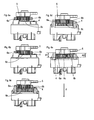
- Fig. 6a to 6e show successively the mounting phases in the assembly of a populated planetary carrier 5 in the ring gear 4 of the planetary gear.
- Fig. 6a shows the assembly just before the engagement of the first planetary gear 6a.
- the first planetary gear 6a is already engaged with the ring gear 4 and the planetary gear 6b is about to engage.
- Fig. 6c Also, the planet gear 6b is already in mesh with the ring gear 4 and the gear 6c is not yet engaged. Only in Fig. 6d are all three planet gears 6a, 6b, 6c engaged.
- Fig. 6a shows the assembly just before the engagement of the first planetary gear 6a.
- the first planetary gear 6a is already engaged with the ring gear 4 and the planetary gear 6b is about to engage.
- the planet gear 6b is already in mesh with the ring gear 4 and the gear 6c is not yet engaged. Only in Fig. 6d are all three planet gears 6a, 6b, 6c engaged.
Landscapes
- Engineering & Computer Science (AREA)
- General Engineering & Computer Science (AREA)
- Mechanical Engineering (AREA)
- Power Engineering (AREA)
- Retarders (AREA)
- Connection Of Motors, Electrical Generators, Mechanical Devices, And The Like (AREA)
Description
- Die Erfindung betrifft einen Stellantrieb, bestehend aus einem Elektromotor und einem Planetengetriebe, umfassend ein Hohlrad, einen Planetenträger und mehrere auf dem Planetenträger gelagerte Planetenräder, wobei die Planetenräder im Bereich ihrer Außenverzahnung jeweils eine in Fügerichtung vorangehende Stirnfläche aufweisen und das Hohlrad im Bereich seiner Innenverzahnung mehrere den Planetenrädern zugeordneten Winkelbereiche seiner der Fügerichtung gegengerichteten Stirnseite in einer definierten Winkelstellung des Planetenträgers zum Hohlrad aufweist, wobei sich der axiale Abstand zwischen der Stirnfläche des ersten Planetenrades und dem ihm zugeordneten ersten Winkelbereich des Hohlrades von dem axialen Abstand zwischen der Stirnfläche des zweiten Planetenrades und dem ihm zugeordneten zweiten Winkelbereich des Hohlrades unterscheidet.
- Aus der
EP 0 667 279 A1 ist ein Stellantrieb, bestehend aus einem Elektromotor und einem Planetengetriebe bekannt. Bei diesem Stellantrieb weisen die Planetenräder die gleiche Dicke auf, sind in einer Ebene angeordnet und das Hohlrad endet durchgängig in einer zu dieser Ebene parallelen Ebene. Durch diese Geometrie treffen bei der Montage die Stirnseiten der Planetenräder gleichzeitig am Hohlrad ein, wodurch es zu Fügeproblemen kommen kann. - Aus der
US 2006/142114 A1 ist ein einstufiges Planetengetriebe bekannt, bei dem Sich der axiale Abstand zwischen der Stirnfläche des ersten Planetenrades und dem ihm zugeordneten ersten Winkelbereich des Hohlrades von dem axialen Abstand zwischen der Stirnfläche des zweiten Planetenrades und dem ihm zugeordneten zweiten Winkelbereich des Hohlrades unterscheidet. Durch diese Maßnahme lassen sich zumindest die ersten beiden Planetenräder einfacher fügen. - Die
US 5,800,305 A , sowie dieUS 2005/192151 A1 zeigen mehrstufige Planetengetriebe, bei denen ebenfalls die Stirnseiten der Planetenräder unterschiedliche axiale Abstände zum Hohlrad aufweisen. - Aus der
DE 197 29 988 C1 ist ein gattungsgemäßer Stellantrieb beschrieben, worin die Winkelbereiche der der Fügerichtung entgegengerichteten Stirnseite in einer einzigen Ebene angeordnet sind und die in Fügerichtung vorangehenden Stirnseiten der Planetenräder, ebenso in einer einzigen Ebene angeordnet sind, so dass die einzelnen Abstände zwischen den Stirnseiten der Planetenräder und den Winkelbereichen des Hohlrades in jedem Montageschritt und auch in der Endmontageposition gleich sind. Problematisch ist diese geometrische Anordnung in dem Moment der Montage, in dem die Verzahnung der drei Planetenräder gleichzeitig mit der Verzahnung des Hohlrades in Eingriff kommt. Hierbei kommt es häufig zu Fügeproblemen, weil die Winkelposition der Planetenräder untereinander und zum Hohlrad sich nicht automatisch korrekt ausrichten. Dies führt mindestens zu einer Verringerung der Montagegeschwindigkeit. Es kann aber auch zu Beschädigungen der Verzahnung kommen. - Aufgabe der vorliegenden Erfindung ist es daher bei einem gattungsgemäßen Stellantrieb dafür zu sorgen, dass eine wirtschaftliche und zeitlich entkoppelte einfache und schnelle Montage der drei Planetenräder im Hohlrad möglich ist, ohne dadurch den Herstellaufwand zu erhöhen, wobei nur geringe Änderungen an bestehenden Formen nötig sind.
- Diese Aufgabe wird erfindungsgemäß dadurch gelöst, dass keine der Winkelbereiche der der Fügerichtung entgegengerichteten Stirnseite des Hohlrades Teil einer Ebene ist zu der eine der anderen Winkelbereiche gehört, wobei die Ebenen parallel zueinander und rechtwinklig zur Symmetrieachse des Stellantriebs ausgerichtet sind. Durch diese Maßnahme wird erreicht, dass die einzelnen Planetenräder zeitlich unabhängig voneinander in den montagekritischen Verzahnungsbereich des Hohlrades gelangen, so dass eine leichtere Selbstausrichtung der Planetenräder möglich ist. Dies erhöht die Montagegeschwindigkeit und verringert die Fehlerhäufigkeit bei der Montage. Die Erfindung ist auf Planetengetriebe mit zwei oder mehr Planetenrädern in der gleichen Getriebestufe einsetzbar.
- Weiterbildungen der Erfindungen werden in den Unteransprüchen dargestellt. Bei Verwendung von drei Planetenrädern in der gleichen Getriebestufe ist vorgesehen dass der axiale Abstand zwischen der Stirnfläche des zweiten Planetenrades und dem ihm zugeordneten zweiten Winkelbereich des Hohlrades sich von dem axialen Abstand zwischen der Stirnfläche des dritten Planetenrades und dem ihm zugeordneten dritten Winkelbereich des Hohlrades und dem axialen Abstand zwischen der Stirnfläche des ersten Planetenrades und dem ihm zugeordneten ersten Winkelbereich des Hohlrades unterscheidet.
- Um die genannte Aufgabe sicher zu lösen ist es wichtig, dass die Unterschiede in den Abständen größer sind als die durch die unvermeidbaren Toleranzen möglichen axialen Verlagerungen der Eingriffskanten der Planetenräder und des Hohlrads, so dass bei der Montage der Planetenräder jeweils nur ein Planetenrad gleichzeitig den Beginn eines Eingriffsbereichs zwischen Planetenrad und Hohlrad erreichen kann. Üblicherweise können bei der Montage Winkelungenauigkeiten auftreten, weiter weisen Getriebe notwendigerweise ein geringen Spiel auf. Auch Herstelltoleranzen sind immer gegeben. Diese Einflüsse summieren sich zu einem berechenbaren Maß, das unbedingt eingehalten werden muss um die genannten Vorteile zu erreichen.
- Bei einer ersten (nicht beanspruchten) Alternative ist vorgesehen, dass die Planetenräder in axialer Richtung unterschiedliche Dicke aufweisen. Damit lässt sich die zeitliche Entkopplung bei der Montage erreichen. Nachteilig ist jedoch, dass unterschiedliche Einzelteile notwendig sind. Zudem könnte diese Lösung bei höheren Drehzahlen zu unerwünschten Geräuschen führen, deshalb wird diese Lösung nicht bevorzugt.
- Bei einer zweiten (nicht beanspruchten) Alternative ist vorgesehen, dass die Planetenräder in unterschiedlicher axialer Anordnung auf dem Planetenträger gelagert sind, wobei die Planetenräder identisch geformt sind. Auch mit dieser Lösung wird eine zeitliche Entkopplung des Eingriffszeitpunktes der Planetenräder erreicht. Hier ist je nach Aufbau des Planetenträgers nur ein Bauteil zu ändern.
- Problematisch bei den genannten beiden Alternativen ist auch die axiale Lagerung der Planetenträger im eingebauten Zustand. Diese muss auf dem Planetenträger selbst erfolgen, weil eine Anlagefläche im Hohlrad oder Getriebegehäuse entweder ein zusätzliches mitlaufendes Bauteil erforderlich machen würde oder bei zumindest zwei Planetenrädern ein großes Axialspiel in Kauf genommen werden müsste.
- Um die zweite Alternative zu realisieren wird vorgeschlagen, dass der Planetenträger Achszapfen aufweist, auf denen die Planetenräder radial gelagert sind und dass der Planetenträger axiale Anlaufringflächen aufweist an denen die Planetenräder axial gelagert sind, wobei die Anlaufringflächen unterschiedlich weit axial vorspringen. Bei einer einstückigen Ausbildung des Planetenträgers z.B. bei einem aus Kunststoff urgeformten Planetenträger lassen sich diese Anlaufringflächen problemlos herstellen. Bei einem aus mehreren Einzelteilen zusammengesetzten Planetenträger können die Vorteile gegenüber der ersten Alternative verloren gehen.
- Bei einer dritten (nicht beanspruchten) Alternative ist vorgesehen, dass die Stirnflächen der Planetenräder im montierten Zustand in unterschiedlicher axialer Lage angeordnet sind, wobei die Planetenräder die gleiche Verzahnungsbreite aufweisen und Anlaufringflächen beiderseits der Verzahnung der Planetenräder unterschiedlich weit axial vorspringen. Die jeweiligen Zahnkränze sind mit Naben einstückig ausgebildet oder durch Presspassung verbunden, wobei die Zahnkränze gegenüber der Nabe unterschiedlich weit axial versetzt angeordnet sind. Bei montierten Planetenrädern können Gleichteile verwendet werden und die gewünschte Geometrie lediglich durch unterschiedliche Einpresshöhe erreicht werden.
- Bei der dritten Alternative können das erste und dritte Planetenrad identisch ausgebildet sein, wobei sie lediglich um 180° verdreht montiert werden, um einen unterschiedlichen Axialversatz zu erreichen. Das zweite Planetenrad unterscheidet sich vom ersten und dritten Planetenrad, kann jedoch zu einer Mittenebene symmetrisch geformt sein und somit in beiden möglichen Ausrichtungen montiert werden.
- Besonders vorteilhaft ist es, das Hohlrad mit dem Lagerschild einstückig aus einem Kunststoffmaterial herzustellen.
- Die Erfindung wird nachfolgend anhand der Zeichnung näher erläutert. Es zeigen:
-
Fig. 1 eine Schnittansicht durch einen Stellantrieb, -
Fig. 2 einen montierten Planetenträger mit unterschiedlich breiten Planetenrädern, -
Fig. 3a einen Steg eines Planetenträgers mit unterschiedlich angeordneten Anlaufringflächen, -
Fig. 3b einen montierten Planetenträger gemäßFig. 3a , -
Fig. 4 eine stilisierte Schnittansicht mit Planetenrädern in unterschiedlicher axialer Anordnung, -
Fig. 5a eine räumliche Darstellung eines Hohlrades gemäß der Erfindung, -
Fig. 5b eine räumliche Darstellung des Hohlrades ausFig. 5a aus anderer Perspektive, -
Fig. 5c einen montierten Planetenträger gemäß der Erfindung, -
Fig. 6a eine Teilschnittansicht eines Planetengetriebes vor Montage des Planetenträgers, -
Fig. 6b eine Teilschnittansicht des Planetengetriebes in einer ersten Montagephase, -
Fig. 6c eine Teilschnittansicht des Planetengetriebes in einer zweiten Montagephase, -
Fig. 6d eine Teilschnittansicht des Planetengetriebes in einer dritten Montagephase und -
Fig. 6e eine Teilschnittansicht des Planetengetriebes in der fertig montierten Position. - Die folgenden Figuren zeigen jeweils drei Planetenräder je Getriebestufe und auch jeweils nur eine Getriebestufe, die Erfindung umfasst jedoch auch Planetengetriebe mit zwei, vier oder mehr Planetenrädern je Getriebestufe und auch mehrstufige Planetengetriebe. Weiter können die Stellantriebe zusätzliche Getriebestufen anderer Getriebearten, wie Stirnrad-, Schnecken- oder Kegelgetriebe umfassen und Motorachse muss nicht mit der Planetengetriebeachse fluchten.
-
Fig. 1 zeigt eine Schnittansicht durch einen Stellantrieb 1, bestehend aus einem Elektromotor 2 und einem Planetengetriebe 3. Der Elektromotor ist ein Kommutatormotor, mit einem Gehäusetopf 18, einem bewickelten Rotor 19 mit einem Kommutator 20 und einer Bürstenbrücke, die als Lagerschild 13 dient. Das Planetengetriebe umfasst ein Hohlrad 4, ein Sonnenrad 14, einen Planetenträger 5 und Planetenräder 6a, 6b, 6c. Der Ausgang des Planetengetriebes 3 ist mit einem Zahnstangengetriebe getrieblich verbunden. Der Stellantrieb dient als AGR-Antrieb. -
Fig. 2 zeigt einen montierten Planetenträger 5, wobei dieser mit drei unterschiedlich breiten Planetenrädern 6a, 6b, 6c bestückt ist. Die Stirnseiten 7a, 7b, 7c der Planetenräder 6a, 6b, 6c liegen in unterschiedlichen zueinander parallelen Ebenen, so dass bei der Montage des bestückten Planetenträgers 5 in Fügerichtung F zunächst das Planetenrad 6a, dann 6b und schließlich 6c in Eingriff mit der Verzahnung des Hohlrades kommen. -
Fig. 3a zeigt einen alternativen Planetenträger 5 (ohne Achszapfen 10), wobei der Planetenträger Anlaufringflächen 11a, 11b, 11c aufweist, die Bestandteil unterschiedlicher paralleler Ebenen sind, also unterschiedlich weit aus der Ebene des Planetenträgers (Steg) vorspringen. InFig. 3b ist der gleiche Planetenträger 5 mit Planetenrädern 6a, 6b, 6c bestückt. Die Planetenräder weisen Anlaufringflächen 16a, 16b, 16c auf, die dem Planetenträger abgewandt sind. Auf der gegenüberliegenden Seite der Planetenräder 6a, 6b, 6c (hier verdeckt) befinden sich Anlaufringflächen 15a, 15b, 15c, die den Anlaufringflächen 11a, 11b, 11c zugewandt sind. Die Anlaufringflächen 15a, 15b, 15c und 16a, 16b, 16c bilden die Stirnflächen der Planetenradnaben 17a, 17b, 17c. Die Breite der Planetenräder ist hier gleich groß und die Planetenräder 6a, 6b, 6c identisch ausgebildet. - Eine weitere Alternative ist in
Fig. 4 stilisiert dargestellt. Ein Planetenträger 5 weist Achszapfen 10a, 10b, 10c auf, auf denen Planetenräder 6a, 6b, 6c drehbar gelagert sind. Die Planetenräder besitzen Naben 17a, 17b, 17c, deren Stirnflächen dem Planetenträger 5 als Anlaufringflächen 15a, 15b, 15c zugewandt sind und deren gegenüberliegende Stirnflächen dem Planetenträger 5 abgewandt sind und als Anlaufringflächen 16a, 16b, 16c dienen. Die Anlaufringflächen 15a, 15b, 15c sowie 16a, 16b, 16c springen unterschiedlich weit vor und begrenzen den Bauraum der Planetenräder 6a, 6b, 6c. Eine Axiallagerscheibe, die z.B. im Hohlrad angeordnet sein kann oder auch Bestandteil des Planetenträgers sein kann dient als axiale Abstützung und Begrenzung für die Planetenräder 6a, 6b, 6c. Die Planetenräder 6a, 6b, 6c können mit ihrer Nabe 17a, 17b, 17c einstückig als Kunststoffspritzgussteil ausgebildet sein. In diesem Fall sind zumindest zwei unterschiedliche Werkzeugnester erforderlich. Planetenrad 6a ist durch Drehen um 180° mit Planetenrad 6c identisch. Das Planetenrad 6b unterscheidet sich von den Planetenrädern 6a und 6c, kann aber symmetrisch ausgebildet sein. Es ist auch denkbar, dass die Nabe in die Planetenräder montiert wird und z.B. durch eine Presspassung fixiert ist. Bei dieser Variante können Gleichteile verwendet werden, die nur noch unterschiedlich montiert werden müssen. -
Fig. 5a und 5b zeigen ein Hohlrad 4 aus unterschiedlicher Perspektive. Dieses Hohlrad zeigt die Ausführungsform der Erfindung. Hier sind die Planetenräder identisch ausgebildet und die Stirnseite 9 des Hohlrades ist in drei Bereiche 8a, 8b, 8c unterteilt, die jeweils ca. 120° des Umfangs einnehmen. Die Bereiche 8a, 8b, 8c springen unterschiedlich weit aus der Stirnseite 9 des Hohlrads 4 hervor. - Die
Fig. 6a bis 6e zeigen nacheinander die Montagephasen, bei der Montage eines Bestückten Planetenträgers 5 in das Hohlrad 4 des Planetengetriebes.Fig. 6a zeigt die Baugruppe kurz vor dem Eingriff des ersten Planetenrades 6a. InFig. 6b ist das erste Planetenrad 6a bereits mit dem Hohlrad 4 in Eingriff und das Planetenrad 6b befindet sich kurz vor dem Eingriff. InFig. 6c ist auch das Planetenrad 6b bereits in Eingriff mit dem Hohlrad 4 und das Zahnrad 6c ist noch nicht in Eingriff. Erst inFig. 6d befinden sich alle drei Planetenräder 6a, 6b, 6c in Eingriff. InFig. 6d ist die Endposition erreicht, in der die Stirnseiten der Planetenräder 7a, 7b, 7c in Fügerichtung unterschiedliche Abstände A1, A2, A3 zu den jeweiligen Winkelbereichen 8a, 8b, 8c der Stirnseite 9 des Hohlrades aufweisen. -
- 1
- Stellantrieb
- 2
- Elektromotor
- 3
- Planetengetriebe
- 4
- Hohlrad
- 5
- Planetenträger
- 6
- Planetenräder
- 7
- Stirnfläche
- 8
- Winkelbereich
- 9
- Stirnseite
- 10
- Achszapfen
- 11
- Anlaufringfläche des Planetenträgers
- 12
- Ebene
- 13
- Lagerschild
- 14
- Sonnenrad
- 15
- Anlaufringfläche der Planetenräder (Planetenträger zugewandt)
- 16
- Anlaufringfläche der Planetenräder (Planetenträger abgewandt)
- 17
- Nabe
- 18
- Gehäusetopf
- 19
- Rotor
- 20
- Kommutator
- 21
- Axiallagerscheibe
Claims (4)
- Stellantrieb (1), bestehend aus einem Elektromotor (2) und einem Planetengetriebe (3), umfassend ein Hohlrad (4), einen Planetenträger (5) und mehrere auf dem Planetenträger (5) gelagerte Planetenräder (6a, 6b, 6c), wobei die Planetenräder (6a, 6b, 6c) im Bereich ihrer Außenverzahnung jeweils eine in Fügerichtung (F) vorangehende Stirnfläche (7a, 7b, 7c) aufweisen und das Hohlrad (4) im Bereich seiner Innenverzahnung mehrere den Planetenrädern zugeordneten Winkelbereiche (8a, 8b, 8c) seiner der Fügerichtung (F) gegengerichteten Stirnseite (9) in einer definierten Winkelstellung des Planetenträgers (5) zum Hohlrad (4) aufweist, dadurch gekennzeichnet, dass sich der axiale Abstand (A1) zwischen der Stirnfläche (7a) des ersten Planetenrades (6a) und dem ihm zugeordneten ersten Winkelbereich (8a) des Hohlrades (4) von dem axialen Abstand (A2) zwischen der Stirnfläche (7b) des zweiten Planetenrades (6b) und dem ihm zugeordneten zweiten Winkelbereich (8b) des Hohlrades (4) unterscheidet, und dass keine der Winkelbereiche (8a, 8b, 8c) der der Fügerichtung (F) entgegengerichteten Stirnseite (9) des Hohlrades (4) Teil einer Ebene (12a, 12b, 12c) ist zu der eine der anderen Winkelbereiche (8a, 8b, 8c) gehört, wobei die Ebenen (12a, 12b, 12c) parallel zueinander und rechtwinklig zur Symmetrieachse des Stellantriebs ausgerichtet sind.
- Stellantrieb nach Anspruch 1, dadurch gekennzeichnet, dass der axiale Abstand (A2) zwischen der Stirnfläche (7b) des zweiten Planetenrades (6b) und dem ihm zugeordneten zweiten Winkelbereich (8b) des Hohlrades (4) sich von dem axialen Abstand (A3) zwischen der Stirnfläche (7c) des dritten Planetenrades (6c) und dem ihm zugeordneten dritten Winkelbereich (8c) des Hohlrades (4) und dem axialen Abstand (A1) zwischen der Stirnfläche (7a) des ersten Planetenrades (6a) und dem ihm zugeordneten ersten Winkelbereich (8a) des Hohlrades (4) unterscheidet.
- Stellantrieb nach Anspruch 1 oder 2, dadurch gekennzeichnet, dass die Unterschiede in den Abständen (A1, A2, A3) größer sind als die durch die unvermeidbaren Toleranzen möglichen axialen Verlagerungen der Eingriffskanten der Planetenräder und des Hohlrads, so dass bei der Montage der Planetenräder (6a, 6b, 6c) jeweils nur ein Planetenrad (6a, 6b, 6c) gleichzeitig den Beginn eines Eingriffsbereichs zwischen Planetenrad (6a, 6b, 6c) und Hohlrad (4) erreichen kann.
- Stellantrieb nach zumindest einem der vorangehenden Ansprüche, dadurch gekennzeichnet, dass das Hohlrad (4) einstückig mit einem Lagerschilds (13) des Elektromotors (2) ist und aus Kunststoffmaterial besteht.
Applications Claiming Priority (1)
| Application Number | Priority Date | Filing Date | Title |
|---|---|---|---|
| DE102008053571A DE102008053571B4 (de) | 2008-10-15 | 2008-10-15 | Stellantrieb mit einem Elektromotor und einem Planetengetriebe |
Publications (3)
| Publication Number | Publication Date |
|---|---|
| EP2177789A2 EP2177789A2 (de) | 2010-04-21 |
| EP2177789A3 EP2177789A3 (de) | 2010-06-02 |
| EP2177789B1 true EP2177789B1 (de) | 2011-12-28 |
Family
ID=41528778
Family Applications (1)
| Application Number | Title | Priority Date | Filing Date |
|---|---|---|---|
| EP09012174A Not-in-force EP2177789B1 (de) | 2008-10-15 | 2009-09-25 | Stellantrieb mit einem Elektromotor und einem Planetengetriebe |
Country Status (5)
| Country | Link |
|---|---|
| US (1) | US8142321B2 (de) |
| EP (1) | EP2177789B1 (de) |
| AT (1) | ATE539286T1 (de) |
| DE (1) | DE102008053571B4 (de) |
| ES (1) | ES2378266T3 (de) |
Cited By (2)
| Publication number | Priority date | Publication date | Assignee | Title |
|---|---|---|---|---|
| DE102016203003A1 (de) | 2016-02-25 | 2017-08-31 | Bühler Motor GmbH | Planetengetriebe |
| WO2023232435A1 (de) * | 2022-05-30 | 2023-12-07 | Robert Bosch Gmbh | Antriebseinheit für eine betätigungseinrichtung eines bremssystems, betätigungseinrichtung für ein bremssystem, bremssystem |
Families Citing this family (11)
| Publication number | Priority date | Publication date | Assignee | Title |
|---|---|---|---|---|
| USD783684S1 (en) * | 2013-09-16 | 2017-04-11 | Eaton Corporation | Externally mounted plenum for limited slip differential |
| USD741916S1 (en) * | 2013-09-16 | 2015-10-27 | Eaton Corporation | Differential having externally mounted plenum |
| EP2913561B1 (de) * | 2014-02-26 | 2016-07-06 | IMS Gear GmbH | Motor-Planetengetriebe-Anordnung und Verfahren zum Verbinden eines Motors mit einem Planetengetriebe zur Herstellung einer Motor-Planetengetriebe-Anordnung |
| DE102014217396B4 (de) * | 2014-09-01 | 2016-09-15 | Schaeffler Technologies AG & Co. KG | Belastungsoptimiertes asymmetrisches Planetenträgerdesign |
| US10294634B2 (en) | 2014-10-01 | 2019-05-21 | Caterpillar Inc. | Rear entry electric drive motor module |
| CN105351494A (zh) * | 2015-12-03 | 2016-02-24 | 天津市津达执行器有限公司 | 一种双级行星执行器 |
| DE102016115045B4 (de) * | 2016-08-12 | 2022-03-31 | Bühler Motor GmbH | Gehäuse für eine Motor-Getriebeeinheit und Herstellungsverfahren |
| EP3633237A1 (de) * | 2018-10-02 | 2020-04-08 | Continental Automotive GmbH | Getriebe, insbesondere kleingetriebe für einen elektrokleinmotor und verfahren zur montage eines getriebes, insbesondere eines kleingetriebes |
| DE102019212345B4 (de) * | 2019-08-19 | 2024-02-08 | Robert Bosch Gmbh | Elektromechanisch antreibbarer Bremsdruckerzeuger |
| US11454314B2 (en) * | 2020-09-08 | 2022-09-27 | Fairfield Manufacturing Company, Inc. | Planetary gearbox with structural bearing and bushing support |
| DE102021209122A1 (de) | 2021-08-19 | 2023-02-23 | Robert Bosch Gesellschaft mit beschränkter Haftung | Antriebseinrichtung, Druckerzeuger für eine Bremsanlage |
Family Cites Families (10)
| Publication number | Priority date | Publication date | Assignee | Title |
|---|---|---|---|---|
| DE2313698A1 (de) * | 1973-03-20 | 1974-10-03 | Gruner Klaus Feinwerktech | Antriebsvorrichtung fuer ventile und dergleichen |
| JP3028905B2 (ja) * | 1994-01-31 | 2000-04-04 | アイシン精機株式会社 | 後輪操舵アクチュエ−タ |
| US5800305A (en) * | 1995-12-29 | 1998-09-01 | Koon-Woo Kang | Reduction gear with coaxial input and output shafts and combining planetary and nonplanetary gearing |
| DE19711423C1 (de) * | 1997-03-19 | 1998-09-24 | Buehler Gmbh Nachf Geb | Planetenträger für ein Planetengetriebe |
| DE19729988C1 (de) * | 1997-07-12 | 1998-08-13 | Buehler Gmbh Nachf Geb | Formschlüssige Verbindung zwischen einem aus Kunststoff bestehenden Getriebegehäuseteil und einer Adapterplatte eines Elektromotors |
| DE19829532A1 (de) * | 1998-07-02 | 2000-01-05 | Zahnradfabrik Friedrichshafen | Hebezeugantrieb |
| JP3560947B2 (ja) * | 2001-11-06 | 2004-09-02 | 株式会社日立製作所 | 回転電機 |
| DE10300641A1 (de) * | 2003-01-09 | 2004-07-22 | Siemens Ag | Stellantrieb |
| EP1588074B1 (de) * | 2003-01-27 | 2006-07-05 | The Timken Company | Planetengetriebesysteme |
| US6986726B2 (en) * | 2004-02-26 | 2006-01-17 | Ford Global Technologies, Llc | Planet pinion carrier assembly for Ravigneaux gearset |
-
2008
- 2008-10-15 DE DE102008053571A patent/DE102008053571B4/de not_active Expired - Fee Related
-
2009
- 2009-09-25 EP EP09012174A patent/EP2177789B1/de not_active Not-in-force
- 2009-09-25 ES ES09012174T patent/ES2378266T3/es active Active
- 2009-09-25 AT AT09012174T patent/ATE539286T1/de active
- 2009-10-14 US US12/588,396 patent/US8142321B2/en not_active Expired - Fee Related
Cited By (2)
| Publication number | Priority date | Publication date | Assignee | Title |
|---|---|---|---|---|
| DE102016203003A1 (de) | 2016-02-25 | 2017-08-31 | Bühler Motor GmbH | Planetengetriebe |
| WO2023232435A1 (de) * | 2022-05-30 | 2023-12-07 | Robert Bosch Gmbh | Antriebseinheit für eine betätigungseinrichtung eines bremssystems, betätigungseinrichtung für ein bremssystem, bremssystem |
Also Published As
| Publication number | Publication date |
|---|---|
| EP2177789A2 (de) | 2010-04-21 |
| US20100093478A1 (en) | 2010-04-15 |
| EP2177789A3 (de) | 2010-06-02 |
| US8142321B2 (en) | 2012-03-27 |
| ATE539286T1 (de) | 2012-01-15 |
| ES2378266T3 (es) | 2012-04-10 |
| DE102008053571A1 (de) | 2010-04-29 |
| DE102008053571B4 (de) | 2010-07-22 |
Similar Documents
| Publication | Publication Date | Title |
|---|---|---|
| EP2177789A2 (de) | Stellantrieb mit einem Elektromotor und einem Planetengetriebe | |
| DE102004013009B4 (de) | Antrieb für eine Verstelleinrichtung innerhalb eines Fahrzeuges, insbesondere eine Sitzverstelleinrichtung innerhalb eines Kraftfahrzeuges und Verfahren zur Herstellung eines solchen Antriebs | |
| EP1266153B1 (de) | Getriebebaukasten | |
| EP3283788B1 (de) | Getriebemotor und verfahren zur montage eines getriebemotors | |
| EP2730807B1 (de) | Planetengetriebe mit mehreren Getriebestufen | |
| DE102016118336A1 (de) | Antriebsmechanismus | |
| DE2231709A1 (de) | Getriebeanordnung | |
| WO2012041551A1 (de) | Planetengetriebe, planetendifferenzial und getriebe mit dem planetendifferenzial | |
| WO2014019742A1 (de) | Getriebekombination mit einem planetendifferenzial nach art eines wildhaber-novikov-stirnraddifferenzials | |
| DE102012222602A1 (de) | Elektrische Maschine | |
| EP0794358A2 (de) | Elektromotorischer Möbelantrieb | |
| EP1989096A1 (de) | Schraubradgetriebe für zahnstangenlenkung | |
| EP2913561A1 (de) | Motor-Planetengetriebe-Anordnung und Verfahren zum Verbinden eines Motors mit einem Planetengetriebe zur Herstellung einer Motor-Planetengetriebe-Anordnung | |
| EP3033545B1 (de) | Getriebe mit einem ritzel und einem rad | |
| EP0627575B1 (de) | Wolfrom-Planetenzahnradgetriebe mit axial in zwei unterschiedlich verzahnte Bereiche aufgeteilten Planetenrädern | |
| DE10308726A1 (de) | Lenkantrieb für Flurförderzeuge | |
| EP3513099B1 (de) | Getriebeseitiges motorlagerschild | |
| EP1811123B1 (de) | Rohrmotor-Antriebsbaugruppe | |
| WO2011098182A1 (de) | Planetengetriebe und verwendung desselben | |
| DE1450768B1 (de) | Getriebe für geringe Leistungen | |
| DE102012213393A1 (de) | Gehäusekonstruktion für ein Wildhaber-Novikov-Stirnraddifferenzial, Planetengetriebe und Getriebekombination mit einem Planetendifferenzial | |
| DE102005017160B4 (de) | Getriebe mit einem in Zahneingriff stehenden Antriebsteil und Abtriebsteil, das in einer definierten Drehendstellung stoppt | |
| DE102020002698A1 (de) | Getriebe mit einem eine Verzahnung aufweisenden Rad und jeweils eine Ritzelverzahnung aufweisenden Ritzeln | |
| DE102012202926A1 (de) | Getriebe für ein Einzelradtriebwerk eines Flurförderzeugs, sowie Einzelradtriebwerk | |
| DE2452738C3 (de) | Zeitschaltgerät, insbesondere digitale Herdschaltuhr |
Legal Events
| Date | Code | Title | Description |
|---|---|---|---|
| PUAI | Public reference made under article 153(3) epc to a published international application that has entered the european phase |
Free format text: ORIGINAL CODE: 0009012 |
|
| AK | Designated contracting states |
Kind code of ref document: A2 Designated state(s): AT BE BG CH CY CZ DE DK EE ES FI FR GB GR HR HU IE IS IT LI LT LU LV MC MK MT NL NO PL PT RO SE SI SK SM TR |
|
| AX | Request for extension of the european patent |
Extension state: AL BA RS |
|
| PUAL | Search report despatched |
Free format text: ORIGINAL CODE: 0009013 |
|
| AK | Designated contracting states |
Kind code of ref document: A3 Designated state(s): AT BE BG CH CY CZ DE DK EE ES FI FR GB GR HR HU IE IS IT LI LT LU LV MC MK MT NL NO PL PT RO SE SI SK SM TR |
|
| AX | Request for extension of the european patent |
Extension state: AL BA RS |
|
| RIC1 | Information provided on ipc code assigned before grant |
Ipc: F16H 57/08 20060101AFI20100126BHEP Ipc: F16H 57/02 20060101ALN20100429BHEP Ipc: H02K 7/116 20060101ALI20100429BHEP |
|
| 17P | Request for examination filed |
Effective date: 20100927 |
|
| RIC1 | Information provided on ipc code assigned before grant |
Ipc: F16H 57/02 20060101ALN20110418BHEP Ipc: F16H 57/08 20060101AFI20110418BHEP Ipc: H02K 7/116 20060101ALI20110418BHEP |
|
| GRAP | Despatch of communication of intention to grant a patent |
Free format text: ORIGINAL CODE: EPIDOSNIGR1 |
|
| GRAS | Grant fee paid |
Free format text: ORIGINAL CODE: EPIDOSNIGR3 |
|
| GRAA | (expected) grant |
Free format text: ORIGINAL CODE: 0009210 |
|
| AK | Designated contracting states |
Kind code of ref document: B1 Designated state(s): AT BE BG CH CY CZ DE DK EE ES FI FR GB GR HR HU IE IS IT LI LT LU LV MC MK MT NL NO PL PT RO SE SI SK SM TR |
|
| REG | Reference to a national code |
Ref country code: GB Ref legal event code: FG4D Free format text: NOT ENGLISH |
|
| REG | Reference to a national code |
Ref country code: CH Ref legal event code: EP |
|
| REG | Reference to a national code |
Ref country code: AT Ref legal event code: REF Ref document number: 539286 Country of ref document: AT Kind code of ref document: T Effective date: 20120115 |
|
| REG | Reference to a national code |
Ref country code: IE Ref legal event code: FG4D |
|
| REG | Reference to a national code |
Ref country code: DE Ref legal event code: R096 Ref document number: 502009002279 Country of ref document: DE Effective date: 20120308 |
|
| REG | Reference to a national code |
Ref country code: ES Ref legal event code: FG2A Ref document number: 2378266 Country of ref document: ES Kind code of ref document: T3 Effective date: 20120410 |
|
| REG | Reference to a national code |
Ref country code: NL Ref legal event code: VDEP Effective date: 20111228 |
|
| PG25 | Lapsed in a contracting state [announced via postgrant information from national office to epo] |
Ref country code: LT Free format text: LAPSE BECAUSE OF FAILURE TO SUBMIT A TRANSLATION OF THE DESCRIPTION OR TO PAY THE FEE WITHIN THE PRESCRIBED TIME-LIMIT Effective date: 20111228 Ref country code: NO Free format text: LAPSE BECAUSE OF FAILURE TO SUBMIT A TRANSLATION OF THE DESCRIPTION OR TO PAY THE FEE WITHIN THE PRESCRIBED TIME-LIMIT Effective date: 20120328 |
|
| LTIE | Lt: invalidation of european patent or patent extension |
Effective date: 20111228 |
|
| PG25 | Lapsed in a contracting state [announced via postgrant information from national office to epo] |
Ref country code: GR Free format text: LAPSE BECAUSE OF FAILURE TO SUBMIT A TRANSLATION OF THE DESCRIPTION OR TO PAY THE FEE WITHIN THE PRESCRIBED TIME-LIMIT Effective date: 20120329 Ref country code: SI Free format text: LAPSE BECAUSE OF FAILURE TO SUBMIT A TRANSLATION OF THE DESCRIPTION OR TO PAY THE FEE WITHIN THE PRESCRIBED TIME-LIMIT Effective date: 20111228 Ref country code: LV Free format text: LAPSE BECAUSE OF FAILURE TO SUBMIT A TRANSLATION OF THE DESCRIPTION OR TO PAY THE FEE WITHIN THE PRESCRIBED TIME-LIMIT Effective date: 20111228 Ref country code: SE Free format text: LAPSE BECAUSE OF FAILURE TO SUBMIT A TRANSLATION OF THE DESCRIPTION OR TO PAY THE FEE WITHIN THE PRESCRIBED TIME-LIMIT Effective date: 20111228 Ref country code: HR Free format text: LAPSE BECAUSE OF FAILURE TO SUBMIT A TRANSLATION OF THE DESCRIPTION OR TO PAY THE FEE WITHIN THE PRESCRIBED TIME-LIMIT Effective date: 20111228 |
|
| PG25 | Lapsed in a contracting state [announced via postgrant information from national office to epo] |
Ref country code: CY Free format text: LAPSE BECAUSE OF FAILURE TO SUBMIT A TRANSLATION OF THE DESCRIPTION OR TO PAY THE FEE WITHIN THE PRESCRIBED TIME-LIMIT Effective date: 20111228 |
|
| REG | Reference to a national code |
Ref country code: IE Ref legal event code: FD4D |
|
| PG25 | Lapsed in a contracting state [announced via postgrant information from national office to epo] |
Ref country code: NL Free format text: LAPSE BECAUSE OF FAILURE TO SUBMIT A TRANSLATION OF THE DESCRIPTION OR TO PAY THE FEE WITHIN THE PRESCRIBED TIME-LIMIT Effective date: 20111228 Ref country code: EE Free format text: LAPSE BECAUSE OF FAILURE TO SUBMIT A TRANSLATION OF THE DESCRIPTION OR TO PAY THE FEE WITHIN THE PRESCRIBED TIME-LIMIT Effective date: 20111228 Ref country code: IS Free format text: LAPSE BECAUSE OF FAILURE TO SUBMIT A TRANSLATION OF THE DESCRIPTION OR TO PAY THE FEE WITHIN THE PRESCRIBED TIME-LIMIT Effective date: 20120428 Ref country code: IE Free format text: LAPSE BECAUSE OF FAILURE TO SUBMIT A TRANSLATION OF THE DESCRIPTION OR TO PAY THE FEE WITHIN THE PRESCRIBED TIME-LIMIT Effective date: 20111228 Ref country code: CZ Free format text: LAPSE BECAUSE OF FAILURE TO SUBMIT A TRANSLATION OF THE DESCRIPTION OR TO PAY THE FEE WITHIN THE PRESCRIBED TIME-LIMIT Effective date: 20111228 Ref country code: BG Free format text: LAPSE BECAUSE OF FAILURE TO SUBMIT A TRANSLATION OF THE DESCRIPTION OR TO PAY THE FEE WITHIN THE PRESCRIBED TIME-LIMIT Effective date: 20120328 Ref country code: SK Free format text: LAPSE BECAUSE OF FAILURE TO SUBMIT A TRANSLATION OF THE DESCRIPTION OR TO PAY THE FEE WITHIN THE PRESCRIBED TIME-LIMIT Effective date: 20111228 |
|
| PG25 | Lapsed in a contracting state [announced via postgrant information from national office to epo] |
Ref country code: PL Free format text: LAPSE BECAUSE OF FAILURE TO SUBMIT A TRANSLATION OF THE DESCRIPTION OR TO PAY THE FEE WITHIN THE PRESCRIBED TIME-LIMIT Effective date: 20111228 Ref country code: RO Free format text: LAPSE BECAUSE OF FAILURE TO SUBMIT A TRANSLATION OF THE DESCRIPTION OR TO PAY THE FEE WITHIN THE PRESCRIBED TIME-LIMIT Effective date: 20111228 Ref country code: PT Free format text: LAPSE BECAUSE OF FAILURE TO SUBMIT A TRANSLATION OF THE DESCRIPTION OR TO PAY THE FEE WITHIN THE PRESCRIBED TIME-LIMIT Effective date: 20120430 |
|
| PG25 | Lapsed in a contracting state [announced via postgrant information from national office to epo] |
Ref country code: DK Free format text: LAPSE BECAUSE OF FAILURE TO SUBMIT A TRANSLATION OF THE DESCRIPTION OR TO PAY THE FEE WITHIN THE PRESCRIBED TIME-LIMIT Effective date: 20111228 |
|
| PLBE | No opposition filed within time limit |
Free format text: ORIGINAL CODE: 0009261 |
|
| STAA | Information on the status of an ep patent application or granted ep patent |
Free format text: STATUS: NO OPPOSITION FILED WITHIN TIME LIMIT |
|
| 26N | No opposition filed |
Effective date: 20121001 |
|
| REG | Reference to a national code |
Ref country code: DE Ref legal event code: R097 Ref document number: 502009002279 Country of ref document: DE Effective date: 20121001 |
|
| BERE | Be: lapsed |
Owner name: BUHLER MOTOR G.M.B.H. Effective date: 20120930 |
|
| PG25 | Lapsed in a contracting state [announced via postgrant information from national office to epo] |
Ref country code: MC Free format text: LAPSE BECAUSE OF NON-PAYMENT OF DUE FEES Effective date: 20120930 |
|
| PG25 | Lapsed in a contracting state [announced via postgrant information from national office to epo] |
Ref country code: FI Free format text: LAPSE BECAUSE OF FAILURE TO SUBMIT A TRANSLATION OF THE DESCRIPTION OR TO PAY THE FEE WITHIN THE PRESCRIBED TIME-LIMIT Effective date: 20111228 |
|
| PG25 | Lapsed in a contracting state [announced via postgrant information from national office to epo] |
Ref country code: BE Free format text: LAPSE BECAUSE OF NON-PAYMENT OF DUE FEES Effective date: 20120930 Ref country code: DE Free format text: LAPSE BECAUSE OF NON-PAYMENT OF DUE FEES Effective date: 20130403 |
|
| REG | Reference to a national code |
Ref country code: DE Ref legal event code: R119 Ref document number: 502009002279 Country of ref document: DE Effective date: 20130403 |
|
| PG25 | Lapsed in a contracting state [announced via postgrant information from national office to epo] |
Ref country code: MT Free format text: LAPSE BECAUSE OF FAILURE TO SUBMIT A TRANSLATION OF THE DESCRIPTION OR TO PAY THE FEE WITHIN THE PRESCRIBED TIME-LIMIT Effective date: 20111228 |
|
| PG25 | Lapsed in a contracting state [announced via postgrant information from national office to epo] |
Ref country code: TR Free format text: LAPSE BECAUSE OF FAILURE TO SUBMIT A TRANSLATION OF THE DESCRIPTION OR TO PAY THE FEE WITHIN THE PRESCRIBED TIME-LIMIT Effective date: 20111228 |
|
| REG | Reference to a national code |
Ref country code: CH Ref legal event code: PL |
|
| PG25 | Lapsed in a contracting state [announced via postgrant information from national office to epo] |
Ref country code: LU Free format text: LAPSE BECAUSE OF NON-PAYMENT OF DUE FEES Effective date: 20120925 Ref country code: SM Free format text: LAPSE BECAUSE OF FAILURE TO SUBMIT A TRANSLATION OF THE DESCRIPTION OR TO PAY THE FEE WITHIN THE PRESCRIBED TIME-LIMIT Effective date: 20111228 |
|
| PG25 | Lapsed in a contracting state [announced via postgrant information from national office to epo] |
Ref country code: CH Free format text: LAPSE BECAUSE OF NON-PAYMENT OF DUE FEES Effective date: 20130930 Ref country code: HU Free format text: LAPSE BECAUSE OF FAILURE TO SUBMIT A TRANSLATION OF THE DESCRIPTION OR TO PAY THE FEE WITHIN THE PRESCRIBED TIME-LIMIT Effective date: 20090925 Ref country code: LI Free format text: LAPSE BECAUSE OF NON-PAYMENT OF DUE FEES Effective date: 20130930 |
|
| PG25 | Lapsed in a contracting state [announced via postgrant information from national office to epo] |
Ref country code: MK Free format text: LAPSE BECAUSE OF FAILURE TO SUBMIT A TRANSLATION OF THE DESCRIPTION OR TO PAY THE FEE WITHIN THE PRESCRIBED TIME-LIMIT Effective date: 20111228 |
|
| REG | Reference to a national code |
Ref country code: FR Ref legal event code: PLFP Year of fee payment: 8 |
|
| REG | Reference to a national code |
Ref country code: FR Ref legal event code: PLFP Year of fee payment: 9 |
|
| REG | Reference to a national code |
Ref country code: FR Ref legal event code: PLFP Year of fee payment: 10 |
|
| PGFP | Annual fee paid to national office [announced via postgrant information from national office to epo] |
Ref country code: IT Payment date: 20210906 Year of fee payment: 13 Ref country code: AT Payment date: 20210909 Year of fee payment: 13 Ref country code: FR Payment date: 20210908 Year of fee payment: 13 |
|
| PGFP | Annual fee paid to national office [announced via postgrant information from national office to epo] |
Ref country code: GB Payment date: 20210913 Year of fee payment: 13 |
|
| PGFP | Annual fee paid to national office [announced via postgrant information from national office to epo] |
Ref country code: ES Payment date: 20211004 Year of fee payment: 13 |
|
| REG | Reference to a national code |
Ref country code: AT Ref legal event code: MM01 Ref document number: 539286 Country of ref document: AT Kind code of ref document: T Effective date: 20220925 |
|
| GBPC | Gb: european patent ceased through non-payment of renewal fee |
Effective date: 20220925 |
|
| PG25 | Lapsed in a contracting state [announced via postgrant information from national office to epo] |
Ref country code: FR Free format text: LAPSE BECAUSE OF NON-PAYMENT OF DUE FEES Effective date: 20220930 Ref country code: AT Free format text: LAPSE BECAUSE OF NON-PAYMENT OF DUE FEES Effective date: 20220925 |
|
| PG25 | Lapsed in a contracting state [announced via postgrant information from national office to epo] |
Ref country code: IT Free format text: LAPSE BECAUSE OF NON-PAYMENT OF DUE FEES Effective date: 20220925 Ref country code: GB Free format text: LAPSE BECAUSE OF NON-PAYMENT OF DUE FEES Effective date: 20220925 |
|
| REG | Reference to a national code |
Ref country code: ES Ref legal event code: FD2A Effective date: 20231102 |
|
| PG25 | Lapsed in a contracting state [announced via postgrant information from national office to epo] |
Ref country code: ES Free format text: LAPSE BECAUSE OF NON-PAYMENT OF DUE FEES Effective date: 20220926 |
|
| PG25 | Lapsed in a contracting state [announced via postgrant information from national office to epo] |
Ref country code: ES Free format text: LAPSE BECAUSE OF NON-PAYMENT OF DUE FEES Effective date: 20220926 |