EP2176571B1 - Steuervorrichtung und steuerverfahren für ein fahrzeug - Google Patents
Steuervorrichtung und steuerverfahren für ein fahrzeug Download PDFInfo
- Publication number
- EP2176571B1 EP2176571B1 EP08792133.4A EP08792133A EP2176571B1 EP 2176571 B1 EP2176571 B1 EP 2176571B1 EP 08792133 A EP08792133 A EP 08792133A EP 2176571 B1 EP2176571 B1 EP 2176571B1
- Authority
- EP
- European Patent Office
- Prior art keywords
- shift
- command value
- change
- rate
- accelerator
- Prior art date
- Legal status (The legal status is an assumption and is not a legal conclusion. Google has not performed a legal analysis and makes no representation as to the accuracy of the status listed.)
- Not-in-force
Links
Images


Classifications
-
- F—MECHANICAL ENGINEERING; LIGHTING; HEATING; WEAPONS; BLASTING
- F16—ENGINEERING ELEMENTS AND UNITS; GENERAL MEASURES FOR PRODUCING AND MAINTAINING EFFECTIVE FUNCTIONING OF MACHINES OR INSTALLATIONS; THERMAL INSULATION IN GENERAL
- F16H—GEARING
- F16H61/00—Control functions within control units of change-speed- or reversing-gearings for conveying rotary motion ; Control of exclusively fluid gearing, friction gearing, gearings with endless flexible members or other particular types of gearing
- F16H61/04—Smoothing ratio shift
- F16H61/06—Smoothing ratio shift by controlling rate of change of fluid pressure
- F16H61/061—Smoothing ratio shift by controlling rate of change of fluid pressure using electric control means
-
- F—MECHANICAL ENGINEERING; LIGHTING; HEATING; WEAPONS; BLASTING
- F16—ENGINEERING ELEMENTS AND UNITS; GENERAL MEASURES FOR PRODUCING AND MAINTAINING EFFECTIVE FUNCTIONING OF MACHINES OR INSTALLATIONS; THERMAL INSULATION IN GENERAL
- F16H—GEARING
- F16H2306/00—Shifting
- F16H2306/40—Shifting activities
- F16H2306/42—Changing the input torque to the transmission
-
- F—MECHANICAL ENGINEERING; LIGHTING; HEATING; WEAPONS; BLASTING
- F16—ENGINEERING ELEMENTS AND UNITS; GENERAL MEASURES FOR PRODUCING AND MAINTAINING EFFECTIVE FUNCTIONING OF MACHINES OR INSTALLATIONS; THERMAL INSULATION IN GENERAL
- F16H—GEARING
- F16H59/00—Control inputs to control units of change-speed- or reversing-gearings for conveying rotary motion
- F16H59/14—Inputs being a function of torque or torque demand
- F16H59/141—Inputs being a function of torque or torque demand of rate of change of torque or torque demand
-
- F—MECHANICAL ENGINEERING; LIGHTING; HEATING; WEAPONS; BLASTING
- F16—ENGINEERING ELEMENTS AND UNITS; GENERAL MEASURES FOR PRODUCING AND MAINTAINING EFFECTIVE FUNCTIONING OF MACHINES OR INSTALLATIONS; THERMAL INSULATION IN GENERAL
- F16H—GEARING
- F16H59/00—Control inputs to control units of change-speed- or reversing-gearings for conveying rotary motion
- F16H59/14—Inputs being a function of torque or torque demand
- F16H59/18—Inputs being a function of torque or torque demand dependent on the position of the accelerator pedal
-
- F—MECHANICAL ENGINEERING; LIGHTING; HEATING; WEAPONS; BLASTING
- F16—ENGINEERING ELEMENTS AND UNITS; GENERAL MEASURES FOR PRODUCING AND MAINTAINING EFFECTIVE FUNCTIONING OF MACHINES OR INSTALLATIONS; THERMAL INSULATION IN GENERAL
- F16H—GEARING
- F16H59/00—Control inputs to control units of change-speed- or reversing-gearings for conveying rotary motion
- F16H59/14—Inputs being a function of torque or torque demand
- F16H59/18—Inputs being a function of torque or torque demand dependent on the position of the accelerator pedal
- F16H59/20—Kickdown
Definitions
- the present invention relates to a control device for a vehicle equipped with an automatic transmission.
- the present invention relates to control of an automatic transmission that suppresses a shortage of an engaging hydraulic pressure for a frictional engagement element on an engagement side in a case where an accelerator is subjected to an OFF operation and an ON operation after a power-on down shift.
- an automatic transmission that forms a desired shift stage by a combination of engagement states of frictional engagement elements such as a clutch and a brake.
- a shift is performed in accordance with a degree of pressing down the accelerator (a foot pressing amount of an accelerator pedal) or a vehicle speed.
- a degree of pressing down the accelerator increases abruptly during running of a vehicle
- a down shift referred to as a power-on down shift in the following description
- sweep control is executed for increasing an engaging pressure for a frictional engagement element on an engagement side at a predetermined rate of change. The sweep control allows gentle engagement of the frictional engagement element on the engagement side, leading to suppression of a shock and progress of the shift.
- Japanese Patent Laying-Open No. 2004-125075 representing the closest prior art, discloses a shift control method of an automatic transmission, which realizes a shockless shift by resolving following delay of a hydraulic pressure for an engagement element on an engagement side in a case where a power-off down shift is performed after commencement of a power-on down shift.
- this shift control method when a command of the power-off down shift is issued, an initial pressure is supplied to an engagement element. Further, at a time point when an input rotation speed becomes higher than an input rotation speed at a high shift stage by a predetermined value, a hydraulic pressure for the engagement element is feedback controlled such that the input rotation speed increases at a target rate of change.
- This control method includes a step of detecting a fact that a command of a power-off down shift is issued after commencement of a power-on down shift, a step of maintaining a certain pressure in the vicinity of an initial pressure for an engagement element irrespective of a change of an input rotation speed only during a predetermined period of time from the time point at which the command of the power-off down shift is detected, and a step of feedback controlling a hydraulic pressure for the engagement element such that the input rotation speed increases at a target rate of change after a lapse of the predetermined period of time.
- An object of the present invention is to provide a control device and a control method for a vehicle that appropriately engages a frictional engagement element on an engagement side in accordance with an operation of an accelerator to smoothly progress a shift after commencement of a power-on down shift.
- a control device for a vehicle is a control device for a vehicle equipped with an automatic transmission that forms a shift stage after a down shift in such a manner that a first frictional engagement element in a disengaged state is engaged while a second frictional engagement element in an engaged state is disengaged by a hydraulic pressure supplied based on a command value outputted to a hydraulic circuit.
- the control device includes a detection unit that detects a physical amount related to a state of the automatic transmission, and a control unit that is connected to the detection unit. The control unit determines whether or not a condition indicating delay of the shift is established, based on the state of the automatic transmission, after increase of a degree of pressing down an accelerator causes start of formation of the shift stage after said down shift.
- the control unit When the condition is established, the control unit outputs a command value corresponding to the hydraulic pressure to be supplied to the first frictional engagement element such that the command value increases at a first rate of change which is determined in advance with a predetermined value being defined as an initial value.
- a predetermined value being defined as an initial value.
- the condition indicating the delay of the shift e.g., a condition that a turbine rotation speed does not increase to a synchronized rotation speed after a shift after an accelerator is deactivated
- the command value corresponding to the hydraulic pressure to be supplied to the first frictional engagement element is outputted such that the command value increases at the first rate of change which is determined in advance with the predetermined value being defined as the initial value.
- the command value is outputted such that the command value increases at the second rate of change which is different from the first rate of change.
- the engaging pressure for the first frictional engagement element increases promptly in comparison with the case where the command value is outputted at the first rate of change.
- the second rate of change is higher than the first rate of change.
- the engaging pressure for the first frictional engagement element increases promptly in comparison with the case where the command value is outputted at the first rate of change.
- control device for the vehicle further includes a degree detection unit that detects the degree of pressing down the accelerator.
- a degree detection unit that detects the degree of pressing down the accelerator.
- the degree of pressing down the accelerator becomes the predetermined degree or more. Hence, even when the torque to be inputted from the engine to the automatic transmission increases, the engaging pressure for the frictional engagement element on the engagement side can prevent the turbine rotation speed of the automatic transmission from increasing more than necessary.
- control unit determines whether or not the vehicle is in a driven state, and determines whether or not the shift stage after the down shift is formed until a predetermined time elapses from the time point at which the control unit determines that the vehicle is in the driven state.
- the determination whether or not the shift stage after the down shift is formed until the predetermined time elapses from the time point at which it is determined that the vehicle is in the driven state allows the determination whether or not the shift is delayed.
- control unit determines whether or not the vehicle is in the driven state, based on at least any one of a vehicle speed and the degree of pressing down the accelerator.
- the present invention it is possible to determine whether or not the vehicle is in the driven state, based on at least any one of the vehicle speed and the degree of pressing down the accelerator, with good accuracy.
- the automatic transmission includes a fluid coupling coupled to an output shaft of an internal combustion engine, and a transmission mechanism coupled to the fluid coupling.
- the control device further includes a rotation speed detection unit that detects a rotation speed of an input shaft of the transmission mechanism. The control unit determines that the shift stage after the down shift is not formed unless an absolute value of a difference between the detected input shaft rotation speed and a rotation speed corresponding to the shift stage after the down shift decreases to a predetermined value or less.
- the shift stage after the shift is not formed unless the difference between the input shaft rotation speed and the synchronized rotation speed corresponding to the shift stage after the shift narrows. Therefore, it can be determined that the shift is delayed.
- a vehicle equipped with a control device is an FR (Front engine Rear drive) vehicle. It is to be noted that this vehicle may be a vehicle other than such an FR vehicle.
- FR Front engine Rear drive
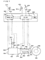
- the vehicle is equipped with an engine 1000, an automatic transmission 2000, a propeller shaft 5000, a differential gear 6000, rear wheels 7000, and an ECU (Electronic Control Unit) 8000.
- Automatic transmission 2000 includes a torque converter 2100, a transmission mechanism including a planetary gear unit 3000, and a hydraulic circuit 4000.
- the control device according to the present embodiment is realized by executing a program recorded in a ROM (Read Only Memory) 8002 of ECU 8000, for example.
- Engine 1000 is an internal combustion engine that bums mixed gas of fuel injected from an injector (not shown) and air in a combustion room of a cylinder. A piston in the cylinder is pressed down by the combustion, so that a crank shaft is rotated. An auxiliary machine 1004 such as an alternator or an air conditioner is driven by a driving force of engine 1000. It is to be noted that a motor may be used as a mechanical power source in place of or in addition to engine 1000.
- Torque converter 2100 has an input shaft coupled to an output shaft of engine 1000.
- Automatic transmission 2000 forms a desired shift stage to change a rotation speed of the crank shaft to a desired rotation speed.
- a driving force outputted from automatic transmission 2000 is transmitted to left and right rear wheels 7000, respectively, via propeller shaft 5000 and differential gear 6000.
- ECU 8000 is connected with a position switch 8006 of a shift lever 8004, an accelerator position sensor 8010 of an accelerator pedal 8008, a foot pressing force sensor 8014 of a brake pedal 8012, a throttle opening sensor 8018 of an electronic throttle valve 8016, an engine rotation speed sensor 8020, a turbine rotation speed sensor 8022, an output shaft rotation speed sensor 8024, an oil temperature sensor 8026, and a water temperature sensor 8028, through a harness and the like.
- a position of shift lever 8004 is detected by position switch 8006, and a signal indicating a result of the detection is sent to ECU 8000.
- the shift stage of automatic transmission 2000 is formed automatically.
- a configuration may be such that a manual shift mode in which a driver can select an optional shift stage can be selected in accordance with an operation by the driver.
- Accelerator position sensor 8010 detects a degree of pressing down the accelerator pedal 8008, and sends a signal indicating a result of the detection to ECU 8000.
- Foot pressing force sensor 8014 detects a foot pressing force of brake pedal 8012 (a force generated when the driver steps on brake pedal 8012), and sends a signal indicating a result of the detection to ECU 8000.
- Throttle opening sensor 8018 detects an opening degree of electronic throttle valve 8016 of which the opening degree is regulated by an actuator, and sends a signal indicating a result of the detection to ECU 8000.
- a volume of air to be drawn into engine 1000 is regulated by electronic throttle valve 8016.
- the volume of air to be drawn into engine 1000 may be regulated by changing a lift amount of an intake valve (not shown) or an exhaust valve (not shown) or a phase to be opened/closed, in place of or in addition to electronic throttle valve 8016.
- Engine rotation speed sensor 8020 detects a rotation speed of the output shaft (the crank shaft) of engine 1000, and sends a signal indicating a result of the detection to ECU 8000.
- Turbine rotation speed sensor 8022 detects a turbine rotation speed NT of torque converter 2100, and sends a signal indicating a result of the detection to ECU 8000.
- Output shaft rotation speed sensor 8024 detects an output shaft rotation speed NO of automatic transmission 2000, and sends a signal indicating a result of the detection to ECU 8000.
- Oil temperature sensor 8026 detects a temperature (an oil temperature) of oil (ATF: Automatic Transmission Fluid) used for actuation or lubrication of automatic transmission 2000, and sends a signal indicating a result of the detection to ECU 8000.
- ATF Automatic Transmission Fluid
- Water temperature sensor 8028 detects a temperature (a water temperature) of cooling water for engine 1000, and sends a signal indicating a result of the detection to ECU 8000.
- ECU 8000 controls devices such that the vehicle is in a desired running state.
- ECU 8000 controls automatic transmission 2000 such that one of forward first to eighth shift stages is formed in a case where a D (drive) range is selected as a shift range of automatic transmission 2000 because shift lever 8004 is in a D (drive) position.
- automatic transmission 2000 can transmit the driving force to rear wheels 7000.
- a configuration may be such that a shift stage higher than the eighth shift stage can be formed in the D range.
- a shift stage to be formed is determined based on a shift diagram which is prepared in advance by an experiment and the like with a vehicle speed and a degree of pressing down the accelerator being defined as parameters.
- ECU 8000 includes an engine ECU 8100 that controls engine 1000, and an ECT (Electronic Controlled Transmission) _ECU 8200 that controls automatic transmission 2000.
- ECT Electronic Controlled Transmission
- Engine ECU 8100 and ECT_ECU 8200 are configured such that a signal can be exchanged therebetween.
- a signal indicating a degree of pressing down the accelerator is sent from engine ECU 8100 to ECT_ECU 8200.
- a signal indicating a torque required amount determined as a torque to be outputted from engine 1000 is sent from ECT_ECU 8200 to engine ECU 8100.
- Planetary gear unit 3000 is connected to torque converter 2100 having input shaft 2102 coupled to the crank shaft.
- Planetary gear unit 3000 includes a front planetary 3100, a rear planetary 3200, a C1 clutch 3301, a C2 clutch 3302, a C3 clutch 3303, a C4 clutch 3304, a B1 brake 3311, a B2 brake 3312, and one-way clutch (F) 3320.
- Front planetary 3100 is a planetary gear mechanism of a double pinion type.
- Front planetary 3100 includes a first sun gear (S1) 3102, a pair of first pinion gears (P1) 3104, a carrier (CA) 3106, and a ring gear (R) 3108.
- First pinion gears (P1) 3104 are meshed with first sun gear (S1) 3102 and first ring gear (R) 3108, respectively.
- First carrier (CA) 3106 supports first pinion gear (P1) 3104 so as to allow revolution and rotation of first pinion gear (P1) 3104.
- First sun gear (S 1) 3102 is secured to a gear case 3400 such that first sun gear (S1) 3102 can not rotate.
- First carrier (CA) 3106 is coupled to an input shaft 3002 of planetary gear unit 3000.
- Rear planetary 3200 is a planetary gear mechanism of a Ravigneaux type.
- Rear planetary 3200 includes a second sun gear (S2) 3202, a second pinion gear (P2) 3204, a rear carrier (RCA) 3206, a rear ring gear (RR) 3208, a third sun gear (S3) 3210, and a third pinion gear (P3) 3212.
- Second pinion gear (P2) 3204 is meshed with second sun gear (S2) 3202, rear ring gear (RR) 3208 and third pinion gear (P3) 3212.
- Third pinion gear (P3) 3212 is meshed with third sun gear (S3) 3210 in addition to second pinion gear (P2) 3204.
- Rear carrier (RCA) 3206 supports second pinion gear (P2) 3204 and third pinion gear (P3) 3212 so as to allow revolution and rotation of second pinion gear (P2) 3204 and third pinion gear (P3) 3212.
- Rear carrier (RCA) 3206 is coupled to one-way clutch (F) 3320.
- Rear carrier (RCA) 3206 can not rotate when the vehicle is driven at the first shift stage (when the vehicle is running through use of the driving force outputted from engine 1000).
- Rear ring gear (RR) 3208 is coupled to an output shaft 3004 of planetary gear unit 3000.
- One-way clutch (F) 3320 is provided in parallel with B2 brake 3312. That is, one-way clutch (F) 3320 has an outer race secured to gear case 3400 and an inner race coupled to rear carrier (RCA) 3206.
- Fig. 3 shows an operation table that represents a relation between the respective shift stages and operating states of the respective clutches and the respective brakes.
- the shift stages including the forward first to eighth shift stages and rearward first and second shift stages are formed.
- hydraulic circuit 4000 is not limited to that to be described below.
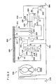
- Hydraulic circuit 4000 includes an oil pump 4004, a primary regulator valve 4006, a manual valve 4100, a solenoid modulator valve 4200, an SL1 linear solenoid (hereinafter, described as SL(1)) 4210, an SL2 linear solenoid (hereinafter, described as SL(2)) 4220, an SL3 linear solenoid (hereinafter, described as SL(3)) 4230, an SL4 linear solenoid (hereinafter, described as SL(4)) 4240, an SL5 linear solenoid (hereinafter, described as SL(5)) 4250, an SLT linear solenoid (hereinafter, described as SLT) 4300, and a B2 control valve 4500.
- SL(1) linear solenoid
- SL(2) linear solenoid
- SL(3) linear solenoid
- SL(4) linear solenoid
- SLT SLT linear solenoid
- Oil pump 4004 is coupled to the crank shaft of engine 1000. When the crank shaft is rotated, oil pump 4004 is driven to generate a hydraulic pressure. The hydraulic pressure generated by oil pump 4004 is regulated by primary regulator valve 4006, so that a line pressure is generated.
- Primary regulator valve 4006 is operated through use of, as a pilot pressure, a throttle pressure regulated by SLT 4300.
- the line pressure is supplied to manual valve 4100 through a line pressure oil path 4010.
- Manual valve 4100 includes a drain port 4105.
- a hydraulic pressure on a D range pressure oil path 4102 and a hydraulic pressure on an R range pressure oil path 4104 are discharged from drain port 4105.
- line pressure oil path 4010 and D range pressure oil path 4102 are communicatively connected with each other, so that the hydraulic pressure is supplied to D range pressure oil path 4102.
- R range pressure oil path 4104 and drain port 4105 are communicatively connected with each other, so that the R range pressure on R range pressure oil path 4104 is discharged from drain port 4105.
- line pressure oil path 4010 and R range pressure oil path 4104 are communicatively connected with each other, so that the hydraulic pressure is supplied to R range pressure oil path 4104.
- D range pressure oil path 4102 and drain port 4105 are communicatively connected with each other, so that the D range pressure on D range pressure oil path 4102 is discharged from drain port 4105.
- both D range pressure oil path 4102 and R range pressure oil path 4104 and drain port 4105 are communicatively connected with each other, so that the D range pressure on D range pressure oil path 4102 and the R range pressure on R range pressure oil path 4104 are discharged from drain port 4105.
- the hydraulic pressure supplied to D range pressure oil path 4102 is finally supplied to C1 clutch 3301, C2 clutch 3302 and C3 clutch 3303.
- the hydraulic pressure supplied to R range pressure oil path 4104 is finally supplied to B2 brake 3312.
- solenoid modulator valve 4200 regulates a hydraulic pressure (a solenoid modulator pressure) to be supplied to SLT 4300 to a certain pressure.
- SL(1) 4210 regulates the hydraulic pressure to be supplied to C1 clutch 3301.
- SL(2) 4220 regulates the hydraulic pressure to be supplied to C2 clutch 3302.
- SL(3) 4230 regulates the hydraulic pressure to be supplied to C3 clutch 3303.
- SL(4) 4240 regulates the hydraulic pressure to be supplied to C4 clutch 3304.
- SL(5) 4250 regulates the hydraulic pressure to be supplied to B 1 brake 3311.
- SLT 4300 regulates the solenoid modulator pressure and generates the throttle pressure in accordance with a control signal from ECU 8000 based on a degree of pressing down the accelerator detected by accelerator position sensor 8010.
- the throttle pressure is supplied to primary regulator valve 4006 through an SLT oil path 4302.
- the throttle pressure is used as the pilot pressure for primary regulator valve 4006.
- SL(1) 4210, SL(2) 4220, SL(3) 4230, SL(4) 4240, SL(5) 4250 and SLT 4300 are controlled by control signals sent from ECU 8000.
- B2 control valve 4500 selectively supplies the hydraulic pressure from any one of D range pressure oil path 4102 and R range pressure oil path 4104 to B2 brake 3312. D range pressure oil path 4102 and R range pressure oil path 4104 are connected to B2 control valve 4500.
- B2 control valve 4500 is controlled by a hydraulic pressure supplied from an SLU solenoid valve (not shown) and a bias force of a spring.
- B2 control valve 4500 is in a state shown at a left side in Fig. 4 .
- a hydraulic pressure obtained by regulating the D range pressure is supplied to B2 brake 3312 through use of, as the pilot pressure, the hydraulic pressure supplied from the SLU solenoid valve.
- B2 control valve 4500 is in a state shown at a right side in Fig. 4 .
- the R range pressure is supplied to B2 brake 3312.
- ECU 8000 determines whether or not a condition indicating delay of a shift is established, based on a state of automatic transmission 2000, after formation of a shift stage after a down shift began by increase of a degree of pressing down the accelerator.
- ECU 8000 outputs a command value corresponding to a hydraulic pressure to be supplied to a frictional engagement element on an engagement side such that the command value increases at a rate of change (1) which is determined in advance with a predetermined value being defined as an initial value.
- ECU 8000 If the degree of pressing down the accelerator increases while ECU 8000 outputs the command value such that the command value increases at the predetermined rate of change (1), ECU 8000 outputs a command value such that the command value increases at a rate of change (2) which is determined in advance and is different from the predetermined rate of change (1).
- the present invention has a feature in that ECU 8000 is operated as described above.
- ECU 8000 performs a power-on down shift when a position on a shift diagram, which is specified by a degree of pressing down the accelerator and a vehicle speed, traverses a down shift line by increase of the degree of pressing down the accelerator.
- ECU 8000 determines whether or not the vehicle is in a driven state. ECU 8000 determines whether or not the vehicle is in the driven state, based on at least any one of the vehicle speed and the degree of pressing down the accelerator.
- ECU 8000 determines whether or not a shift stage after the down shift is formed until a predetermined time elapses from the time point at which ECU 8000 determines that the vehicle is in the driven state. ECU 8000 determines that the shift stage after the down shift is not formed if a difference between turbine rotation speed NT and a synchronized rotation speed corresponding to the shift stage after the down shift does not narrow.
- ECU 8000 outputs a command value such that the command value increases at a rate of change (1) which is determined in advance with a predetermined value being defined as an initial value. Then, if the degree of pressing down the accelerator increases beyond a predetermined degree while ECU 8000 outputs the command value such that the command value increases at the predetermined rate of change (1), ECU 8000 outputs a command value such that the command value increases at a rate of change (2) which is determined in advance and is higher than the predetermined rate of change.
- Fig. 5 shows a functional block diagram of ECU 8000 which is the control device for the vehicle according to the present embodiment.
- ECU 8000 includes an input interface (hereinafter, described as input I/F) 300, a processing unit 400, a storage unit 500, and an output interface (hereinafter, described as output I/F) 600.
- input I/F input interface
- processing unit 400 processing unit 400
- storage unit 500 storage unit 500
- output I/F output interface
- Input I/F 300 receives an engine rotation speed signal from engine rotation speed sensor 8020, an accelerator position signal from accelerator position sensor 8010, a turbine rotation speed signal from turbine rotation speed sensor 8022 and an output shaft rotation speed signal from output shaft rotation speed sensor 8024, and then sends these signals to processing unit 400.
- Processing unit 400 includes a power-on down shift processing unit 402, a shift stage determining unit 404, a sweep control unit (1) 406, an accelerator position determining unit 408, and a sweep control unit (2) 410.
- Power-on down shift processing unit 402 executes a power-on down shift process based on a state of automatic transmission 2000. Specifically, when a position on a shift diagram based on a degree of pressing down the accelerator and a vehicle speed traverses a down shift line provided on the shift diagram in a case where the degree of pressing down the accelerator increases, power-on down shift processing unit 402 outputs a shift stage corresponding to the down shift line as a shift stage after a shift, and executes the power-on down shift process such that the vehicle runs at the shift stage after the shift.
- Power-on down shift processing unit 402 specifies the position on the shift diagram based on the degree of pressing down the accelerator and the vehicle speed, based on an accelerator position signal and an output shaft rotation speed signal. For example, the vehicle speed may be calculated from a product of an output shaft rotation speed and a speed reducing ratio from automatic transmission 2000 to the wheel or may be calculated based on a wheel speed detected by a wheel speed sensor (not shown).
- Power-on down shift processing unit 402 executes disengagement control that lowers a hydraulic pressure to be supplied to a frictional engagement element on a disengagement side and, further, executes engagement control that raises a hydraulic pressure to be supplied to a frictional engagement element on an engagement side such that a frictional engagement element corresponding to the shift stage after the shift is in an engaged state.
- shift stage determining unit 404 determines whether or not a condition indicating delay of a shift is established until a predetermined time elapses from the time point at which the vehicle is in the driven state.
- the condition indicating the delay of the shift refers to a condition that turbine rotation speed NT does not increase to a synchronized rotation speed corresponding to a shift stage after a down shift until the predetermined time elapses from the time point at which the vehicle is in the driven state.
- Shift stage determining unit 404 determines whether or not the vehicle is in the driven state, based on a fact the accelerator is deactivated in a state that the degree of pressing down the accelerator is lower than a predetermined degree A(0) after commencement of the power-on down shift. It is to be noted that shift stage determining unit 404 may determine whether or not the vehicle is in the driven state, based on the vehicle speed in addition to or in place of the degree of pressing down the accelerator. For example, shift stage determining unit 404 may determine that the vehicle is in the driven state when the vehicle speed shows a change corresponding to a decelerated state of the vehicle.
- shift stage determining unit 404 determines that turbine rotation speed NT does not increase to the synchronized rotation speed corresponding to the shift stage after the down shift, that is, determines that the condition indicating the delay of the shift is established.
- sweep control unit (1) 406 When shift stage determining unit 404 determines that turbine rotation speed NT does not increase to the synchronized rotation speed corresponding to the shift stage after the down shift, sweep control unit (1) 406 outputs a command value via output I/F 600 such that the command value increases at a rate of change (1) which is determined in advance with the command value outputted currently being defined as an initial value.
- sweep control (1) the control for increasing the command value for the hydraulic pressure at the predetermined rate of change (1). It is to be noted that, for example, sweep control unit (1) 406 may execute the sweep control (1) while setting a sweep control (1) execution flag.
- sweep control unit (1) 406 may output a command value such that the command value increases at a rate of change (1) which is determined in advance with a predetermined value being defined as an initial value.
- accelerator position determining unit 408 determines whether or not a degree of pressing down the accelerator received from input I/F 300 is predetermined opening A(0) or more. It is to be noted that, for example, accelerator position determining unit 408 may determine whether or not the degree of pressing down the accelerator is predetermined degree A(0) or more when the sweep control (1) execution flag is set. Moreover, accelerator position determining unit 408 may set an accelerator position determination flag when the degree of pressing down the accelerator is predetermined degree A(0) or more, for example.
- sweep control unit (2) 410 When accelerator position determining unit 408 determines that the degree of pressing down the accelerator is predetermined degree A(0) or more, sweep control unit (2) 410 outputs a command value via output I/F 600 such that the command value increases at a rate of change (2) which is determined in advance with the current command value being defined as an initial value.
- sweep control (2) the control for increasing the command value for the hydraulic pressure at the predetermined rate of change (2). It is to be noted that, for example, sweep control unit (2) 410 may execute the sweep control (2) when the accelerator position determination flag is set.
- the predetermined rate of change (2) is not particularly limited as long as it is higher than at least “the predetermined rate of change (1)” and has such a value that a rate of change of a hydraulic pressure to be supplied to a frictional engagement element on an engagement side becomes high, for example, a value adapted by an experiment and the like.
- sweep control unit (2) 406 may output a command value such that the command value increases at a rate of change (2) which is determined in advance with a predetermined value being defined as an initial value.
- each of power-on down shift processing unit 402, shift stage determining unit 404, sweep control unit (1) 406, accelerator position determining unit 408 and sweep control unit (2) 410 is described as a part which functions as software realized in such a manner that a CPU corresponding to processing unit 400 executes a program stored in storage unit 500; however, such a part may be realized by hardware. It is to be noted that this program is installed on the vehicle while being recorded in a recording medium.
- Storage unit 500 stores various kinds of information, programs, threshold values, maps and the like, and processing unit 400 reads/stores data from/in storage unit 500 if necessary.
- ECU 8000 is the control device for the vehicle according to the present embodiment.
- step (hereinafter, the term, step, will be described as S) 100, when the position on the shift diagram based on the degree of pressing down the accelerator and the vehicle speed traverses the down shift line by the increase of the degree of pressing down the accelerator, ECU 8000 outputs the shift stage corresponding to the down shift line, and executes the power-on down shift.
- ECU 8000 determines whether or not turbine rotation speed NT increases to the synchronized rotation speed corresponding to the shift stage after the down shift after the accelerator is deactivated. If turbine rotation speed NT increases to the synchronized rotation speed corresponding to the shift stage after the down shift (YES in S102), this process is completed. If not (NO in S102), this process proceeds to S 104.
- ECU 8000 executes the sweep control (1).
- ECU 8000 determines whether or not the shift stage after the shift is formed. For example, when the absolute value of the difference between turbine rotation speed NT and the synchronized rotation speed corresponding to the shift stage after the shift is the predetermined value or less, ECU 8000 determines that the shift stage after the shift is formed. If the shift stage after the shift is formed (YES in S 106), this process is completed. If not (NO in S106), this process proceeds to S108.
- ECU 8000 determines whether or not the accelerator is activated. That is, when the degree of pressing down the accelerator is the predetermined degree or more, ECU 8000 determines that the accelerator is activated. If the accelerator is activated (YES in S 108), this process proceeds to S110. If not (NO in S 108); this process returns to S 104. In S110, ECU 8000 executes the sweep control (2).
- ECU 8000 is the control device for the vehicle according to the present embodiment, based on the structure and the flow chart each described above.
- a shift output is the fifth shift stage.
- T(0) when the driver steps on the accelerator pedal to increase the degree of pressing down the accelerator, the position on the shift diagram based on the degree of pressing down the accelerator and the vehicle speed traverses a down shift line from the fifth shift stage to a fourth shift stage, a down shift line from the fourth shift stage to a third shift stage, and a down shift line from the third shift stage to a second shift stage, so that the shift output becomes the second shift stage (S100). Therefore, a power-on down shift from the fifth shift stage which is the current shift stage to the second shift stage begins.
- an engaging pressure for C2 clutch 3302 lowers while an engaging pressure for B 1 brake 3311 increases, so that turbine rotation speed NT starts to increase.
- the driver operates the accelerator pedal at the disengagement side.
- a time T(4) when the degree of pressing down the accelerator is lower than predetermined degree A(0), it is determined that the accelerator is deactivated.
- the rotation speed of engine 1000 decreases.
- turbine rotation speed NT starts to decrease conversely.
- control command pressure increases at a rate of change (1) which is determined in advance with current command pressure P(2) being defined as an initial value.
- control command pressure increases at a rate of change (2) which is determined in advance with current command pressure P(3) being defined as an initial value.
- a degree of raise of the engaging pressure for B1 brake 3311 becomes larger in the case where the command value increases at the predetermined rate of change (2) in comparison with the case where the command value increases at the predetermined rate of change (1). Therefore, turbine rotation speed NT promptly approaches the synchronized rotation speed corresponding to the second shift stage.
- the condition indicating the delay of the shift e.g., the condition that the turbine rotation speed does not increase to the synchronized rotation speed after the shift after the accelerator is deactivated
- the command value corresponding to the hydraulic pressure to be supplied to the frictional engagement element on the engagement side is outputted such that the command value increases at the rate of change (1) which is determined in advance with the predetermined value being defined as the initial value.
- the command value is outputted such that the command value increases at the predetermined rate of change (2).
- the predetermined rate of change (2) is a value that increases the hydraulic value largely in comparison with the predetermined rate of change (1); therefore, the engaging pressure for the frictional engagement element on the engagement side increases promptly.
- the engaging pressure for the frictional engagement element on the engagement side can prevent the turbine rotation speed of the automatic transmission from increasing more than necessary. Accordingly, it is possible to provide a control device and a control method for a vehicle that appropriately engages a frictional engagement element on an engagement side in accordance with an operation of an accelerator to smoothly progress a shift after commencement of a power-on down shift.
- the determination whether or not the shift stage after the down shift is formed until the predetermined time elapses from the time point at which it is determined that the vehicle is in the driven state, based on at least any one of the vehicle speed and the degree of pressing down the accelerator allows the determination whether or not the shift is delayed.
Landscapes
- Engineering & Computer Science (AREA)
- General Engineering & Computer Science (AREA)
- Physics & Mathematics (AREA)
- Fluid Mechanics (AREA)
- Mechanical Engineering (AREA)
- Control Of Transmission Device (AREA)
- Control Of Fluid Gearings (AREA)
Claims (12)
- Steuervorrichtung für ein Fahrzeug, das mit einem Automatikgetriebe (2000) ausgestattet ist, das eine Schaltstufe nach einem Herunterschalten derart bildet, dass mittels eines Hydraulikdrucks, der basierend auf einem an einen Hydraulikkreislauf (4000) ausgegebenen Befehlswert angelegt ist, ein nicht in Eingriff befindliches erstes Reibeingriffselement in Eingriff gebracht wird, während ein in Eingriff befindliches zweites Reibeingriffselement außer Eingriff gebracht wird,
wobei die Steuervorrichtung umfasst:eine Erfassungseinheit (8010, 8022), die eine einen Zustand des Automatikgetriebes (2000) betreffende physikalische Größe erfasst; undeine Steuereinheit (8000), die mit der Erfassungseinheit (8010, 8022) verbunden ist, wobeidie Steuereinheit (8000) bestimmt, ob eine auf eine Schaltverzögerung hinweisende Bedingung basierend auf einem Zustand des Automatikgetriebes (2000) besteht oder nicht, nachdem eine Erhöhung eines Betätigungsausmaßes eines Fahrpedals einen Beginn einer Bildung der Schaltstufe nach dem Herunterschalten auslöst, wobei,wenn die Bedingung besteht, die Steuereinheit (8000) einen Befehlswert entsprechend dem an das erste Reibeingriffselement anzulegenden Hydraulikdruck derart ausgibt, dass sich der Befehlswert mit einer ersten Änderungsrate erhöht, die vorab mit einem als ein Initialwert definierten vorbestimmten Wert bestimmt ist, undwenn sich das Betätigungsausmaß des Fahrpedals erhöht, während die Steuereinheit (8000) den Befehlswert derart ausgibt, dass sich der Befehlswert mit der ersten Änderungsrate erhöht, die Steuereinheit (8000) einen Befehlswert derart ausgibt, dass sich der Befehlswert mit einer zweiten Änderungsrate erhöht, die vorab bestimmt ist und sich von der ersten Änderungsrate unterscheidet. - Steuervorrichtung für das Fahrzeug gemäß Anspruch 1, wobei die zweite Änderungsrate höher als die erste Änderungsrate ist.
- Steuervorrichtung für das Fahrzeug gemäß Anspruch 1, ferner mit
einer Ausmaßerfassungseinheit (8010), die das Betätigungsausmaß des Fahrpedals erfasst, wobei
wenn das erfasste Betätigungsausmaß des Fahrpedals ein vorbestimmtes Ausmaß erreicht oder größer wird, während die Steuereinheit (8000) den Befehlswert derart ausgibt, dass sich der Befehlswert mit der ersten Änderungsrate erhöht, die Steuereinheit (8000) den Befehlswert derart ausgibt, dass sich der Befehlswert mit der zweiten Änderungsrate erhöht. - Steuervorrichtung für das Fahrzeug gemäß einem der Ansprüche 1 bis 3, wobei
die Steuereinheit (8000) bestimmt, ob das Fahrzeug in einem fahrenden Zustand ist oder nicht, und
die Steuereinheit (8000) bestimmt, ob die Schaltstufe nach dem Herunterschalten bis zu einem Verstreichen einer vorbestimmten Zeit von einem Zeitpunkt gebildet ist oder nicht, zu dem die Steuereinheit (8000) bestimmt, dass das Fahrzeug in dem fahrenden Zustand ist. - Steuervorrichtung für das Fahrzeug gemäß Anspruch 4, wobei
die Steuereinheit (8000) basierend auf zumindest irgendeinem aus einer Fahrzeuggeschwindigkeit und dem Betätigungsausmaß des Fahrpedals bestimmt, ob das Fahrzeug in dem fahrenden Zustand ist oder nicht. - Steuervorrichtung für das Fahrzeug gemäß Anspruch 4, wobei
das Automatikgetriebe (2000) eine mit einer Abtriebswelle einer Brennkraftmaschine (1000) gekoppelte Flüssigkeitskopplung (3200) und einen mit der Flüssigkeitskopplung (3200) gekoppelten Übertragungsmechanismus (3000) aufweist,
wobei die Steuervorrichtung ferner eine Rotationsgeschwindigkeitserfassungseinheit (8022) umfasst, die eine Rotationsgeschwindigkeit einer Eingangswelle des Übertragungsmechanismus (3000) erfasst, wobei
die Steuereinheit (8000) bestimmt, dass die Schaltstufe nach dem Herunterschalten nicht gebildet ist, solange sich ein Absolutwert einer Differenz zwischen der erfassten Eingangswellenrotationsgeschwindigkeit und einer der Schaltstufe nach dem Herunterschalten entsprechenden Rotationsgeschwindigkeit nicht auf einen vorbestimmten Wert oder auf einen kleineren verringert. - Steuerverfahren für ein Fahrzeug, das mit einem Automatikgetriebe ausgestattet ist, das eine Schaltstufe nach einem Herunterschalten derart bildet, dass mittels eines Hydraulikdrucks, der basierend auf einem an einen Hydraulikkreislauf (4000) ausgegebenen Befehlswert angelegt ist, ein nicht in Eingriff befindliches erstes Reibeingriffselement in Eingriff gebracht wird, während ein in Eingriff befindliches zweites Reibeingriffselement außer Eingriff gebracht wird,
wobei das Steuerverfahren umfasst:einen Erfassungsschritt, in dem eine einen Zustand des Automatikgetriebes (2000) betreffende physikalische Größe erfasst wird;einen Bestimmungsschritt, in dem bestimmt wird, ob eine auf eine Schaltverzögerung hinweisende Bedingung basierend auf einem Zustand des Automatikgetriebes (2000) besteht oder nicht, nachdem eine Erhöhung eines Betätigungsausmaßes eines Fahrpedals einen Beginn einer Bildung der Schaltstufe nach dem Herunterschalten auslöst,einen Schritt, in dem, wenn die Bedingung besteht, ein Befehlswert entsprechend dem an das erste Reibeingriffselement anzulegenden Hydraulikdruck derart ausgegeben wird, dass sich der Befehlswert mit einer ersten Änderungsrate erhöht, die vorab mit einem als ein Initialwert definierten vorbestimmten Wert bestimmt wird, undeinen Ausgabeschritt, in dem, wenn sich das Betätigungsausmaß des Fahrpedals erhöht, während der Befehlswert derart ausgegeben wird, dass sich der Befehlswert mit der ersten Änderungsrate erhöht, ein Befehlswert derart ausgegeben wird, dass sich der Befehlswert mit einer zweiten Änderungsrate erhöht, die vorab bestimmt wird und sich von der ersten Änderungsrate unterscheidet. - Steuerverfahren für das Fahrzeug gemäß Anspruch 7, wobei die zweite Änderungsrate höher als die erste Änderungsrate ist.
- Steuerverfahren für das Fahrzeug gemäß Anspruch 7, ferner mit
einem Schritt, in dem das Betätigungsausmaß des Fahrpedals erfasst wird, wobei
der Ausgabeschritt einen Schritt aufweist, in dem, wenn das erfasste Betätigungsausmaß des Fahrpedals ein vorbestimmtes Ausmaß erreicht oder größer wird, während der Befehlswert derart ausgegeben wird, dass sich der Befehlswert mit der ersten Änderungsrate erhöht, der Befehlswert derart ausgegeben wird, dass sich der Befehlswert mit der zweiten Änderungsrate erhöht. - Steuerverfahren für das Fahrzeug gemäß einem der Ansprüche 7 bis 9, wobei
der Bestimmungsschritt aufweist:einen Zustandsbestimmungsschritt, in dem bestimmt wird, ob das Fahrzeug in einem fahrenden Zustand ist oder nicht, undeinen Schaltstufenbestimmungsschritt, in dem bestimmt wird, ob die Schaltstufe nach dem Herunterschalten bis zu einem Verstreichen einer vorbestimmten Zeit von einem Zeitpunkt gebildet ist oder nicht, zu dem bestimmt ist, dass das Fahrzeug in dem fahrenden Zustand ist. - Steuerverfahren für das Fahrzeug gemäß Anspruch 10, wobei
der Zustandsbestimmungsschritt einen Schritt aufweist, in dem basierend auf zumindest irgendeinem aus einer Fahrzeuggeschwindigkeit und dem Betätigungsausmaß des Fahrpedals bestimmt wird, ob das Fahrzeug in dem fahrenden Zustand ist oder nicht. - Steuerverfahren für das Fahrzeug gemäß Anspruch 10, wobei
das Automatikgetriebe (2000) eine mit einer Abtriebswelle einer Brennkraftmaschine (1000) gekoppelte Flüssigkeitskopplung (3200) und einen mit der Flüssigkeitskopplung (3200) gekoppelten Übertragungsmechanismus (3000) aufweist,
wobei das Steuerverfahren ferner einen Schritt umfasst, in dem eine Rotationsgeschwindigkeit einer Eingangswelle des Übertragungsmechanismus (3000) erfasst wird, wobei
der Schaltstufenbestimmungsschritt einen Schritt aufweist, in dem bestimmt wird, dass die Schaltstufe nach dem Herunterschalten nicht gebildet ist, solange sich ein Absolutwert einer Differenz zwischen der erfassten Eingangswellenrotationsgeschwindigkeit und einer der Schaltstufe nach dem Herunterschalten entsprechenden Rotationsgeschwindigkeit nicht auf einen vorbestimmten Wert oder auf einen kleineren verringert.
Applications Claiming Priority (2)
| Application Number | Priority Date | Filing Date | Title |
|---|---|---|---|
| JP2007205730A JP5217294B2 (ja) | 2007-08-07 | 2007-08-07 | 車両の制御装置、制御方法およびその方法をコンピュータに実現させるプログラムならびにそのプログラムを記録した記録媒体 |
| PCT/JP2008/063926 WO2009020083A2 (en) | 2007-08-07 | 2008-07-28 | Control device and control method for vehicle |
Publications (2)
| Publication Number | Publication Date |
|---|---|
| EP2176571A2 EP2176571A2 (de) | 2010-04-21 |
| EP2176571B1 true EP2176571B1 (de) | 2013-08-21 |
Family
ID=40336490
Family Applications (1)
| Application Number | Title | Priority Date | Filing Date |
|---|---|---|---|
| EP08792133.4A Not-in-force EP2176571B1 (de) | 2007-08-07 | 2008-07-28 | Steuervorrichtung und steuerverfahren für ein fahrzeug |
Country Status (5)
| Country | Link |
|---|---|
| US (1) | US8589041B2 (de) |
| EP (1) | EP2176571B1 (de) |
| JP (1) | JP5217294B2 (de) |
| CN (1) | CN101772660B (de) |
| WO (1) | WO2009020083A2 (de) |
Families Citing this family (10)
| Publication number | Priority date | Publication date | Assignee | Title |
|---|---|---|---|---|
| JP5912327B2 (ja) * | 2011-08-03 | 2016-04-27 | アイシン・エーアイ株式会社 | デュアルクラッチ式自動変速機 |
| US8510005B1 (en) * | 2012-07-19 | 2013-08-13 | GM Global Technology Operations LLC | PID-based torque phase control of a power downshift |
| CN104662336B (zh) * | 2012-09-27 | 2016-09-07 | 加特可株式会社 | 无级变速器及其控制方法 |
| JP5939134B2 (ja) * | 2012-11-09 | 2016-06-22 | トヨタ自動車株式会社 | 車両状態記憶装置 |
| JP5840262B1 (ja) * | 2014-07-03 | 2016-01-06 | 三菱電機株式会社 | 船舶のアイドル回転数制御装置および船舶のアイドル回転数制御方法 |
| JP6461054B2 (ja) * | 2016-07-28 | 2019-01-30 | トヨタ自動車株式会社 | 車両の制御装置 |
| JP6449820B2 (ja) * | 2016-07-29 | 2019-01-09 | トヨタ自動車株式会社 | 車両の制御装置 |
| JP6565884B2 (ja) | 2016-12-05 | 2019-08-28 | トヨタ自動車株式会社 | 車両の変速制御装置 |
| JP6673261B2 (ja) * | 2017-02-24 | 2020-03-25 | トヨタ自動車株式会社 | 車両の変速制御装置 |
| JP7444109B2 (ja) * | 2021-03-03 | 2024-03-06 | トヨタ自動車株式会社 | 車両用制御装置 |
Family Cites Families (12)
| Publication number | Priority date | Publication date | Assignee | Title |
|---|---|---|---|---|
| JP2910384B2 (ja) * | 1992-03-16 | 1999-06-23 | 日産自動車株式会社 | 自動変速機の変速制御装置 |
| JP3427563B2 (ja) * | 1995-04-21 | 2003-07-22 | トヨタ自動車株式会社 | 自動変速機の制御装置 |
| JP3191666B2 (ja) | 1996-02-27 | 2001-07-23 | トヨタ自動車株式会社 | 自動変速機の制御装置 |
| JP4107795B2 (ja) * | 2000-09-18 | 2008-06-25 | ジヤトコ株式会社 | 自動変速機の油圧制御装置 |
| JP4070549B2 (ja) | 2002-09-06 | 2008-04-02 | 本田技研工業株式会社 | 自動変速機の制御装置 |
| JP4201561B2 (ja) * | 2002-10-03 | 2008-12-24 | ダイハツ工業株式会社 | 自動変速機の変速制御方法 |
| JP4201563B2 (ja) * | 2002-10-04 | 2008-12-24 | ダイハツ工業株式会社 | 自動変速機の変速制御方法 |
| JP4081384B2 (ja) * | 2003-02-10 | 2008-04-23 | ジヤトコ株式会社 | 自動車用自動変速機の変速制御装置 |
| JP4543734B2 (ja) * | 2004-04-26 | 2010-09-15 | トヨタ自動車株式会社 | 自動変速機の変速終了判定装置 |
| US7556586B2 (en) * | 2004-07-28 | 2009-07-07 | Komatsu Ltd. | Shift control device and shift control method for vehicle |
| JP4744192B2 (ja) * | 2005-05-23 | 2011-08-10 | 本田技研工業株式会社 | 自動変速機の制御装置 |
| JP2007162856A (ja) * | 2005-12-15 | 2007-06-28 | Toyota Motor Corp | 自動変速機の制御装置 |
-
2007
- 2007-08-07 JP JP2007205730A patent/JP5217294B2/ja not_active Expired - Fee Related
-
2008
- 2008-07-28 CN CN2008801022157A patent/CN101772660B/zh not_active Expired - Fee Related
- 2008-07-28 EP EP08792133.4A patent/EP2176571B1/de not_active Not-in-force
- 2008-07-28 US US12/670,593 patent/US8589041B2/en not_active Expired - Fee Related
- 2008-07-28 WO PCT/JP2008/063926 patent/WO2009020083A2/en not_active Ceased
Also Published As
| Publication number | Publication date |
|---|---|
| JP5217294B2 (ja) | 2013-06-19 |
| US8589041B2 (en) | 2013-11-19 |
| CN101772660B (zh) | 2012-12-26 |
| EP2176571A2 (de) | 2010-04-21 |
| WO2009020083A2 (en) | 2009-02-12 |
| CN101772660A (zh) | 2010-07-07 |
| WO2009020083A3 (en) | 2009-12-10 |
| US20100191430A1 (en) | 2010-07-29 |
| JP2009041626A (ja) | 2009-02-26 |
Similar Documents
| Publication | Publication Date | Title |
|---|---|---|
| EP2176571B1 (de) | Steuervorrichtung und steuerverfahren für ein fahrzeug | |
| US7544149B2 (en) | Shift control apparatus and shift control method of automatic transmission of vehicle | |
| EP2418401B1 (de) | Fahrzeug, fahrzeugsteuerungsverfahren und steuervorrichtung | |
| US7108633B2 (en) | Control apparatus for automatic transmission | |
| US9434373B2 (en) | Automatic transmission control device | |
| US20070255472A1 (en) | Powertrain control apparatus and method | |
| JP4400617B2 (ja) | パワートレーンの制御装置、制御方法、その方法を実現させるプログラムおよびそのプログラムを記録した記録媒体 | |
| US8498789B2 (en) | Control apparatus and control method for drive source | |
| US8226532B2 (en) | Control apparatus for automatic transmission, and control method for automatic transmission | |
| US20100250050A1 (en) | Control apparatus and control method for automatic transmission | |
| JP4967722B2 (ja) | 車両の制御装置および制御方法 | |
| JP5103833B2 (ja) | 車両の制御装置、制御方法、その制御方法をコンピュータに実行させるためのプログラムおよびプログラムを記録した記録媒体 | |
| JP2008064176A (ja) | 車両の制御装置 | |
| JP2009243492A (ja) | 自動変速機の制御装置 | |
| JPH06109130A (ja) | 自動変速機の油圧制御装置 | |
| JP5181565B2 (ja) | 車両の制御装置、制御方法およびその方法をコンピュータに実現されるプログラムならびにそのプログラムを記録した記録媒体 | |
| JP4929929B2 (ja) | 車両の制御装置、制御方法、その制御方法をコンピュータに実行させるためのプログラムおよびプログラムを記録した記録媒体 | |
| JP2005133895A (ja) | 自動変速制御装置 | |
| JP4983820B2 (ja) | パワートレーンの制御装置、制御方法、その方法を実現させるプログラムおよびそのプログラムを記録した記録媒体 | |
| JP2010203596A (ja) | 車両の制御装置 | |
| JP2008050948A (ja) | 車両の制御装置 | |
| JP2008208930A (ja) | 車両の制御装置、制御方法、その方法を実現するプログラムおよびそのプログラムを記録した記録媒体、車両の駆動装置。 | |
| JP2003049936A (ja) | 車両用自動変速機の学習制御方法及びシステム | |
| US20090099743A1 (en) | Control apparatus and control method for automatic transmission | |
| JP4983819B2 (ja) | パワートレーンの制御装置、制御方法、その方法を実現させるプログラムおよびそのプログラムを記録した記録媒体 |
Legal Events
| Date | Code | Title | Description |
|---|---|---|---|
| PUAI | Public reference made under article 153(3) epc to a published international application that has entered the european phase |
Free format text: ORIGINAL CODE: 0009012 |
|
| 17P | Request for examination filed |
Effective date: 20091229 |
|
| AK | Designated contracting states |
Kind code of ref document: A2 Designated state(s): AT BE BG CH CY CZ DE DK EE ES FI FR GB GR HR HU IE IS IT LI LT LU LV MC MT NL NO PL PT RO SE SI SK TR |
|
| DAX | Request for extension of the european patent (deleted) | ||
| RAP1 | Party data changed (applicant data changed or rights of an application transferred) |
Owner name: TOYOTA JIDOSHA KABUSHIKI KAISHA |
|
| GRAP | Despatch of communication of intention to grant a patent |
Free format text: ORIGINAL CODE: EPIDOSNIGR1 |
|
| RIC1 | Information provided on ipc code assigned before grant |
Ipc: F16H 59/20 20060101ALN20130208BHEP Ipc: F16H 61/06 20060101AFI20130208BHEP |
|
| GRAS | Grant fee paid |
Free format text: ORIGINAL CODE: EPIDOSNIGR3 |
|
| GRAA | (expected) grant |
Free format text: ORIGINAL CODE: 0009210 |
|
| AK | Designated contracting states |
Kind code of ref document: B1 Designated state(s): AT BE BG CH CY CZ DE DK EE ES FI FR GB GR HR HU IE IS IT LI LT LU LV MC MT NL NO PL PT RO SE SI SK TR |
|
| REG | Reference to a national code |
Ref country code: GB Ref legal event code: FG4D |
|
| REG | Reference to a national code |
Ref country code: CH Ref legal event code: EP |
|
| REG | Reference to a national code |
Ref country code: AT Ref legal event code: REF Ref document number: 628295 Country of ref document: AT Kind code of ref document: T Effective date: 20130915 |
|
| REG | Reference to a national code |
Ref country code: IE Ref legal event code: FG4D |
|
| REG | Reference to a national code |
Ref country code: DE Ref legal event code: R096 Ref document number: 602008027021 Country of ref document: DE Effective date: 20131017 |
|
| REG | Reference to a national code |
Ref country code: NL Ref legal event code: VDEP Effective date: 20130821 Ref country code: AT Ref legal event code: MK05 Ref document number: 628295 Country of ref document: AT Kind code of ref document: T Effective date: 20130821 |
|
| REG | Reference to a national code |
Ref country code: LT Ref legal event code: MG4D |
|
| PG25 | Lapsed in a contracting state [announced via postgrant information from national office to epo] |
Ref country code: SE Free format text: LAPSE BECAUSE OF FAILURE TO SUBMIT A TRANSLATION OF THE DESCRIPTION OR TO PAY THE FEE WITHIN THE PRESCRIBED TIME-LIMIT Effective date: 20130821 Ref country code: PT Free format text: LAPSE BECAUSE OF FAILURE TO SUBMIT A TRANSLATION OF THE DESCRIPTION OR TO PAY THE FEE WITHIN THE PRESCRIBED TIME-LIMIT Effective date: 20131223 Ref country code: HR Free format text: LAPSE BECAUSE OF FAILURE TO SUBMIT A TRANSLATION OF THE DESCRIPTION OR TO PAY THE FEE WITHIN THE PRESCRIBED TIME-LIMIT Effective date: 20130821 Ref country code: NO Free format text: LAPSE BECAUSE OF FAILURE TO SUBMIT A TRANSLATION OF THE DESCRIPTION OR TO PAY THE FEE WITHIN THE PRESCRIBED TIME-LIMIT Effective date: 20131121 Ref country code: IS Free format text: LAPSE BECAUSE OF FAILURE TO SUBMIT A TRANSLATION OF THE DESCRIPTION OR TO PAY THE FEE WITHIN THE PRESCRIBED TIME-LIMIT Effective date: 20131221 Ref country code: LT Free format text: LAPSE BECAUSE OF FAILURE TO SUBMIT A TRANSLATION OF THE DESCRIPTION OR TO PAY THE FEE WITHIN THE PRESCRIBED TIME-LIMIT Effective date: 20130821 Ref country code: AT Free format text: LAPSE BECAUSE OF FAILURE TO SUBMIT A TRANSLATION OF THE DESCRIPTION OR TO PAY THE FEE WITHIN THE PRESCRIBED TIME-LIMIT Effective date: 20130821 Ref country code: CY Free format text: LAPSE BECAUSE OF FAILURE TO SUBMIT A TRANSLATION OF THE DESCRIPTION OR TO PAY THE FEE WITHIN THE PRESCRIBED TIME-LIMIT Effective date: 20130821 |
|
| PG25 | Lapsed in a contracting state [announced via postgrant information from national office to epo] |
Ref country code: LV Free format text: LAPSE BECAUSE OF FAILURE TO SUBMIT A TRANSLATION OF THE DESCRIPTION OR TO PAY THE FEE WITHIN THE PRESCRIBED TIME-LIMIT Effective date: 20130821 Ref country code: FI Free format text: LAPSE BECAUSE OF FAILURE TO SUBMIT A TRANSLATION OF THE DESCRIPTION OR TO PAY THE FEE WITHIN THE PRESCRIBED TIME-LIMIT Effective date: 20130821 Ref country code: BE Free format text: LAPSE BECAUSE OF FAILURE TO SUBMIT A TRANSLATION OF THE DESCRIPTION OR TO PAY THE FEE WITHIN THE PRESCRIBED TIME-LIMIT Effective date: 20130821 Ref country code: GR Free format text: LAPSE BECAUSE OF FAILURE TO SUBMIT A TRANSLATION OF THE DESCRIPTION OR TO PAY THE FEE WITHIN THE PRESCRIBED TIME-LIMIT Effective date: 20131122 Ref country code: SI Free format text: LAPSE BECAUSE OF FAILURE TO SUBMIT A TRANSLATION OF THE DESCRIPTION OR TO PAY THE FEE WITHIN THE PRESCRIBED TIME-LIMIT Effective date: 20130821 Ref country code: PL Free format text: LAPSE BECAUSE OF FAILURE TO SUBMIT A TRANSLATION OF THE DESCRIPTION OR TO PAY THE FEE WITHIN THE PRESCRIBED TIME-LIMIT Effective date: 20130821 |
|
| REG | Reference to a national code |
Ref country code: DE Ref legal event code: R084 Ref document number: 602008027021 Country of ref document: DE Effective date: 20140304 |
|
| PG25 | Lapsed in a contracting state [announced via postgrant information from national office to epo] |
Ref country code: SK Free format text: LAPSE BECAUSE OF FAILURE TO SUBMIT A TRANSLATION OF THE DESCRIPTION OR TO PAY THE FEE WITHIN THE PRESCRIBED TIME-LIMIT Effective date: 20130821 Ref country code: RO Free format text: LAPSE BECAUSE OF FAILURE TO SUBMIT A TRANSLATION OF THE DESCRIPTION OR TO PAY THE FEE WITHIN THE PRESCRIBED TIME-LIMIT Effective date: 20130821 Ref country code: NL Free format text: LAPSE BECAUSE OF FAILURE TO SUBMIT A TRANSLATION OF THE DESCRIPTION OR TO PAY THE FEE WITHIN THE PRESCRIBED TIME-LIMIT Effective date: 20130821 Ref country code: DK Free format text: LAPSE BECAUSE OF FAILURE TO SUBMIT A TRANSLATION OF THE DESCRIPTION OR TO PAY THE FEE WITHIN THE PRESCRIBED TIME-LIMIT Effective date: 20130821 Ref country code: EE Free format text: LAPSE BECAUSE OF FAILURE TO SUBMIT A TRANSLATION OF THE DESCRIPTION OR TO PAY THE FEE WITHIN THE PRESCRIBED TIME-LIMIT Effective date: 20130821 Ref country code: CZ Free format text: LAPSE BECAUSE OF FAILURE TO SUBMIT A TRANSLATION OF THE DESCRIPTION OR TO PAY THE FEE WITHIN THE PRESCRIBED TIME-LIMIT Effective date: 20130821 |
|
| REG | Reference to a national code |
Ref country code: DE Ref legal event code: R097 Ref document number: 602008027021 Country of ref document: DE |
|
| PG25 | Lapsed in a contracting state [announced via postgrant information from national office to epo] |
Ref country code: ES Free format text: LAPSE BECAUSE OF FAILURE TO SUBMIT A TRANSLATION OF THE DESCRIPTION OR TO PAY THE FEE WITHIN THE PRESCRIBED TIME-LIMIT Effective date: 20130821 Ref country code: IT Free format text: LAPSE BECAUSE OF FAILURE TO SUBMIT A TRANSLATION OF THE DESCRIPTION OR TO PAY THE FEE WITHIN THE PRESCRIBED TIME-LIMIT Effective date: 20130821 |
|
| PLBE | No opposition filed within time limit |
Free format text: ORIGINAL CODE: 0009261 |
|
| STAA | Information on the status of an ep patent application or granted ep patent |
Free format text: STATUS: NO OPPOSITION FILED WITHIN TIME LIMIT |
|
| 26N | No opposition filed |
Effective date: 20140522 |
|
| REG | Reference to a national code |
Ref country code: DE Ref legal event code: R097 Ref document number: 602008027021 Country of ref document: DE Effective date: 20140522 |
|
| PG25 | Lapsed in a contracting state [announced via postgrant information from national office to epo] |
Ref country code: LU Free format text: LAPSE BECAUSE OF FAILURE TO SUBMIT A TRANSLATION OF THE DESCRIPTION OR TO PAY THE FEE WITHIN THE PRESCRIBED TIME-LIMIT Effective date: 20140728 |
|
| REG | Reference to a national code |
Ref country code: CH Ref legal event code: PL |
|
| GBPC | Gb: european patent ceased through non-payment of renewal fee |
Effective date: 20140728 |
|
| REG | Reference to a national code |
Ref country code: IE Ref legal event code: MM4A |
|
| PG25 | Lapsed in a contracting state [announced via postgrant information from national office to epo] |
Ref country code: LI Free format text: LAPSE BECAUSE OF NON-PAYMENT OF DUE FEES Effective date: 20140731 Ref country code: CH Free format text: LAPSE BECAUSE OF NON-PAYMENT OF DUE FEES Effective date: 20140731 |
|
| PG25 | Lapsed in a contracting state [announced via postgrant information from national office to epo] |
Ref country code: GB Free format text: LAPSE BECAUSE OF NON-PAYMENT OF DUE FEES Effective date: 20140728 |
|
| PG25 | Lapsed in a contracting state [announced via postgrant information from national office to epo] |
Ref country code: IE Free format text: LAPSE BECAUSE OF NON-PAYMENT OF DUE FEES Effective date: 20140728 |
|
| PG25 | Lapsed in a contracting state [announced via postgrant information from national office to epo] |
Ref country code: MC Free format text: LAPSE BECAUSE OF FAILURE TO SUBMIT A TRANSLATION OF THE DESCRIPTION OR TO PAY THE FEE WITHIN THE PRESCRIBED TIME-LIMIT Effective date: 20130821 |
|
| PG25 | Lapsed in a contracting state [announced via postgrant information from national office to epo] |
Ref country code: BG Free format text: LAPSE BECAUSE OF FAILURE TO SUBMIT A TRANSLATION OF THE DESCRIPTION OR TO PAY THE FEE WITHIN THE PRESCRIBED TIME-LIMIT Effective date: 20130821 |
|
| REG | Reference to a national code |
Ref country code: FR Ref legal event code: PLFP Year of fee payment: 9 |
|
| PG25 | Lapsed in a contracting state [announced via postgrant information from national office to epo] |
Ref country code: MT Free format text: LAPSE BECAUSE OF FAILURE TO SUBMIT A TRANSLATION OF THE DESCRIPTION OR TO PAY THE FEE WITHIN THE PRESCRIBED TIME-LIMIT Effective date: 20130821 |
|
| PG25 | Lapsed in a contracting state [announced via postgrant information from national office to epo] |
Ref country code: HU Free format text: LAPSE BECAUSE OF FAILURE TO SUBMIT A TRANSLATION OF THE DESCRIPTION OR TO PAY THE FEE WITHIN THE PRESCRIBED TIME-LIMIT; INVALID AB INITIO Effective date: 20080728 Ref country code: TR Free format text: LAPSE BECAUSE OF FAILURE TO SUBMIT A TRANSLATION OF THE DESCRIPTION OR TO PAY THE FEE WITHIN THE PRESCRIBED TIME-LIMIT Effective date: 20130821 |
|
| REG | Reference to a national code |
Ref country code: FR Ref legal event code: PLFP Year of fee payment: 10 |
|
| REG | Reference to a national code |
Ref country code: FR Ref legal event code: PLFP Year of fee payment: 11 |
|
| PGFP | Annual fee paid to national office [announced via postgrant information from national office to epo] |
Ref country code: FR Payment date: 20210611 Year of fee payment: 14 |
|
| PGFP | Annual fee paid to national office [announced via postgrant information from national office to epo] |
Ref country code: DE Payment date: 20210629 Year of fee payment: 14 |
|
| REG | Reference to a national code |
Ref country code: DE Ref legal event code: R119 Ref document number: 602008027021 Country of ref document: DE |
|
| PG25 | Lapsed in a contracting state [announced via postgrant information from national office to epo] |
Ref country code: FR Free format text: LAPSE BECAUSE OF NON-PAYMENT OF DUE FEES Effective date: 20220731 |
|
| PG25 | Lapsed in a contracting state [announced via postgrant information from national office to epo] |
Ref country code: DE Free format text: LAPSE BECAUSE OF NON-PAYMENT OF DUE FEES Effective date: 20230201 |