EP2176018B1 - VERFAHREN ZUM VERGIEßEN EINER METALLSCHMELZE - Google Patents
VERFAHREN ZUM VERGIEßEN EINER METALLSCHMELZE Download PDFInfo
- Publication number
- EP2176018B1 EP2176018B1 EP08774799A EP08774799A EP2176018B1 EP 2176018 B1 EP2176018 B1 EP 2176018B1 EP 08774799 A EP08774799 A EP 08774799A EP 08774799 A EP08774799 A EP 08774799A EP 2176018 B1 EP2176018 B1 EP 2176018B1
- Authority
- EP
- European Patent Office
- Prior art keywords
- casting
- mold
- iron melt
- former
- sulphide
- Prior art date
- Legal status (The legal status is an assumption and is not a legal conclusion. Google has not performed a legal analysis and makes no representation as to the accuracy of the status listed.)
- Not-in-force
Links
Images
Classifications
-
- B—PERFORMING OPERATIONS; TRANSPORTING
- B22—CASTING; POWDER METALLURGY
- B22D—CASTING OF METALS; CASTING OF OTHER SUBSTANCES BY THE SAME PROCESSES OR DEVICES
- B22D27/00—Treating the metal in the mould while it is molten or ductile ; Pressure or vacuum casting
- B22D27/18—Measures for using chemical processes for influencing the surface composition of castings, e.g. for increasing resistance to acid attack
-
- B—PERFORMING OPERATIONS; TRANSPORTING
- B22—CASTING; POWDER METALLURGY
- B22C—FOUNDRY MOULDING
- B22C9/00—Moulds or cores; Moulding processes
- B22C9/12—Treating moulds or cores, e.g. drying, hardening
- B22C9/123—Gas-hardening
-
- B—PERFORMING OPERATIONS; TRANSPORTING
- B22—CASTING; POWDER METALLURGY
- B22D—CASTING OF METALS; CASTING OF OTHER SUBSTANCES BY THE SAME PROCESSES OR DEVICES
- B22D27/00—Treating the metal in the mould while it is molten or ductile ; Pressure or vacuum casting
- B22D27/20—Measures not previously mentioned for influencing the grain structure or texture; Selection of compositions therefor
Definitions
- the invention relates to a method for casting castings from a vermicular or a spheroidal graphite cast iron melt, in which the cast iron melt is poured into a casting mold comprising at least one casting part made of a molding material consisting of a sand-like base material and an organic binder is, molded and then with a sulfur-containing gas, in particular SO 2 gas, has been gassed to cure the binder of the molding material, so that a dimensionally stable molded part has been obtained.
- a sulfur-containing gas in particular SO 2 gas
- mold parts of the above-mentioned type are in practice typically so-called "casting cores", with which cavities, such as channels, cavities, etc., or recesses with undercuts and comparable complex shapes are mapped to the casting to be cast.
- casting cores With which cavities, such as channels, cavities, etc., or recesses with undercuts and comparable complex shapes are mapped to the casting to be cast.
- the relevant mold parts are destroyed. They disintegrate into free-flowing individual parts, which can be conveyed mechanically, for example by shaking, or with the aid of a rinsing liquid from the casting.
- Casting cores of this type are used both in molds whose outer parts as solid permanent molds executed as well as in so-called "lost molds".
- lost molds are not only the cores, but also the outer, the casting outside bounding moldings made of molding material and are therefore also completely destroyed during demolding of the respective casting.
- a variant of the cold box method is the SO 2 method.
- the molding material processed in each case is blended from a molding sand and a resin binder, which may be, for example, a furan-phenol or an epoxy resin binder.
- a resin binder which may be, for example, a furan-phenol or an epoxy resin binder.
- the respective resin binder hardens by reaction with the sulfuric acid, which is formed from sulfur dioxide, oxygen and water.
- the SO 2 process is widely used in practice because the moldable with sulfur dioxide moldings in the unconsolidated state have good flowability and, consequently, a particularly good mold filling capacity. Therefore, these mold materials are particularly suitable for the production of filigree shaped outer parts and cores for molds.
- the moldable with sulfur dioxide moldings are durable without special precautions and have a high dimensional stability after the gassing with the sulfur dioxide gas.
- Cast iron may be subjected to a magnesium treatment just prior to entering the mold or even in the mold itself.
- the magnesium supplied in this process forms with other constituents of the cast iron or with additionally additionally supplied elements compounds which serve as nuclei for the formation of the respectively desired graphite form.
- GJS Kugelgrafit
- GJV Vermiformgrafit
- Ballistic graphite cast iron has typical strengths of 350 MPa to 1000 MPa, while the strength of vermicular graphite cast iron is in the range of 350 MPa to 500 MPa.
- the particular advantage of Vermiculargrafit consists in a favorable combination of high strength and good thermal conductivity and good damping behavior.
- cast iron with lamellar graphite (“GJL”) has strengths in the range from 150 MPa to 350 MPa.
- the invention was based on the object of demonstrating possibilities with which forms of casting, which are produced by the SO 2 process, the risk of the occurrence of local graphite and structural degenerations on the casting during the casting of spherical or Vermiculargrafit Lower cast iron melt to a minimum.
- variants of the invention specified in the claims are based on the idea of at least the surface of a mixed from a sand-like base material and an organic binder and by gassing with sulfur-containing gas, in particular SO 2 gas, cured casting mold part, the casting of the metal casting melt in the mold using the molded part comes into contact with the cast metal melt to provide a coating containing a non-volatile sulfide former.
- the invention is based on the recognition that in the used in the prior art, hardened using SO 2 gas mold parts as a result of the associated with the pouring of the hot melt heating sulfur-containing vapors or gases escape from the mold parts and in the direction of urge the mold enclosed mold cavity. There they meet the casting metal filled in the mold cavity and react with the constituents contained in it.
- the risk of inactivation of certain constituents of the casting metal cast in each case is banned by the coating containing a sulfide former applied to the critical surfaces of the respective casting mold part.
- the sulfur-containing gas which is forced out of the casting mold part strikes the coating according to the invention and reacts with the sulfide former contained in it to form a sulfide. In this bound state, the sulfur is ineffective against the respectively poured molten metal.
- the invention uses in this way one of the DE-OS 24 08 344 in itself already known possibility to coat a mold part on its surface with a mass that can bind or adsorb an acid gas flowing through the mold part.
- the application of the coating has the purpose to bind gaseous, acidic catalysts contained in the respective molded part, so as to avoid the escape of harmful or highly corrosive gases from the molded part, however, the invention sees the Using a on a specific problem, namely the formation of graphite degenerations in the casting, related coating ago.
- the coating provided according to the invention contains a sulfide former which prevents the magnesium contained in the molten metal according to the invention from forming a bond with the sulfur-containing gas which is emitted from the casting mold part.
- the coating applied in accordance with the invention to the respective casting mold part contains, as sulfide former, an alkali metal carbonate or alkaline earth metal carbonate.
- coatings applied and obtained according to the invention have proven particularly useful when they contain calcium carbonate (CaCO 3 ) which reacts with the sulfur to form CaS.
- the sulfides formed from the alkali metal or alkaline earth metal carbonates behave especially when as Cast iron metal is poured an iron casting melt, on the one hand neutral and on the other bind binding ausgasenden from the molding material in the direction of the mold cavity of the respective mold prevailing sulfur, so that it can no longer exert any influence on the constituents of each cast molten metal.
- the coating applied according to the invention as a sulfide former an alkali metal bicarbonate, z.
- sodium bicarbonate NaHCO 3
- these substances also form sulfides, such as NaO 2 S, with the sulfur emerging from the mold part and thus prevent the sulfur from reacting with a constituent of the respectively cast iron metal.
- the sulfide former contained in a coating according to the invention can be ammonium carbonate or ammonium bicarbonate. These substances form with sulfur amonium sulfides.
- the invention has a particularly advantageous effect when the casting mold part coated according to the invention is a casting core.
- the casting cores are substantially completely surrounded by the metal cast into the casting mold, so that the gas emerging from the core strongly penetrates the adjacent casting material.
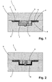
- the casting mold 1 for casting a casting G from a magnesium-treated cast iron melt which is here a brake disk, has a lower outer molded part 2 and an upper, lying on the lower mold part 2 and this covering outer mold part 3.
- a mold cavity 4 is formed, which delimit the outer peripheral surfaces, the outer face of the pot and the outer face of the pot associated friction surface of the friction ring of the brake disc casting G to be produced.
- the other friction surface of the friction ring and the inner peripheral surfaces of the pot of the casting G are imaged by a casting core 5, which is inserted into the mold cavity 4.
- projections 6 which extend into the provided for the friction ring of casting casting G annular portion of the mold cavity 4 and with their free ends in correspondingly shaped, here in detail only hinted recordings of the lower mold part 2 sit.
- the projections 6 form in the casting G radially from the inside of the pot to the outer peripheral surface of the friction ring leading cooling channels.
- the outer mold parts 2, 3 and the casting core 5 with its integrally connected projections 6 are made of a molding material consisting of a sand-like molding base material and an organic resin binder mixing with the molding base material.
- this molding material has been filled and compacted in a manner known per se into a molding box (not shown here). Subsequently, the filled into the molding box molding material has been gassed with SO 2 gas. In this case, a chemical reaction has occurred between the resin binder and the sulfur dioxide gas, through which the resin binder has hardened.
- the dimensionally stable casting moldings (outer moldings 2, 3 and casting core 5 with its projections 6) thus obtained are in contact with their surfaces in contact with the melt (internal surfaces of the molds) Mold cavity 4, outer surfaces of the casting core 5 and its projections 6 and the mold cavity 4 covering portions of the lower mold part 2 associated surface of the upper outer mold part 3) has been coated with a coating applied in the form of a coating 7,8,9, as the sulfide formers calcium carbonate contained.
- the cast iron treated with magnesium immediately prior to entry into the casting mold 1 is poured into the casting mold 1 via the pond, not shown, and flows through channels, also not shown, into the molding cavity 4 until it is completely filled with cast iron.
Landscapes
- Engineering & Computer Science (AREA)
- Mechanical Engineering (AREA)
- Chemical & Material Sciences (AREA)
- Chemical Kinetics & Catalysis (AREA)
- General Chemical & Material Sciences (AREA)
- Mold Materials And Core Materials (AREA)
- Refinement Of Pig-Iron, Manufacture Of Cast Iron, And Steel Manufacture Other Than In Revolving Furnaces (AREA)
Description
- Die Erfindung betrifft ein Verfahren zum Gießen von Gussteilen aus einer Vermicular- oder eine Kugelgrafit bildenden Eisengussschmelze, bei dem die Eisengussschmelze in eine Gießform gegossen wird, die mindestens ein Gießformteil umfasst, das aus einem Formstoff, der aus einem sandartigen Grundstoff und einem organischen Binder gemischt ist, geformt und anschließend mit einem schwefelhaltigen Gas, insbesondere SO2-Gas, begast worden ist, um den Binder des Formstoffs auszuhärten, so dass ein formstabiles Formteil erhalten worden ist.
- Bei den Gießformteilen der voranstehend angegebenen Art handelt es sich in der Praxis typischerweise um so genannte "Gießkerne", mit denen am zu gießenden Gussteil Hohlräume, wie Kanäle, Höhlungen etc., oder Ausnehmungen mit Hinterschneidungen und vergleichbare komplexe Formgebungen abgebildet werden. Beim Entformen des fertig erstarrten Gussteils aus der jeweiligen Gießform werden die betreffenden Gießformteile zerstört. Dabei zerfallen sie in rieselfähige Einzelteile, die sich mechanisch, beispielsweise durch Rütteln, oder mit Hilfe einer Spülflüssigkeit aus dem Gussteil befördern lassen.
- Gießkerne dieser Art werden sowohl in Gießformen verwendet, deren äußere Teile als feste Dauerformen ausgeführt sind, als auch in so genannten "verlorenen Gießformen". Bei verlorenen Gießformen sind nicht nur die Gießkerne, sondern auch die äußeren, den das Gussteil außen umgrenzenden Formteile aus Formstoff hergestellt und werden dementsprechend bei der Entformung des jeweiligen Gussteils ebenfalls vollständig zerstört.
- Es sind verschiedene Möglichkeiten bekannt, verlorene Formteile (Gießkerne und äußere Formteile) für Gießformen herzustellen. Dabei wird unterschieden zwischen den so genannten "Coldbox-Verfahren" und den "Hotbox-Verfahren". Während die Hotbox-Verfahren auf der Verwendung von einen anorganischen Binder enthaltenden Formstoffen beruhen, ist den "Coldbox-Verfahren" gemeinsam, dass der aus einem Formsand und einem organischen Binder gemischte Formstoff nach dem Einfüllen in den das jeweils herzustellende Formteil abbildenden Formkasten mit einem Gas begast wird. Das dabei durch den Formstoff tretende Gas reagiert chemisch mit dem jeweiligen Binder und bewirkt so dessen Aushärtung.
- Eine Variante des Coldbox-Verfahrens ist das SO2-Verfahren. Bei diesem Verfahren ist der jeweils verarbeitete Formstoff aus einem Formsand und einem Harzbinder gemischt, bei dem es sich beispielsweise um einen Furan-Phenol- oder einen Epoxyharz-Binder handeln kann. Während des Begasens eines derart zusammengesetzten Formstoffs mit SO2 härtet der jeweilige Harzbinder durch Reaktion mit der Schwefelsäure aus, die sich aus Schwefeldioxid, Sauerstoff und Wasser bildet.
- Das SO2-Verfahren wird in der Praxis in großem Umfang eingesetzt, da die mit Schwefeldioxid verfestigbaren Formstoffe im unverfestigten Zustand eine gute Fließfähigkeit und damit einhergehend ein besonders gutes Formfüllungsvermögen besitzen. Daher sind diese Formstoffe besonders zur Herstellung von filigran geformten Außenteilen und Kernen für Gießformen geeignet. Darüber hinaus sind die mit Schwefeldioxid verfestigbaren Formstoffe ohne besondere Vorkehrungen lange haltbar und weisen nach der Begasung mit dem Schwefeldioxid-Gas eine hohe Formstabilität auf.
- Praktische Erfahrungen beim Vergießen von Gusseisen in Gießformen, die im SO2-Verfahren hergestellt sind, zeigen allerdings, dass die dabei erhaltenen Gussteile häufig unerwünschte Entartungen des in dem Gussteil gebildeten Grafits aufweisen. Diese Beobachtung betraf insbesondere Gusstücke, die aus einer magnesiumbehandelten Eisenguss-Schmelze gegossen worden sind.
- Wie im Einzelnen beispielsweise in der
EP 1 752 552 B1 beschrieben, kann Gusseisen unmittelbar vor dem Eintritt in die Gießform oder noch in der Gießform selbst einer Magnesiumbehandlung unterzogen werden. Das bei diesem Vorgang zugeführte Magnesium bildet mit anderen Bestandteilen des Gusseisens oder mit ebenfalls zusätzlich zugeführten Elementen Verbindungen, die als Keime für die Entstehung der jeweils gewünschten Grafitform dienen. So lassen sich durch geeignete Zugaben von Magnesium optimierte Gießergebnisse bei der Erzeugung von Kugelgrafit ("GJS"), bei dem der Grafit in einer kugeligen Gestalt vorliegt, oder Vermiculargrafit ("GJV") erzeugen, bei dem der Grafit würmchenartig vorliegt. - Gusseisen mit Kugelgrafit besitzt typische Festigkeiten von 350 MPa bis 1000 MPa, während die Festigkeit von Gusseisen mit Vermiculargrafit im Bereich von 350 MPa bis 500 MPa liegt. Der besondere Vorteil von Vermiculargrafit besteht dabei in einer günstigen Kombination aus hoher Festigkeit und guter Wärmeleitfähigkeit sowie gutem Dämpfungsverhalten. Gusseisen mit lamellenförmig vorliegendem Grafit ("GJL") weist dagegen Festigkeiten im Bereich von 150 MPa bis 350 MPa auf.
- An Gussteilen, die aus GJS oder GJV bildenden magnesiumbehandelten Eisenguss-Schmelzen in Gießformen mit SO2-gehärteten Außenteilen oder Gießkernen gegossenen Gussteilen hergestellt wurden, wurde beobachtet, dass der Grafit in lokal begrenzten, oberflächennahen Abschnitten nicht in der erwarteten Kugel- oder Vermicular-Gestalt vorlag, sondern in Lamellenform. Diese Abweichung von der eigentlich angestrebten Ausbildung des Grafits führt zu lokal stark abweichenden Eigenschaften des Gussteils, wodurch gerade die Qualität von dünnwandigen Bauteilen stark beeinträchtigt werden kann.
- Vor diesem Hintergrund lag der Erfindung die Aufgabe zu Grunde, Möglichkeiten aufzuzeigen, mit denen sich bei Gießformen, die nach dem SO2-Verfahren hergestellt sind, die Gefahr des Auftretens von lokalen Graphit- und Gefügeentartungen am Gussteil beim Vergießen von Kugel- oder Vermiculargrafit bildenden Eisengussschmelze auf ein Minimum reduzieren lassen.
- Diese Aufgabe ist erfindungsgemäß durch das in Anspruch 1 angegebene Verfahren gelöst worden.
- Den in den genannten Ansprüchen angegebenen Varianten der Erfindung liegt der Gedanke zugrunde, mindestens die Fläche eines aus einem sandartigen Grundstoff und einem organischen Binder gemischten und durch Begasung mit schwefelhaltigem Gas, insbesondere SO2-Gas, gehärteten Gießformteils, die beim Eingießen der Metallguss-Schmelze in die unter Verwendung des Formteils zusammengesetzte Gießform mit der Metallguss-Schmelze in Berührung kommt, mit einer einen nicht flüchtigen Sulfidbildner enthaltenden Beschichtung zu versehen.
- Die Erfindung geht von der Erkenntnis aus, dass bei den im Stand der Technik eingesetzten, unter Verwendung von SO2-Gas gehärteten Gießformteilen in Folge der mit dem Eingießen der heißen Schmelze einhergehenden Erwärmung schwefelhaltige Dämpfe oder Gase aus den Gießformteilen austreten und in Richtung des von der Gießform umschlossenen Formhohlraums drängen. Dort treffen sie auf das in den Formhohlraum gefüllte Gussmetall und reagieren mit den in ihm enthaltenen Bestandteilen.
- Diese Reaktionen führen beispielsweise bei magnesiumbehandelten Eisengussschmelzen zur Entstehung von oberflächennah sich ansammelndem Magnesiumsulfid. Das auf diese Weise gebundene Magnesium kann im Gusseisen dann nicht mehr seine keimbildende Wirkung entfalten mit der Folge, dass nicht die gewünschte Grafitform entsteht, sondern eine entartete, deutlich schlechtere mechanische Eigenschaften bedingende Grafitform.
- Bei einer aus erfindungsgemäß beschichteten Teilen zusammengesetzten Gießform ist die Gefahr des Unwirksamwerdens bestimmter Bestandteile des jeweils vergossenen Gussmetalls durch die auf die kritischen Flächen des jeweiligen Gießformteils aufgetragene, einen Sulfidbildner enthaltende Beschichtung gebannt. Bei einem erfindungsgemäß beschichteten Gießformteil trifft das aus dem Gießformteil drängende schwefelhaltige Gas auf die erfindungsgemäß beschaffene Beschichtung und reagiert mit dem in ihr enthaltenen Sulfidbildner zu einem Sulfid. In diesem gebundenen Zustand ist der Schwefel gegenüber der jeweils vergossenen Metallschmelze wirkungslos.
- Die Erfindung nutzt auf diese Weise eine aus der
DE-OS 24 08 344 - So enthält die erfindungsgemäß vorgesehene Beschichtung einen Sulfidbildner, der verhindert, dass das in der erfindungsgemäß vergossenen Schmelze enthaltene Magnesium mit dem aus dem Gießformteil ausgasenden schwefelhaltigen Gas eine Verbindung eingeht.
- Mit der Erfindung ist es somit auf einfache Weise möglich, auch in Gießformen, die unter Verwendung von nach dem SO2-Verfahren hergestellten Gießformteilen zusammengesetzt sind, hochwertige Gussteile zu erzeugen, bei denen die Gefahr des Auftretens von lokalen Gefügeentartungen auf ein Minimum reduziert ist.
- Praktische Versuche haben dabei ergeben, dass sich die Erfindung insbesondere im Zusammenhang mit dem Vergießen von Kugel- oder Vermiculargrafit bildenden Eisenguss-Schmelzen positiv auswirkt. So konnte gezeigt werden, dass es nach dem Auftrag der erfindungsgemäß zusammengesetzten Beschichtung auf die mit der jeweils vergossenen Eisenguss-Schmelze in Kontakt kommenden Flächen der Gießform auch dann zu keinen Gefügeentartungen kommt, wenn die Eisenguss-Schmelze vergleichbar hohe Magnesium-Gehalte in Folge einer Behandlung mit einem magnesiumhaltigen Mittel unterzogen worden ist.
- Als besonders praxisgerecht hat es sich in diesem Zusammengang herausgestellt, wenn die in erfindungsgemäßer Weise auf das jeweilige Gießformteil aufgetragene Beschichtung als Sulfidbildner ein Alkalicarbonat oder Erdalkalicarbonat enthält. In praktischen Versuchen besonders bewährt haben sich erfindungsgemäß aufgetragene und beschaffene Beschichtungen, wenn sie Calciumcarbonat (CaCO3) enthielten, das mit dem Schwefel zu CaS reagiert.
- Die aus den Alkali- bzw. Erdalkalicarbonaten gebildeten Sulfide verhalten sich insbesondere dann, wenn als Gussmetall eine Eisenguss-Schmelze vergossen wird, einerseits neutral und binden andererseits den aus dem Formstoff während des Gießvorgangs ausgasenden, in Richtung des Formhohlraums der jeweiligen Gießform vordrängenden Schwefel, so dass dieser keinen Einfluss mehr auf die Bestandteile der jeweils vergossenen Metallschmelze ausüben kann.
- Denkbar ist es auch, wenn die erfindungsgemäß aufgetragene Beschichtung als Sulfidbildner ein Alkalihydrogencarbonat, z. B. Natriumhydrogencarbonat (NaHCO3), enthält. Diese Stoffe bilden mit dem aus dem Gießformteil austretenden Schwefel ebenfalls Sulfide, wie beispielsweise NaO2S und verhindern so, dass der Schwefel mit einem Bestandteil des jeweils vergossenen Gussmetalls reagieren kann.
- Des weiteren kann es sich bei dem in einer erfindungsgemäßen Beschichtung enthaltenen Sulfidbildner um Amoniumcarbonat oder Amoniumhydrogencarbonat handeln. Diese Stoffe bilden mit Schwefel Amoniumsulfide.
- Grundsätzlich ist es vorteilhaft, wenn die mit der jeweiligen Metallschmelze in Berührung kommenden Flächen aller im SO2-Verfahren erzeugten Gießformteile in der erfindungsgemäßen Weise beschichtet werden. Bei vollständig als verlorene Form ausgebildeten Gießformen bezieht dies also auch die Außenteile der Gießform ein, durch die der Formhohlraum der Gussform an seinen Außenseiten umgrenzt wird.
- Besonders vorteilhaft wirkt sich die Erfindung jedoch dann aus, wenn es sich bei dem erfindungsgemäß beschichteten Gießformteil um einen Gießkern handelt. Solche Gießkerne werden in der Regel vom in die Gießform eingegossenen Metall im Wesentlichen vollständig umgeben, so dass das aus dem Kern austretende Gas das anliegende Gussmaterial stark penetriert.
- Nachfolgend wird die Erfindung anhand einer Ausführungsbeispiele darstellenden Zeichnung näher erläutert. Es zeigen jeweils schematisch:
- Fig. 1
- eine Gießform im ungefüllten Zustand in einem Querschnitt;
- Fig. 2
- die Gießform im gefüllten Zustand.
- Die Gießform 1 zum Gießen eines Gussteils G aus einer magnesiumbehandelten Eisenguss-Schmelze, bei dem es sich hier um eine Bremsscheibe handelt, weist ein unteres äußeres Formteil 2 und ein oberes, auf dem unteren Formteil 2 aufliegendes und dieses abdeckendes äußeres Formteil 3 auf.
- In das Formteil 2 ist von seiner dem oberen Formteil 3 zugeordneten Fläche her ein Formhohlraum 4 eingeformt, der die äußeren Umfangsflächen, die äußere Stirnfläche des Topfes sowie die der äußeren Stirnfläche des Topfes zugeordnete Reibfläche des Reibrings des zu erzeugenden Bremsscheiben-Gussteils G abgrenzen. Die andere Reibfläche des Reibrings sowie die Innenumfangsflächen des Topfes des Gussteils G werden durch einen Gießkern 5 abgebildet, der in den Formhohlraum 4 eingesetzt ist.
- An den Gießkern 5 sind sternförmig um seinen Umfang in gleichen Winkelabständen verteilte Vorsprünge 6 angeformt, die in den für den Reibring des zu gießenden Gussteils G vorgesehenen ringförmigen Abschnitt des Formhohlraums 4 reichen und mit ihren freien Enden in entsprechend geformte, hier im Einzelnen nur angedeutete Aufnahmen des unteren Formteils 2 sitzen. Die Vorsprünge 6 bilden im Gussteil G radial von der Innenseite von dessen Topf zur äußeren Umfangsfläche des Reibrings führende Kühlkanäle aus.
- Die äußeren Formteile 2,3 und der Gießkern 5 mit seinen einstückig mit ihm verbundenen Vorsprüngen 6 sind aus einem Formstoff hergestellt, der aus einem sandförmigen Formgrundstoff und einem sich mit dem Formgrundstoff vermischenden organischen Harzbinder besteht. Zur Herstellung der Formteile 2,3 und des Gießkerns 5 mit den Vorsprüngen 6 ist dieser Formstoff in an sich bekannter Weise in jeweils einen hier nicht gezeigten Formkasten gefüllt und verdichtet worden. Anschließend ist der in den Formkasten gefüllte Formstoff mit SO2-Gas begast worden. Dabei ist es zu einer chemischen Reaktion zwischen dem Harzbinder und dem Schwefeldioxid-Gas gekommen, durch den der Harzbinder ausgehärtet ist.
- Nach Abschluss der Aushärtung sind die so erhaltenen formstabilen Gießformteile (äußere Formteile 2,3 und Gießkern 5 mit seinen Vorsprüngen 6) auf ihren mit der Schmelze in Berührung kommenden Flächen (Innenflächen des Formhohlraums 4, Außenflächen des Gießkerns 5 und seiner Vorsprünge 6 sowie den Formhohlraum 4 abdeckende Abschnitte der dem unteren Formteil 2 zugeordneten Fläche des oberen äußeren Formteils 3) mit einer in Form einer Schlichte aufgetragenen Beschichtung 7,8,9 beschichtet worden, die als Sulfidbildner Calciumcarbonat enthielt.
- Zur Herstellung des Gussteils G wird das unmittelbar vor dem Eintritt in die Gießform 1 mit Magnesium behandelte Gusseisen über den nicht dargestellten Tümpel in die Gießform 1 gegossen und fließt über ebenfalls nicht dargestellte Kanäle in den Formhohlraum 4, bis dieser vollständig mit Gusseisen gefüllt ist.
- Einhergehend mit dem Eintritt des Gusseisens in die Gießform 1 kommt es zu einer starken Erwärmung der mit dem Gusseisen in Kontakt kommenden Bereiche der Gießform 1. In Folge dieser Erwärmung aufgrund von in den Gießformteilen 2,3 und 5 unvermeidbar vorhandener Restfeuchte sich bildende schwefelhaltige Dämpfe breiten sich daraufhin in der Gießform 1 aus und drängen dabei auch in Richtung des Formhohlraums 4.
- Dort treffen sie auf die CaCO3 als Sulfidbildner enthaltende Beschichtung 7,8,9. Der Schwefel reagiert daraufhin mit dem CaCO3 zu CaS und wird in der Beschichtung 7 gebunden. Die Penetration des in den Formhohlraum gefüllten Gusseisens mit Schwefel ist auf diese Weise wirkungsvoll unterbunden, so dass das Gusseisen über sein gesamtes Volumen unter Ausbildung der gewünschten Grafitform gleichmäßig erstarren kann. Die Gefahr der Entstehung entarteten Grafits besteht damit nicht mehr.
-
- 1
- Gießform
- 2
- unteres äußeres Formteil der Gießform 1
- 3
- oberes äußeres Formteil der Gießform 1
- 4
- Formhohlraum
- 5
- Gießkern
- 6
- Vorsprünge
- 7,8,9
- einen Sulfidbildner enthaltende Beschichtung
- G
- Gussteil
Claims (9)
- Verfahren zum Gießen von Gussteilen (G) aus einer Vermicular- oder eine Kugelgrafit bildenden Eisengussschmelze, bei dem die Eisengussschmelze in eine Gießform (1) gegossen wird, die mindestens ein Gießformteil (2,3,5) umfasst, das aus einem Formstoff, der aus einem sandartigen Grundstoff und einem organischen Binder gemischt ist, geformt und anschließend mit einem schwefelhaltigen Gas, insbesondere SO2-Gas, begast worden ist, um den Binder des Formstoffs auszuhärten, so dass ein formstabiles Formteil (2,3,5) erhalten worden ist, dadurch gekennzeichnet, dass nach dem Aushärten des Formteils (2,3,5) und vor dem Vergießen der Eisengussschmelze mindestens eine der Flächen, die beim Eingießen der Eisengussschmelze in die Gießform (1) mit der Eisengussschmelze in Berührung kommt, mit einer einen nicht flüchtigen Sulfidbildner enthaltenden Beschichtung (7,8,9) versehen wird.
- Verfahren nach Anspruch 1, dadurch gekenzeichnet, dass der Sulfidbildner ein Alkalicarbonat ist.
- Verfahren oder Gießform nach Anspruch 1, dadurch gekennzeichnet, dass der Sulfidbildner ein Erdalkalicarbonat ist.
- Verfahren oder Gießform nach Anspruch 3, dadurch gekennzeichnet, dass das Erdalkalicarbonat Calciumcarbonat ist.
- Verfahren nach Anspruch 1, dadurch gekennzeichnet, dass der Sulfidbildner ein Alkalihydrogencarbonat ist.
- Verfahren nach Anspruch 1, dadurch gekennzeichnet, dass der Sulfidbildner Amoniumcarbonat ist.
- Verfahren nach Anspruch 1, dadurch gekennzeichnet, dass der Sulfidbildner Amoniumhydrogencarbonat ist.
- Verfahren nach einem der voranstehenden Ansprüche, dadurch gekennzeichnet, dass das Formteil ein Gießkern (5) ist.
- Verfahren nach einem der voranstehenden Ansprüche, dadurch gekennzeichnet, dass die Eisenguss-Schmelze einer Magnesium-Behandlung unterzogen wird.
Applications Claiming Priority (2)
| Application Number | Priority Date | Filing Date | Title |
|---|---|---|---|
| DE102007031448A DE102007031448A1 (de) | 2007-07-05 | 2007-07-05 | Verfahren zum Herstellen von Formteilen für Gießformen, Gießform und Verfahren zum Vergießen einer Metallschmelze |
| PCT/EP2008/058723 WO2009004090A1 (de) | 2007-07-05 | 2008-07-04 | VERFAHREN ZUM VERGIEßEN EINER METALLSCHMELZE |
Publications (2)
| Publication Number | Publication Date |
|---|---|
| EP2176018A1 EP2176018A1 (de) | 2010-04-21 |
| EP2176018B1 true EP2176018B1 (de) | 2011-04-06 |
Family
ID=39764823
Family Applications (1)
| Application Number | Title | Priority Date | Filing Date |
|---|---|---|---|
| EP08774799A Not-in-force EP2176018B1 (de) | 2007-07-05 | 2008-07-04 | VERFAHREN ZUM VERGIEßEN EINER METALLSCHMELZE |
Country Status (8)
| Country | Link |
|---|---|
| US (1) | US8327909B2 (de) |
| EP (1) | EP2176018B1 (de) |
| AT (1) | ATE504372T1 (de) |
| BR (1) | BRPI0812881B1 (de) |
| DE (2) | DE102007031448A1 (de) |
| ES (1) | ES2361381T3 (de) |
| MX (1) | MX2009007385A (de) |
| WO (1) | WO2009004090A1 (de) |
Families Citing this family (7)
| Publication number | Priority date | Publication date | Assignee | Title |
|---|---|---|---|---|
| DE102008025311A1 (de) * | 2008-05-27 | 2009-12-03 | Ashland-Südchemie-Kernfest GmbH | Geruchs- und schadstoffadsorbierende Beschichtungsmasse für den kastengebundenen Metallguss |
| DE102010047952A1 (de) * | 2010-10-08 | 2012-04-12 | Continental Automotive Gmbh | Verfahren zur Herstellung eines Gehäuses, insbesondere eines Gehäuses eines Turboladers |
| DE102014220632A1 (de) | 2014-10-10 | 2016-04-14 | Hüttenes-Albertus Chemische Werke GmbH | Verwendung einer basischen Zusammensetzung als Infiltrationsmittel für den Formstoff einer Gießform zur Vermeidung von weißen Belägen |
| CN104439205A (zh) * | 2014-11-28 | 2015-03-25 | 常熟市勤丰铸件厂 | 一种铸件浇铸工艺方法 |
| DE102016211930A1 (de) | 2016-06-30 | 2018-01-04 | Wobben Properties Gmbh | Schlichtezusammensetzung zur Herstellung von Formüberzügen auf verlorenen Formen bzw. auf Kernen für den Eisen- und Stahlguss |
| CN106077470A (zh) * | 2016-08-26 | 2016-11-09 | 重庆新红旗缸盖制造有限公司 | 蠕铁发动机缸盖浇注工艺 |
| DE102019002802A1 (de) * | 2019-04-16 | 2020-10-22 | Ask Chemicals Gmbh | Schlichtezusammensetzung, Verfahren zur Beschichtung einer Gießform, Verwendung der Schlichtezusammensetzung zur Beschichtung einer Gießform und Gießform |
Family Cites Families (8)
| Publication number | Priority date | Publication date | Assignee | Title |
|---|---|---|---|---|
| US2786771A (en) * | 1952-07-07 | 1957-03-26 | Eaton Mfg Co | Core wash |
| GB1415395A (en) * | 1973-02-20 | 1975-11-26 | White Sea & Baltic Co | Foundry moulds and cores |
| JPS55149747A (en) | 1979-05-12 | 1980-11-21 | Sogo Imono Center | Preventing method for defect of spheroidal graphite cast iron casting |
| JPS57171540A (en) | 1981-04-17 | 1982-10-22 | Mitsubishi Heavy Ind Ltd | Preventing method for sulfurization of cast steel casting |
| US4550761A (en) * | 1982-11-03 | 1985-11-05 | Moore William H | Mold coating |
| JPS5994550A (ja) | 1982-11-19 | 1984-05-31 | Kawasaki Steel Corp | 球状化黒鉛鋳鉄鋳物の表層黒鉛組織の劣化防止方法 |
| JPS6040644A (ja) | 1983-08-12 | 1985-03-04 | Kawasaki Heavy Ind Ltd | 球状黒鉛鋳鉄用塗型剤 |
| EP1752552B1 (de) | 2005-08-05 | 2007-03-28 | Fritz Winter Eisengiesserei GmbH & Co. KG | Verfahren zum Herstellen von Vermikulargraphitguss |
-
2007
- 2007-07-05 DE DE102007031448A patent/DE102007031448A1/de not_active Withdrawn
-
2008
- 2008-07-04 MX MX2009007385A patent/MX2009007385A/es active IP Right Grant
- 2008-07-04 AT AT08774799T patent/ATE504372T1/de active
- 2008-07-04 BR BRPI0812881A patent/BRPI0812881B1/pt not_active IP Right Cessation
- 2008-07-04 WO PCT/EP2008/058723 patent/WO2009004090A1/de active Application Filing
- 2008-07-04 EP EP08774799A patent/EP2176018B1/de not_active Not-in-force
- 2008-07-04 ES ES08774799T patent/ES2361381T3/es active Active
- 2008-07-04 DE DE502008003125T patent/DE502008003125D1/de active Active
- 2008-07-04 US US12/529,683 patent/US8327909B2/en not_active Expired - Fee Related
Also Published As
| Publication number | Publication date |
|---|---|
| ATE504372T1 (de) | 2011-04-15 |
| EP2176018A1 (de) | 2010-04-21 |
| DE502008003125D1 (de) | 2011-05-19 |
| US20100155010A1 (en) | 2010-06-24 |
| WO2009004090A1 (de) | 2009-01-08 |
| DE102007031448A1 (de) | 2009-01-15 |
| BRPI0812881A2 (pt) | 2014-12-09 |
| MX2009007385A (es) | 2009-07-17 |
| BRPI0812881B1 (pt) | 2016-04-26 |
| US8327909B2 (en) | 2012-12-11 |
| ES2361381T3 (es) | 2011-06-16 |
Similar Documents
| Publication | Publication Date | Title |
|---|---|---|
| EP2176018B1 (de) | VERFAHREN ZUM VERGIEßEN EINER METALLSCHMELZE | |
| DE69917172T2 (de) | Exothermer Körper für Giessereizwecke | |
| DE1936153B2 (de) | Verfahren und giessform zum herstellen von gusstuecken mit kugelgraphit | |
| DE102005009025B4 (de) | Gussform und Verfahren zum Gießen zum Erzielen einer Modifikation eines Gussmetalls innerhalb einer Form | |
| EP1934002B1 (de) | Kerne sowie ein verfahren zur herstellung von kernen | |
| DE2109553A1 (de) | Formkerne fur Hochtemperatur und Druckformen und Verfahren zur Herstellung derartiger Materialien | |
| DE102005019699B3 (de) | Verfahren zur Herstellung eines dreidimensionalen Gegenstandes aus Metallsalz-Partikeln, sowie damit hergestellter Gegenstand | |
| DE102018109620A1 (de) | Sandkern zur eliminierung von oberflächenzerfall | |
| DE1198496B (de) | Verfahren zur Herstellung von Gussstuecken mit feinkoernigem Kristallgefuege | |
| EP0143954B1 (de) | Verfahren zum Herstellen von Formteilen nach dem Coldbox-Verfahren sowie Formwerkzeug | |
| DE1097089B (de) | Fuer die Verwendung im Praezisionsgiessverfahren als Modellmaterial geeignetes Wachs | |
| DE102004034802B4 (de) | Metallische Dauerform zur Herstellung von Großgussteilen aus Metalllegierungen | |
| DE102017111846A1 (de) | Verfahren zur Herstellung von lokal modifizierten Gussformteilen | |
| DE19535444C2 (de) | Verfahren zum pulvermetallurgischen Herstellen von Gegenständen sowie auf diese Weise hergestellte Gegenstände | |
| JPH0371950A (ja) | 崩壊性中子の中間層形成用スラリー及びこれを用いた崩壊性中子の製造方法並びにこれにより製造された崩壊性中子 | |
| DE3516033A1 (de) | Verfahren und speiserform zum herstellen eines einen gekruemmten speiserkanal aufweisenden speisereinsatzes, insbesondere seitenspeisereinsatzes | |
| DE102005023051A1 (de) | Gießform zum Gießen von Metallschmelze | |
| DE10209183A1 (de) | Formstoff für die Herstellung von Gießformteilen | |
| DE102022106807A1 (de) | Speiser und Speisersystem für Gießformen | |
| WO2004098811A1 (de) | Formstoff, formteil und verfahren zur herstellung von formteilen für eine giessform | |
| DE19751929A1 (de) | Verfahren zum Herstellen eines Gußstücks | |
| DE1198495B (de) | Verfahren zur Herstellung einer nach dem Abgiessen leicht zerfallenden, durch Wasserglas gebundenen und durch Kohlensaeure aushaertbaren Form- oder Kernmasse | |
| DE2100097C3 (de) | Verfahren zum Herstellen von Gießformteilen | |
| DE4103802A1 (de) | Giessform | |
| DE102007001780A1 (de) | Verfahren zur Herstellung von faserverstärkten Druckgiessteilen |
Legal Events
| Date | Code | Title | Description |
|---|---|---|---|
| PUAI | Public reference made under article 153(3) epc to a published international application that has entered the european phase |
Free format text: ORIGINAL CODE: 0009012 |
|
| 17P | Request for examination filed |
Effective date: 20090923 |
|
| AK | Designated contracting states |
Kind code of ref document: A1 Designated state(s): AT BE BG CH CY CZ DE DK EE ES FI FR GB GR HR HU IE IS IT LI LT LU LV MC MT NL NO PL PT RO SE SI SK TR |
|
| AX | Request for extension of the european patent |
Extension state: AL BA MK RS |
|
| DAX | Request for extension of the european patent (deleted) | ||
| GRAP | Despatch of communication of intention to grant a patent |
Free format text: ORIGINAL CODE: EPIDOSNIGR1 |
|
| GRAS | Grant fee paid |
Free format text: ORIGINAL CODE: EPIDOSNIGR3 |
|
| GRAA | (expected) grant |
Free format text: ORIGINAL CODE: 0009210 |
|
| AK | Designated contracting states |
Kind code of ref document: B1 Designated state(s): AT BE BG CH CY CZ DE DK EE ES FI FR GB GR HR HU IE IS IT LI LT LU LV MC MT NL NO PL PT RO SE SI SK TR |
|
| REG | Reference to a national code |
Ref country code: GB Ref legal event code: FG4D Free format text: NOT ENGLISH |
|
| REG | Reference to a national code |
Ref country code: CH Ref legal event code: EP |
|
| REG | Reference to a national code |
Ref country code: IE Ref legal event code: FG4D |
|
| REF | Corresponds to: |
Ref document number: 502008003125 Country of ref document: DE Date of ref document: 20110519 Kind code of ref document: P |
|
| REG | Reference to a national code |
Ref country code: DE Ref legal event code: R096 Ref document number: 502008003125 Country of ref document: DE Effective date: 20110519 |
|
| REG | Reference to a national code |
Ref country code: ES Ref legal event code: FG2A Ref document number: 2361381 Country of ref document: ES Kind code of ref document: T3 Effective date: 20110616 |
|
| REG | Reference to a national code |
Ref country code: NL Ref legal event code: T3 |
|
| REG | Reference to a national code |
Ref country code: SE Ref legal event code: TRGR |
|
| PG25 | Lapsed in a contracting state [announced via postgrant information from national office to epo] |
Ref country code: SI Free format text: LAPSE BECAUSE OF FAILURE TO SUBMIT A TRANSLATION OF THE DESCRIPTION OR TO PAY THE FEE WITHIN THE PRESCRIBED TIME-LIMIT Effective date: 20110406 |
|
| LTIE | Lt: invalidation of european patent or patent extension |
Effective date: 20110406 |
|
| REG | Reference to a national code |
Ref country code: IE Ref legal event code: FD4D |
|
| PG25 | Lapsed in a contracting state [announced via postgrant information from national office to epo] |
Ref country code: LT Free format text: LAPSE BECAUSE OF FAILURE TO SUBMIT A TRANSLATION OF THE DESCRIPTION OR TO PAY THE FEE WITHIN THE PRESCRIBED TIME-LIMIT Effective date: 20110406 Ref country code: PT Free format text: LAPSE BECAUSE OF FAILURE TO SUBMIT A TRANSLATION OF THE DESCRIPTION OR TO PAY THE FEE WITHIN THE PRESCRIBED TIME-LIMIT Effective date: 20110808 Ref country code: NO Free format text: LAPSE BECAUSE OF FAILURE TO SUBMIT A TRANSLATION OF THE DESCRIPTION OR TO PAY THE FEE WITHIN THE PRESCRIBED TIME-LIMIT Effective date: 20110706 Ref country code: HR Free format text: LAPSE BECAUSE OF FAILURE TO SUBMIT A TRANSLATION OF THE DESCRIPTION OR TO PAY THE FEE WITHIN THE PRESCRIBED TIME-LIMIT Effective date: 20110406 |
|
| PG25 | Lapsed in a contracting state [announced via postgrant information from national office to epo] |
Ref country code: IS Free format text: LAPSE BECAUSE OF FAILURE TO SUBMIT A TRANSLATION OF THE DESCRIPTION OR TO PAY THE FEE WITHIN THE PRESCRIBED TIME-LIMIT Effective date: 20110806 Ref country code: CY Free format text: LAPSE BECAUSE OF FAILURE TO SUBMIT A TRANSLATION OF THE DESCRIPTION OR TO PAY THE FEE WITHIN THE PRESCRIBED TIME-LIMIT Effective date: 20110406 Ref country code: GR Free format text: LAPSE BECAUSE OF FAILURE TO SUBMIT A TRANSLATION OF THE DESCRIPTION OR TO PAY THE FEE WITHIN THE PRESCRIBED TIME-LIMIT Effective date: 20110707 Ref country code: LV Free format text: LAPSE BECAUSE OF FAILURE TO SUBMIT A TRANSLATION OF THE DESCRIPTION OR TO PAY THE FEE WITHIN THE PRESCRIBED TIME-LIMIT Effective date: 20110406 Ref country code: FI Free format text: LAPSE BECAUSE OF FAILURE TO SUBMIT A TRANSLATION OF THE DESCRIPTION OR TO PAY THE FEE WITHIN THE PRESCRIBED TIME-LIMIT Effective date: 20110406 |
|
| PG25 | Lapsed in a contracting state [announced via postgrant information from national office to epo] |
Ref country code: MT Free format text: LAPSE BECAUSE OF FAILURE TO SUBMIT A TRANSLATION OF THE DESCRIPTION OR TO PAY THE FEE WITHIN THE PRESCRIBED TIME-LIMIT Effective date: 20110406 |
|
| BERE | Be: lapsed |
Owner name: FRITZ WINTER EISENGIESSEREI G.M.B.H. & CO. KG Effective date: 20110731 |
|
| PG25 | Lapsed in a contracting state [announced via postgrant information from national office to epo] |
Ref country code: IE Free format text: LAPSE BECAUSE OF FAILURE TO SUBMIT A TRANSLATION OF THE DESCRIPTION OR TO PAY THE FEE WITHIN THE PRESCRIBED TIME-LIMIT Effective date: 20110406 Ref country code: EE Free format text: LAPSE BECAUSE OF FAILURE TO SUBMIT A TRANSLATION OF THE DESCRIPTION OR TO PAY THE FEE WITHIN THE PRESCRIBED TIME-LIMIT Effective date: 20110406 Ref country code: CZ Free format text: LAPSE BECAUSE OF FAILURE TO SUBMIT A TRANSLATION OF THE DESCRIPTION OR TO PAY THE FEE WITHIN THE PRESCRIBED TIME-LIMIT Effective date: 20110406 |
|
| PLBE | No opposition filed within time limit |
Free format text: ORIGINAL CODE: 0009261 |
|
| STAA | Information on the status of an ep patent application or granted ep patent |
Free format text: STATUS: NO OPPOSITION FILED WITHIN TIME LIMIT |
|
| PG25 | Lapsed in a contracting state [announced via postgrant information from national office to epo] |
Ref country code: DK Free format text: LAPSE BECAUSE OF FAILURE TO SUBMIT A TRANSLATION OF THE DESCRIPTION OR TO PAY THE FEE WITHIN THE PRESCRIBED TIME-LIMIT Effective date: 20110406 Ref country code: SK Free format text: LAPSE BECAUSE OF FAILURE TO SUBMIT A TRANSLATION OF THE DESCRIPTION OR TO PAY THE FEE WITHIN THE PRESCRIBED TIME-LIMIT Effective date: 20110406 Ref country code: MC Free format text: LAPSE BECAUSE OF NON-PAYMENT OF DUE FEES Effective date: 20110731 Ref country code: PL Free format text: LAPSE BECAUSE OF FAILURE TO SUBMIT A TRANSLATION OF THE DESCRIPTION OR TO PAY THE FEE WITHIN THE PRESCRIBED TIME-LIMIT Effective date: 20110406 Ref country code: RO Free format text: LAPSE BECAUSE OF FAILURE TO SUBMIT A TRANSLATION OF THE DESCRIPTION OR TO PAY THE FEE WITHIN THE PRESCRIBED TIME-LIMIT Effective date: 20110406 |
|
| 26N | No opposition filed |
Effective date: 20120110 |
|
| PG25 | Lapsed in a contracting state [announced via postgrant information from national office to epo] |
Ref country code: BE Free format text: LAPSE BECAUSE OF NON-PAYMENT OF DUE FEES Effective date: 20110731 |
|
| REG | Reference to a national code |
Ref country code: DE Ref legal event code: R097 Ref document number: 502008003125 Country of ref document: DE Effective date: 20120110 |
|
| REG | Reference to a national code |
Ref country code: CH Ref legal event code: PL |
|
| PG25 | Lapsed in a contracting state [announced via postgrant information from national office to epo] |
Ref country code: CH Free format text: LAPSE BECAUSE OF NON-PAYMENT OF DUE FEES Effective date: 20120731 Ref country code: LI Free format text: LAPSE BECAUSE OF NON-PAYMENT OF DUE FEES Effective date: 20120731 |
|
| PG25 | Lapsed in a contracting state [announced via postgrant information from national office to epo] |
Ref country code: LU Free format text: LAPSE BECAUSE OF NON-PAYMENT OF DUE FEES Effective date: 20110704 |
|
| PG25 | Lapsed in a contracting state [announced via postgrant information from national office to epo] |
Ref country code: BG Free format text: LAPSE BECAUSE OF FAILURE TO SUBMIT A TRANSLATION OF THE DESCRIPTION OR TO PAY THE FEE WITHIN THE PRESCRIBED TIME-LIMIT Effective date: 20110706 |
|
| PG25 | Lapsed in a contracting state [announced via postgrant information from national office to epo] |
Ref country code: HU Free format text: LAPSE BECAUSE OF FAILURE TO SUBMIT A TRANSLATION OF THE DESCRIPTION OR TO PAY THE FEE WITHIN THE PRESCRIBED TIME-LIMIT Effective date: 20110406 |
|
| REG | Reference to a national code |
Ref country code: AT Ref legal event code: MM01 Ref document number: 504372 Country of ref document: AT Kind code of ref document: T Effective date: 20130704 |
|
| PG25 | Lapsed in a contracting state [announced via postgrant information from national office to epo] |
Ref country code: AT Free format text: LAPSE BECAUSE OF NON-PAYMENT OF DUE FEES Effective date: 20130704 |
|
| REG | Reference to a national code |
Ref country code: FR Ref legal event code: PLFP Year of fee payment: 9 |
|
| REG | Reference to a national code |
Ref country code: FR Ref legal event code: PLFP Year of fee payment: 10 |
|
| REG | Reference to a national code |
Ref country code: FR Ref legal event code: PLFP Year of fee payment: 11 |
|
| PGFP | Annual fee paid to national office [announced via postgrant information from national office to epo] |
Ref country code: TR Payment date: 20180622 Year of fee payment: 11 |
|
| PGFP | Annual fee paid to national office [announced via postgrant information from national office to epo] |
Ref country code: FR Payment date: 20180723 Year of fee payment: 11 Ref country code: IT Payment date: 20180720 Year of fee payment: 11 Ref country code: ES Payment date: 20180829 Year of fee payment: 11 Ref country code: NL Payment date: 20180723 Year of fee payment: 11 Ref country code: DE Payment date: 20180725 Year of fee payment: 11 |
|
| PGFP | Annual fee paid to national office [announced via postgrant information from national office to epo] |
Ref country code: SE Payment date: 20180725 Year of fee payment: 11 Ref country code: GB Payment date: 20180725 Year of fee payment: 11 |
|
| REG | Reference to a national code |
Ref country code: DE Ref legal event code: R119 Ref document number: 502008003125 Country of ref document: DE |
|
| REG | Reference to a national code |
Ref country code: SE Ref legal event code: EUG |
|
| GBPC | Gb: european patent ceased through non-payment of renewal fee |
Effective date: 20190704 |
|
| PG25 | Lapsed in a contracting state [announced via postgrant information from national office to epo] |
Ref country code: NL Free format text: LAPSE BECAUSE OF NON-PAYMENT OF DUE FEES Effective date: 20190801 Ref country code: DE Free format text: LAPSE BECAUSE OF NON-PAYMENT OF DUE FEES Effective date: 20200201 Ref country code: SE Free format text: LAPSE BECAUSE OF NON-PAYMENT OF DUE FEES Effective date: 20190705 Ref country code: GB Free format text: LAPSE BECAUSE OF NON-PAYMENT OF DUE FEES Effective date: 20190704 |
|
| REG | Reference to a national code |
Ref country code: NL Ref legal event code: MM Effective date: 20190801 |
|
| PG25 | Lapsed in a contracting state [announced via postgrant information from national office to epo] |
Ref country code: FR Free format text: LAPSE BECAUSE OF NON-PAYMENT OF DUE FEES Effective date: 20190731 |
|
| PG25 | Lapsed in a contracting state [announced via postgrant information from national office to epo] |
Ref country code: IT Free format text: LAPSE BECAUSE OF NON-PAYMENT OF DUE FEES Effective date: 20190704 |
|
| REG | Reference to a national code |
Ref country code: ES Ref legal event code: FD2A Effective date: 20201126 |
|
| PG25 | Lapsed in a contracting state [announced via postgrant information from national office to epo] |
Ref country code: ES Free format text: LAPSE BECAUSE OF NON-PAYMENT OF DUE FEES Effective date: 20190705 |
|
| PG25 | Lapsed in a contracting state [announced via postgrant information from national office to epo] |
Ref country code: TR Free format text: LAPSE BECAUSE OF NON-PAYMENT OF DUE FEES Effective date: 20200704 |