EP2175702B2 - Buse pour une torche à plasma refroidie par liquide, coiffe de tuyère pour une torche à plasma et tête de torche à plasma dotée de celle-ci - Google Patents
Buse pour une torche à plasma refroidie par liquide, coiffe de tuyère pour une torche à plasma et tête de torche à plasma dotée de celle-ci Download PDFInfo
- Publication number
- EP2175702B2 EP2175702B2 EP09011322.6A EP09011322A EP2175702B2 EP 2175702 B2 EP2175702 B2 EP 2175702B2 EP 09011322 A EP09011322 A EP 09011322A EP 2175702 B2 EP2175702 B2 EP 2175702B2
- Authority
- EP
- European Patent Office
- Prior art keywords
- nozzle
- liquid supply
- section
- case
- groove
- Prior art date
- Legal status (The legal status is an assumption and is not a legal conclusion. Google has not performed a legal analysis and makes no representation as to the accuracy of the status listed.)
- Active
Links
- 239000000110 cooling liquid Substances 0.000 claims description 87
- 239000007788 liquid Substances 0.000 claims description 76
- 239000002826 coolant Substances 0.000 description 57
- 239000007789 gas Substances 0.000 description 23
- 238000001816 cooling Methods 0.000 description 13
- 238000005520 cutting process Methods 0.000 description 11
- XLYOFNOQVPJJNP-UHFFFAOYSA-N water Substances O XLYOFNOQVPJJNP-UHFFFAOYSA-N 0.000 description 11
- 230000007704 transition Effects 0.000 description 8
- 239000012530 fluid Substances 0.000 description 6
- 239000000463 material Substances 0.000 description 5
- 240000006829 Ficus sundaica Species 0.000 description 4
- 238000013021 overheating Methods 0.000 description 4
- RYGMFSIKBFXOCR-UHFFFAOYSA-N Copper Chemical compound [Cu] RYGMFSIKBFXOCR-UHFFFAOYSA-N 0.000 description 3
- 239000003570 air Substances 0.000 description 3
- QVGXLLKOCUKJST-UHFFFAOYSA-N atomic oxygen Chemical compound [O] QVGXLLKOCUKJST-UHFFFAOYSA-N 0.000 description 3
- 239000004020 conductor Substances 0.000 description 3
- 229910052802 copper Inorganic materials 0.000 description 3
- 239000010949 copper Substances 0.000 description 3
- 238000002845 discoloration Methods 0.000 description 3
- 239000001301 oxygen Substances 0.000 description 3
- 229910052760 oxygen Inorganic materials 0.000 description 3
- 238000003466 welding Methods 0.000 description 3
- XKRFYHLGVUSROY-UHFFFAOYSA-N Argon Chemical compound [Ar] XKRFYHLGVUSROY-UHFFFAOYSA-N 0.000 description 2
- IJGRMHOSHXDMSA-UHFFFAOYSA-N Atomic nitrogen Chemical compound N#N IJGRMHOSHXDMSA-UHFFFAOYSA-N 0.000 description 2
- 229910001369 Brass Inorganic materials 0.000 description 2
- 239000010951 brass Substances 0.000 description 2
- 230000007797 corrosion Effects 0.000 description 2
- 238000005260 corrosion Methods 0.000 description 2
- 239000001257 hydrogen Substances 0.000 description 2
- 229910052739 hydrogen Inorganic materials 0.000 description 2
- 230000001590 oxidative effect Effects 0.000 description 2
- 238000007789 sealing Methods 0.000 description 2
- 230000008646 thermal stress Effects 0.000 description 2
- 230000001154 acute effect Effects 0.000 description 1
- 230000002528 anti-freeze Effects 0.000 description 1
- 229910052786 argon Inorganic materials 0.000 description 1
- 125000004429 atom Chemical group 0.000 description 1
- 230000000694 effects Effects 0.000 description 1
- 238000002474 experimental method Methods 0.000 description 1
- 229910052735 hafnium Inorganic materials 0.000 description 1
- VBJZVLUMGGDVMO-UHFFFAOYSA-N hafnium atom Chemical compound [Hf] VBJZVLUMGGDVMO-UHFFFAOYSA-N 0.000 description 1
- 125000004435 hydrogen atom Chemical class [H]* 0.000 description 1
- 238000011835 investigation Methods 0.000 description 1
- 150000002500 ions Chemical class 0.000 description 1
- 238000004519 manufacturing process Methods 0.000 description 1
- 238000002844 melting Methods 0.000 description 1
- 230000008018 melting Effects 0.000 description 1
- 239000002184 metal Substances 0.000 description 1
- 229910052751 metal Inorganic materials 0.000 description 1
- 239000007769 metal material Substances 0.000 description 1
- 239000000203 mixture Substances 0.000 description 1
- 230000007935 neutral effect Effects 0.000 description 1
- 229910052757 nitrogen Inorganic materials 0.000 description 1
- 239000012811 non-conductive material Substances 0.000 description 1
- 238000007750 plasma spraying Methods 0.000 description 1
- 238000002360 preparation method Methods 0.000 description 1
- 229910052709 silver Inorganic materials 0.000 description 1
- 239000004332 silver Substances 0.000 description 1
- 239000007787 solid Substances 0.000 description 1
- WFKWXMTUELFFGS-UHFFFAOYSA-N tungsten Chemical compound [W] WFKWXMTUELFFGS-UHFFFAOYSA-N 0.000 description 1
- 229910052721 tungsten Inorganic materials 0.000 description 1
- 239000010937 tungsten Substances 0.000 description 1
Images


Classifications
-
- H—ELECTRICITY
- H05—ELECTRIC TECHNIQUES NOT OTHERWISE PROVIDED FOR
- H05H—PLASMA TECHNIQUE; PRODUCTION OF ACCELERATED ELECTRICALLY-CHARGED PARTICLES OR OF NEUTRONS; PRODUCTION OR ACCELERATION OF NEUTRAL MOLECULAR OR ATOMIC BEAMS
- H05H1/00—Generating plasma; Handling plasma
- H05H1/24—Generating plasma
- H05H1/26—Plasma torches
- H05H1/28—Cooling arrangements
-
- H—ELECTRICITY
- H05—ELECTRIC TECHNIQUES NOT OTHERWISE PROVIDED FOR
- H05H—PLASMA TECHNIQUE; PRODUCTION OF ACCELERATED ELECTRICALLY-CHARGED PARTICLES OR OF NEUTRONS; PRODUCTION OR ACCELERATION OF NEUTRAL MOLECULAR OR ATOMIC BEAMS
- H05H1/00—Generating plasma; Handling plasma
- H05H1/24—Generating plasma
- H05H1/26—Plasma torches
- H05H1/32—Plasma torches using an arc
- H05H1/34—Details, e.g. electrodes, nozzles
- H05H1/3457—Nozzle protection devices
-
- H—ELECTRICITY
- H05—ELECTRIC TECHNIQUES NOT OTHERWISE PROVIDED FOR
- H05H—PLASMA TECHNIQUE; PRODUCTION OF ACCELERATED ELECTRICALLY-CHARGED PARTICLES OR OF NEUTRONS; PRODUCTION OR ACCELERATION OF NEUTRAL MOLECULAR OR ATOMIC BEAMS
- H05H1/00—Generating plasma; Handling plasma
- H05H1/24—Generating plasma
- H05H1/26—Plasma torches
- H05H1/32—Plasma torches using an arc
- H05H1/34—Details, e.g. electrodes, nozzles
- H05H1/3478—Geometrical details
Definitions
- the present invention relates to a nozzle for a liquid-cooled plasma torch and to a plasma torch head having the same.
- Plasma is a thermally highly heated electrically conductive gas, which consists of positive and negative ions, electrons and excited and neutral atoms and molecules.
- the plasma gas used is a variety of gases, for example the monatomic argon and / or the diatomic gases hydrogen, nitrogen, oxygen or air. These gases ionize and dissociate through the energy of an arc.
- the plasma jet can be greatly influenced in its parameters by the design of the nozzle and electrode. These parameters of the plasma jet are, for example, the beam diameter, the temperature, the energy density and the flow velocity of the gas.
- the plasma is constricted through a nozzle, which may be gas or water cooled.
- a nozzle which may be gas or water cooled.
- energy densities up to 2x10 6 W / cm 2 can be achieved.
- Temperatures of up to 30,000 ° C are generated in the plasma jet, which, in combination with the high flow velocity of the gas, produce very high cutting speeds on materials.
- Plasma torches can be operated directly or indirectly.
- the current from the power source flows through the electrode of the plasma torch, the arc generated by the arc and constricted by the nozzle directly back to the power source via the workpiece.
- electrically conductive materials can be cut.
- the current flows from the power source through the electrode of the plasma torch, the plasma jet generated by the arc and constricted by the nozzle and the nozzle back to the power source.
- the nozzle is even more heavily loaded than with direct plasma cutting, because it not only constricts the plasma jet, but also realizes the starting point of the arc.
- both electrically conductive and non-conductive materials can be cut.
- the nozzle is then inserted into a plasma torch whose main components are a plasma torch head, a nozzle cap, a plasma gas guide member, a nozzle, a nozzle holder, an electrode holder, an electrode holder with electrode insert and in modern plasma torches a nozzle cap holder and a nozzle cap.
- the electrode holder fixes a tungsten tip insert which is suitable for the use of non-oxidizing gases as plasma gas, for example an argon-hydrogen mixture.
- a so-called flat electrode whose electrode insert consists for example of hafnium is also suitable for the use of oxidizing gases as plasma gas, for example air or oxygen.
- oxidizing gases for example air or oxygen.
- the nozzle In order to achieve a long service life for the nozzle, it is cooled here with a liquid, for example water.
- the coolant is directed towards the nozzle via a water feed and a water return from the nozzle and flows through a coolant space which is delimited by the nozzle and the nozzle cap.
- a nozzle In DD 36014 B1 a nozzle is described. This consists of a highly conductive material, for example copper, and has a geometric shape associated with the respective plasma torch type, for example a conical discharge space with a cylindrical nozzle exit.
- the outer shape of the nozzle is formed as a cone, wherein an approximately equal wall thickness is achieved, which is dimensioned so that a good stability of the nozzle and a good heat conduction to the coolant is ensured.
- the nozzle sits in a nozzle holder.
- the nozzle holder is made of corrosion-resistant material, such as brass, and has inside a centering for the nozzle and a groove for a rubber seal, which seals the discharge space against the coolant.
- nozzle holder for the coolant supply and return.
- the nozzle cap also made of corrosion-resistant material, such as brass, is formed at an acute angle and has a useful for the dissipation of radiant heat to the coolant wall thickness.
- the smallest inner diameter is provided with a round ring.
- the easiest way to cool water is to use water. This arrangement is intended to allow easy production of the nozzles with economical use of material and rapid replacement of these and by the acute-angled design pivoting of the plasma torch relative to the workpiece and thus bevel cuts.
- a plasma torch preferably for plasma cutting of materials and for welding edge preparation is described.
- the slender shape of the burner head is achieved by the use of a particularly acute-angled cutting nozzle whose inner and outer angles are equal to each other and equal to the inner and outer angles of the nozzle cap.
- a coolant space is formed, in which the nozzle cap is provided with a collar, which seals with the metal cutting nozzle, thereby forming a uniform annular gap as the coolant space.
- the supply and discharge of the coolant generally water, is carried out by two 180 ° offset from each other arranged slots in the nozzle holder.
- a plasma arc torch in particular for cutting or welding, is described, in which the electrode holder and the nozzle body form an exchangeable structural unit.
- the outer coolant supply is essentially formed by a comprehensive the nozzle body cap.
- the coolant flows via channels into an annular space, which is formed by the nozzle body and the cap.
- DE 692 33 071 T2 relates to an arc plasma cutting device. Described herein is an embodiment of a plasma arc cutting nozzle nozzle formed from a conductive material and having a plasma jet jet exit and a hollow body portion configured to have a generally conical thin-walled configuration in the direction is inclined to the outlet opening and has an enlarged head portion which is formed integrally with the body portion, wherein the head portion is solid except for a central channel, which is aligned with the outlet opening and having a generally conical outer surface, which is also in the direction of the outlet opening is inclined and has a diameter adjacent to that of the adjacent body portion exceeding the diameter of the body portion to form a recessed recess.
- the arc plasma cutter has a secondary gas cap.
- a water-cooled cap is disposed between the nozzle and the secondary gas cap to form a water-cooled chamber for the outer surface of the nozzle for high-efficiency cooling.
- the nozzle is characterized by a large head surrounding an exit port for the plasma jet and a sharp undercut or recess to a conical body. This nozzle design favors the cooling of the nozzle.
- the coolant is led back to the nozzle via a water feed channel and away from the nozzle via a water return channel.
- These channels are usually offset by 180 ° to each other and the coolant should flow around the nozzle as evenly as possible on the way from the flow to the return. Nevertheless, overheating in the vicinity of the nozzle channel are repeatedly found.
- FIG. 1 Another coolant guide for a burner, preferably plasma torches, in particular for plasma welding, plasma cutting, plasma melting and plasma spraying, which withstands high thermal stresses on the nozzle and the cathode is disclosed in US Pat DD 83890 B1 described.
- the nozzle in the nozzle holding part easily deployable and removabledemedienleitring arranged to limit the cooling media on a thin layer of a maximum thickness of 3 mm along the outer nozzle wall has a circumferential Formnut, in the more than one, preferably two to four, and star-shaped to this radially and symmetrically to the nozzle axis and star connected to this at an angle between 0 and 90 ° mounted cooling lines so that it is adjacent by two cooling media outlets and each cooling medium outflow of two cooling medium inflows.
- the invention is therefore based on the object to avoid overheating in the vicinity of the nozzle channel or the nozzle bore in a simple manner.
- substantially cylindrical is intended to mean that the outer surface is, at least when thinking away of the grooves, such as liquid inlet and - Weglaufnuten, by and large cylindrical.
- substantially conically tapered means that the outer surface, at least when the grooves are thought out, such as liquid inlet and return grooves, is conically tapered by and large.
- the nozzle has one or twodestattkeitszulaufnut (s), and the nozzle cap on its inner surface at least two, in particular exactly three, recesses whose openings facing the nozzle each extend over an arc length (b 2 ), wherein the arc length of the circumferentially adjacent to thedefactkeitszulaufnut (s) adjacent to the ordefactkeitszulaufnut (s) outwardly projecting portions of the nozzle is greater than the arc length (d4, e4).
- a shunt from the coolant inlet to the coolant return is particularly elegant avoided.
- the two bores each extend substantially parallel to the longitudinal axis of the plasma burner head. This ensures that coolant lines can be connected to save space on the plasma burner head.
- the bores for the cooling liquid inlet to the Küh gutkeits Weglauf can be arranged offset by 180 °.
- the radian dimension of the section between the recesses of the nozzle cap is at most half the size of the minimum radian measure of the coolant return groove or the minimum radian measure of the coolant inlet groove (s) of the nozzle.
- the liquid return groove (s) may also extend over a portion of the first portion in the outer surface of the nozzle.
- At least two fluid inlet grooves are provided in case a) and at least two fluid pressure grooves are provided in case b).
- the center of the liquid inlet groove and the center of the copestechniks Weglaüfnut are arranged offset by 180 ° to each other over the circumference of the nozzle.
- the liquid inlet groove and the liquid return groove face each other.
- the width of the liquid return groove and in case b) the width of the liquid inlet groove in the direction of contact in the range of 90 ° to 270 °.
- the liquid inlet groove extends in the circumferential direction of the first portion of the nozzle over the entire circumference.
- liquid inlet groove in the circumferential direction of the first portion of the nozzle over an angle of 60 ° to 300 ° and in case b) the liquid return groove in the circumferential direction of the first portion of the nozzle over an angle in the range of 60 ° to 300 °.
- this may be provided that in the case of a) this diesstechnikszulaufnut in the circumferential direction of the first portion of the nozzle over an angle in the range of 90 ° to 270 ° and in case b) the liquid return groove in the circumferential direction of the first portion of the nozzle over an angle in Range extends from 90 ° to 270 °.
- the two liquid feed grooves may be arranged circumferentially of the nozzle symmetrical to a straight line extending from the center of the liquid return groove at right angles through the longitudinal axis of the nozzle and in case b) the two liquid return grooves symmetrical about the circumference of the nozzle are arranged to a straight line extending from the center of the diesstechnikszulaufnut at right angles through the longitudinal axis of the nozzle.
- the width of the liquid return groove and in case b) the width of the liquid inlet groove in the circumferential direction is in the range of 120 ° to 270 °.
- the liquid inlet groove in case a) via one or both of the fluid inlet grooves and in case b) the fluid return groove beyond one or both of the fluid return grooves.
- the liquid inlet groove extends in the circumferential direction of the first portion of the nozzle over the entire circumference.
- the two holes could each extend substantially parallel to the longitudinal axis of the plasma burner head.
- the holes for the coolant inlet and the coolant return are arranged offset by 180 °.
- the invention is based on the surprising finding that by supplying and / or removing the cooling liquid at right angles to the longitudinal axis of the plasma burner head instead of - as in the prior art - parallel to the longitudinal axis of the plasma burner head, a better cooling of the nozzle by significantly longer contact of the cooling liquid the nozzle is achieved.
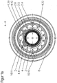
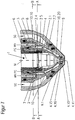
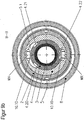
- the in the FIG. 1 shown plasma burner head 1 takes with an electrode holder 6, an electrode 7 in the present case via a thread (not shown).
- the electrode is designed as a flat electrode.
- air or oxygen can be used as the plasma gas (PG).
- a nozzle 4 is received by a substantially cylindrical nozzle holder 5.
- a nozzle cap 2 which is attached via a thread (not shown) to the plasma burner head 1, fixed the nozzle 4 and forms with this a cooling liquid space 10.
- the cooling liquid space 10 is realized by a realized with a circular ring seal 4.16, which in a groove 4.15 of Nozzle 4 is sealed between the nozzle 4 and the nozzle cap 2.
- a cooling liquid eg. As water or antifreeze added water flows through the coolant chamber 10 from a bore of the coolant flow WV to a bore of the coolant return WR, wherein the holes are arranged offset by 180 ° to each other.
- the nozzle bore 4.10 of the nozzle 4 is insufficiently cooled because the cooling liquid insufficiently flows through the part 10.20 of the cooling liquid space 10 closest to the nozzle bore and / or even on the side facing the coolant liquid return not reached.
- the cooling liquid is aptly directed into the cooling liquid space 10 almost perpendicular to the longitudinal axis of the plasma burner head 1 from the nozzle holder 5 to the nozzle 4.
- a deflection space 10.10 of the cooling liquid space 10 the cooling liquid from the direction parallel to the longitudinal axis in the bore of the cooling liquid flow WV of the plasma burner in Direction first nozzle section 4.1 (s. Fig. 2 ) is deflected almost perpendicular to the longitudinal axis of the plasma burner head 1.
- the cooling liquid flows through the coolant flowing from adestattkeitsvorlaufnut 4.20 (s. Fig. 1a .
- the plasma burner head 1 is equipped with a nozzle protection cap holder 8 and a nozzle protection cap 9. Through this area flows the secondary gas SG, in the plasma jet surrounds.
- the secondary gas SG flows through a secondary gas guide 9.1 and can be rotated by this.
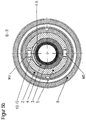
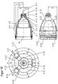
- Fig. 1a shows a sectional view along the line AA of the plasma torch FIG. 1 , This shows how the formed by thedefactkeitszulaufnut 4.20 of the nozzle 4 and the nozzle cap 2 space 10.11 by sections 4.41 and 4.42 of protruding portions 4.31 and 4.32 of the nozzle 4 in combination with the inner surface 2.5 of the nozzle cap 2 prevent a shunt between the cooling liquid flow and coolant return , So that in each position of the nozzle 4 to the nozzle cap 2 to each other, the shunt of the cooling liquid is prevented, the sheet dimensions d4 and e4 of sections 4.41 and 4.42 of the protruding areas 4.31 and 4.32 of the nozzle 4 must be at least as large as the radians b2 to the nozzle facing recesses 2.6 of the nozzle cap 2 (s. Fig. 14 to 16 ).
- an effective cooling of the nozzle 4 is achieved in the region of the nozzle tip and prevents thermal overload. It is ensured that as much coolant as possible reaches the space 10.20 of the coolant chamber 10. There was no discoloration of the nozzle in the area of the nozzle bore 4.10 in experiments. Also leaks between the nozzle 4 and the nozzle cap 2 did not occur and the circular ring 4.16 was not overheated.
- FIG. 1b includes a sectional view taken along the line B of the plasma burner head FIG. 1 , which shows the plane of the deflection 10.10.
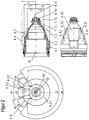
- Fig. 2 shows the nozzle 4 of the plasma burner head FIG. 1 , It has a nozzle bore 4.10 for the exit of a plasma jet at a nozzle tip 4.11, a first section 4.1, the outer surface 4.4 is substantially cylindrical, and adjoining the nozzle tip 4.11 second section 4.2, the outer surface of the 4.5 to the nozzle tip 4.11 out in essentially conically tapered.
- Thedestattkeitszulaufnut 4.20 extends over a portion of the first section 4.1 and the second section 4.2 in the outer surface 4.5 of the nozzle 4 to the nozzle tip 4.11 and ends in front of the cylindrical outer surface 4.3.
- Thedestattkeits Weglaufnut 4.22 extends over the second section 4.2 of the nozzle 4.
- the center of thedeckenkeitszulaufnut 4.20 and the center of thedefactkeitsschreiblaufnut (4.22) are arranged offset by 180 ° to each other over the circumference of the nozzle (4).
- the width alpha 4 of thedefactkeitsschreiblaufnut 4.22 in the circumferential direction is about 250 °.
- Between thedeckenkeitsvorlaufnut 4.20 and thedeckenkeitsschreiblaufnut 4.22 are the outwardly projecting areas 4.31 and 4.32 with the corresponding sections 4.41 and 4.42.
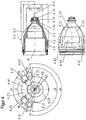
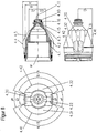
- FIG. 3 shows a plasma burner similar FIG. 1 ,
- the nozzle 4 has twodestattkeitszulaufnuten 4.20 and 4.21.
- the cooling liquid is directed almost perpendicular to the longitudinal axis of the plasma burner head 1 of the nozzle holder 5 on the nozzle 4 in the cooling liquid space 10.
- the cooling liquid is deflected from the direction parallel to the longitudinal axis in the bore of the cooling liquid flow WV of the plasma burner in the direction of the first nozzle section 4.1 almost perpendicular to the longitudinal axis of the plasma burner head 1.
- the cooling liquid flows through a groove 5.1 of the nozzle holder 5 in the two formed by thedeckenkeitszulaufnuten 4.20 and 4.21 of the nozzle 4 and the nozzle cap 2 spaces 10.11 and 10.12 to the nozzle bore 4.10 surrounding area 10.20 of the cooling liquid space 10 and flows around the nozzle 4 there , Thereafter, the cooling liquid flows back through the space 10.15 formed by the cooling liquid return groove 4.22 of the nozzle 4 and the nozzle cap 2 to the coolant return WR, the transition taking place substantially parallel to the longitudinal axis of the plasma burner head.
- Fig. 3a includes a sectional view taken along the line AA of the plasma torch FIG. 3 and shows how the spaces 10.11 and 10.12 formed by the cooling liquid supply grooves 4.20 and 4.21 of the nozzle 4 and the nozzle cap 2 form a shunt between the portions 4.41 and 4.42 of the protruding portions 4.31 and 4.32 of the nozzle 4 in combination with the inner surface 2.5 of the nozzle cap 2 Prevent the coolant flow and coolant return. At the same time, a shunt between the spaces 10.11 and 10.12 is prevented by the section 4.43 of the protruding area 4.33.
- the sheet dimensions d4 and e4 of sections 4.41 and 4.42 of the nozzle 4 must be at least as large as the radians b2 to the nozzle facing recesses 2.6 of the nozzle cap 2 (s , Fig. 14 to 16 ).
- FIG. 3b is a sectional view taken along the line BB of the plasma torch FIG. 3 that the plane of the deflection 10.10 and the connection with both coolant outlets 4.20 and 4.21 through the groove 5.1 in the nozzle holder 5 shows.
- Fig. 4 shows the nozzle 4 of the plasma burner head FIG. 3 , It has a nozzle bore 4.10 for the exit of a plasma jet at a nozzle tip 4.11, a first section 4.1, the outer surface 4.4 is substantially cylindrical, and adjoining the nozzle tip 4.11 second section 4.2, the outer surface of the 4.5 to the nozzle tip 4.11 out in essentially conically tapered.
- Thedestattkeitszulaufnuten 4.20 and 4.21 extend over a portion of the first section 4.1 and the second section 4.2 in the outer surface of the nozzle 4 4.5 to the nozzle tip 4.11 and end in front of the cylindrical outer surface 4.3.
- Thedestattkeits Weglaufnut 4.22 extends over the second section 4.2 of the nozzle 4.
- the width alpha 4 of thede crampkeitsschreiblaufnut 4.22 in the circumferential direction is about 190 °.
- Between thedeckenkeitszulaufnuten 4.20; 4.21 and thedeckenkeitsschreiblaufnut 4.22 are the outwardly projecting areas 4.31; 4.32 and 4.33 with the corresponding sections 4.41; 4.42 and 4.43.
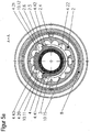
- FIG. 5 shows a plasma burner similar FIG. 3 but according to a particular embodiment of the invention.
- the nozzle 4 has twodestattkeitszulaufnuten 4.20 and 4.21 (s. Fig. 5a ).
- the cooling liquid is directed almost perpendicular to the longitudinal axis of the plasma burner head 1 of the nozzle holder 5 on the nozzle 4 in the cooling liquid space 10.
- the cooling liquid is deflected from the direction parallel to the longitudinal axis in the bore of the cooling liquid flow WV of the plasma burner in the direction of the first nozzle section 4.1 almost perpendicular to the longitudinal axis of the plasma burner head 1.
- the cooling liquid flows through a remplisstechnikszulaufnut 4.6 of the nozzle 4 in the two formed by thedefactkeitsvorlaufnuten 4.20 and 4.21 of the nozzle 4 and the nozzle cap 2 spaces 10.11 and 10.12 to the nozzle bore 4.10 surrounding area 10.20 of the cooling liquid chamber 10 and flows around the nozzle 4 there , Thereafter, the cooling liquid flows back through the space 10.15 formed by the cooling liquid return groove 4.22 of the nozzle 4 and the nozzle cap 2 to the coolant return WR, the transition taking place substantially parallel to the longitudinal axis of the plasma burner head.
- Fig. 5a is the sectional view taken along the line AA of the plasma torch FIG. 5 showing how the spaces 10.11 and 10.12 formed by the cooling liquid supply grooves 4.20 and 4.21 of the nozzle 4 and the nozzle cap 2 form a shunt through the sections 4.41 and 4.42 of the protruding areas 4.31 and 4.32 of the nozzle 4 in combination with the inner surface 2.5 of the nozzle cap 2 between the coolant flow and coolant return. At the same time, a shunt between the spaces 10.11 and 10.12 is prevented by the section 4.43 of the protruding area 4.33.
- the sheet dimensions d4 and e4 of sections 4.41 and 4.42 of the nozzle 4 must be at least as large as the radians b2 to the nozzle facing recesses 2.6 of the nozzle cap. 2
- FIG. 5b is a sectional view taken along the line BB of the plasma torch FIG. 5 showing the plane of the deflection space 10.10 and the connection with both coolant liquid feeds through the liquid inlet groove 4.6 in the nozzle 4.
- Fig. 6 shows the nozzle 4 of the plasma burner head FIG. 5 , It has a nozzle bore 4.10 for the exit of a plasma jet at a nozzle tip 4.11, a first section 4.1, the outer surface 4.4 is substantially cylindrical, and adjoining the nozzle tip 4.11 second section 4.2, the outer surface of the 4.5 to the nozzle tip 4.11 out in essentially conically tapered.
- Thedestattkeitszulaufnuten 4.20 and 4.21 extend over a portion of the first section 4.1 and the second section 4.2 in the outer surface of the nozzle 4 4.5 to the nozzle tip 4.11 and end in front of the cylindrical outer surface 4.3.
- Thedestattkeits Weglaufnut 4.22 extends over the second section 4.2 of the nozzle 4.
- the width alpha 4 of thede crampkeitsschreiblaufnut 4.22 in the circumferential direction is about 190 °.
- the cooling liquid grooves 4.20; 4.21 and thedeckenkeitsschreiblaufnut 4.22 are the outwardly projecting areas 4.31; 4.32 and 4.33 with the corresponding sections 4.41; 4.42 and 4.43.
- Thedestattkeitszulaufnuten 4.20 and 4.21 are interconnected by the groove 4.6 of the nozzle.
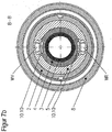
- FIG. 7 illustrates a plasma burner head according to another specific embodiment, the embodiment not belonging to the invention.
- the cooling liquid is directed almost perpendicular to the longitudinal axis of the plasma burner head 1 of a nozzle holder 5 on the nozzle 4 in a cooling liquid space 10.
- the cooling liquid is deflected from the direction parallel to the longitudinal axis in the bore of the cooling liquid flow WV of the plasma burner in the direction of the first nozzle section 4.1 almost perpendicular to the longitudinal axis of the plasma burner head 1.
- the cooling liquid flows through a space 10.11 formed by a cooling liquid supply groove 4.20 of the nozzle 4 and the nozzle cap 2 (see FIG. Fig.
- Fig. 7a is a sectional view taken along the line AA of the plasma torch FIG. 7 showing how the space 10.11 formed by the coolant inlet groove 4.20 of the nozzle 4 and the nozzle cap 2 passes through the portions 4.41 and 4.42 of the protruding areas 4.31 and 4.32 of the nozzle 4 in combination with the inner surface of the nozzle cap 2 to prevent a shunt between the cooling liquid flow and coolant return.
- FIG. 7b is a sectional view taken along the line BB of the plasma burner head FIG. 7 showing the plane of the deflection spaces 10.10.
- Fig. 8 shows the nozzle 4 of the plasma burner head FIG. 7 , It has a nozzle bore 4.10 for the exit of a plasma jet at a nozzle tip 4.11, a first section 4.1, the outer surface 4.4 is substantially cylindrical, and adjoining the nozzle tip 4.11 second section 4.2, the outer surface of the 4.5 to the nozzle tip 4.11 out in essentially conically tapered.
- Thedefactkeitszulaufnut 4.20 and thedeckenkeitsschreibonnenut 4.22 extend over a portion of the first section 4.1 and the second section 4.2 in the outer surface 4.5 of the nozzle 4 to the nozzle tip 4.11 and end in front of the cylindrical outer surface 4.3.
- the center of thedeckenkeitszulaufnut 4.20 and the center of thedeckensschreiblaufnut 4.22 are offset by 180 ° to each other over the circumference of the nozzle 4 and the same size. Between thedeckenkeitsvorlaufnut 4.20 and thedeckensschreiblaufnut 4.22 are the outwardly projecting areas 4.31 and 4.32 with the corresponding sections 4.41 and 4.42.
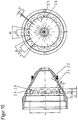
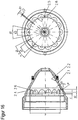
- FIG. 9 shows a plasma burner head, the embodiment does not belong to the invention.
- the nozzle 4 has twodestattkeitsvorlaufnuten 4.20 and 4.21.
- the cooling liquid is directed almost perpendicular to the longitudinal axis of the plasma burner head 1 of the nozzle holder 5 on the nozzle 4 in the cooling liquid space 10.
- the cooling liquid is deflected from the direction parallel to the longitudinal axis in the bore of the cooling liquid flow WV of the plasma torch in the direction of the first nozzle section 4.1 almost perpendicular to the longitudinal axis of the plasma burner head 1.
- the cooling liquid flows through a groove 5.1 of the nozzle holder 5 in the two formed by thedeckenkeitszulaufnuten 4.20 and 4.21 of the nozzle 4 and the nozzle cap 2 spaces 10.11 and 10.12 to the nozzle bore 4.10 surrounding area 10.20 of the cooling liquid space 10 and flows around the nozzle 4 there , Thereafter, the cooling liquid flows back through the space formed by thedestattkeitsschreiblaufnut 4.22 of the nozzle 4 and the nozzle cap 2 10.15 back to the coolant return WR, the transition here is almost perpendicular to the longitudinal axis of the plasma burner head, by a deflection 10.10.
- Fig. 9a is a sectional view taken along the line AA of the plasma torch FIG. 9 showing how the spaces 10.11 and 10.12 formed by the cooling liquid inlet grooves 4.20 and 4.21 of the nozzle 4 and the nozzle cap 2 pass through the sections 4.41 and 4.42 of the protruding areas 4.31 and 4.32 of the nozzle 4 in combination with the inner surface of the nozzle cap 2 Prevent the coolant flow and coolant return. At the same time, a shunt between the spaces 10.11 and 10.12 is prevented by the section 4.43 of the protruding area 4.33.
- FIG. 9b is a sectional view taken along the line BB of the plasma burner head FIG. 9 showing the plane of the deflection spaces 10.10 and shows the connection with bothdestattkeitsvor conceptn 4.20 and 4.21 through the groove 5.1 in the nozzle holder 5.
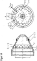
- FIG. 10 shows the nozzle 4 of the plasma burner head FIG. 9 , It has a nozzle bore 4.10 for the exit of a plasma jet at a nozzle tip 4.11, a first section 4.1, the outer surface 4.4 is substantially cylindrical, and adjoining the nozzle tip 4.11 second section 4.2, the outer surface of the 4.5 to the nozzle tip 4.11 out in essentially conically tapered.
- Thedestattkeitszulaufnuten 4.20 and 4.21 extend over a portion of the first section 4.1 and the second section 4.2 in the outer surface of the nozzle 4 4.5 to the nozzle tip 4.11 back and end in front of the cylindrical outer surface 4.3.
- Thedeckenkeitsschreiblaufnut 4.22 extends over the second section 4.2 and the first section 4.1 in the outer surface 4.5 of the nozzle 4. Between thedeckenkeitsvorlaufnuten 4.20; 4.21 and thedeckensschreiblaufnut 4.22 are the outwardly projecting areas 4.31; 4.32 and 4.33 with the corresponding sections 4.41; 4.42 and 4.43.
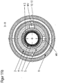
- FIG. 11 shows a plasma burner head similar FIG. 5 but according to another particular embodiment of the invention.
- the bores of the coolant flow WV and the coolant return are arranged at an angle of 90 °.
- the nozzle 4 has twodestattkeitszulaufnuten 4.20 and 4.21 and in the circumferential direction of the first section 4.1 over the entire circumference horrrekkende and thedefactkeitszulaufnuten connecting groove 4.6.
- the cooling liquid is directed approximately perpendicular to the longitudinal axis of the plasma burner head 1 of the nozzle holder 5 on the nozzle 4 aptly into the cooling liquid space 10.
- the cooling liquid is deflected from the direction parallel to the longitudinal axis in the bore of the cooling liquid flow WV of the plasma burner in the direction of the first nozzle section 4.1 almost perpendicular to the longitudinal axis of the plasma burner head 1.
- the cooling liquid flows through the sosstechnikszulaufnut 4.6, which extends in the circumferential direction of the first section 4.1 of the nozzle 4 on a partial circumference between the grooves 4.20 and 4.21, ie over about 300 °, in the two by thedefactkeitsvorlaufnuten 4.20 and 4.21 of Nozzle 4 and the nozzle cap 2 formed spaces 10.11 and 10.12 to the nozzle bore 4.10 surrounding area 10.20 of the cooling liquid space 10 and flows around the nozzle 4 there. Thereafter, the cooling liquid flows back through the space 10.15 formed by the cooling liquid return groove 4.22 of the nozzle 4 and the nozzle cap 2 to the coolant return WR, the transition taking place substantially parallel to the longitudinal axis of the plasma burner head.
- Fig. 11a is a sectional view taken along the line AA of the plasma torch FIG. 11 showing how the spaces 10.11 and 10.12 formed by the cooling liquid inlet grooves 4.20 and 4.21 of the nozzle 4 and the nozzle cap 2 form a shunt through the sections 4.41 and 4.42 of the protruding areas 4.31 and 4.32 of the nozzle 4 in combination with the inside surface 2.5 of the nozzle cap 2 between the coolant flow and coolant return. At the same time, a shunt between the spaces 10.11 and 10.12 is prevented by the section 4.43 of the protruding area 4.33.
- the sheet dimensions d4 and e4 of sections 4.41 and 4.42 of the nozzle 4 must be at least as large as the radians b2 to the nozzle facing recesses 2.6 of the nozzle cap. 2
- FIG. 11b is a sectional view taken along the line BB of the plasma torch FIG. 11 , which shows the plane of the deflection space 10.10 and the connection with both cooling liquid flows through the over approximately 300 ° circumferential liquid inlet groove 4.6 in the nozzle 4 and offset by 90 ° arranged holes for the coolant flow WV and the coolant return WR.
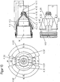
- FIG. 12 shows the nozzle 4 of the plasma burner head FIG. 11 , It has a nozzle bore 4.10 for the exit of a plasma jet at a nozzle tip 4.11, a first section 4.1, the outer surface 4.4 is substantially cylindrical, and adjoining the nozzle tip 4.11 second section 4.2, the outer surface of the 4.5 to the nozzle tip 4.11 out in essentially conically tapered.
- Thedestattkeitszulaufnuten 4.20 and 4.21 extend over a portion of the first section 4.1 and the second section 4.2 in the outer surface of the nozzle 4 4.5 to the nozzle tip 4.11 back and end in front of the cylindrical outer surface 4.3.
- Thedestattkeits Weglaufnut 4.22 extends over the second section 4.2 of the nozzle 4.
- Thedeckenkeitszulaufnuten 4.20; 4.21 and thedeckenkeitsschreiblaufnut 4.22 are the outwardly projecting areas 4.31; 4.32 and 4.33 with the corresponding sections 4.41; 4.42 and 4.43.
- Thedeckenkeitszulaufnuten 4.20 and 4.21 are connected by a circumferential direction of the first section 4.1 of the nozzle 4 on a partial circumference between the grooves 4.20 and 4.21, ie over about 300 ° extending liquid inlet groove 4.6 of the nozzle. This is particularly advantageous for the cooling of the transition between the nozzle holder 5 and the nozzle 4.
- FIG. 13 shows a nozzle according to another specific embodiment of the invention, which in the plasma burner head after FIG. 8 can be used.
- Thedestattkeitszulaufnut 4.20 is connected to a remplisstechnikszulaufnut 4.6 which extends in the circumferential direction over the entire circumference.
- This has the advantage that the bore for the cooling liquid flow WV and the coolant return WR in the plasma burner head need not be arranged offset by exactly 180 °, but also as for example in FIG. 11 can be arranged offset by 90 °.
- this is advantageous for the cooling of the transition between the nozzle holder 5 and the nozzle 4.
- the same can of course be used for achenkeits Weglaufnut 4.22.
- FIG. 14 shows a nozzle cap 2, wherein the embodiment does not belong to the invention.
- the nozzle cap 2 has an essentially conically tapering inner surface 2.2, which in this case has recesses 2.6 in a radial plane.
- the recesses 2.6 are arranged equidistantly over the inner circumference and semicircular in the radial section.
- FIGS. 15 and 16 shown nozzle caps differ from the in Fig. 14 shown embodiment in the shape of the recesses 2.6.
- the recesses 2.6 in Fig. 15 are in the view shown there to the nozzle tip out frustoconical, with in Fig. 16 the frustoconical shape is slightly rounded.
Claims (15)
- Buse (4) pour une torche à plasma refroidie par liquide, comportant un alésage de buse (4,10) pour la sortie d'un jet de plasma à un sommet de buse (4.11), une première section (4.1), dont la surface extérieure (4.4) est sensiblement cylindrique, et une deuxième section (4.2) s'étendant de la première section jusqu'au sommet de buse (4.11), dont la surface extérieure (4.5) se rétrécit sensiblement en forme de cône vers le sommet de buse (4.11), où a) il est prévu au moins une rainure d'amenée de liquide (4.20 ; 4.21) qui s'étend sur la deuxième section (4.2) vers le sommet de buse (4.11) à la surface extérieure (4.5) de la buse (4) et il est prévu une seule rainure de retour de liquide (4.22) séparée de la, ou des rainures d'amenée de liquide (4.20 ; 4.21) et qui s'étend sur la deuxième section (4.2), ou bien b) il est prévu une seule rainure d'amenée de liquide (4.20 ou 4.21) qui s'étend sur la deuxième section (4.2) vers le sommet de buse (4.11) à la surface extérieure (4.5) de la buse (4) et il est prévu au moins une rainure de retour de liquide (4.22) séparée de la rainure d'amenée de liquide (4.20 ou 4.21) qui s'étend sur la deuxième section (4.2), la rainure d'amenée de liquide (4.20 ; 4.21) s'étendant également sur une partie de la première section (4.1), caractérisée en ce qu'une rainure d'amenée de liquide (4.6) reliée à la rainure d'amenée de liquide (4.20) et qui s'étend dans la direction périphérique de la première section (4.1) se trouve dans la première section (4.1) de la buse (4) dans le cas a), et en ce qu'une rainure de retour de liquide reliée à la rainure de retour de liquide (4.22) et qui s'étend dans la direction périphérique de la première section (4.1) se trouve dans la première section (4.1) de la buse (4) dans le cas b).
- Buse selon la revendication 1, caractérisée en ce que la ou les rainures de retour de liquide (4.22) s'étendent également sur une partie de la première section (4.1) à la surface extérieure de la buse (4).
- Buse selon la revendication 1 ou 2, caractérisée en ce qu'au moins deux rainures d'amenée de liquide (4.20 ; 4.21) sont prévues dans le cas a), et au moins deux rainures de retour de liquide (4.22) dans le cas b).
- Buse selon la revendication 3, caractérisée en ce que le point central de la rainure d'amenée de liquide (4.20) et le point central de la rainure de retour de liquide (4.22) sont décalés de 180° l'un par rapport à l'autre sur la périphérie de la buse (4).
- Buse selon l'une des revendications 1 à 4, caractérisée en ce que la largeur de la rainure de retour de liquide dans le cas a) et la largeur de la rainure d'amenée de liquide dans le cas b) est comprise entre 90° et 270° dans la direction périphérique.
- Buse selon l'une des revendications précédentes, caractérisée en ce que la rainure d'amenée de liquide (4.6) s'étend sur toute la périphérie dans la direction périphérique de la première section (4.1) de la buse (4) dans le cas a), ou en ce que la rainure d'amenée de liquide (4.6) s'étend sur un angle compris entre 60° et 300° dans la direction périphérique de la première section (4.1) de la buse (4) dans le cas a), et en ce que la rainure de retour de liquide s'étend sur un angle compris entre 60° et 300° dans la direction périphérique de la première section (4.1) de la buse (4) dans le cas b), ou en ce que la rainure d'amenée de liquide (4.6) s'étend sur un angle compris entre 90° et 270° dans la direction périphérique de la première section (4.1) de la buse (4) dans le cas a), et en ce que la rainure de retour de liquide s'étend sur un angle compris entre 90° et 270° dans la direction périphérique de la première section (4.1) de la buse (4) dans le cas b).
- Buse selon l'une des revendications précédentes, caractérisée en ce que seulement deux rainures d'amenée de liquide (4.20 ; 4.21) sont prévues dans le cas a), et seulement deux rainures de retour de liquide (4.22) dans le cas b).
- Buse selon la revendication 7, caractérisée en ce que les deux rainures d'amenée de liquide (4.20 ; 4.21) sont disposées sur la périphérie de la buse symétriquement à une droite qui traverse à angle droit l'axe longitudinal de la buse (4) depuis le point central de la rainure de retour de liquide (4.22) dans le cas a), et les deux rainures de retour de liquide sont disposées sur la périphérie de la buse symétriquement à une droite qui traverse à angle droit l'axe longitudinal de la buse (4) depuis le point central de la rainure d'amenée de liquide dans le cas b).
- Buse selon la revendication 7 ou 8, caractérisée en ce que les points centraux des deux rainures d'amenée de liquide (4.20 ; 4.21) dans le cas a) et les points centraux des deux rainures de retour de liquide dans le cas b) sont décalés l'un par rapport à l'autre d'un angle compris entre 30° et 180° sur la périphérie de la buse (4).
- Buse selon l'une des revendications 7 à 9, caractérisée en ce que la largeur de la rainure de retour de liquide (4.22) dans le cas a) et la largeur de la rainure d'amenée de liquide dans le cas b) est comprise entre 120° et 270° dans la direction périphérique.
- Buse selon l'une des revendications 7 à 10, caractérisée en ce que les deux rainures d'amenée de liquide (4.20 ; 4.21) sont reliées l'une à l'autre dans la première section (4.1) de la buse (4) dans le cas a), et en ce que les deux rainures de retour de liquide sont reliées l'une à l'autre dans la première section (4.1) de la buse (4) dans le cas b).
- Buse selon la revendication 11, caractérisée en ce que les deux rainures d'amenée de liquide (4.20 ; 4.21) sont reliées l'une à l'autre par une rainure d'amenée de liquide (4.6) dans la première section (4.1) de la buse (4) dans le cas a), et en ce que les deux rainures de retour de liquide sont reliées l'une à l'autre par une rainure de retour de liquide dans la première section (4.1) de la buse (4) dans le cas b), en particulier en ce que la rainure d'amenée de liquide (4.6) dépasse d'une ou des deux rainures d'amenée de liquide (4.20 ; 4.21) dans le cas a) et en ce que la rainure de retour de liquide dépasse d'une ou des deux rainures de retour de liquide dans le cas b).
- Tête de torche à plasma (1), comportant :- une buse selon l'une des revendications 1 à 12,- un support de buse (5) pour le maintien de la buse (4), et- un capuchon de buse (2), de préférence ledit capuchon de buse (2) présentant une surface intérieure (2.2) qui se rétrécit sensiblement en forme de cône et une surface extérieure qui se rétrécit sensiblement en forme de cône, en outre la surface intérieure (2.2) du capuchon de buse (2) présentant au moins deux, en particulier exactement trois évidements (2.6) sur un plan radial qui se trouve dans la région de la surface extérieure se rétrécissant sensiblement en forme de cône, ledit capuchon de buse (2) et la buse (4) formant un compartiment (10) à liquide de refroidissement pouvant être relié par deux alésages décalés respectivement de 60° à 180° à une conduite d'amenée de liquide de refroidissement ou à une conduite de retour de liquide de refroidissement, le support de buse (5) étant réalisé de telle manière que le liquide de refroidissement parvienne dans le compartiment (10) à liquide de refroidissement pratiquement perpendiculairement à l'axe longitudinal de la tête de torche à plasma (1) incident à la buse (4) et/ou parvienne dans le support de buse pratiquement perpendiculairement à l'axe longitudinal depuis le compartiment à liquide de refroidissement.
- Tête de torche à plasma (1) selon la revendication 13, caractérisée en ce que la buse (4) présente une ou deux rainures d'amenée de liquide de refroidissement (4.20 ; 4.21), et le capuchon de buse (2) sur sa surface intérieure (2.5) au moins deux, en particulier exactement trois, évidements (2.6), dont les orifices ouverts vers la buse (4) s'étendent respectivement sur une mesure d'arc (b2), la mesure d'arc (d4 ; e4) de chacune des zones (4.31 ; 4.32) de la buse (4) adjacentes aux rainures d'amenée de liquide de refroidissement (4.20 ; 4.21) dans la direction périphérique et dépassant vers l'extérieur par rapport à la ou aux rainures d'amenée de liquide de refroidissement, étant au moins aussi grande que la mesure d'arc (b2).
- Tête de torche à plasma (1) selon la revendication 13 ou 15, caractérisée en ce que la mesure d'arc (c2) de la section entre les évidements (2.6) du capuchon de buse (2) équivaut au plus à la moitié de la mesure d'arc (a4) minimale de la rainure de retour de liquide de refroidissement (4.22) ou de la mesure d'arc (b4) minimale de la rainure d'amenée de liquide de refroidissement (4.20) et/ou (4.21) de la buse (4).
Priority Applications (5)
| Application Number | Priority Date | Filing Date | Title |
|---|---|---|---|
| EP12006772.3A EP2563100B1 (fr) | 2008-10-09 | 2009-09-03 | Buse pour une torche à plasma refroidie par liquide et tête de torche à plasma dotée de celle-ci |
| SI200930633T SI2175702T1 (sl) | 2008-10-09 | 2009-09-03 | Šoba in pokrov šobe za plazemski gorilnik s hlajenjem s tekočino in glava plazemskega gorilnika z le-to/le-tema |
| PL09011322T PL2175702T5 (pl) | 2008-10-09 | 2009-09-03 | Dysza oraz nasadka na dyszę do palnika plazmowego chłodzonego cieczą, oraz głowica palnika plazmowego zawierająca jedną z nich lub obie |
| SI200930633A SI2175702T2 (sl) | 2008-10-09 | 2009-09-03 | Šoba in pokrov šobe za plazemski gorilnik s hlajenjem s tekočino in glava plazemskega gorilnika z le-to/le-tema |
| HRP20130559TT HRP20130559T4 (hr) | 2008-10-09 | 2013-06-18 | Mlaznica i poklopac mlaznice tekućinom hlađenog plazmatskog plamenika, te glava plazmatskog plamenika koja nosi jedno od njih ili oboje |
Applications Claiming Priority (2)
| Application Number | Priority Date | Filing Date | Title |
|---|---|---|---|
| DE102008050770 | 2008-10-09 | ||
| DE102009006132.0A DE102009006132C5 (de) | 2008-10-09 | 2009-01-26 | Düse für einen flüssigkeitsgekühlten Plasmabrenner, Düsenkappe für einen flüssigkeitsgekühlten Plasmabrenner sowie Plasmabrennerkopf mit derselben/denselben |
Related Child Applications (2)
| Application Number | Title | Priority Date | Filing Date |
|---|---|---|---|
| EP12006772.3A Division-Into EP2563100B1 (fr) | 2008-10-09 | 2009-09-03 | Buse pour une torche à plasma refroidie par liquide et tête de torche à plasma dotée de celle-ci |
| EP12006772.3 Division-Into | 2012-09-28 |
Publications (4)
| Publication Number | Publication Date |
|---|---|
| EP2175702A1 EP2175702A1 (fr) | 2010-04-14 |
| EP2175702B1 EP2175702B1 (fr) | 2013-03-20 |
| EP2175702B2 true EP2175702B2 (fr) | 2017-01-04 |
| EP2175702B9 EP2175702B9 (fr) | 2017-05-17 |
Family
ID=41351591
Family Applications (2)
| Application Number | Title | Priority Date | Filing Date |
|---|---|---|---|
| EP12006772.3A Withdrawn - After Issue EP2563100B1 (fr) | 2008-10-09 | 2009-09-03 | Buse pour une torche à plasma refroidie par liquide et tête de torche à plasma dotée de celle-ci |
| EP09011322.6A Active EP2175702B9 (fr) | 2008-10-09 | 2009-09-03 | Buse pour une torche à plasma refroidie par liquide, coiffe de tuyère pour une torche à plasma et tête de torche à plasma dotée de celle-ci |
Family Applications Before (1)
| Application Number | Title | Priority Date | Filing Date |
|---|---|---|---|
| EP12006772.3A Withdrawn - After Issue EP2563100B1 (fr) | 2008-10-09 | 2009-09-03 | Buse pour une torche à plasma refroidie par liquide et tête de torche à plasma dotée de celle-ci |
Country Status (17)
| Country | Link |
|---|---|
| US (1) | US8941026B2 (fr) |
| EP (2) | EP2563100B1 (fr) |
| KR (2) | KR101225435B1 (fr) |
| CN (1) | CN101836509B (fr) |
| BR (1) | BRPI0920511B1 (fr) |
| CA (1) | CA2734986C (fr) |
| DE (1) | DE102009006132C5 (fr) |
| DK (1) | DK2175702T4 (fr) |
| ES (1) | ES2425436T5 (fr) |
| HR (1) | HRP20130559T4 (fr) |
| MX (1) | MX2011002912A (fr) |
| PL (1) | PL2175702T5 (fr) |
| PT (1) | PT2175702E (fr) |
| RU (1) | RU2519245C2 (fr) |
| SI (2) | SI2175702T2 (fr) |
| WO (1) | WO2010040328A1 (fr) |
| ZA (1) | ZA201102989B (fr) |
Families Citing this family (23)
| Publication number | Priority date | Publication date | Assignee | Title |
|---|---|---|---|---|
| WO2011000337A1 (fr) | 2009-07-03 | 2011-01-06 | Kjellberg Finsterwalde Plasma Und Maschinen Gmbh | Tuyère pour une torche à plasma refroidie par liquide ainsi que tête de torche à plasma munie de celle-ci |
| US9279722B2 (en) | 2012-04-30 | 2016-03-08 | Agilent Technologies, Inc. | Optical emission system including dichroic beam combiner |
| DE102012207201B3 (de) | 2012-04-30 | 2013-04-11 | Trumpf Werkzeugmaschinen Gmbh + Co. Kg | Verfahren zum laserunterstützten Plasmaschneiden oder Plasmaschweißen und Vorrichtung dafür |
| CZ25961U1 (cs) | 2013-07-26 | 2013-10-14 | Thermacut, S.R.O. | Hlavice plazmového horáku |
| CN103447675B (zh) * | 2013-08-13 | 2016-08-10 | 杨勇 | 等离子切割机的冷却结构 |
| US11432393B2 (en) | 2013-11-13 | 2022-08-30 | Hypertherm, Inc. | Cost effective cartridge for a plasma arc torch |
| US11278983B2 (en) | 2013-11-13 | 2022-03-22 | Hypertherm, Inc. | Consumable cartridge for a plasma arc cutting system |
| US9981335B2 (en) | 2013-11-13 | 2018-05-29 | Hypertherm, Inc. | Consumable cartridge for a plasma arc cutting system |
| US10456855B2 (en) | 2013-11-13 | 2019-10-29 | Hypertherm, Inc. | Consumable cartridge for a plasma arc cutting system |
| US11684995B2 (en) | 2013-11-13 | 2023-06-27 | Hypertherm, Inc. | Cost effective cartridge for a plasma arc torch |
| DE102014205343A1 (de) | 2014-03-21 | 2015-09-24 | Siemens Aktiengesellschaft | Kühlvorrichtung für eine Spritzdüse bzw. Spritzdüsenanordnung mit einer Kühlvorrichtung für das thermische Spritzen |
| EP2942144A1 (fr) * | 2014-05-07 | 2015-11-11 | Kjellberg-Stiftung | Système de brûleur pour découpage au jet plasma et utilisation de pièces d'usure pour un système de brûleur pour découpage au jet de plasma |
| EP3180151B1 (fr) | 2014-08-12 | 2021-11-03 | Hypertherm, Inc. | Cartouche rentable pour chalumeau à arc de plasma |
| US9833859B2 (en) * | 2014-09-15 | 2017-12-05 | Lincoln Global, Inc. | Electric arc torch with cooling conduit |
| DE102015101532A1 (de) * | 2015-02-03 | 2016-08-04 | Kjellberg Stiftung | Düse für Plasmalichtbogenbrenner |
| EP3716736A1 (fr) | 2015-06-08 | 2020-09-30 | Hypertherm, Inc | Refroidissement de buses pour chalumeau à plasma et systèmes associés |
| JP7073251B2 (ja) | 2015-08-04 | 2022-05-23 | ハイパーサーム インコーポレイテッド | 液冷プラズマアークトーチ用カートリッジフレーム |
| EP3332615B1 (fr) | 2015-08-04 | 2022-04-13 | Hypertherm, Inc. | Systèmes de découpe à l'arc au plasma améliorés, consommables et procédés de fonctionnement |
| US10413991B2 (en) | 2015-12-29 | 2019-09-17 | Hypertherm, Inc. | Supplying pressurized gas to plasma arc torch consumables and related systems and methods |
| EP4294133A3 (fr) * | 2016-04-11 | 2024-03-27 | Hypertherm, Inc. | Système de coupe à arc plasma, comprenant des buses et d'autres consommables, et procédés de fonctionnement associés |
| KR20180000059U (ko) | 2016-06-27 | 2018-01-04 | 곽현만 | 플라즈마 토치용 노즐 |
| GB2568106B (en) * | 2017-11-07 | 2022-09-21 | Tetronics Tech Limited | Plasma Torch Assembly |
| EP4088554A2 (fr) * | 2020-01-09 | 2022-11-16 | Hypertherm, INC. | Buses de chalumeau de coupe à arc de plasma refroidi par liquide avec passages indépendants de la synchronisation |
Citations (3)
| Publication number | Priority date | Publication date | Assignee | Title |
|---|---|---|---|---|
| GB1416783A (en) † | 1972-02-09 | 1975-12-10 | Vysoka Skola Banska Ostrava | Plasma torches |
| DE2651185A1 (de) † | 1976-11-10 | 1978-05-11 | Nuc Weld Gmbh | Kuehleinrichtung bei einem plasmabrenner |
| EP0585977A1 (fr) † | 1989-08-17 | 1994-03-09 | Hypertherm, Inc. | Appareil de coupage au jet de plasma muni d'un écran pour le diffuseur et d'un régulateur de flux améliorés |
Family Cites Families (24)
| Publication number | Priority date | Publication date | Assignee | Title |
|---|---|---|---|---|
| DE36014C (de) | Dr. A. SCHEIDEL in Mailand | Darstellung von Orthonitroamidoparamethoxylbenzol und Orthonitroamidoparaäthoxylbenzol durch Einwirkung von Ammoniak auf Mononitrodimethylhydrochinon oder Mononitrodiäfhylhydrochinon | ||
| DD36014A1 (de) * | 1964-05-19 | 1965-02-05 | Düse für Plasmabrenner | |
| DE1565638A1 (de) * | 1967-06-12 | 1970-04-16 | Kjellberg Elektroden & Maschin | Plasmabrenner |
| DD83890A1 (de) * | 1970-05-27 | 1971-08-12 | Kühlmediumführung für Brenner | |
| DE2525939A1 (de) * | 1975-06-11 | 1976-12-23 | Messer Griesheim Gmbh | Plasmalichtbogenbrenner |
| US5396043A (en) * | 1988-06-07 | 1995-03-07 | Hypertherm, Inc. | Plasma arc cutting process and apparatus using an oxygen-rich gas shield |
| US4954688A (en) * | 1989-11-01 | 1990-09-04 | Esab Welding Products, Inc. | Plasma arc cutting torch having extended lower nozzle member |
| US5008511C1 (en) * | 1990-06-26 | 2001-03-20 | Univ British Columbia | Plasma torch with axial reactant feed |
| DE4022112C2 (de) * | 1990-07-11 | 1996-03-14 | Mannesmann Ag | Plasmabrenner für übertragenen Lichtbogen |
| DE4030541C2 (de) * | 1990-09-27 | 1997-10-02 | Dilthey Ulrich Prof Dr Ing | Brenner zur Beschichtung von Grundwerkstoffen mit pulverförmigen Zusatzwerkstoffen |
| EP1324644B1 (fr) | 1991-04-12 | 2008-07-30 | Hypertherm, Inc. | Dispositif de coupage par plasma d'arc |
| JPH08294779A (ja) * | 1995-04-21 | 1996-11-12 | Koike Sanso Kogyo Co Ltd | プラズマトーチのノズル |
| US5660743A (en) * | 1995-06-05 | 1997-08-26 | The Esab Group, Inc. | Plasma arc torch having water injection nozzle assembly |
| US5893985A (en) * | 1997-03-14 | 1999-04-13 | The Lincoln Electric Company | Plasma arc torch |
| DE19828633B4 (de) * | 1998-06-26 | 2004-07-29 | Wirth, Aloisia | Lichtbogenschweiß- oder -schneidbrenner sowie Kühlsystem, Plasmadüsen bzw. WIG-Elektrodenspannzangen, Spannsystem für Plasmaelektrodennadeln u. verfahrensübergreifendes Konstruktionsprinzip hierfür |
| JP2002086274A (ja) | 2000-09-12 | 2002-03-26 | Koike Sanso Kogyo Co Ltd | プラズマトーチ用のノズル |
| JP2005118816A (ja) | 2003-10-16 | 2005-05-12 | Koike Sanso Kogyo Co Ltd | プラズマトーチ用のノズル |
| CN2807699Y (zh) * | 2005-07-06 | 2006-08-16 | 张旭 | 大电流等离子焊枪 |
| EP1765044A1 (fr) * | 2005-09-16 | 2007-03-21 | Max-Planck-Gesellschaft zur Förderung der Wissenschaften e.V. | Source plasma |
| DE102007005316B4 (de) * | 2006-08-16 | 2009-12-03 | Kjellberg Finsterwalde Plasma Und Maschinen Gmbh | Verbindung zwischen einem Plasmabrennerverschleißteil und einer Plasmabrennerverschleißteilhalterung, Plasmabrennerverschleißteil und Plasmabrennerverschleißteilhalterung |
| US8981253B2 (en) * | 2006-09-13 | 2015-03-17 | Hypertherm, Inc. | Forward flow, high access consumables for a plasma arc cutting torch |
| JP5118404B2 (ja) * | 2006-10-18 | 2013-01-16 | コマツ産機株式会社 | プラズマ切断装置およびプラズマトーチの冷却方法 |
| US8772667B2 (en) * | 2007-02-09 | 2014-07-08 | Hypertherm, Inc. | Plasma arch torch cutting component with optimized water cooling |
| US8389887B2 (en) * | 2008-03-12 | 2013-03-05 | Hypertherm, Inc. | Apparatus and method for a liquid cooled shield for improved piercing performance |
-
2009
- 2009-01-26 DE DE102009006132.0A patent/DE102009006132C5/de not_active Expired - Fee Related
- 2009-08-14 CA CA2734986A patent/CA2734986C/fr active Active
- 2009-08-14 CN CN2009801007787A patent/CN101836509B/zh active Active
- 2009-08-14 US US13/123,592 patent/US8941026B2/en active Active
- 2009-08-14 MX MX2011002912A patent/MX2011002912A/es active IP Right Grant
- 2009-08-14 WO PCT/DE2009/001169 patent/WO2010040328A1/fr active Application Filing
- 2009-08-14 KR KR1020127025842A patent/KR101225435B1/ko active IP Right Grant
- 2009-08-14 RU RU2011117304/07A patent/RU2519245C2/ru active
- 2009-08-14 BR BRPI0920511-0A patent/BRPI0920511B1/pt active IP Right Grant
- 2009-08-14 KR KR1020117007954A patent/KR101234874B1/ko active IP Right Grant
- 2009-09-03 ES ES09011322.6T patent/ES2425436T5/es active Active
- 2009-09-03 EP EP12006772.3A patent/EP2563100B1/fr not_active Withdrawn - After Issue
- 2009-09-03 DK DK09011322.6T patent/DK2175702T4/en active
- 2009-09-03 PT PT90113226T patent/PT2175702E/pt unknown
- 2009-09-03 EP EP09011322.6A patent/EP2175702B9/fr active Active
- 2009-09-03 PL PL09011322T patent/PL2175702T5/pl unknown
- 2009-09-03 SI SI200930633A patent/SI2175702T2/sl unknown
- 2009-09-03 SI SI200930633T patent/SI2175702T1/sl unknown
-
2011
- 2011-04-20 ZA ZA2011/02989A patent/ZA201102989B/en unknown
-
2013
- 2013-06-18 HR HRP20130559TT patent/HRP20130559T4/hr unknown
Patent Citations (3)
| Publication number | Priority date | Publication date | Assignee | Title |
|---|---|---|---|---|
| GB1416783A (en) † | 1972-02-09 | 1975-12-10 | Vysoka Skola Banska Ostrava | Plasma torches |
| DE2651185A1 (de) † | 1976-11-10 | 1978-05-11 | Nuc Weld Gmbh | Kuehleinrichtung bei einem plasmabrenner |
| EP0585977A1 (fr) † | 1989-08-17 | 1994-03-09 | Hypertherm, Inc. | Appareil de coupage au jet de plasma muni d'un écran pour le diffuseur et d'un régulateur de flux améliorés |
Also Published As
Similar Documents
| Publication | Publication Date | Title |
|---|---|---|
| EP2175702B2 (fr) | Buse pour une torche à plasma refroidie par liquide, coiffe de tuyère pour une torche à plasma et tête de torche à plasma dotée de celle-ci | |
| EP2449862B1 (fr) | Tuyère pour une torche à plasma refroidie par liquide ainsi que tête de torche à plasma munie de celle-ci | |
| EP2140739B1 (fr) | Buse pour torche à plasma refroidie à liquide, dispositif comprenant cette buse et un capuchon pour buse, et torche à plasma refroidie à liquide présentant ledit dispositif | |
| EP2465334B1 (fr) | Capot de protection de buse et porte-capot de protection de buse ainsi que torche à plasma équipée de l'un et/ou de l'autre | |
| EP2417840B1 (fr) | Tuyaux de refroidissement, support d'électrode et électrode pour une torche à plasma d'arc et ensemble comprenant ces éléments ainsi que torche à plasma d'arc dotée de ces éléments | |
| DE102004049445C5 (de) | Plasmabrenner | |
| EP2210455B1 (fr) | Electrode pour torche a plasma | |
| DE102011088433A1 (de) | Verfahren und Plasmalichtbogenbrennersystem zum Markieren und Schneiden von Werkstücken mit dem selben Satz an Hilfsstoffen | |
| WO2018229308A2 (fr) | Électrodes pour torches à plasma refroidies par gaz et liquide, agencement d'une électrode et d'un tube de refroidissement, guidage des gaz, torche à plasma, procédé de guidage des gaz dans une torche à plasma et procédé pour faire fonctionner une torche à plasma | |
| DE102009031857C5 (de) | Düse für einen flüssigkeitsgekühlten Plasmabrenner sowie Plasmabrennerkopf mit derselben | |
| EP2667689B1 (fr) | Électrode pour chalumeau de coupe au plasma ainsi que son utilisation | |
| EP2531320B1 (fr) | Buse pour un chalumeau de decoupe plasma, munie de rainures pour le refroidissement par liquide | |
| DE102010053721B4 (de) | Brenner für das Wolfram-Inertgas-Schweißen sowie Elektrode zur Verwendung bei einem solchen Brenner | |
| DE102009060849A1 (de) | Düse für einen flüssigkeitsgekühlten Plasmabrenner sowie Plasmabrennerkopf mit derselben | |
| DE202009012491U1 (de) | Düse für einen flüssigkeitsgekühlten Plasmabrenner sowie Plasmabrennerkopf mit derselben |
Legal Events
| Date | Code | Title | Description |
|---|---|---|---|
| PUAI | Public reference made under article 153(3) epc to a published international application that has entered the european phase |
Free format text: ORIGINAL CODE: 0009012 |
|
| AK | Designated contracting states |
Kind code of ref document: A1 Designated state(s): AT BE BG CH CY CZ DE DK EE ES FI FR GB GR HR HU IE IS IT LI LT LU LV MC MK MT NL NO PL PT RO SE SI SK SM TR |
|
| AX | Request for extension of the european patent |
Extension state: AL BA RS |
|
| 17P | Request for examination filed |
Effective date: 20100818 |
|
| 17Q | First examination report despatched |
Effective date: 20101015 |
|
| GRAP | Despatch of communication of intention to grant a patent |
Free format text: ORIGINAL CODE: EPIDOSNIGR1 |
|
| GRAS | Grant fee paid |
Free format text: ORIGINAL CODE: EPIDOSNIGR3 |
|
| GRAA | (expected) grant |
Free format text: ORIGINAL CODE: 0009210 |
|
| AK | Designated contracting states |
Kind code of ref document: B1 Designated state(s): AT BE BG CH CY CZ DE DK EE ES FI FR GB GR HR HU IE IS IT LI LT LU LV MC MK MT NL NO PL PT RO SE SI SK SM TR |
|
| REG | Reference to a national code |
Ref country code: GB Ref legal event code: FG4D Free format text: NOT ENGLISH |
|
| REG | Reference to a national code |
Ref country code: CH Ref legal event code: EP |
|
| REG | Reference to a national code |
Ref country code: IE Ref legal event code: FG4D Free format text: LANGUAGE OF EP DOCUMENT: GERMAN |
|
| REG | Reference to a national code |
Ref country code: AT Ref legal event code: REF Ref document number: 602732 Country of ref document: AT Kind code of ref document: T Effective date: 20130415 |
|
| REG | Reference to a national code |
Ref country code: DE Ref legal event code: R096 Ref document number: 502009006527 Country of ref document: DE Effective date: 20130516 |
|
| REG | Reference to a national code |
Ref country code: HR Ref legal event code: TUEP Ref document number: P20130559 Country of ref document: HR |
|
| REG | Reference to a national code |
Ref country code: DK Ref legal event code: T3 |
|
| REG | Reference to a national code |
Ref country code: PT Ref legal event code: SC4A Free format text: AVAILABILITY OF NATIONAL TRANSLATION Effective date: 20130620 |
|
| REG | Reference to a national code |
Ref country code: CH Ref legal event code: NV Representative=s name: KAMINSKI HARMANN PATENTANWAELTE EST., LI |
|
| REG | Reference to a national code |
Ref country code: SE Ref legal event code: TRGR |
|
| PG25 | Lapsed in a contracting state [announced via postgrant information from national office to epo] |
Ref country code: LT Free format text: LAPSE BECAUSE OF FAILURE TO SUBMIT A TRANSLATION OF THE DESCRIPTION OR TO PAY THE FEE WITHIN THE PRESCRIBED TIME-LIMIT Effective date: 20130320 Ref country code: BG Free format text: LAPSE BECAUSE OF FAILURE TO SUBMIT A TRANSLATION OF THE DESCRIPTION OR TO PAY THE FEE WITHIN THE PRESCRIBED TIME-LIMIT Effective date: 20130620 |
|
| REG | Reference to a national code |
Ref country code: HR Ref legal event code: T1PR Ref document number: P20130559 Country of ref document: HR |
|
| REG | Reference to a national code |
Ref country code: NO Ref legal event code: T2 Effective date: 20130320 |
|
| REG | Reference to a national code |
Ref country code: NL Ref legal event code: T3 |
|
| REG | Reference to a national code |
Ref country code: LT Ref legal event code: MG4D |
|
| PG25 | Lapsed in a contracting state [announced via postgrant information from national office to epo] |
Ref country code: LV Free format text: LAPSE BECAUSE OF FAILURE TO SUBMIT A TRANSLATION OF THE DESCRIPTION OR TO PAY THE FEE WITHIN THE PRESCRIBED TIME-LIMIT Effective date: 20130320 |
|
| REG | Reference to a national code |
Ref country code: GR Ref legal event code: EP Ref document number: 20130401203 Country of ref document: GR Effective date: 20130711 |
|
| REG | Reference to a national code |
Ref country code: ES Ref legal event code: FG2A Ref document number: 2425436 Country of ref document: ES Kind code of ref document: T3 Effective date: 20131015 |
|
| PG25 | Lapsed in a contracting state [announced via postgrant information from national office to epo] |
Ref country code: RO Free format text: LAPSE BECAUSE OF FAILURE TO SUBMIT A TRANSLATION OF THE DESCRIPTION OR TO PAY THE FEE WITHIN THE PRESCRIBED TIME-LIMIT Effective date: 20130320 Ref country code: IS Free format text: LAPSE BECAUSE OF FAILURE TO SUBMIT A TRANSLATION OF THE DESCRIPTION OR TO PAY THE FEE WITHIN THE PRESCRIBED TIME-LIMIT Effective date: 20130720 Ref country code: EE Free format text: LAPSE BECAUSE OF FAILURE TO SUBMIT A TRANSLATION OF THE DESCRIPTION OR TO PAY THE FEE WITHIN THE PRESCRIBED TIME-LIMIT Effective date: 20130320 |
|
| REG | Reference to a national code |
Ref country code: PL Ref legal event code: T3 |
|
| PG25 | Lapsed in a contracting state [announced via postgrant information from national office to epo] |
Ref country code: CY Free format text: LAPSE BECAUSE OF FAILURE TO SUBMIT A TRANSLATION OF THE DESCRIPTION OR TO PAY THE FEE WITHIN THE PRESCRIBED TIME-LIMIT Effective date: 20130320 |
|
| PLBI | Opposition filed |
Free format text: ORIGINAL CODE: 0009260 |
|
| 26 | Opposition filed |
Opponent name: THERMACUT S.R.O. Effective date: 20131216 |
|
| PLAX | Notice of opposition and request to file observation + time limit sent |
Free format text: ORIGINAL CODE: EPIDOSNOBS2 |
|
| REG | Reference to a national code |
Ref country code: DE Ref legal event code: R026 Ref document number: 502009006527 Country of ref document: DE Effective date: 20131216 |
|
| REG | Reference to a national code |
Ref country code: HU Ref legal event code: AG4A Ref document number: E018338 Country of ref document: HU |
|
| PG25 | Lapsed in a contracting state [announced via postgrant information from national office to epo] |
Ref country code: MC Free format text: LAPSE BECAUSE OF FAILURE TO SUBMIT A TRANSLATION OF THE DESCRIPTION OR TO PAY THE FEE WITHIN THE PRESCRIBED TIME-LIMIT Effective date: 20130320 |
|
| PLBB | Reply of patent proprietor to notice(s) of opposition received |
Free format text: ORIGINAL CODE: EPIDOSNOBS3 |
|
| REG | Reference to a national code |
Ref country code: SK Ref legal event code: T3 Ref document number: E 15893 Country of ref document: SK |
|
| REG | Reference to a national code |
Ref country code: IE Ref legal event code: MM4A |
|
| PG25 | Lapsed in a contracting state [announced via postgrant information from national office to epo] |
Ref country code: IE Free format text: LAPSE BECAUSE OF NON-PAYMENT OF DUE FEES Effective date: 20130903 |
|
| PG25 | Lapsed in a contracting state [announced via postgrant information from national office to epo] |
Ref country code: SM Free format text: LAPSE BECAUSE OF FAILURE TO SUBMIT A TRANSLATION OF THE DESCRIPTION OR TO PAY THE FEE WITHIN THE PRESCRIBED TIME-LIMIT Effective date: 20130320 |
|
| PG25 | Lapsed in a contracting state [announced via postgrant information from national office to epo] |
Ref country code: MT Free format text: LAPSE BECAUSE OF FAILURE TO SUBMIT A TRANSLATION OF THE DESCRIPTION OR TO PAY THE FEE WITHIN THE PRESCRIBED TIME-LIMIT Effective date: 20130320 |
|
| PG25 | Lapsed in a contracting state [announced via postgrant information from national office to epo] |
Ref country code: MK Free format text: LAPSE BECAUSE OF FAILURE TO SUBMIT A TRANSLATION OF THE DESCRIPTION OR TO PAY THE FEE WITHIN THE PRESCRIBED TIME-LIMIT Effective date: 20130320 Ref country code: LU Free format text: LAPSE BECAUSE OF NON-PAYMENT OF DUE FEES Effective date: 20130903 |
|
| REG | Reference to a national code |
Ref country code: FR Ref legal event code: PLFP Year of fee payment: 7 |
|
| APBM | Appeal reference recorded |
Free format text: ORIGINAL CODE: EPIDOSNREFNO |
|
| APBP | Date of receipt of notice of appeal recorded |
Free format text: ORIGINAL CODE: EPIDOSNNOA2O |
|
| APAH | Appeal reference modified |
Free format text: ORIGINAL CODE: EPIDOSCREFNO |
|
| APBU | Appeal procedure closed |
Free format text: ORIGINAL CODE: EPIDOSNNOA9O |
|
| REG | Reference to a national code |
Ref country code: FR Ref legal event code: PLFP Year of fee payment: 8 |
|
| PUAH | Patent maintained in amended form |
Free format text: ORIGINAL CODE: 0009272 |
|
| STAA | Information on the status of an ep patent application or granted ep patent |
Free format text: STATUS: PATENT MAINTAINED AS AMENDED |
|
| 27A | Patent maintained in amended form |
Effective date: 20170104 |
|
| AK | Designated contracting states |
Kind code of ref document: B2 Designated state(s): AT BE BG CH CY CZ DE DK EE ES FI FR GB GR HR HU IE IS IT LI LT LU LV MC MK MT NL NO PL PT RO SE SI SK SM TR |
|
| REG | Reference to a national code |
Ref country code: DE Ref legal event code: R102 Ref document number: 502009006527 Country of ref document: DE |
|
| REG | Reference to a national code |
Ref country code: CH Ref legal event code: AELC |
|
| GRAT | Correction requested after decision to grant or after decision to maintain patent in amended form |
Free format text: ORIGINAL CODE: EPIDOSNCDEC |
|
| REG | Reference to a national code |
Ref country code: DK Ref legal event code: T4 Effective date: 20170404 |
|
| REG | Reference to a national code |
Ref country code: SE Ref legal event code: RPEO |
|
| REG | Reference to a national code |
Ref country code: NL Ref legal event code: FP |
|
| REG | Reference to a national code |
Ref country code: HR Ref legal event code: T4IZ Ref document number: P20130559 Country of ref document: HR |
|
| REG | Reference to a national code |
Ref country code: NO Ref legal event code: TB2 |
|
| REG | Reference to a national code |
Ref country code: ES Ref legal event code: DC2A Ref document number: 2425436 Country of ref document: ES Kind code of ref document: T5 Effective date: 20170720 |
|
| REG | Reference to a national code |
Ref country code: SK Ref legal event code: T5 Ref document number: E 15893 Country of ref document: SK |
|
| REG | Reference to a national code |
Ref country code: FR Ref legal event code: PLFP Year of fee payment: 9 |
|
| REG | Reference to a national code |
Ref country code: FR Ref legal event code: PLFP Year of fee payment: 10 |
|
| REG | Reference to a national code |
Ref country code: HR Ref legal event code: ODRP Ref document number: P20130559 Country of ref document: HR Payment date: 20190924 Year of fee payment: 11 |
|
| REG | Reference to a national code |
Ref country code: HR Ref legal event code: ODRP Ref document number: P20130559 Country of ref document: HR Payment date: 20200826 Year of fee payment: 12 |
|
| REG | Reference to a national code |
Ref country code: HR Ref legal event code: ODRP Ref document number: P20130559 Country of ref document: HR Payment date: 20210901 Year of fee payment: 13 |
|
| REG | Reference to a national code |
Ref country code: HR Ref legal event code: ODRP Ref document number: P20130559 Country of ref document: HR Payment date: 20220824 Year of fee payment: 14 |
|
| REG | Reference to a national code |
Ref country code: HR Ref legal event code: ODRP Ref document number: P20130559 Country of ref document: HR Payment date: 20230928 Year of fee payment: 15 |
|
| PGFP | Annual fee paid to national office [announced via postgrant information from national office to epo] |
Ref country code: TR Payment date: 20230919 Year of fee payment: 15 Ref country code: NO Payment date: 20230919 Year of fee payment: 15 Ref country code: NL Payment date: 20230920 Year of fee payment: 15 Ref country code: GB Payment date: 20230921 Year of fee payment: 15 Ref country code: FI Payment date: 20230918 Year of fee payment: 15 Ref country code: CZ Payment date: 20230921 Year of fee payment: 15 Ref country code: AT Payment date: 20230915 Year of fee payment: 15 |
|
| PGFP | Annual fee paid to national office [announced via postgrant information from national office to epo] |
Ref country code: SK Payment date: 20230927 Year of fee payment: 15 Ref country code: SI Payment date: 20230926 Year of fee payment: 15 Ref country code: SE Payment date: 20230921 Year of fee payment: 15 Ref country code: PT Payment date: 20230925 Year of fee payment: 15 Ref country code: PL Payment date: 20230922 Year of fee payment: 15 Ref country code: HU Payment date: 20230928 Year of fee payment: 15 Ref country code: HR Payment date: 20230928 Year of fee payment: 15 Ref country code: GR Payment date: 20230915 Year of fee payment: 15 Ref country code: FR Payment date: 20230919 Year of fee payment: 15 Ref country code: DK Payment date: 20230921 Year of fee payment: 15 Ref country code: BE Payment date: 20230918 Year of fee payment: 15 |
|
| PGFP | Annual fee paid to national office [announced via postgrant information from national office to epo] |
Ref country code: ES Payment date: 20231019 Year of fee payment: 15 |
|
| PGFP | Annual fee paid to national office [announced via postgrant information from national office to epo] |
Ref country code: IT Payment date: 20230929 Year of fee payment: 15 Ref country code: DE Payment date: 20231006 Year of fee payment: 15 Ref country code: CH Payment date: 20231001 Year of fee payment: 15 |