EP0585977A1 - Appareil de coupage au jet de plasma muni d'un écran pour le diffuseur et d'un régulateur de flux améliorés - Google Patents
Appareil de coupage au jet de plasma muni d'un écran pour le diffuseur et d'un régulateur de flux améliorés Download PDFInfo
- Publication number
- EP0585977A1 EP0585977A1 EP93118339A EP93118339A EP0585977A1 EP 0585977 A1 EP0585977 A1 EP 0585977A1 EP 93118339 A EP93118339 A EP 93118339A EP 93118339 A EP93118339 A EP 93118339A EP 0585977 A1 EP0585977 A1 EP 0585977A1
- Authority
- EP
- European Patent Office
- Prior art keywords
- nozzle
- torch
- shield
- flow
- plasma arc
- Prior art date
- Legal status (The legal status is an assumption and is not a legal conclusion. Google has not performed a legal analysis and makes no representation as to the accuracy of the status listed.)
- Granted
Links
Images


Classifications
-
- B—PERFORMING OPERATIONS; TRANSPORTING
- B23—MACHINE TOOLS; METAL-WORKING NOT OTHERWISE PROVIDED FOR
- B23K—SOLDERING OR UNSOLDERING; WELDING; CLADDING OR PLATING BY SOLDERING OR WELDING; CUTTING BY APPLYING HEAT LOCALLY, e.g. FLAME CUTTING; WORKING BY LASER BEAM
- B23K10/00—Welding or cutting by means of a plasma
- B23K10/006—Control circuits therefor
-
- H—ELECTRICITY
- H05—ELECTRIC TECHNIQUES NOT OTHERWISE PROVIDED FOR
- H05H—PLASMA TECHNIQUE; PRODUCTION OF ACCELERATED ELECTRICALLY-CHARGED PARTICLES OR OF NEUTRONS; PRODUCTION OR ACCELERATION OF NEUTRAL MOLECULAR OR ATOMIC BEAMS
- H05H1/00—Generating plasma; Handling plasma
- H05H1/24—Generating plasma
- H05H1/26—Plasma torches
- H05H1/32—Plasma torches using an arc
- H05H1/34—Details, e.g. electrodes, nozzles
- H05H1/341—Arrangements for providing coaxial protecting fluids
-
- H—ELECTRICITY
- H05—ELECTRIC TECHNIQUES NOT OTHERWISE PROVIDED FOR
- H05H—PLASMA TECHNIQUE; PRODUCTION OF ACCELERATED ELECTRICALLY-CHARGED PARTICLES OR OF NEUTRONS; PRODUCTION OR ACCELERATION OF NEUTRAL MOLECULAR OR ATOMIC BEAMS
- H05H1/00—Generating plasma; Handling plasma
- H05H1/24—Generating plasma
- H05H1/26—Plasma torches
- H05H1/32—Plasma torches using an arc
- H05H1/34—Details, e.g. electrodes, nozzles
- H05H1/3468—Vortex generators
-
- H—ELECTRICITY
- H05—ELECTRIC TECHNIQUES NOT OTHERWISE PROVIDED FOR
- H05H—PLASMA TECHNIQUE; PRODUCTION OF ACCELERATED ELECTRICALLY-CHARGED PARTICLES OR OF NEUTRONS; PRODUCTION OR ACCELERATION OF NEUTRAL MOLECULAR OR ATOMIC BEAMS
- H05H1/00—Generating plasma; Handling plasma
- H05H1/24—Generating plasma
- H05H1/26—Plasma torches
- H05H1/28—Cooling arrangements
-
- H—ELECTRICITY
- H05—ELECTRIC TECHNIQUES NOT OTHERWISE PROVIDED FOR
- H05H—PLASMA TECHNIQUE; PRODUCTION OF ACCELERATED ELECTRICALLY-CHARGED PARTICLES OR OF NEUTRONS; PRODUCTION OR ACCELERATION OF NEUTRAL MOLECULAR OR ATOMIC BEAMS
- H05H1/00—Generating plasma; Handling plasma
- H05H1/24—Generating plasma
- H05H1/26—Plasma torches
- H05H1/30—Plasma torches using applied electromagnetic fields, e.g. high frequency or microwave energy
-
- H—ELECTRICITY
- H05—ELECTRIC TECHNIQUES NOT OTHERWISE PROVIDED FOR
- H05H—PLASMA TECHNIQUE; PRODUCTION OF ACCELERATED ELECTRICALLY-CHARGED PARTICLES OR OF NEUTRONS; PRODUCTION OR ACCELERATION OF NEUTRAL MOLECULAR OR ATOMIC BEAMS
- H05H1/00—Generating plasma; Handling plasma
- H05H1/24—Generating plasma
- H05H1/26—Plasma torches
- H05H1/32—Plasma torches using an arc
- H05H1/34—Details, e.g. electrodes, nozzles
- H05H1/3421—Transferred arc or pilot arc mode
-
- H—ELECTRICITY
- H05—ELECTRIC TECHNIQUES NOT OTHERWISE PROVIDED FOR
- H05H—PLASMA TECHNIQUE; PRODUCTION OF ACCELERATED ELECTRICALLY-CHARGED PARTICLES OR OF NEUTRONS; PRODUCTION OR ACCELERATION OF NEUTRAL MOLECULAR OR ATOMIC BEAMS
- H05H1/00—Generating plasma; Handling plasma
- H05H1/24—Generating plasma
- H05H1/26—Plasma torches
- H05H1/32—Plasma torches using an arc
- H05H1/34—Details, e.g. electrodes, nozzles
- H05H1/3442—Cathodes with inserted tip
-
- H—ELECTRICITY
- H05—ELECTRIC TECHNIQUES NOT OTHERWISE PROVIDED FOR
- H05H—PLASMA TECHNIQUE; PRODUCTION OF ACCELERATED ELECTRICALLY-CHARGED PARTICLES OR OF NEUTRONS; PRODUCTION OR ACCELERATION OF NEUTRAL MOLECULAR OR ATOMIC BEAMS
- H05H1/00—Generating plasma; Handling plasma
- H05H1/24—Generating plasma
- H05H1/26—Plasma torches
- H05H1/32—Plasma torches using an arc
- H05H1/34—Details, e.g. electrodes, nozzles
- H05H1/3457—Nozzle protection devices
-
- H—ELECTRICITY
- H05—ELECTRIC TECHNIQUES NOT OTHERWISE PROVIDED FOR
- H05H—PLASMA TECHNIQUE; PRODUCTION OF ACCELERATED ELECTRICALLY-CHARGED PARTICLES OR OF NEUTRONS; PRODUCTION OR ACCELERATION OF NEUTRAL MOLECULAR OR ATOMIC BEAMS
- H05H1/00—Generating plasma; Handling plasma
- H05H1/24—Generating plasma
- H05H1/26—Plasma torches
- H05H1/32—Plasma torches using an arc
- H05H1/34—Details, e.g. electrodes, nozzles
- H05H1/3478—Geometrical details
Definitions
- This invention relates to plasma arc cutting torches. More specifically, it relates to a plasma arc cutting torch and method that protect the nozzle from gouging and double arcing during the piercing and cutting of metal workpieces.
- Basic components of modern plasma arc torches include a torch body, an electrode (cathode) mounted within the body, a nozzle (anode) with a central orifice that produces a pilot arc to the electrode to initiate a plasma arc in a flow of a suitable gas, typically nitrogen, and associated electrical connections, passages for cooling, and arc control fluids, and typically a ceramic insert mounted at the face of the torch immediately adjacent the workpiece.
- a suitable gas typically nitrogen
- associated electrical connections, passages for cooling, and arc control fluids typically a ceramic insert mounted at the face of the torch immediately adjacent the workpiece.
- molten metal ejected from the cut kerf can disturb the plasma jet causing it to gouge the nozzle.
- the molten metal can solidify and adhere to the front face of the nozzle which eventually causes an electrical bridging between the nozzle and the workpiece. This results in "double arcing" which can drastically reduce the life of a nozzle.
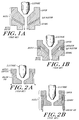
- Figs. 1a and 1b A typical such nozzle of the type manufactured by Hypertherm, Inc. is illustrated in a simplified schematic form in Figs. 1a and 1b.
- Fig. 1a corresponding to Hypertherm Models HT400 0.099, HT400 0.166 and PAC500 0.187, the front face of the nozzle is made of a ceramic. This arrangement controls gouging and double arcing because (1) the ceramic nozzle face is non-conducting and therefore will not cause double arcing and (2) the nozzle is protected by the ceramic barrier.
- FIG. 1b shows a variation on the high-current, multi-component nozzle similar to the nozzle sold by Hypertherm as its Model PAC500 0.250.
- the key to the solution is radial water injection, but the ceramic nozzle piece is replaced by a copper front piece.
- An insulating element separates the nozzle components so that the front of the nozzle is floating electrically. The copper is more readily cooled than the ceramic and it withstands abuse significantly better, and therefore has a longer life.
- Molten metal can, and does, deflect the plasma arc so that it gouges the nozzle and can, and does, build up on the nozzle face causing double arcing. Because this nozzle is comparatively inexpensive to fabricate, industry practise is to accept nozzle destruction and to replace the nozzle periodically. A typical life for a nozzle of this type, operating at 40-50 amperes, is about 1 hour of operation when used to pierce 6.35mm (1/4 inch) mild steel.
- Fig. 2a shows, in simplified schematic form, a typical one-piece, low-current nozzle of this type. As shown, a cooling gas flow is typically along the outer surface of the nozzle toward the workpiece. Nozzles of this type are sold by Hypertherm, Inc. as its Model Nos. HT40 0.038 and MAX100 0.059. There have been attempts to protect low-current, single-piece nozzles. One attempt is shown in Fig. 2b. A ceramic insulating sleeve is attached to the outside of the nozzle. This is a so-called "shield cup". Its main purpose is to stop nozzle-to-workpiece contact. An operator can then touch or drag the torch on the workpiece without double arcing.
- This ceramic sleeve offers no protection during piercing against molten metal splatter and the attendant gouging and double arcing problems. Also, the ceramic shield (1) is brittle and breaks easily and (2) not having the protection of water cooling, is attached by the molten metal ejected from the cut.
- Another object of this invention is to provide a plasma arc torch and method with the foregoing advantages that uses gas cooling, but where the gas exiting the nozzle during cutting does not interfere with the cutting action of the arc or degrade the quality of the cut.
- a further object of the present invention is to provide the foregoing advantages with a single piece nozzle.
- Another object of the present invention is to provide the foregoing advantages using replaceable components and standard materials that can be adapted to retrofit existing plasma arc torches which have no piercing protection.
- Yet another object of the invention is to provide the foregoing advantages while maintaining a favourable cost of manufacture.
- a plasma arc cutting torch has a body, an electrode mounted within the body, and a nozzle mounted on the body at a lower end of the torch adjacent a workpiece to be cut.
- a space between the electrode and the nozzle defines part of a primary gas flow path for gas that is ionized to produce a plasma arc.
- the body has internal passages to supply the primary gas, and the nozzle has an outlet orifice from which the plasma arc exits the torch once the arc transfers to the workpiece for piercing.
- the torch also includes conductors which introduce a direct current, typically in the range of 0-200 amperes, to the electrode-nozzle pair.
- a cup-like shield formed of a material with a large thermal conductivity, preferably copper, is mounted on the lower end of the torch to substantially enclose the nozzle, in spaced relationship, except for (i) a central exit orifice that is generally aligned with the nozzle orifice and (ii) at least one and preferably plural bleed holes equiangularly spaced around the exit orifice and lying in the front face of the shield immediately opposite the workpiece.
- a mounting ring formed of a dielectric material supports the shield and insulates it electrically from the body so that the shield is electrically "floating".
- a secondary gas flow path through the torch body directs a flow of cooling gas to the space between the nozzle and the shield.
- the secondary flow first enters a plenum formed in the body by a cap threaded onto the body which in turn supports the dielectric mounting ring.
- the plenum feeds the cooling gas through a set of canted ports formed in a flange of the cap swirl the secondary gas flow.
- a portion of the swirling flow exits the torch via the bleed holes formed in the front face of the shield.
- the remaining gas flow is directed to and stabilises the plasma arc.
- the flow cools the front face of the shield.
- the number and dimensions of the bleed holes, the exit orifice diameter, the shield-nozzle spacing and the secondary gas flow rate are correlated empirically for each application to produce the aforementioned stabilisation and a sufficient cooling of the shield to resist the adherence or fusion of molten metal on the shield.
- the upper edge of the shield at the exit orifice is preferably rounded to facilitate the smooth merging and exit from the torch of the remaining cooling gas flow and the plasma arc (the ionised primary gas flow).
- the bleed ports are angled away from the plasma arc preferably at an angle of 5° to 90° from the vertical (the direction of the arc, transverse to the metal workpiece).
- the angle is most preferably about 55° and formed by a straight cylindrical bore in an angled side wall of the nozzle shield.
- the degree of angling, whether of the bore, the side wall, or some combination of both, is correlated with the particular application to ensure that the excess secondary cooling gas exiting through the bleed ports does not interfere with the action of the arc in making the cut.
- the secondary gas flow line preferably also includes a mechanism to change the flow rate of the secondary cooling gas quickly and reliably in order to adjust to changes in the operating conditions of the torch.
- an electrically actuated valve in one parallel branch in the flow line allows a heavy flow when the valve is open. This condition provides a substantial cooling of the nozzle sufficient to protect the nozzle even under the extremely hostile conditions experienced on piercing a metal workpiece. After piercing, this valve closes and the secondary gas flows through a second parallel branch containing another valve that is set to allow a much smaller flow, suitable for normal cutting of the workpiece without the cooling gas degrading the cut quality.
- a gas flow has been found to be sufficient to cool the shield sufficiently to prevent its destruction by the molten metal or the plasma itself despite the fact that the specific heat of the gas is many times smaller than that of cooling liquids, especially water.
- the flow has also been found to significantly improve the quality of the cut made by the torch.
- the bleed ports and exit orifice are relatively small openings so that the shield blocks substantially all of the molten metal that would otherwise quickly destroy the nozzle. Locating the bleed ports in the side wall of the nozzle shield rather than its front face opposite the workpiece also aids in shielding the nozzle from splattered molten metal.
- the present invention involves the steps of blocking the molten metal ejected from the cut from reaching the nozzle using a shield, cooling the shield with a secondary gas flow, and bleeding off a portion of the flow to enhance the total flow rate, swirling the flow at a sufficient velocity and mass flow rate to provide a cut of good quality and directing the bled-off flow away from the arc to avoid interfering with the cut.
- the process preferably also includes the step of controlling the secondary gas flow rate as a function of the operations performed by the torch.
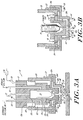
- Figs. 3a and 3b show in simplified form a plasma arc torch 10 constructed according to EP 0 375 747.
- the torch 10 has a body 12, and electrode 14, a nozzle 16 with a nozzle orifice 18, a cap 20 threaded onto the body and an insulating ring 22 threaded or otherwise secured on the cap.
- a plasma arc 24 impinges on a workpiece 26, e.g. a thick sheet of mild steel where it pierces the metal creating a cut kerf 27.
- Molten metal at the site of the piercing initially is ejected laterally, but as the cut becomes deeper into the workpiece, molten metal 26a is ejected more vertically so that it is directed back towards the nozzle 16.
- the ejection of molten metal from the workpiece to the nozzle is most severe, and most likely to damage the nozzle, during this initial piercing.
- the molten metal can run out of the kerf under the force of gravity. Therefore, during cutting it becomes less critical to cool the nozzle, but more critical to avoid interference between the cooling gas exiting the nozzle and the cutting action of the arc in the kerf.
- the body 12 is a generally solid, cylindrical single piece with various internal passages and recesses to provide the necessary fluid flow passages and electrical connections, whether alone or in co-operation with other components.
- the body can be formed of multiple pieces with any of a wide variety of configurations provided that they provide the necessary support functions and form the necessary internal passages.
- a current ring 28 is secured to the outer surface of the body 12 in a circumferential recess 12a.
- the current ring is formed of a material that has good electrical conductivity properties, such as brass, and is in electrical connection with a pilot arc lead 30 which passes through the upper end (as shown) of the body 12.
- the cap 20 is also formed of a good conductor, such as copper or brass, and closes a pilot arc circuit to the nozzle 16 which is clamped in place, replaceably, between a cap flange 20a and a circular recess 12b formed on the lower end of the body 12.
- the recess 12b and cap 20 also align the nozzle radially within the torch.
- the body also has a central bore 12c that holds the electrode 14 replaceably in electrical connection with a current lead 32 that also passes through the upper end of the body 12.
- the recess 12b also aligns the electrode so that it is generally uniformly spaced from the interior surface of the nozzle to define there between a plasma chamber 34.
- a gas tube 36 passes through the body 12 to direct a primary flow of a conventional gas, such a nitrogen, to the chamber where it is ionized and forms plasma arc 24 exiting the nozzle orifice 18.
- a nozzle shield 38 is threaded at its upper side wall 38a to the insulating ring 22.
- the shield has a stepped, cup-like configuration including a lower, generally cylindrical side wall 38b, a front face 38c, and a recessed front face 38d that spans and connects the side walls 38a and 38b.
- the shield is preferably machined as an integral component from a metal with a high thermal conductivity. Copper is preferred.
- the shield 38 is configured so that it is spaced from the cap flange 20a and the nozzle to define a gas flow passage 40.
- the front face 38c of the shield has an exit orifice 42 aligned with the nozzle orifice 18 to provide a clear exit path for the plasma arc. It also includes a set of generally equiangularly spaced holes 44 spaced radially from the exit orifice.
- a secondary gas flow path 46 directs a flow 48 of a cooling gas, such as nitrogen, from a supply tube 50 passing through the body 12 to a plenum chamber 52 (defined by the cap, the opposite outer wall of the torch body, and the clamped portion of the nozzle) and then through a set of ports 54 found in the cap 20a to the space 40.
- the plenum chamber 52 provides a local reservoir of gas that isolates the flow through the space 40 from transient fluctuations in the gas pressure or flow rate in the supply tube 50.
- the ports 54 are preferably equiangularly spaced and sized to produce a sufficient gas flow rate through the space 40 to cool the shield 38 to a degree that inhibits the adherence of ejected molten metal.
- the ports are also angled circumferentially to induce a swirling motion in the gas flow 48 through the passage 40.
- This swirling has been found to be significantly related to the quality of the cut kerf produced in the workpiece by the plasma arc.
- the degree of angling of these ports is related to the gas flow rate. With known torches, and for typical cutting operations, and angling of 1° to 5°, and preferably 2°, has been found to be preferable.
- the holes 44 bleed off a portion of the gas flow 48 to allow an enhanced flow rate, and therefore increased cooling.
- the remaining gas flow 48a which swirls inwardly from the bleed holes 44 to the exit orifice 42 (1) cools the front face 38c and (2) stabilizes the plasma arc, that is, it assists in controlling the location and diameter of the arc so that it does not attack and gouge either the nozzle or the shield.
- the upper edge of the exit orifice is rounded to smooth the transition of the remaining gas flow 48a as it encounters and interacts with the plasma arc, and then flows downwardly out of the exit orifice 42.
- Figs. 4-6 illustrate a commercial form of the torch 10 shown schematically in Figs. 3a and 3b, like parts having the same reference numbers.
- the shield has a planar front face as shown in Figs. 3a and 3b.
- the shield has a front face with radially directed recesses associated with each bleed hole 44. This arrangement reduces the likelihood of ejected molten metal attacking the nozzle by passing through one of the holes, or blocking the hole.
- Fig. 6 shows the lower end of the torch of Fig. 4 when it is assembled. The electrode leads and gas passages are not shown.
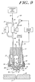
- Fig. 9 shows a form of the torch 10 constructed according to the present invention.
- the torch is substantially the same as the torch shown in Fig. 3a except that (1) the nozzle shield 38 is designed with the outwardly directed holes 44 formed in a side wall 38b that is inclined and (2) the secondary gas flow line 50 is fed through a flow control system 60.
- the holes 44 are preferably drilled directly through the side wall 38b and are at an angle A with respect to the "vertical” which is greater than zero degrees, but preferably is about 55°.
- vertical is defined as the direction of longitudinal axis of the torch which is generally aligned with the arc and is transverse to the surface of the workpiece. The precise angle selected depends on the gas flow rate and the cutting conditions.
- the perpendicular bore in an inclined wall has been found to be a somewhat superior design in terms of directing a flow that is as laminar as possible, while also effectively bleeding off a desired portion of the flow and achieving the desired cooling of the nozzle shield.
- the flow control system 60 includes two parallel branch conduits 62 and 64 both fed by a common supply of the secondary gas and both feeding the same secondary gas supply line 50.
- the branch 62 has an in-line electrically actuated valve 66 that moves between a closed position and a fully open position. In the open position, the valve 66 passes a heavy gas flow to the line 50 which produces a large degree of cooling of the nozzle shield to protect the shield during piercing.
- the secondary gas flow 48 through the valve 66 and the line 50 is typically 1.133 x 10 ⁇ 1m3/s (240scfm).
- valve 66 When the workpiece is pierced and normal cutting begins, an electrical signal S applied over lines 68 closes valve 66.
- the secondary gas flow is then diverted exclusively through branch 64 containing a manually adjustable, in-line set valve 70.
- This valve is adjusted so that when valve 66 is closed, it meters a comparatively light secondary gas flow to the line 50 which is sufficient to cool the nozzle, but which does not interfere to any significant degree with the action of the arc in the kerf 27.
- this lighter "cutting" gas flow is typically 1.9x10 ⁇ 3 m3/s (4scfm).
- the sharp step adjustment produced by valving the gas flow between branch 62 and 64, or branch 64 only, adjustment of valve 70 allows a fine tuning of the light flow through branch 64 to ensure the proper level of cooling and a good cut quality.
- This step flow gas control also allows the swirl ports 54 to be angled much more severely than would otherwise be possible, typically canted at 10°. Without a step flow, the heavy gas flow required to cool the nozzle on piercing required that the swirl ports be comparatively straight. However, then during a lighter flow associated with normal cutting, these "straight" ports produce comparatively little swirl, with a corresponding deterioration in the quality of the cut.
- the torch In operation, the torch is positioned over the workpiece 26 at a nozzle-to-workpiece standoff that it typically in the range of 2.54 - 5.05mm (0.100 to 0.200 inch). The precise distance varies with the current and other operating parameters, as is well known in the industry.
- the current path is in a pilot arc mode: current flows from the current lead 32 through the electrode 14, the nozzle 16, the cap 20, and the current ring 28 to the pilot arc lead 30.
- the current is in the range of 0-200 amperes, but can exceed 200 amperes.
- the torch is between the nozzle and the workpiece. When this ionization occurs, a pilot arc between the electrode and the nozzle transfers from the nozzle to the workpiece.
- a relay 56 is then opened on the pilot arc lead 30 so that the current path of the transferred arc is then from the current lead 32, through the electrode 14 and to the workpiece 26 via the plasma arc 24.
- the arc ignition there is a primary gas flow 58 through the tube 36 and plasma chamber 34.
- the flow preferably is swirling.
- the secondary gas flow 48 is also initiated.
- the ports 54 swirl the flow 48 which then proceed through the passage 40, with a portion of the flow being bled off through the holes 44.
- the secondary gas flow in the passage 40 cools the nozzle and the shield; the remaining gas flow 48a cools the front face 38c of the shield and stabilizes the plasma arc.
- the plasma arc heats the workpiece, it melts the metal and the molten metal 26a is ejected out of the developing "crater" at relatively high velocities as shown in Fig. 7.
- the forming crater is relatively shallow and the molten metal is ejected wide of the shield 38.
- the molten metal ejected in an increasingly vertical trajectory.
- the shield has a high thermal conductivity, it can be cooled by the gas flow 48 to a degree that the molten metal does not attack the shield, and adherence is controlled. (although some metal may adhere, when the torch cools after a cut, tapping the shield will cause the metal to fall off).
- valve 66 On piercing, the valve 66 will be open to preferentially direct the secondary gas flow to the torch. When the piercing is complete, as sensed by a change in the current being drawn by the torch in a manner well known to those skilled in the art, the valve 66 closes and the secondary cooling gas flow is decreased in a step-wise manner to a level set by the valve 70.
- the precise gas flow rate and the dimensions of the various passages, orifices, ports and holes will vary in an interrelated manner and depending on the operating parameters. For example, a larger current will, in general, require a larger secondary gas flow rate to cool the torch and stabilize the arc.
- the exit orifice should be large enough not to interfere with the egress of the plasma arc, it should also be sufficiently small that the remaining gas flow 48a interacts with the arc to provide the desired stabilization.
- the secondary gas flow rate and velocity that are optimal for the piercing and cutting modes of operation vary for each torch and with different operating conditions to produce a degree of swirling which results in the best possible cut.
- the precise values for a given torch and application are determined empirically. By way of illustration, but not of limitation, for a 100 ampere torch with a nozzle orifice diameter of 1.5mm (0.059 inch), the exit orifice is preferably about 4.32mm (0.170 inch).
- a plasma arc cutting torch with an electrically neutral metallic nozzle shield operating in conjunction with a secondary flow of cooling gas that protects the nozzle from gouging and double arcing due to molten metal ejected from the cut kerf.
- the torch includes systems to ensure that the cooling gas flow is large enough to protect the nozzle during piercing, but is changed in a step-fashion to a small enough valve to avoid interference with the cutting operation after the piercing. These systems are readily retrofit onto existing torches and have a favorable cost of manufacture.
- the secondary gas flow is described as having an independent supply and delivery path from the main gas flow, it is possible to divert a portion of the main gas flow to create the secondary gas flow.
- the shield has been described as having a cup-like configuration, the invention is not limited to any one configuration for the shield, or any particular arrangement for mounting the shield, as long as the shield is effective in mechanically blocking the molten metal, can be cooled effectively with a gas flow, and preferably also produces a gas-plasma arc interaction that stabilizes the arc.
Landscapes
- Engineering & Computer Science (AREA)
- Physics & Mathematics (AREA)
- Plasma & Fusion (AREA)
- Spectroscopy & Molecular Physics (AREA)
- Mechanical Engineering (AREA)
- Geometry (AREA)
- Plasma Technology (AREA)
- Arc Welding In General (AREA)
Applications Claiming Priority (3)
| Application Number | Priority Date | Filing Date | Title |
|---|---|---|---|
| US395266 | 1989-08-17 | ||
| US07/395,266 US5120930A (en) | 1988-06-07 | 1989-08-17 | Plasma arc torch with improved nozzle shield and step flow |
| EP90912223A EP0487573B1 (fr) | 1989-08-17 | 1990-07-10 | Appareil de coupage au jet de plasma muni d'un ecran pour le diffuseur et d'un regulateur de flux ameliores |
Related Parent Applications (2)
| Application Number | Title | Priority Date | Filing Date |
|---|---|---|---|
| EP90912223A Division EP0487573B1 (fr) | 1989-08-17 | 1990-07-10 | Appareil de coupage au jet de plasma muni d'un ecran pour le diffuseur et d'un regulateur de flux ameliores |
| EP90912223.6 Division | 1990-07-10 |
Publications (2)
| Publication Number | Publication Date |
|---|---|
| EP0585977A1 true EP0585977A1 (fr) | 1994-03-09 |
| EP0585977B1 EP0585977B1 (fr) | 1998-10-14 |
Family
ID=23562337
Family Applications (2)
| Application Number | Title | Priority Date | Filing Date |
|---|---|---|---|
| EP90912223A Expired - Lifetime EP0487573B1 (fr) | 1989-08-17 | 1990-07-10 | Appareil de coupage au jet de plasma muni d'un ecran pour le diffuseur et d'un regulateur de flux ameliores |
| EP93118339A Expired - Lifetime EP0585977B1 (fr) | 1989-08-17 | 1990-07-10 | Appareil de coupage au jet de plasma muni d'un écran pour le diffuseur et d'un régulateur de flux améliorés |
Family Applications Before (1)
| Application Number | Title | Priority Date | Filing Date |
|---|---|---|---|
| EP90912223A Expired - Lifetime EP0487573B1 (fr) | 1989-08-17 | 1990-07-10 | Appareil de coupage au jet de plasma muni d'un ecran pour le diffuseur et d'un regulateur de flux ameliores |
Country Status (7)
| Country | Link |
|---|---|
| US (1) | US5120930A (fr) |
| EP (2) | EP0487573B1 (fr) |
| JP (1) | JP2739522B2 (fr) |
| AU (1) | AU644807B2 (fr) |
| CA (1) | CA2065025C (fr) |
| DE (2) | DE69014304T2 (fr) |
| WO (1) | WO1991002619A1 (fr) |
Cited By (5)
| Publication number | Priority date | Publication date | Assignee | Title |
|---|---|---|---|---|
| EP0689896A1 (fr) * | 1994-06-28 | 1996-01-03 | KABUSHIKI KAISHA KOBE SEIKO SHO also known as KOBE STEEL LTD. | Procédé de soudage au plasma |
| FR2917655A1 (fr) * | 2007-06-22 | 2008-12-26 | Air Liquide | Controle du cycle de percage en coupage plasma. |
| US8941026B2 (en) | 2008-10-09 | 2015-01-27 | Kjellberg Finsterwalde Plasma Und Maschinen Gmbh | Nozzle for a liquid-cooled plasma torch, nozzle cap for a liquid-cooled plasma torch and plasma torch head comprising the same |
| EP2384097B1 (fr) | 2005-04-19 | 2018-06-27 | Hypertherm, Inc | Torche à arc au plasma fournissant une injection de flux de protection angulaire |
| WO2019025027A1 (fr) * | 2017-07-31 | 2019-02-07 | Linde Aktiengesellschaft | Procédé et dispositif de découpe de pièces à usiner au plasma |
Families Citing this family (47)
| Publication number | Priority date | Publication date | Assignee | Title |
|---|---|---|---|---|
| US5396043A (en) * | 1988-06-07 | 1995-03-07 | Hypertherm, Inc. | Plasma arc cutting process and apparatus using an oxygen-rich gas shield |
| US5695662A (en) * | 1988-06-07 | 1997-12-09 | Hypertherm, Inc. | Plasma arc cutting process and apparatus using an oxygen-rich gas shield |
| EP0790756B2 (fr) * | 1991-04-12 | 2008-08-20 | Hypertherm, Inc. | Procédé de découpe au plasma d'arc utilisant une protection de gaz riche en oxygène |
| EP0794697B2 (fr) * | 1991-04-12 | 2009-12-16 | Hypertherm, Inc. | Dispositif de découpe par plasma d'arc |
| DE4228064A1 (de) * | 1992-08-24 | 1994-03-03 | Plasma Technik Ag | Plasmaspritzgerät |
| US5278388A (en) * | 1993-06-07 | 1994-01-11 | Huang Huang Nan | Plasma welding and cutting gun for discharging plasma gas with constant outlet pressure |
| JPH07130490A (ja) * | 1993-11-02 | 1995-05-19 | Komatsu Ltd | プラズマトーチ |
| US5660743A (en) * | 1995-06-05 | 1997-08-26 | The Esab Group, Inc. | Plasma arc torch having water injection nozzle assembly |
| US5760363A (en) * | 1996-09-03 | 1998-06-02 | Hypertherm, Inc. | Apparatus and method for starting and stopping a plasma arc torch used for mechanized cutting and marking applications |
| IT242449Y1 (it) * | 1996-11-29 | 2001-06-14 | Tec Mo S R L | Torcia per taglio a plasma. |
| DE19716236C2 (de) * | 1997-04-18 | 2002-03-07 | Deutsch Zentr Luft & Raumfahrt | Plasmabrennervorrichtung |
| US6163009A (en) * | 1998-10-23 | 2000-12-19 | Innerlogic, Inc. | Process for operating a plasma arc torch |
| US6498317B2 (en) | 1998-10-23 | 2002-12-24 | Innerlogic, Inc. | Process for operating a plasma arc torch |
| US6677551B2 (en) | 1998-10-23 | 2004-01-13 | Innerlogic, Inc. | Process for operating a plasma arc torch |
| US6326583B1 (en) | 2000-03-31 | 2001-12-04 | Innerlogic, Inc. | Gas control system for a plasma arc torch |
| US6498316B1 (en) | 1999-10-25 | 2002-12-24 | Thermal Dynamics Corporation | Plasma torch and method for underwater cutting |
| US6337460B2 (en) | 2000-02-08 | 2002-01-08 | Thermal Dynamics Corporation | Plasma arc torch and method for cutting a workpiece |
| ITBO20020553A1 (it) * | 2002-08-30 | 2004-02-29 | Tec Mo S R L | Dispositivo di taglio al plasma. |
| US7141138B2 (en) * | 2002-09-13 | 2006-11-28 | Applied Materials, Inc. | Gas delivery system for semiconductor processing |
| US20040050828A1 (en) * | 2002-09-18 | 2004-03-18 | Johnathon Brasseur | Plasma arc torch vented shield system |
| US6914211B2 (en) * | 2003-02-27 | 2005-07-05 | Thermal Dynamics Corporation | Vented shield system for a plasma arc torch |
| US20060163220A1 (en) * | 2005-01-27 | 2006-07-27 | Brandt Aaron D | Automatic gas control for a plasma arc torch |
| DE102006005658A1 (de) * | 2005-05-25 | 2006-11-30 | Krämmer, Rita | Schutzvorrichtung für Schutzgasschweissbrenner |
| US20070045241A1 (en) * | 2005-08-29 | 2007-03-01 | Schneider Joseph C | Contact start plasma torch and method of operation |
| US7935909B2 (en) * | 2007-09-04 | 2011-05-03 | Thermal Dynamics Corporation | Hybrid shield device for a plasma arc torch |
| US8742284B2 (en) * | 2007-11-06 | 2014-06-03 | Institute Of Nuclear Energy Research, Atomic Energy Council | Steam plasma torch |
| US8389887B2 (en) | 2008-03-12 | 2013-03-05 | Hypertherm, Inc. | Apparatus and method for a liquid cooled shield for improved piercing performance |
| US8212173B2 (en) * | 2008-03-12 | 2012-07-03 | Hypertherm, Inc. | Liquid cooled shield for improved piercing performance |
| US8168916B2 (en) * | 2008-07-28 | 2012-05-01 | Thermal Dynamics Corporation | Enhanced piercing through current profiling |
| US8258424B2 (en) | 2009-08-20 | 2012-09-04 | The Esab Group, Inc. | Plasma torch with electrode wear detection system |
| US9949356B2 (en) | 2012-07-11 | 2018-04-17 | Lincoln Global, Inc. | Electrode for a plasma arc cutting torch |
| KR101524055B1 (ko) * | 2013-11-04 | 2015-05-29 | 김진일 | 플라즈마 노즐 고정 캡 |
| FR3020584B1 (fr) | 2014-05-02 | 2016-12-23 | Air Liquide Welding France | Procede et installation de coupage par plasma d'arc avec cycle de percage ameliore |
| EP2942144A1 (fr) * | 2014-05-07 | 2015-11-11 | Kjellberg-Stiftung | Système de brûleur pour découpage au jet plasma et utilisation de pièces d'usure pour un système de brûleur pour découpage au jet de plasma |
| US9967964B2 (en) | 2014-05-30 | 2018-05-08 | Hypertherm, Inc. | Cooling plasma cutting system consumables and related systems and methods |
| US9908195B2 (en) * | 2014-05-30 | 2018-03-06 | Hypertherm, Inc. | Plasma cutting system with efficient components |
| US11622440B2 (en) | 2014-05-30 | 2023-04-04 | Hypertherm, Inc. | Cooling plasma cutting system consumables and related systems and methods |
| KR102105235B1 (ko) * | 2014-09-16 | 2020-04-27 | 가부시키가이샤 후지 | 플라스마 가스 조사 장치 |
| DE102016214146A1 (de) * | 2016-08-01 | 2018-02-01 | Kjellberg Stiftung | Plasmabrenner |
| US10471623B2 (en) | 2016-10-18 | 2019-11-12 | Hmcc Acquireco2, Llc | Waterjet cutting system with variable liquid level |
| US10478945B2 (en) | 2017-06-14 | 2019-11-19 | Hmcc Acquireco2, Llc | Abrasive recovery assembly for a waterjet cutting system |
| GB201718387D0 (en) * | 2017-11-07 | 2017-12-20 | Univ College Dublin Nat Univ Ireland Dublin | Surface preparation |
| KR102412619B1 (ko) * | 2020-04-08 | 2022-06-24 | 한국항공우주산업 주식회사 | 플라즈마 아크 토치의 정렬 기구 |
| CN111590175A (zh) * | 2020-06-01 | 2020-08-28 | 中国石油大学(华东) | 一种石油套管切割等离子喷头 |
| CN112122778B (zh) * | 2020-09-24 | 2022-07-22 | 松山湖材料实验室 | 激光加工去除熔渣系统、方法、计算机设备及可读存储介质 |
| CN114147328B (zh) * | 2021-12-22 | 2022-12-13 | 南通阳光焊割设备有限公司 | 一种等离子弧弧焊喷嘴 |
| CN114951931B (zh) * | 2022-04-27 | 2023-01-31 | 江苏京生管业有限公司 | 一种钢结构处理用等离子焊接装置 |
Citations (5)
| Publication number | Priority date | Publication date | Assignee | Title |
|---|---|---|---|---|
| US3641308A (en) * | 1970-06-29 | 1972-02-08 | Chemetron Corp | Plasma arc torch having liquid laminar flow jet for arc constriction |
| FR2383746A2 (fr) * | 1977-03-18 | 1978-10-13 | Rolls Royce | Appareil et procede de soudage au jet de plasma |
| JPS6068156A (ja) * | 1983-09-22 | 1985-04-18 | Mitsubishi Heavy Ind Ltd | プラズマスポット溶接方法 |
| EP0256525A1 (fr) * | 1986-08-13 | 1988-02-24 | Hitachi, Ltd. | Procédé et dispositif pour soudage à l'arc de plasma |
| US4861962A (en) * | 1988-06-07 | 1989-08-29 | Hypertherm, Inc. | Nozzle shield for a plasma arc torch |
Family Cites Families (20)
| Publication number | Priority date | Publication date | Assignee | Title |
|---|---|---|---|---|
| GB1019848A (en) * | 1963-10-29 | 1966-02-09 | Ass Elect Ind | Improvements relating to plasma arc torch assemblies |
| US3272962A (en) * | 1965-05-03 | 1966-09-13 | Union Carbide Corp | Electric arc working process |
| US3575568A (en) * | 1967-06-08 | 1971-04-20 | Rikagaku Kenkyusho | Arc torch |
| JPS5236725B2 (fr) * | 1973-05-07 | 1977-09-17 | ||
| JPS5115795U (fr) * | 1974-07-24 | 1976-02-04 | ||
| JPS53142927A (en) * | 1977-05-20 | 1978-12-13 | Riyouichi Kasagi | Metal melting and injection method that does not generate contraction and distortion to film and its device |
| US4341941A (en) * | 1979-03-01 | 1982-07-27 | Rikagaku Kenkyusho | Method of operating a plasma generating apparatus |
| DE3032728A1 (de) * | 1980-08-30 | 1982-04-29 | Trumpf GmbH & Co, 7257 Ditzingen | Bearbeitungsmaschine mit thermischer schneidstrahleinrichtung, insbesondere plasmaschneidstrahleinrichtung |
| US4389559A (en) * | 1981-01-28 | 1983-06-21 | Eutectic Corporation | Plasma-transferred-arc torch construction |
| US4421970A (en) * | 1981-01-30 | 1983-12-20 | Hypertherm, Incorporated | Height sensing system for a plasma arc cutting tool |
| US4361748A (en) * | 1981-01-30 | 1982-11-30 | Couch Jr Richard W | Cooling and height sensing system for a plasma arc cutting tool |
| FR2534106A1 (fr) * | 1982-10-01 | 1984-04-06 | Soudure Autogene Francaise | Torche a plasma monogaz |
| US4521666A (en) * | 1982-12-23 | 1985-06-04 | Union Carbide Corporation | Plasma arc torch |
| SU1234104A1 (ru) * | 1983-01-10 | 1986-05-30 | Всесоюзный Научно-Исследовательский,Проектно-Конструкторский И Технологический Институт Электросварочного Оборудования | Плазменна горелка |
| SE447461B (sv) * | 1985-04-25 | 1986-11-17 | Npk Za Kontrolno Zavaratschni | Sammansatt munstycke for plasmatron |
| US4626648A (en) * | 1985-07-03 | 1986-12-02 | Browning James A | Hybrid non-transferred-arc plasma torch system and method of operating same |
| US4701590A (en) * | 1986-04-17 | 1987-10-20 | Thermal Dynamics Corporation | Spring loaded electrode exposure interlock device |
| JPS63101076A (ja) * | 1986-10-16 | 1988-05-06 | Mitsubishi Electric Corp | プラズマア−ク溶接機のア−ク起動方法 |
| JPS63180378A (ja) * | 1987-01-21 | 1988-07-25 | Matsushita Electric Ind Co Ltd | プラズマジエツト発生用ト−チ |
| US4762977A (en) * | 1987-04-15 | 1988-08-09 | Browning James A | Double arc prevention for a transferred-arc flame spray system |
-
1989
- 1989-08-17 US US07/395,266 patent/US5120930A/en not_active Expired - Lifetime
-
1990
- 1990-07-10 EP EP90912223A patent/EP0487573B1/fr not_active Expired - Lifetime
- 1990-07-10 DE DE69014304T patent/DE69014304T2/de not_active Expired - Lifetime
- 1990-07-10 JP JP2511517A patent/JP2739522B2/ja not_active Expired - Lifetime
- 1990-07-10 CA CA002065025A patent/CA2065025C/fr not_active Expired - Lifetime
- 1990-07-10 DE DE69032704T patent/DE69032704T2/de not_active Expired - Lifetime
- 1990-07-10 WO PCT/US1990/003870 patent/WO1991002619A1/fr active IP Right Grant
- 1990-07-10 AU AU61623/90A patent/AU644807B2/en not_active Ceased
- 1990-07-10 EP EP93118339A patent/EP0585977B1/fr not_active Expired - Lifetime
Patent Citations (6)
| Publication number | Priority date | Publication date | Assignee | Title |
|---|---|---|---|---|
| US3641308A (en) * | 1970-06-29 | 1972-02-08 | Chemetron Corp | Plasma arc torch having liquid laminar flow jet for arc constriction |
| FR2383746A2 (fr) * | 1977-03-18 | 1978-10-13 | Rolls Royce | Appareil et procede de soudage au jet de plasma |
| JPS6068156A (ja) * | 1983-09-22 | 1985-04-18 | Mitsubishi Heavy Ind Ltd | プラズマスポット溶接方法 |
| EP0256525A1 (fr) * | 1986-08-13 | 1988-02-24 | Hitachi, Ltd. | Procédé et dispositif pour soudage à l'arc de plasma |
| US4861962A (en) * | 1988-06-07 | 1989-08-29 | Hypertherm, Inc. | Nozzle shield for a plasma arc torch |
| US4861962B1 (en) * | 1988-06-07 | 1996-07-16 | Hypertherm Inc | Nozzle shield for a plasma arc torch |
Non-Patent Citations (1)
| Title |
|---|
| PATENT ABSTRACTS OF JAPAN vol. 9, no. 209 (M - 407)<1932> 27 August 1985 (1985-08-27) * |
Cited By (7)
| Publication number | Priority date | Publication date | Assignee | Title |
|---|---|---|---|---|
| EP0689896A1 (fr) * | 1994-06-28 | 1996-01-03 | KABUSHIKI KAISHA KOBE SEIKO SHO also known as KOBE STEEL LTD. | Procédé de soudage au plasma |
| US5599469A (en) * | 1994-06-28 | 1997-02-04 | Kabushiki Kaisha Kobe Seiko Sho | Plasma welding process |
| EP2384097B1 (fr) | 2005-04-19 | 2018-06-27 | Hypertherm, Inc | Torche à arc au plasma fournissant une injection de flux de protection angulaire |
| FR2917655A1 (fr) * | 2007-06-22 | 2008-12-26 | Air Liquide | Controle du cycle de percage en coupage plasma. |
| US8941026B2 (en) | 2008-10-09 | 2015-01-27 | Kjellberg Finsterwalde Plasma Und Maschinen Gmbh | Nozzle for a liquid-cooled plasma torch, nozzle cap for a liquid-cooled plasma torch and plasma torch head comprising the same |
| EP2175702B2 (fr) † | 2008-10-09 | 2017-01-04 | Kjellberg Finsterwalde Plasma und Maschinen GmbH | Buse pour une torche à plasma refroidie par liquide, coiffe de tuyère pour une torche à plasma et tête de torche à plasma dotée de celle-ci |
| WO2019025027A1 (fr) * | 2017-07-31 | 2019-02-07 | Linde Aktiengesellschaft | Procédé et dispositif de découpe de pièces à usiner au plasma |
Also Published As
| Publication number | Publication date |
|---|---|
| DE69032704D1 (de) | 1998-11-19 |
| WO1991002619A1 (fr) | 1991-03-07 |
| DE69032704T2 (de) | 1999-05-20 |
| EP0487573A4 (en) | 1992-07-29 |
| EP0487573A1 (fr) | 1992-06-03 |
| CA2065025A1 (fr) | 1991-02-18 |
| EP0585977B1 (fr) | 1998-10-14 |
| CA2065025C (fr) | 1995-11-07 |
| AU6162390A (en) | 1991-04-03 |
| DE69014304D1 (de) | 1995-01-05 |
| JPH05501081A (ja) | 1993-03-04 |
| AU644807B2 (en) | 1993-12-23 |
| US5120930A (en) | 1992-06-09 |
| JP2739522B2 (ja) | 1998-04-15 |
| DE69014304T2 (de) | 1995-04-06 |
| EP0487573B1 (fr) | 1994-11-23 |
Similar Documents
| Publication | Publication Date | Title |
|---|---|---|
| EP0585977B1 (fr) | Appareil de coupage au jet de plasma muni d'un écran pour le diffuseur et d'un régulateur de flux améliorés | |
| US5132512A (en) | Arc torch nozzle shield for plasma | |
| US4861962A (en) | Nozzle shield for a plasma arc torch | |
| US5756959A (en) | Coolant tube for use in a liquid-cooled electrode disposed in a plasma arc torch | |
| US5317126A (en) | Nozzle and method of operation for a plasma arc torch | |
| US7375303B2 (en) | Plasma arc torch having an electrode with internal passages | |
| EP0641269B1 (fr) | Electrode amelioree pour un chalumeau a arc de plasma a haute densite de courant | |
| EP0526560B1 (fr) | Procede de controle du flux et anneau de tourbillonnement pour un chalumeau a arc-plasma | |
| US6069339A (en) | Dual flow nozzle shield for plasma-arc torch | |
| US6096992A (en) | Low current water injection nozzle and associated method | |
| EP1324644B1 (fr) | Dispositif de coupage par plasma d'arc |
Legal Events
| Date | Code | Title | Description |
|---|---|---|---|
| PUAI | Public reference made under article 153(3) epc to a published international application that has entered the european phase |
Free format text: ORIGINAL CODE: 0009012 |
|
| 17P | Request for examination filed |
Effective date: 19931112 |
|
| AC | Divisional application: reference to earlier application |
Ref document number: 487573 Country of ref document: EP |
|
| AK | Designated contracting states |
Kind code of ref document: A1 Designated state(s): CH DE FR GB IT LI SE |
|
| 17Q | First examination report despatched |
Effective date: 19960322 |
|
| GRAG | Despatch of communication of intention to grant |
Free format text: ORIGINAL CODE: EPIDOS AGRA |
|
| GRAG | Despatch of communication of intention to grant |
Free format text: ORIGINAL CODE: EPIDOS AGRA |
|
| GRAH | Despatch of communication of intention to grant a patent |
Free format text: ORIGINAL CODE: EPIDOS IGRA |
|
| GRAH | Despatch of communication of intention to grant a patent |
Free format text: ORIGINAL CODE: EPIDOS IGRA |
|
| GRAA | (expected) grant |
Free format text: ORIGINAL CODE: 0009210 |
|
| AC | Divisional application: reference to earlier application |
Ref document number: 487573 Country of ref document: EP |
|
| AK | Designated contracting states |
Kind code of ref document: B1 Designated state(s): CH DE FR GB IT LI SE |
|
| PG25 | Lapsed in a contracting state [announced via postgrant information from national office to epo] |
Ref country code: LI Free format text: LAPSE BECAUSE OF FAILURE TO SUBMIT A TRANSLATION OF THE DESCRIPTION OR TO PAY THE FEE WITHIN THE PRESCRIBED TIME-LIMIT Effective date: 19981014 Ref country code: CH Free format text: LAPSE BECAUSE OF FAILURE TO SUBMIT A TRANSLATION OF THE DESCRIPTION OR TO PAY THE FEE WITHIN THE PRESCRIBED TIME-LIMIT Effective date: 19981014 |
|
| REG | Reference to a national code |
Ref country code: CH Ref legal event code: EP |
|
| REF | Corresponds to: |
Ref document number: 69032704 Country of ref document: DE Date of ref document: 19981119 |
|
| REG | Reference to a national code |
Ref country code: GB Ref legal event code: 727 |
|
| PG25 | Lapsed in a contracting state [announced via postgrant information from national office to epo] |
Ref country code: SE Free format text: LAPSE BECAUSE OF FAILURE TO SUBMIT A TRANSLATION OF THE DESCRIPTION OR TO PAY THE FEE WITHIN THE PRESCRIBED TIME-LIMIT Effective date: 19990114 |
|
| ET | Fr: translation filed | ||
| REG | Reference to a national code |
Ref country code: GB Ref legal event code: 711H |
|
| REG | Reference to a national code |
Ref country code: CH Ref legal event code: PL |
|
| PLBE | No opposition filed within time limit |
Free format text: ORIGINAL CODE: 0009261 |
|
| STAA | Information on the status of an ep patent application or granted ep patent |
Free format text: STATUS: NO OPPOSITION FILED WITHIN TIME LIMIT |
|
| 26N | No opposition filed | ||
| REG | Reference to a national code |
Ref country code: GB Ref legal event code: IF02 |
|
| PGFP | Annual fee paid to national office [announced via postgrant information from national office to epo] |
Ref country code: FR Payment date: 20090708 Year of fee payment: 20 |
|
| PGFP | Annual fee paid to national office [announced via postgrant information from national office to epo] |
Ref country code: GB Payment date: 20090612 Year of fee payment: 20 Ref country code: DE Payment date: 20090730 Year of fee payment: 20 |
|
| PGFP | Annual fee paid to national office [announced via postgrant information from national office to epo] |
Ref country code: IT Payment date: 20090731 Year of fee payment: 20 |
|
| REG | Reference to a national code |
Ref country code: GB Ref legal event code: PE20 Expiry date: 20100709 |
|
| PG25 | Lapsed in a contracting state [announced via postgrant information from national office to epo] |
Ref country code: GB Free format text: LAPSE BECAUSE OF EXPIRATION OF PROTECTION Effective date: 20100709 |
|
| PG25 | Lapsed in a contracting state [announced via postgrant information from national office to epo] |
Ref country code: DE Free format text: LAPSE BECAUSE OF EXPIRATION OF PROTECTION Effective date: 20100710 |