EP2667689B1 - Électrode pour chalumeau de coupe au plasma ainsi que son utilisation - Google Patents
Électrode pour chalumeau de coupe au plasma ainsi que son utilisation Download PDFInfo
- Publication number
- EP2667689B1 EP2667689B1 EP12169342.8A EP12169342A EP2667689B1 EP 2667689 B1 EP2667689 B1 EP 2667689B1 EP 12169342 A EP12169342 A EP 12169342A EP 2667689 B1 EP2667689 B1 EP 2667689B1
- Authority
- EP
- European Patent Office
- Prior art keywords
- section
- electrode
- outer diameter
- reduced
- emission insert
- Prior art date
- Legal status (The legal status is an assumption and is not a legal conclusion. Google has not performed a legal analysis and makes no representation as to the accuracy of the status listed.)
- Active
Links
- 238000005520 cutting process Methods 0.000 title claims description 15
- 239000002826 coolant Substances 0.000 claims description 14
- 239000000463 material Substances 0.000 claims description 6
- WFKWXMTUELFFGS-UHFFFAOYSA-N tungsten Chemical compound [W] WFKWXMTUELFFGS-UHFFFAOYSA-N 0.000 claims description 6
- 229910052721 tungsten Inorganic materials 0.000 claims description 6
- 239000010937 tungsten Substances 0.000 claims description 6
- 229910052802 copper Inorganic materials 0.000 claims description 5
- 229910052709 silver Inorganic materials 0.000 claims description 5
- 230000007704 transition Effects 0.000 claims description 5
- 230000015572 biosynthetic process Effects 0.000 claims description 4
- 229910052735 hafnium Inorganic materials 0.000 claims description 3
- VBJZVLUMGGDVMO-UHFFFAOYSA-N hafnium atom Chemical compound [Hf] VBJZVLUMGGDVMO-UHFFFAOYSA-N 0.000 claims description 3
- 229910001029 Hf alloy Inorganic materials 0.000 claims description 2
- 229910001080 W alloy Inorganic materials 0.000 claims description 2
- 229910045601 alloy Inorganic materials 0.000 claims description 2
- 239000000956 alloy Substances 0.000 claims description 2
- 239000011343 solid material Substances 0.000 claims description 2
- 239000011796 hollow space material Substances 0.000 claims 1
- 239000007789 gas Substances 0.000 description 38
- 239000004020 conductor Substances 0.000 description 5
- XKRFYHLGVUSROY-UHFFFAOYSA-N Argon Chemical compound [Ar] XKRFYHLGVUSROY-UHFFFAOYSA-N 0.000 description 4
- IJGRMHOSHXDMSA-UHFFFAOYSA-N Atomic nitrogen Chemical compound N#N IJGRMHOSHXDMSA-UHFFFAOYSA-N 0.000 description 4
- 238000001816 cooling Methods 0.000 description 4
- 239000010949 copper Substances 0.000 description 4
- QVGXLLKOCUKJST-UHFFFAOYSA-N atomic oxygen Chemical compound [O] QVGXLLKOCUKJST-UHFFFAOYSA-N 0.000 description 3
- 238000013461 design Methods 0.000 description 3
- 238000000034 method Methods 0.000 description 3
- 239000000203 mixture Substances 0.000 description 3
- 239000001301 oxygen Substances 0.000 description 3
- 229910052760 oxygen Inorganic materials 0.000 description 3
- XLYOFNOQVPJJNP-UHFFFAOYSA-N water Substances O XLYOFNOQVPJJNP-UHFFFAOYSA-N 0.000 description 3
- 238000003466 welding Methods 0.000 description 3
- RYGMFSIKBFXOCR-UHFFFAOYSA-N Copper Chemical compound [Cu] RYGMFSIKBFXOCR-UHFFFAOYSA-N 0.000 description 2
- 229910052786 argon Inorganic materials 0.000 description 2
- 238000010276 construction Methods 0.000 description 2
- 238000010891 electric arc Methods 0.000 description 2
- 230000017525 heat dissipation Effects 0.000 description 2
- 239000001257 hydrogen Substances 0.000 description 2
- 229910052739 hydrogen Inorganic materials 0.000 description 2
- 125000004435 hydrogen atom Chemical class [H]* 0.000 description 2
- 229910052746 lanthanum Inorganic materials 0.000 description 2
- FZLIPJUXYLNCLC-UHFFFAOYSA-N lanthanum atom Chemical compound [La] FZLIPJUXYLNCLC-UHFFFAOYSA-N 0.000 description 2
- 229910052757 nitrogen Inorganic materials 0.000 description 2
- 239000004332 silver Substances 0.000 description 2
- QCWXUUIWCKQGHC-UHFFFAOYSA-N Zirconium Chemical compound [Zr] QCWXUUIWCKQGHC-UHFFFAOYSA-N 0.000 description 1
- 238000009825 accumulation Methods 0.000 description 1
- 239000003570 air Substances 0.000 description 1
- 125000004429 atom Chemical group 0.000 description 1
- 230000008859 change Effects 0.000 description 1
- 239000011248 coating agent Substances 0.000 description 1
- 238000000576 coating method Methods 0.000 description 1
- 239000000498 cooling water Substances 0.000 description 1
- 230000008021 deposition Effects 0.000 description 1
- 238000011161 development Methods 0.000 description 1
- 230000018109 developmental process Effects 0.000 description 1
- 239000002019 doping agent Substances 0.000 description 1
- 230000000694 effects Effects 0.000 description 1
- 239000007772 electrode material Substances 0.000 description 1
- 238000010438 heat treatment Methods 0.000 description 1
- 239000011261 inert gas Substances 0.000 description 1
- 150000002500 ions Chemical class 0.000 description 1
- 239000007788 liquid Substances 0.000 description 1
- 238000002844 melting Methods 0.000 description 1
- 230000008018 melting Effects 0.000 description 1
- 238000012986 modification Methods 0.000 description 1
- 230000004048 modification Effects 0.000 description 1
- 230000007935 neutral effect Effects 0.000 description 1
- 230000008092 positive effect Effects 0.000 description 1
- 239000000843 powder Substances 0.000 description 1
- 238000003825 pressing Methods 0.000 description 1
- 230000008569 process Effects 0.000 description 1
- 230000004044 response Effects 0.000 description 1
- 229910000679 solder Inorganic materials 0.000 description 1
- 239000007787 solid Substances 0.000 description 1
- 239000007921 spray Substances 0.000 description 1
- 238000012546 transfer Methods 0.000 description 1
- 229910052726 zirconium Inorganic materials 0.000 description 1
Images


Classifications
-
- B—PERFORMING OPERATIONS; TRANSPORTING
- B23—MACHINE TOOLS; METAL-WORKING NOT OTHERWISE PROVIDED FOR
- B23K—SOLDERING OR UNSOLDERING; WELDING; CLADDING OR PLATING BY SOLDERING OR WELDING; CUTTING BY APPLYING HEAT LOCALLY, e.g. FLAME CUTTING; WORKING BY LASER BEAM
- B23K10/00—Welding or cutting by means of a plasma
-
- H—ELECTRICITY
- H05—ELECTRIC TECHNIQUES NOT OTHERWISE PROVIDED FOR
- H05H—PLASMA TECHNIQUE; PRODUCTION OF ACCELERATED ELECTRICALLY-CHARGED PARTICLES OR OF NEUTRONS; PRODUCTION OR ACCELERATION OF NEUTRAL MOLECULAR OR ATOMIC BEAMS
- H05H1/00—Generating plasma; Handling plasma
- H05H1/24—Generating plasma
- H05H1/26—Plasma torches
- H05H1/32—Plasma torches using an arc
- H05H1/34—Details, e.g. electrodes, nozzles
- H05H1/3442—Cathodes with inserted tip
-
- H—ELECTRICITY
- H05—ELECTRIC TECHNIQUES NOT OTHERWISE PROVIDED FOR
- H05H—PLASMA TECHNIQUE; PRODUCTION OF ACCELERATED ELECTRICALLY-CHARGED PARTICLES OR OF NEUTRONS; PRODUCTION OR ACCELERATION OF NEUTRAL MOLECULAR OR ATOMIC BEAMS
- H05H1/00—Generating plasma; Handling plasma
- H05H1/24—Generating plasma
- H05H1/26—Plasma torches
- H05H1/32—Plasma torches using an arc
- H05H1/34—Details, e.g. electrodes, nozzles
- H05H1/3478—Geometrical details
Definitions
- the invention relates to an electrode for plasma torches for plasma cutting and the use of the electrode for this plasma torch.
- Plasma is a thermally highly heated electrically conductive gas, which consists of positive and negative ions, electrons and excited and neutral atoms and molecules.
- plasma gas are different gases, eg. As the monatomic argon and / or the diatomic gases hydrogen, nitrogen, oxygen or air used. These gases ionize and dissociate through the energy of the plasma arc.
- the plasma jet can be greatly influenced in its parameters by the design of the nozzle and electrode. These parameters of the plasma jet are, for example, the beam diameter, the temperature, the energy density and the flow velocity of the gas.
- the plasma is usually constricted by a nozzle, which may be gas or water cooled.
- a nozzle which may be gas or water cooled.
- energy densities up to 2 x 10 6 W / cm 2 can be achieved.
- Temperatures of up to 30,000 ° C are generated in the plasma jet, which, in combination with the high flow velocity of the gas, enable very high cutting speeds on all electrically conductive materials.
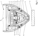
- a plasma torch essentially consists of a plasma burner head 1, an electrode 7 and a nozzle 4, further components may be an electrode holder 6 for fixing the electrode 7 and the nozzle holder 5 and the nozzle cap 2 for fixing the nozzle 4.
- the plasma gas PG is supplied through the plasma gas guide 3 into the space between the electrode 7 and the nozzle 4 and ultimately flows through the nozzle channel 4. 1 through the nozzle 4.
- Modern plasma torches additionally have a nozzle protection cap 9 and a secondary gas guide 9.1 via which a secondary gas SG is fed to the plasma jet.
- a secondary gas SG is fed to the plasma jet.
- the nozzle 4 and the electrode 7 with liquid coolant, for. B. water cooled.
- Plasma cutting is today an established method for cutting electrically conductive materials, whereby different gases and gas mixtures are used depending on the cutting task.
- electrodes 7 and nozzles 4 are used. These wear out during the operation of the plasma torch and must then be replaced.
- the plasma torches, electrodes 7 and nozzles 4 are designed so that a plasma torch can be used by replacing the electrodes 7 and nozzles 4 for different gases.
- Electrodes 7 generally consist of an electrode holder 7.1 and an emissive insert 7.2. Basically, a distinction can be made between two types. When cutting with oxygen-containing plasma gases usually a so-called flat electrode is used, ie the emission insert is 7.2 except its front emission surface in the electrode holder 7.1.
- the emissive insert 7.2 consists of hafnium or zirconium.
- As electrodes 7 for cutting with non-oxygen-containing gases or gas mixtures eg argon, hydrogen, nitrogen, tungsten, often with dopants (eg with lanthanum), is used as the material for the emission insert 7.2. This is then fixed in the electrode holder 7.1, but protrudes in contrast to the flat electrode out of this and is often referred to as a tip electrode.
- FIG. 1 Such a structure can also the FIG. 1 are taken, wherein here already an example of an electrode according to the invention is shown.
- an electrode is mounted in a holder and the electrode protrudes with its tip into a nozzle prechamber.
- the electrode material consists of tungsten and is pressed into a holder of electrically conductive material, preferably copper or silver.
- the brackets are usually water cooled to realize effective heat dissipation.
- a plasma torch with plasma gas and secondary gas supply and a nozzle and a tip electrode is described.
- the electrode consists of an electrode holder and an electrode insert, the electrode insert projects out of the electrode holder.
- the main focus is on improving the cooling of the nozzle.
- the electrodes should be cooled well, but a high temperature at the emission surface must be achieved in order to achieve a safe emission of the electrons for the formation of an arc.
- the emission should be as uniform as possible over a surface, which in turn is positive for its life. It is also important that the emission temperature after ignition of the arc is achieved in the shortest possible time.
- the electrode should be designed so that a plasma torch possible can be easily converted between the plasma gases used. Another requirement is high centricity between the emissive insert and the nozzle. This leads to better cutting results and extended life.
- a cathode assembly for an electric arc spray device is out US 2002/0144982 A1 known.
- US 5,726,414 relates to a plasma torch for welding or cutting.
- a burner for tungsten inert gas welding and an electrode for use in such a burner are known in EP 2 457 681A1 described. It is therefore an object of the invention to provide electrodes for plasma torches which can preferably be used for plasma cutting, which achieve an increased service life and at the same time have an improved response after the ignition of an arc until a temperature suitable for the emission of electrodes has been reached , According to the invention this object is achieved with an electrode for plasma torch having the features of claim 1.
- the claim 11 relates to the use of the electrode according to the invention. Advantageous embodiments and further developments can be realized with in subordinate claims.
- the electrode for plasma cutting torch according to the invention is formed from an electrode holder and an emissive insert, which are non-positively and / or positively connected with each other.
- the emission insert has at least two sections along its longitudinal axis. At least a first portion located adjacent to a fourth portion or between third and second portions has a reduced outer diameter in a rotationally symmetric formation of the emission insert or a reduced cross-sectional area in a non-rotationally symmetric emission insert relative to other portions.
- the at least one first section with reduced outer diameter or reduced cross-sectional area may be designed in the form of a groove-shaped depression, which preferably extends radially over the entire outer circumferential surface.
- Such a design of the emission insert also reduces the cross-sectional area in the region of the at least one first section with a reduced outer diameter or reduced cross-sectional area. This increases the electrical current flow in this region, so that it comes to a heating of the emission insert in a shorter time, in relation to a comparable electrical power that can be achieved in an electrode without such a first section.
- a fourth section which is subsequently arranged in the direction of a workpiece to be cut to the first section with reduced outer diameter or reduced cross-sectional area, may be tapered in the direction of the workpiece. This can be the case over its entire length. However, only a partial section or a further section, which is arranged in the direction of the workpiece, can be designed to taper conically.
- a conically tapered fourth Section may also be arranged a third section, which has a constant outer diameter or a constant cross-sectional area. At least one further fourth section, which has a conically tapered configuration, can be present at such a third section. This fourth section can then form the tip of the electrode.
- the pointing in the direction of a workpiece to be machined tip of the emission insert may be conical, pyramidal, or frusto-conical or truncated pyramid shaped.
- a in the direction of a workpiece to be machined in the form of a cone or truncated pyramid-shaped emissive insert has an in the form of a circular surface or a polygon formed in the direction of tool arranged end face. This face should be smaller than any other outer diameter or cross-sectional area of all sections present on the emissive insert.
- the first section of reduced outer diameter or reduced cross-sectional area may be formed as a rectangular, trapezoidal, part-circular or wedge-shaped recess.
- At least one cavity can be formed, into and / or can be guided by the coolant.
- the electrode holder should be made of a good electrical and heat-conducting material, preferably Ag or Cu or an alloy thereof.
- a good electrical and heat-conducting material preferably Ag or Cu or an alloy thereof.
- tungsten or a tungsten alloy or hafnium or a hafnium alloy with a melting temperature> 2000 ° C can be used as material.
- the first section of reduced outer diameter or reduced cross-sectional area formed in the form of a groove-shaped recess having a reduced outer diameter or reduced cross-sectional area should be at least 20% smaller than an outer diameter or cross-sectional area of one immediately adjacent to the reduced outer diameter or reduced cross-sectional area section second or third section.
- the emission insert should not have a continuous channel. It should be made of solid material and have no internal bore.
- the emissive insert should preferably be connected to the electrode holder by means of a press fit.
- the interference fit can be combined with a cohesive connection, preferably a solder connection.
- An electrode according to the invention can be used on a plasma torch, wherein the plasma torch is formed at least one plasma torch head, with an electrode formed from the electrode holder and the emissive insert, a nozzle, a gas gas feed and at the emission insert a first section opposite at least two adjacent to the first Section arranged portions of reduced outer diameter or reduced cross-sectional area is present.
- the outer diameter of the emissive insert can be in the range 1.5 mm to 6 mm.
- the outer diameter of the electrode holder should be correspondingly larger.
- the plasma torch may be formed in a conventional form with various modifications, which may involve, for example, a secondary gas supply or a nozzle chamber.
- the electrode may be disposed within a nozzle space.
- the in FIG. 1 Plasma torch shown at least consists of a plasma burner head 1 with an electrode 7, a nozzle 4 and a gas supply 3 for the plasma gas PG.
- the electrode 7 consists of an electrode holder 7.1 and an emissive insert 7.2, wherein the emissive insert 7.2 of the electrode 7, seen from the electrode holder 7.1, consists of at least a first section 7.23 and a torch tip tapered fourth section 7.21 and the smallest diameter of the first Section 7.23 is less than the largest diameter of the tapered fourth section 7.21. Examples of this are in the FIGS. 4 . 4.1, 4.2, 4.3, 4.4, 4.5 . 4.6 . 5, 5.1, 5.2 . 6, 6.1 . 6.2, 6.3 and 6.4 shown.
- the electrode 7 is screwed into the electrode holder 6 by means of threads and is fed from the inside with a cooling medium, which is supplied via the interior of a cooling tube 11 as a coolant flow WV and the space formed between the exterior of the cooling tube 11 and the electrode holder 5 as a coolant return WR, cooled.
- a cooling medium which is supplied via the interior of a cooling tube 11 as a coolant flow WV and the space formed between the exterior of the cooling tube 11 and the electrode holder 5 as a coolant return WR, cooled.
- the nozzle 4 is held by a nozzle cap 2, between the nozzle 4 and the nozzle cap 2 flows a cooling medium, which is returned to the coolant supply WV and the coolant return WR.
- a nozzle protection cap 9 encloses the nozzle 4 and the nozzle cap 2.
- the secondary gas SG flows through the secondary gas guide 9.1, which simultaneously isolates the nozzle protection cap 9 from the nozzle cap 2 and keeps it at a distance.
- the secondary gas guide 9.1 can be designed so that it can rotate the secondary gas SG.
- the nozzle cap 9 is fixed by a nozzle cap holder 8, which means at the plasma burner head Thread is attached.
- the plasma gas PG can be rotated by a plasma gas guide, not shown here, which is arranged between the nozzle 4 and the electrode 5.
- the electrode 7 consists of an electrode holder 7.1 and an emissive insert 7.2.
- the emission insert 7.2 is fixed in the electrode holder 7.1, this can be done non-positively or positively. Thus, a good heat transfer between the emission insert 7.2 and the electrode holder 7.1 is achieved.
- the electrode holder 7.1 may be water-cooled, wherein it may have a cavity inside, through which the cooling water flows.
- the electrode holder 7.1 consists of good heat and electrically conductive material (Cu, Ag).
- For the emissive use 7.2 tungsten, with dopings, z. B. lanthanum may be used.
- the fourth section 7.21 may be frusto-conical, truncated pyramidal, conical or pyramidal.
- the first section 7.23 can form a groove-shaped depression, which is preferably formed radially encircling the entire lateral surface of the electrode 7.
- the emissive insert 7.2 can also have several sections.
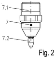
- FIG. 2 shows in schematic form an example of an electrode 7 according to the invention, consisting of an electrode holder 7.1 and an emissive insert 7.2, wherein the electrode holder 7.1 has an external thread.
- an electrode holder 7.1 is solid and may have an external thread with which the electrode 7 can be connected to the plasma torch.
- a coolant space 7.12 is formed on the electrode holder 7.1 as a simple blind hole.
- the coolant chamber 7.12 has an advantageous design, since in the area in which the emission insert 7.2 with the electrode holder 7.1 is connected, a material accumulation with a correspondingly larger surface, which is available for heat dissipation, is present.
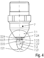
- FIGS. 4 and Figure 4.1 show an electrode 7, as with the plasma torch after FIG. 1 can be used.
- the emission insert is 7.2 with a second section 7.24, which protrudes from the electrode holder 7.1 formed.
- This second section 7.24 is followed by the first section 7.23 with a reduced outside diameter D23 in the direction of a workpiece to be machined (not shown).
- This first section 7.23 is followed by a cylindrical third section 7.22, against which the frustoconical fourth section 7.21, which tapers conically in the direction of the workpiece, abuts.
- the outer diameter D24 and D22 are the same size and larger than the outer diameter D23 of the first section 7.23 in this example.
- the outer diameter D21, the front end surface formed on the fourth portion 7.21 is smaller than the outer diameter D23 and of course the outer diameter D22 and D24.
- the outer diameters of the first, second and third sections 7.24, 7.23 and 7.22 are chosen such that D24 ⁇ D23 ⁇ D22.
- the smallest outer diameter is therefore present in the region 7.24, which is arranged directly below the electrode holder 7.1 and with which the emission insert 7.2 protrudes from the electrode holder 7.1.
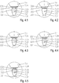
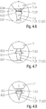
- This in Figure 4.7 Example shown has at the emission insert 7.2 again only a first section 7.23 with reduced outer diameter, which is located immediately behind the electrode holder 7.1. This is followed by a fourth section 7.21, which conically tapers in the direction of the workpiece 12 and whose largest outer diameter D22 is greater than the outer diameter D23 of the first section 7.23.
- the facing in the direction of a workpiece 12 to be machined end face of the emission insert 7.2 has a circular shape and has an outer diameter D21, which is smaller than the outer diameter D23.
- a further third section 7.22 be present, but in the direction of the longitudinal axis of the emission insert 7.2 can be very short.
- Its outer diameter D22 can be the same size as the maximum outer diameter D21 of the fourth section 7.21.
- the fourth section 7.21 is cone-shaped and has a tip towards the workpiece 12.
- the FIGS. 5 and 5.1 again show an electrode 7 with a formed in the form of a truncated cone fourth section 7.21, as in the example according to FIG. 4 , the case is.
- the conical fourth section 7.21 is conically shaped with a tip on the end of the emission insert 7. 2 facing towards the workpiece.
- the FIGS. 6 to 6.4 show examples with differently shaped section 7.23 with reduced outer diameter.
- the example after FIG. 6 again corresponds to the example FIG. 4 and the first reduced diameter section 7.23 has a rectangular cross section.
- the Figure 6.1 shows an example in which the transition of the third and second sections 7.22 and 7.24 to the first section 7.23 is formed with the radii R1 and R2.
- the transition of the first section 7.23 to the third section 7.22 is formed with a chamfer F1 and the outer diameter of the first section 7.23 with the radius R2, so that a part-circular outer contour of the first section 7.23, the deviates from the previously described rectangular shape, is formed.
- transitions of the first section 7.23 to the adjacent third and fourth sections 7.22 and 7.24 are formed as chamfers F1 and F2.
- the Figure 6.4 shows an example in which the entire first section 7.23 is formed with the radius R3 and thus correspondingly round transitions have been achieved to the third and second sections 7.22 and 7.24.
- the lengths of the individual sections 7.21, 7.22, 7.23 and 7.24 to vary in the direction of the longitudinal axis of the electrode 7 and so in addition to the respective plasma torch parameters, for example, to adjust its performance.
Claims (11)
- Électrode pour chalumeau de coupe au plasma, qui est constituée d'un support d'électrode (7.1) et d'un insert d'émission (7.2), qui sont reliés entre eux par force et/ou par complémentarité de forme,
l'insert d'émission (7.2) ne comprenant aucune alésage interne ou aucun canal traversant et comprend, le long de son axe longitudinal, au moins une première portion (7.23),
qui est disposée entre une deuxième portion (7.24) ou le support d'électrode (7.1) et une troisième portion (7.22) ou est disposée à proximité d'une quatrième portion (7.21), et présente un diamètre extérieur réduit lors d'une réalisation de l'insert d'émission (7.2) avec une symétrie de rotation ou une surface de section transversale réduite, dans le cas d'un insert d'émission (7) sans symétrie de rotation, par rapport au support d'électrode (7.1), une deuxième portion (7.24), une troisième portion (7.22) et/ou une quatrième portion (7.21),
caractérisée en ce que
la quatrième portion (7.21) se raccorde, dans la direction d'une pièce à découper, à la première portion (7.23) avec un diamètre extérieur réduit ou une surface de section transversale réduite, la quatrième portion (7.21) étant conçue de façon à se rétrécir de manière conique en direction de la pièce
ou
entre la première portion (7.23) à diamètre extérieur réduit ou surface de section transversale réduite et la quatrième portion (7.21) se rétrécissant de manière conique, est disposée la troisième portion (7.22), la troisième portion (7.22) présentant un diamètre extérieur constant ou une surface de section transversale constante. - Électrode selon la revendication 1, caractérisée en ce que l'au moins une première portion (7.23) à diamètre extérieur réduit ou surface de section transversale réduite est conçue sous la forme d'une cavité en forme de rainure, de préférence s'étendant radialement sur toute la surface d'enveloppe externe.
- Électrode selon l'une des revendications précédentes, caractérisée en ce que l'insert d'émission (7.2) présente une pointe orientée en direction de la pièce à usiner, qui présente une forme conique, pyramidale, tronconique ou la forme d'une pyramide tronquée.
- Électrode selon la revendication 3, caractérisée en ce que la face frontale disposée dans la direction d'une pièce à usiner avec un insert d'émission (7.21) sous une forme conique ou sous la forme d'une pyramide tronquée, sous la forme d'une surface circulaire ou d'un polygone, en direction d'un outil, présente une surface de section transversale qui est inférieure aux première à quatrième portions (7.21, 7.22, 7.23 et 7.24) existant sur l'insert d'émission (7.2).
- Électrode selon l'une des revendications précédentes, caractérisée en ce que la première portion (7.23) à diamètre extérieur réduit ou surface de section transversale réduite se présente sous la forme d'une cavité rectangulaire, trapézoïdale, sous la forme d'une partie de cercle ou cunéiforme.
- Électrode selon l'une des revendications précédentes, caractérisée en ce que, dans le support d'électrode (7.1) au moins un espace creux est réalisé, dans et/ou à travers lequel un fluide de refroidissement peut être guidé.
- Électrode selon l'une des revendications précédentes, caractérisée en ce que le support d'électrode (7.1) est constitué d'un matériau avec une bonne conduction électrique et thermique, de préférence Ag ou Cu ou un alliage de ceux-ci, et l'insert d'émission (7.2) est constitué de tungstène ou d'hafnium ou d'un alliage de tungstène ou d'hafnium.
- Électrode selon l'une des revendications précédentes, caractérisée en ce que la première portion (7.23) à diamètre extérieur réduit ou surface de section transversale réduite se présente sous la forme d'une cavité en forme de rainure à diamètre extérieur réduit ou surface de section transversale réduite, qui est inférieure d'au moins 20 % à un diamètre extérieur ou une surface de section transversale d'une portion (7.22 ou 7.24) disposée directement à proximité de la première portion (7.23) à diamètre extérieur réduit ou surface de section transversale réduite.
- Électrode selon l'une des revendications précédentes, caractérisée en ce que l'insert d'émission est constitué d'un matériau plein et/ou (7.2) est relié par ajustement serré avec le support d'électrode (7.1).
- Électrode selon l'une des revendications précédentes, caractérisée en ce que la transition de la première portion (7.23) avec une portion (7.22, 7.24) disposée à proximité à est réalisée l'aide d'un rayon (R1, R2, R3) et/ou un chanfrein (F1 ou F2).
- Utilisation d'une électrode selon l'une des revendications précédentes sur un chalumeau au plasma, le chalumeau au plasma comprenant au moins une tête de chalumeau au plasma (1), avec une électrode (7) constituée du support d'électrode (7.1) et de l'insert d'émission (7.2), une buse (4), une alimentation en gaz pour un gaz de plasma (PG) et sur l'insert d'émission (7.2) une première portion (7.23) avec un diamètre extérieur ou une surface de section transversale réduite par rapport à au moins une troisième portion (7.22) et/ou deuxième portion (7.24) disposée à proximité de la première portion (7.23) et l'insert d'émission (7.2) ne présente aucun alésage interne ou aucun canal traversant.
Priority Applications (11)
| Application Number | Priority Date | Filing Date | Title |
|---|---|---|---|
| EP12169342.8A EP2667689B1 (fr) | 2012-05-24 | 2012-05-24 | Électrode pour chalumeau de coupe au plasma ainsi que son utilisation |
| PL12169342T PL2667689T3 (pl) | 2012-05-24 | 2012-05-24 | Elektroda dla palnika do cięcia plazmowego i jej zastosowanie |
| ES12169342T ES2707292T3 (es) | 2012-05-24 | 2012-05-24 | Electrodo para soplete de corte por chorro de plasma, así como su uso |
| ZA2013/02710A ZA201302710B (en) | 2012-05-24 | 2013-04-16 | Electrode for plasma cutting torches and use of same |
| RU2013120729A RU2621673C2 (ru) | 2012-05-24 | 2013-05-07 | Электрод для горелок, предназначенных для плазменной резки, и его применение |
| CA2815260A CA2815260C (fr) | 2012-05-24 | 2013-05-07 | Electrode pour chalumeaux au plasma et son utilisation |
| BRBR102013012164-9A BR102013012164A2 (pt) | 2012-05-24 | 2013-05-16 | Eletrodo para maçarico de corte a plasma bem como seu uso |
| CN201310190102XA CN103418897A (zh) | 2012-05-24 | 2013-05-21 | 用于等离子割炬的电极及其用途 |
| US13/899,635 US9073141B2 (en) | 2012-05-24 | 2013-05-22 | Electrode for plasma cutting torches and use of same |
| KR1020130058077A KR102036815B1 (ko) | 2012-05-24 | 2013-05-23 | 플라즈마 절단 토치용 전극 및 그의 용도 |
| JP2013110128A JP2014004629A (ja) | 2012-05-24 | 2013-05-24 | プラズマ切断トーチ用電極及びその使用 |
Applications Claiming Priority (1)
| Application Number | Priority Date | Filing Date | Title |
|---|---|---|---|
| EP12169342.8A EP2667689B1 (fr) | 2012-05-24 | 2012-05-24 | Électrode pour chalumeau de coupe au plasma ainsi que son utilisation |
Publications (2)
| Publication Number | Publication Date |
|---|---|
| EP2667689A1 EP2667689A1 (fr) | 2013-11-27 |
| EP2667689B1 true EP2667689B1 (fr) | 2018-10-24 |
Family
ID=46178438
Family Applications (1)
| Application Number | Title | Priority Date | Filing Date |
|---|---|---|---|
| EP12169342.8A Active EP2667689B1 (fr) | 2012-05-24 | 2012-05-24 | Électrode pour chalumeau de coupe au plasma ainsi que son utilisation |
Country Status (11)
| Country | Link |
|---|---|
| US (1) | US9073141B2 (fr) |
| EP (1) | EP2667689B1 (fr) |
| JP (1) | JP2014004629A (fr) |
| KR (1) | KR102036815B1 (fr) |
| CN (1) | CN103418897A (fr) |
| BR (1) | BR102013012164A2 (fr) |
| CA (1) | CA2815260C (fr) |
| ES (1) | ES2707292T3 (fr) |
| PL (1) | PL2667689T3 (fr) |
| RU (1) | RU2621673C2 (fr) |
| ZA (1) | ZA201302710B (fr) |
Families Citing this family (5)
| Publication number | Priority date | Publication date | Assignee | Title |
|---|---|---|---|---|
| KR101497052B1 (ko) * | 2014-07-18 | 2015-02-27 | 김상국 | 이물질 절단 파쇄 기능을 갖는 수중펌프 |
| USD775249S1 (en) * | 2015-04-01 | 2016-12-27 | Koike Sanso Kogyo Co., Ltd. | Inner nozzle for plasma torch |
| DE102017112821A1 (de) * | 2017-06-12 | 2018-12-13 | Kjellberg-Stiftung | Elektroden für gas- und flüssigkeitsgekühlte Plasmabrenner, Anordnung aus einer Elektrode und einem Kühlrohr, Gasführung, Plasmabrenner, Verfahren zur Gasführung in einem Plasmabrenner und Verfahren zum Betreiben eines Plasmabrenners |
| CN108561881B (zh) * | 2018-03-16 | 2023-11-24 | 徐慕庆 | 一种割嘴 |
| DE102020125073A1 (de) | 2020-08-05 | 2022-02-10 | Kjellberg-Stiftung | Elektrode für einen Plasmaschneidbrenner, Anordnung mit derselben, Plasmaschneidbrenner mit derselben sowie Verfahren zum Plasmaschneiden |
Citations (1)
| Publication number | Priority date | Publication date | Assignee | Title |
|---|---|---|---|---|
| EP2457681A1 (fr) * | 2010-11-30 | 2012-05-30 | Kjellberg-Stiftung | Torche pour le soudage au gaz inerte et électrode tungstène et électrode destinée à être utilisée dans une telle torche |
Family Cites Families (14)
| Publication number | Priority date | Publication date | Assignee | Title |
|---|---|---|---|---|
| US3030490A (en) * | 1959-12-18 | 1962-04-17 | Union Carbide Corp | Multiple purpose arc torch apparatus |
| JPS58170174U (ja) * | 1982-05-10 | 1983-11-14 | 小池酸素工業株式会社 | プラズマト−チの電極 |
| US4675493A (en) * | 1986-01-31 | 1987-06-23 | Eutectic Corporation | Gas-constricted arc nozzle |
| JPH07130490A (ja) * | 1993-11-02 | 1995-05-19 | Komatsu Ltd | プラズマトーチ |
| US5624586A (en) * | 1995-01-04 | 1997-04-29 | Hypertherm, Inc. | Alignment device and method for a plasma arc torch system |
| EP0927594B1 (fr) * | 1997-12-23 | 2003-09-10 | Castolin S.A. | Procédé pour déposer des revêtements sur des matériaux |
| DE29905658U1 (de) * | 1999-03-26 | 1999-07-22 | Trafimet Spa | Hochfrequenz-Plasmabrenner |
| US6559407B2 (en) * | 2001-04-05 | 2003-05-06 | Ford Global Technologies, Inc. | Cathode assembly for an electric arc spray apparatus |
| DE10144516B4 (de) | 2001-09-10 | 2004-03-25 | Kjellberg Finsterwalde Elektroden Und Maschinen Gmbh | Plasmabrenner |
| US7132619B2 (en) * | 2003-04-07 | 2006-11-07 | Thermal Dynamics Corporation | Plasma arc torch electrode |
| US7375302B2 (en) * | 2004-11-16 | 2008-05-20 | Hypertherm, Inc. | Plasma arc torch having an electrode with internal passages |
| US8101882B2 (en) * | 2005-09-07 | 2012-01-24 | Hypertherm, Inc. | Plasma torch electrode with improved insert configurations |
| DE102008018530B4 (de) | 2008-04-08 | 2010-04-29 | Kjellberg Finsterwalde Plasma Und Maschinen Gmbh | Düse für einen flüssigkeitsgekühlten Plasmabrenner, Anordnung aus derselben und einer Düsenkappe sowie flüssigkeitsgekühlter Plasmabrenner mit einer derartigen Anordnung |
| KR101002082B1 (ko) * | 2010-06-17 | 2010-12-17 | 김태홍 | 플라즈마 아크 토치용 전극 |
-
2012
- 2012-05-24 ES ES12169342T patent/ES2707292T3/es active Active
- 2012-05-24 PL PL12169342T patent/PL2667689T3/pl unknown
- 2012-05-24 EP EP12169342.8A patent/EP2667689B1/fr active Active
-
2013
- 2013-04-16 ZA ZA2013/02710A patent/ZA201302710B/en unknown
- 2013-05-07 CA CA2815260A patent/CA2815260C/fr active Active
- 2013-05-07 RU RU2013120729A patent/RU2621673C2/ru active
- 2013-05-16 BR BRBR102013012164-9A patent/BR102013012164A2/pt active Search and Examination
- 2013-05-21 CN CN201310190102XA patent/CN103418897A/zh active Pending
- 2013-05-22 US US13/899,635 patent/US9073141B2/en active Active
- 2013-05-23 KR KR1020130058077A patent/KR102036815B1/ko active IP Right Grant
- 2013-05-24 JP JP2013110128A patent/JP2014004629A/ja active Pending
Patent Citations (1)
| Publication number | Priority date | Publication date | Assignee | Title |
|---|---|---|---|---|
| EP2457681A1 (fr) * | 2010-11-30 | 2012-05-30 | Kjellberg-Stiftung | Torche pour le soudage au gaz inerte et électrode tungstène et électrode destinée à être utilisée dans une telle torche |
Also Published As
| Publication number | Publication date |
|---|---|
| BR102013012164A2 (pt) | 2015-06-02 |
| US9073141B2 (en) | 2015-07-07 |
| EP2667689A1 (fr) | 2013-11-27 |
| RU2621673C2 (ru) | 2017-06-07 |
| RU2013120729A (ru) | 2014-11-20 |
| PL2667689T3 (pl) | 2019-04-30 |
| ZA201302710B (en) | 2013-12-23 |
| US20130313231A1 (en) | 2013-11-28 |
| ES2707292T3 (es) | 2019-04-03 |
| CN103418897A (zh) | 2013-12-04 |
| KR102036815B1 (ko) | 2019-11-26 |
| CA2815260C (fr) | 2020-06-02 |
| KR20130132302A (ko) | 2013-12-04 |
| CA2815260A1 (fr) | 2013-11-24 |
| JP2014004629A (ja) | 2014-01-16 |
Similar Documents
| Publication | Publication Date | Title |
|---|---|---|
| DE102008018530B4 (de) | Düse für einen flüssigkeitsgekühlten Plasmabrenner, Anordnung aus derselben und einer Düsenkappe sowie flüssigkeitsgekühlter Plasmabrenner mit einer derartigen Anordnung | |
| EP2804450B1 (fr) | Pièce isolante en plusieurs parties pour une torche à arc plasma, torche et agencements associés dotés de celle-ci et procédé associé | |
| EP2465334B1 (fr) | Capot de protection de buse et porte-capot de protection de buse ainsi que torche à plasma équipée de l'un et/ou de l'autre | |
| DE102009016932B4 (de) | Kühlrohre und Elektrodenaufnahme für einen Lichtbogenplasmabrenner sowie Anordnungen aus denselben und Lichtbogenplasmabrenner mit denselben | |
| EP2667689B1 (fr) | Électrode pour chalumeau de coupe au plasma ainsi que son utilisation | |
| DE102008062731B4 (de) | Elektrode für einen Plasmabrenner | |
| EP2849542B1 (fr) | Structure d'électrodes pour torches de coupage au plasma | |
| EP2449862A1 (fr) | Tuyère pour une torche à plasma refroidie par liquide ainsi que tête de torche à plasma munie de celle-ci | |
| EP3169472B1 (fr) | Électrode pour torche de soudage pour le soudage au tungstène sous protection gazeuse et torche de soudage pourvue d'une telle électrode | |
| EP2855071B1 (fr) | Chalumeau pour le soudage au tungstène et au gaz inerte | |
| EP0168810B1 (fr) | Chalumeau à souder pour soudage par plasma-MIG | |
| EP2457681B1 (fr) | Torche pour le soudage au gaz inerte et électrode tungstène et électrode destinée à être utilisée dans une telle torche | |
| WO2018229308A2 (fr) | Électrodes pour torches à plasma refroidies par gaz et liquide, agencement d'une électrode et d'un tube de refroidissement, guidage des gaz, torche à plasma, procédé de guidage des gaz dans une torche à plasma et procédé pour faire fonctionner une torche à plasma | |
| DE2544402C2 (de) | Plasmaschneidbrenner | |
| DE10327911B4 (de) | Plasma-MIG/MAG-Schweißbrenner | |
| EP0962277B1 (fr) | Torche de soudage à plasma | |
| WO2022028648A1 (fr) | Électrode pour un chalumeau de découpe au plasma, ensemble doté de ladite électrode, chalumeau de découpe au plasma muni de ladite électrode et procédé de découpe au plasma | |
| WO2024068182A1 (fr) | Composant tel qu'une pièce d'usure pour une torche à arc, en particulier un brûleur à plasma ou une torche de découpe au plasma, torche à arc le comprenant, et procédé de découpe au plasma | |
| EP1323339A1 (fr) | Chalumeau a plasma, notamment chalumeau a pole positif a plasma | |
| DE102008022718A1 (de) | Kathode für Plassmabrenner |
Legal Events
| Date | Code | Title | Description |
|---|---|---|---|
| PUAI | Public reference made under article 153(3) epc to a published international application that has entered the european phase |
Free format text: ORIGINAL CODE: 0009012 |
|
| 17P | Request for examination filed |
Effective date: 20130415 |
|
| AK | Designated contracting states |
Kind code of ref document: A1 Designated state(s): AL AT BE BG CH CY CZ DE DK EE ES FI FR GB GR HR HU IE IS IT LI LT LU LV MC MK MT NL NO PL PT RO RS SE SI SK SM TR |
|
| AX | Request for extension of the european patent |
Extension state: BA ME |
|
| 17Q | First examination report despatched |
Effective date: 20150423 |
|
| RAP1 | Party data changed (applicant data changed or rights of an application transferred) |
Owner name: KJELLBERG-STIFTUNG |
|
| STAA | Information on the status of an ep patent application or granted ep patent |
Free format text: STATUS: EXAMINATION IS IN PROGRESS |
|
| GRAP | Despatch of communication of intention to grant a patent |
Free format text: ORIGINAL CODE: EPIDOSNIGR1 |
|
| STAA | Information on the status of an ep patent application or granted ep patent |
Free format text: STATUS: GRANT OF PATENT IS INTENDED |
|
| INTG | Intention to grant announced |
Effective date: 20171212 |
|
| GRAJ | Information related to disapproval of communication of intention to grant by the applicant or resumption of examination proceedings by the epo deleted |
Free format text: ORIGINAL CODE: EPIDOSDIGR1 |
|
| STAA | Information on the status of an ep patent application or granted ep patent |
Free format text: STATUS: EXAMINATION IS IN PROGRESS |
|
| GRAP | Despatch of communication of intention to grant a patent |
Free format text: ORIGINAL CODE: EPIDOSNIGR1 |
|
| STAA | Information on the status of an ep patent application or granted ep patent |
Free format text: STATUS: GRANT OF PATENT IS INTENDED |
|
| INTC | Intention to grant announced (deleted) | ||
| INTG | Intention to grant announced |
Effective date: 20180220 |
|
| GRAS | Grant fee paid |
Free format text: ORIGINAL CODE: EPIDOSNIGR3 |
|
| GRAJ | Information related to disapproval of communication of intention to grant by the applicant or resumption of examination proceedings by the epo deleted |
Free format text: ORIGINAL CODE: EPIDOSDIGR1 |
|
| GRAL | Information related to payment of fee for publishing/printing deleted |
Free format text: ORIGINAL CODE: EPIDOSDIGR3 |
|
| STAA | Information on the status of an ep patent application or granted ep patent |
Free format text: STATUS: EXAMINATION IS IN PROGRESS |
|
| GRAP | Despatch of communication of intention to grant a patent |
Free format text: ORIGINAL CODE: EPIDOSNIGR1 |
|
| STAA | Information on the status of an ep patent application or granted ep patent |
Free format text: STATUS: GRANT OF PATENT IS INTENDED |
|
| INTC | Intention to grant announced (deleted) | ||
| INTG | Intention to grant announced |
Effective date: 20180704 |
|
| GRAF | Information related to payment of grant fee modified |
Free format text: ORIGINAL CODE: EPIDOSCIGR3 |
|
| GRAA | (expected) grant |
Free format text: ORIGINAL CODE: 0009210 |
|
| STAA | Information on the status of an ep patent application or granted ep patent |
Free format text: STATUS: THE PATENT HAS BEEN GRANTED |
|
| AK | Designated contracting states |
Kind code of ref document: B1 Designated state(s): AL AT BE BG CH CY CZ DE DK EE ES FI FR GB GR HR HU IE IS IT LI LT LU LV MC MK MT NL NO PL PT RO RS SE SI SK SM TR |
|
| REG | Reference to a national code |
Ref country code: GB Ref legal event code: FG4D Free format text: NOT ENGLISH |
|
| REG | Reference to a national code |
Ref country code: CH Ref legal event code: EP |
|
| REG | Reference to a national code |
Ref country code: IE Ref legal event code: FG4D Free format text: LANGUAGE OF EP DOCUMENT: GERMAN |
|
| REG | Reference to a national code |
Ref country code: AT Ref legal event code: REF Ref document number: 1058251 Country of ref document: AT Kind code of ref document: T Effective date: 20181115 |
|
| REG | Reference to a national code |
Ref country code: DE Ref legal event code: R096 Ref document number: 502012013665 Country of ref document: DE |
|
| REG | Reference to a national code |
Ref country code: NL Ref legal event code: FP |
|
| REG | Reference to a national code |
Ref country code: LT Ref legal event code: MG4D |
|
| REG | Reference to a national code |
Ref country code: ES Ref legal event code: FG2A Ref document number: 2707292 Country of ref document: ES Kind code of ref document: T3 Effective date: 20190403 |
|
| PG25 | Lapsed in a contracting state [announced via postgrant information from national office to epo] |
Ref country code: IS Free format text: LAPSE BECAUSE OF FAILURE TO SUBMIT A TRANSLATION OF THE DESCRIPTION OR TO PAY THE FEE WITHIN THE PRESCRIBED TIME-LIMIT Effective date: 20190224 Ref country code: FI Free format text: LAPSE BECAUSE OF FAILURE TO SUBMIT A TRANSLATION OF THE DESCRIPTION OR TO PAY THE FEE WITHIN THE PRESCRIBED TIME-LIMIT Effective date: 20181024 Ref country code: BG Free format text: LAPSE BECAUSE OF FAILURE TO SUBMIT A TRANSLATION OF THE DESCRIPTION OR TO PAY THE FEE WITHIN THE PRESCRIBED TIME-LIMIT Effective date: 20190124 Ref country code: HR Free format text: LAPSE BECAUSE OF FAILURE TO SUBMIT A TRANSLATION OF THE DESCRIPTION OR TO PAY THE FEE WITHIN THE PRESCRIBED TIME-LIMIT Effective date: 20181024 Ref country code: LV Free format text: LAPSE BECAUSE OF FAILURE TO SUBMIT A TRANSLATION OF THE DESCRIPTION OR TO PAY THE FEE WITHIN THE PRESCRIBED TIME-LIMIT Effective date: 20181024 Ref country code: LT Free format text: LAPSE BECAUSE OF FAILURE TO SUBMIT A TRANSLATION OF THE DESCRIPTION OR TO PAY THE FEE WITHIN THE PRESCRIBED TIME-LIMIT Effective date: 20181024 Ref country code: NO Free format text: LAPSE BECAUSE OF FAILURE TO SUBMIT A TRANSLATION OF THE DESCRIPTION OR TO PAY THE FEE WITHIN THE PRESCRIBED TIME-LIMIT Effective date: 20190124 |
|
| PG25 | Lapsed in a contracting state [announced via postgrant information from national office to epo] |
Ref country code: AL Free format text: LAPSE BECAUSE OF FAILURE TO SUBMIT A TRANSLATION OF THE DESCRIPTION OR TO PAY THE FEE WITHIN THE PRESCRIBED TIME-LIMIT Effective date: 20181024 Ref country code: PT Free format text: LAPSE BECAUSE OF FAILURE TO SUBMIT A TRANSLATION OF THE DESCRIPTION OR TO PAY THE FEE WITHIN THE PRESCRIBED TIME-LIMIT Effective date: 20190224 Ref country code: GR Free format text: LAPSE BECAUSE OF FAILURE TO SUBMIT A TRANSLATION OF THE DESCRIPTION OR TO PAY THE FEE WITHIN THE PRESCRIBED TIME-LIMIT Effective date: 20190125 Ref country code: RS Free format text: LAPSE BECAUSE OF FAILURE TO SUBMIT A TRANSLATION OF THE DESCRIPTION OR TO PAY THE FEE WITHIN THE PRESCRIBED TIME-LIMIT Effective date: 20181024 Ref country code: SE Free format text: LAPSE BECAUSE OF FAILURE TO SUBMIT A TRANSLATION OF THE DESCRIPTION OR TO PAY THE FEE WITHIN THE PRESCRIBED TIME-LIMIT Effective date: 20181024 |
|
| REG | Reference to a national code |
Ref country code: SK Ref legal event code: T3 Ref document number: E 30159 Country of ref document: SK |
|
| REG | Reference to a national code |
Ref country code: DE Ref legal event code: R097 Ref document number: 502012013665 Country of ref document: DE |
|
| PG25 | Lapsed in a contracting state [announced via postgrant information from national office to epo] |
Ref country code: DK Free format text: LAPSE BECAUSE OF FAILURE TO SUBMIT A TRANSLATION OF THE DESCRIPTION OR TO PAY THE FEE WITHIN THE PRESCRIBED TIME-LIMIT Effective date: 20181024 |
|
| PG25 | Lapsed in a contracting state [announced via postgrant information from national office to epo] |
Ref country code: RO Free format text: LAPSE BECAUSE OF FAILURE TO SUBMIT A TRANSLATION OF THE DESCRIPTION OR TO PAY THE FEE WITHIN THE PRESCRIBED TIME-LIMIT Effective date: 20181024 Ref country code: SM Free format text: LAPSE BECAUSE OF FAILURE TO SUBMIT A TRANSLATION OF THE DESCRIPTION OR TO PAY THE FEE WITHIN THE PRESCRIBED TIME-LIMIT Effective date: 20181024 Ref country code: EE Free format text: LAPSE BECAUSE OF FAILURE TO SUBMIT A TRANSLATION OF THE DESCRIPTION OR TO PAY THE FEE WITHIN THE PRESCRIBED TIME-LIMIT Effective date: 20181024 |
|
| PLBE | No opposition filed within time limit |
Free format text: ORIGINAL CODE: 0009261 |
|
| STAA | Information on the status of an ep patent application or granted ep patent |
Free format text: STATUS: NO OPPOSITION FILED WITHIN TIME LIMIT |
|
| 26N | No opposition filed |
Effective date: 20190725 |
|
| PG25 | Lapsed in a contracting state [announced via postgrant information from national office to epo] |
Ref country code: SI Free format text: LAPSE BECAUSE OF FAILURE TO SUBMIT A TRANSLATION OF THE DESCRIPTION OR TO PAY THE FEE WITHIN THE PRESCRIBED TIME-LIMIT Effective date: 20181024 |
|
| REG | Reference to a national code |
Ref country code: CH Ref legal event code: PL |
|
| GBPC | Gb: european patent ceased through non-payment of renewal fee |
Effective date: 20190524 |
|
| PG25 | Lapsed in a contracting state [announced via postgrant information from national office to epo] |
Ref country code: LI Free format text: LAPSE BECAUSE OF NON-PAYMENT OF DUE FEES Effective date: 20190531 Ref country code: CH Free format text: LAPSE BECAUSE OF NON-PAYMENT OF DUE FEES Effective date: 20190531 Ref country code: MC Free format text: LAPSE BECAUSE OF FAILURE TO SUBMIT A TRANSLATION OF THE DESCRIPTION OR TO PAY THE FEE WITHIN THE PRESCRIBED TIME-LIMIT Effective date: 20181024 |
|
| PG25 | Lapsed in a contracting state [announced via postgrant information from national office to epo] |
Ref country code: LU Free format text: LAPSE BECAUSE OF NON-PAYMENT OF DUE FEES Effective date: 20190524 |
|
| PG25 | Lapsed in a contracting state [announced via postgrant information from national office to epo] |
Ref country code: TR Free format text: LAPSE BECAUSE OF FAILURE TO SUBMIT A TRANSLATION OF THE DESCRIPTION OR TO PAY THE FEE WITHIN THE PRESCRIBED TIME-LIMIT Effective date: 20181024 |
|
| PG25 | Lapsed in a contracting state [announced via postgrant information from national office to epo] |
Ref country code: GB Free format text: LAPSE BECAUSE OF NON-PAYMENT OF DUE FEES Effective date: 20190524 Ref country code: IE Free format text: LAPSE BECAUSE OF NON-PAYMENT OF DUE FEES Effective date: 20190524 |
|
| REG | Reference to a national code |
Ref country code: AT Ref legal event code: MM01 Ref document number: 1058251 Country of ref document: AT Kind code of ref document: T Effective date: 20190524 |
|
| PG25 | Lapsed in a contracting state [announced via postgrant information from national office to epo] |
Ref country code: AT Free format text: LAPSE BECAUSE OF NON-PAYMENT OF DUE FEES Effective date: 20190524 |
|
| PG25 | Lapsed in a contracting state [announced via postgrant information from national office to epo] |
Ref country code: CY Free format text: LAPSE BECAUSE OF FAILURE TO SUBMIT A TRANSLATION OF THE DESCRIPTION OR TO PAY THE FEE WITHIN THE PRESCRIBED TIME-LIMIT Effective date: 20181024 |
|
| PG25 | Lapsed in a contracting state [announced via postgrant information from national office to epo] |
Ref country code: MT Free format text: LAPSE BECAUSE OF FAILURE TO SUBMIT A TRANSLATION OF THE DESCRIPTION OR TO PAY THE FEE WITHIN THE PRESCRIBED TIME-LIMIT Effective date: 20181024 Ref country code: HU Free format text: LAPSE BECAUSE OF FAILURE TO SUBMIT A TRANSLATION OF THE DESCRIPTION OR TO PAY THE FEE WITHIN THE PRESCRIBED TIME-LIMIT; INVALID AB INITIO Effective date: 20120524 |
|
| PG25 | Lapsed in a contracting state [announced via postgrant information from national office to epo] |
Ref country code: MK Free format text: LAPSE BECAUSE OF FAILURE TO SUBMIT A TRANSLATION OF THE DESCRIPTION OR TO PAY THE FEE WITHIN THE PRESCRIBED TIME-LIMIT Effective date: 20181024 |
|
| PGFP | Annual fee paid to national office [announced via postgrant information from national office to epo] |
Ref country code: NL Payment date: 20220519 Year of fee payment: 11 |
|
| PGFP | Annual fee paid to national office [announced via postgrant information from national office to epo] |
Ref country code: SK Payment date: 20220520 Year of fee payment: 11 Ref country code: IT Payment date: 20220524 Year of fee payment: 11 Ref country code: FR Payment date: 20220523 Year of fee payment: 11 |
|
| PGFP | Annual fee paid to national office [announced via postgrant information from national office to epo] |
Ref country code: PL Payment date: 20220513 Year of fee payment: 11 Ref country code: BE Payment date: 20220519 Year of fee payment: 11 |
|
| PGFP | Annual fee paid to national office [announced via postgrant information from national office to epo] |
Ref country code: ES Payment date: 20220725 Year of fee payment: 11 |
|
| PGFP | Annual fee paid to national office [announced via postgrant information from national office to epo] |
Ref country code: DE Payment date: 20230523 Year of fee payment: 12 Ref country code: CZ Payment date: 20230515 Year of fee payment: 12 |
|
| REG | Reference to a national code |
Ref country code: NL Ref legal event code: MM Effective date: 20230601 |
|
| REG | Reference to a national code |
Ref country code: SK Ref legal event code: MM4A Ref document number: E 30159 Country of ref document: SK Effective date: 20230524 |
|
| PG25 | Lapsed in a contracting state [announced via postgrant information from national office to epo] |
Ref country code: SK Free format text: LAPSE BECAUSE OF NON-PAYMENT OF DUE FEES Effective date: 20230524 |
|
| REG | Reference to a national code |
Ref country code: BE Ref legal event code: MM Effective date: 20230531 |
|
| PG25 | Lapsed in a contracting state [announced via postgrant information from national office to epo] |
Ref country code: SK Free format text: LAPSE BECAUSE OF NON-PAYMENT OF DUE FEES Effective date: 20230524 |
|
| PG25 | Lapsed in a contracting state [announced via postgrant information from national office to epo] |
Ref country code: NL Free format text: LAPSE BECAUSE OF NON-PAYMENT OF DUE FEES Effective date: 20230601 |