EP2175339B1 - Device for preparing plastic mixture and method for preparing plastic mixture - Google Patents
Device for preparing plastic mixture and method for preparing plastic mixture Download PDFInfo
- Publication number
- EP2175339B1 EP2175339B1 EP09161618A EP09161618A EP2175339B1 EP 2175339 B1 EP2175339 B1 EP 2175339B1 EP 09161618 A EP09161618 A EP 09161618A EP 09161618 A EP09161618 A EP 09161618A EP 2175339 B1 EP2175339 B1 EP 2175339B1
- Authority
- EP
- European Patent Office
- Prior art keywords
- component
- components
- flow
- transporting
- line
- Prior art date
- Legal status (The legal status is an assumption and is not a legal conclusion. Google has not performed a legal analysis and makes no representation as to the accuracy of the status listed.)
- Revoked
Links
Images


Classifications
-
- B—PERFORMING OPERATIONS; TRANSPORTING
- B29—WORKING OF PLASTICS; WORKING OF SUBSTANCES IN A PLASTIC STATE IN GENERAL
- B29B—PREPARATION OR PRETREATMENT OF THE MATERIAL TO BE SHAPED; MAKING GRANULES OR PREFORMS; RECOVERY OF PLASTICS OR OTHER CONSTITUENTS OF WASTE MATERIAL CONTAINING PLASTICS
- B29B7/00—Mixing; Kneading
- B29B7/74—Mixing; Kneading using other mixers or combinations of mixers, e.g. of dissimilar mixers ; Plant
- B29B7/7461—Combinations of dissimilar mixers
-
- B—PERFORMING OPERATIONS; TRANSPORTING
- B01—PHYSICAL OR CHEMICAL PROCESSES OR APPARATUS IN GENERAL
- B01F—MIXING, e.g. DISSOLVING, EMULSIFYING OR DISPERSING
- B01F25/00—Flow mixers; Mixers for falling materials, e.g. solid particles
- B01F25/40—Static mixers
- B01F25/42—Static mixers in which the mixing is affected by moving the components jointly in changing directions, e.g. in tubes provided with baffles or obstructions
-
- B—PERFORMING OPERATIONS; TRANSPORTING
- B01—PHYSICAL OR CHEMICAL PROCESSES OR APPARATUS IN GENERAL
- B01F—MIXING, e.g. DISSOLVING, EMULSIFYING OR DISPERSING
- B01F27/00—Mixers with rotary stirring devices in fixed receptacles; Kneaders
- B01F27/05—Stirrers
- B01F27/11—Stirrers characterised by the configuration of the stirrers
- B01F27/114—Helically shaped stirrers, i.e. stirrers comprising a helically shaped band or helically shaped band sections
- B01F27/1143—Helically shaped stirrers, i.e. stirrers comprising a helically shaped band or helically shaped band sections screw-shaped, e.g. worms
-
- B—PERFORMING OPERATIONS; TRANSPORTING
- B01—PHYSICAL OR CHEMICAL PROCESSES OR APPARATUS IN GENERAL
- B01F—MIXING, e.g. DISSOLVING, EMULSIFYING OR DISPERSING
- B01F33/00—Other mixers; Mixing plants; Combinations of mixers
- B01F33/80—Mixing plants; Combinations of mixers
- B01F33/82—Combinations of dissimilar mixers
- B01F33/821—Combinations of dissimilar mixers with consecutive receptacles
- B01F33/8212—Combinations of dissimilar mixers with consecutive receptacles with moving and non-moving stirring devices
-
- B—PERFORMING OPERATIONS; TRANSPORTING
- B29—WORKING OF PLASTICS; WORKING OF SUBSTANCES IN A PLASTIC STATE IN GENERAL
- B29B—PREPARATION OR PRETREATMENT OF THE MATERIAL TO BE SHAPED; MAKING GRANULES OR PREFORMS; RECOVERY OF PLASTICS OR OTHER CONSTITUENTS OF WASTE MATERIAL CONTAINING PLASTICS
- B29B7/00—Mixing; Kneading
- B29B7/30—Mixing; Kneading continuous, with mechanical mixing or kneading devices
- B29B7/58—Component parts, details or accessories; Auxiliary operations
- B29B7/72—Measuring, controlling or regulating
- B29B7/726—Measuring properties of mixture, e.g. temperature or density
-
- B—PERFORMING OPERATIONS; TRANSPORTING
- B29—WORKING OF PLASTICS; WORKING OF SUBSTANCES IN A PLASTIC STATE IN GENERAL
- B29B—PREPARATION OR PRETREATMENT OF THE MATERIAL TO BE SHAPED; MAKING GRANULES OR PREFORMS; RECOVERY OF PLASTICS OR OTHER CONSTITUENTS OF WASTE MATERIAL CONTAINING PLASTICS
- B29B7/00—Mixing; Kneading
- B29B7/30—Mixing; Kneading continuous, with mechanical mixing or kneading devices
- B29B7/58—Component parts, details or accessories; Auxiliary operations
- B29B7/72—Measuring, controlling or regulating
- B29B7/728—Measuring data of the driving system, e.g. torque, speed, power, vibration
-
- B—PERFORMING OPERATIONS; TRANSPORTING
- B29—WORKING OF PLASTICS; WORKING OF SUBSTANCES IN A PLASTIC STATE IN GENERAL
- B29B—PREPARATION OR PRETREATMENT OF THE MATERIAL TO BE SHAPED; MAKING GRANULES OR PREFORMS; RECOVERY OF PLASTICS OR OTHER CONSTITUENTS OF WASTE MATERIAL CONTAINING PLASTICS
- B29B7/00—Mixing; Kneading
- B29B7/74—Mixing; Kneading using other mixers or combinations of mixers, e.g. of dissimilar mixers ; Plant
- B29B7/7404—Mixing devices specially adapted for foamable substances
- B29B7/7433—Plants
-
- G—PHYSICS
- G05—CONTROLLING; REGULATING
- G05D—SYSTEMS FOR CONTROLLING OR REGULATING NON-ELECTRIC VARIABLES
- G05D11/00—Control of flow ratio
- G05D11/02—Controlling ratio of two or more flows of fluid or fluent material
- G05D11/13—Controlling ratio of two or more flows of fluid or fluent material characterised by the use of electric means
- G05D11/131—Controlling ratio of two or more flows of fluid or fluent material characterised by the use of electric means by measuring the values related to the quantity of the individual components
- G05D11/132—Controlling ratio of two or more flows of fluid or fluent material characterised by the use of electric means by measuring the values related to the quantity of the individual components by controlling the flow of the individual components
-
- C—CHEMISTRY; METALLURGY
- C08—ORGANIC MACROMOLECULAR COMPOUNDS; THEIR PREPARATION OR CHEMICAL WORKING-UP; COMPOSITIONS BASED THEREON
- C08L—COMPOSITIONS OF MACROMOLECULAR COMPOUNDS
- C08L63/00—Compositions of epoxy resins; Compositions of derivatives of epoxy resins
-
- C—CHEMISTRY; METALLURGY
- C08—ORGANIC MACROMOLECULAR COMPOUNDS; THEIR PREPARATION OR CHEMICAL WORKING-UP; COMPOSITIONS BASED THEREON
- C08L—COMPOSITIONS OF MACROMOLECULAR COMPOUNDS
- C08L75/00—Compositions of polyureas or polyurethanes; Compositions of derivatives of such polymers
- C08L75/04—Polyurethanes
Definitions
- the invention concerns a device for preparing plastic mixture, in particular a mixture based on epoxide, polyurethane and other resins, used in particular for the installation and renovation of railway lines, tram lines and subway lines as well as railway and road crossings, aprons, roads and motorways, and also for joining construction elements and sealing the joints between them.
- the invention relates also to the method of preparing plastic mixture, in particular a mixture based on epoxide, polyurethane and other resins, and pouring the mixture onto a site prepared in advance.
- a "Dispensing head for two-component foam with shutoff” teaches a mixing and dispensing head which is designed for use in a two component foam system.
- the head includes a body having a mixing chamber formed therein along a longitudinal axis and having a dispensing channel downstream of the mixing chamber.
- At least two supply portions are connected to the body, with each of the supply portions for supplying one of the components to the mixing chamber at a component entry location.
- Each of the component entry locations is longitudinally offset from each other.
- a rotating mixing member within the mixing chamber for mixing the components together to form the foam product.
- the mixing member includes a cylindrical core having indentations in the core and having angled vanes extending from the core.
- a shutoff portion is provided for stopping the flow of product from the dispensing channel.
- the invention concerns a device for preparing plastic mixture, consisting of at least two containers holding different plastic mixture components, especially epoxide, polyurethane and other resins as well as a curing agent, transporting lines transporting different components and pumps generating flow of the components assigned to respective transporting lines transporting separately the components, taken from assigned containers, where at least one of the components is a plastic component, to a mixing device where the components are mixed into homogeneous plastic mixture and their flow is controlled by a control system.
- plastic mixture components especially epoxide, polyurethane and other resins as well as a curing agent
- transporting lines transporting different components
- pumps generating flow of the components assigned to respective transporting lines transporting separately the components, taken from assigned containers, where at least one of the components is a plastic component
- a mixing device where the components are mixed into homogeneous plastic mixture and their flow is controlled by a control system.
- the pumps generating flow of the components are rate-adjustable pumps generating flow of the components assigned to respective transporting lines with flow meters measuring the volume of each flowing component on a continuous basis, whose indications are sent to the control system regulating the volume of each component flowing to the mixing device where the components of specific proportions are,mixed in order to achieve a substantially homogenous plastic mixture.
- a mixing device can be a mixing head with a dynamic-mixing chamber, in which there is a rotational stirrer, and, placed behind the dynamic-mixing chamber, a static-mixing chamber terminated with an outlet through which, the plastic mixture is delivered outside.
- each line transporting components, whose volume is measured on a continuous basis, there can be a switching valve redirecting the flow of a respective component to the assigned container after passing through the flow meters measuring the volume of each flowing component, and at the same time preventing the respective component from flowing into the mixing device.
- control system is able to detect stabilised parameters of the mixture composition and is able to switch flow of the components from the internal cycle into an external cycle if conditions for proper operation and correct proportions of the components are reached and is able to adjust the flow of the components in respect to pre-set volumetric or weight ratios of the components in the plastic mixture.
- each line transporting components whose volume is measured on a continuous basis, there is established a closed cycle running from the container holding the component assigned to a given transporting line, a pump generating the flow of the components in the transporting line, a flow meter measuring the volume of the flowing component on a continuous basis, a valve connected to the return line, connected to the container, redirecting the component back to the container from which it has been supplied and at the same time preventing the component from flowing via the transporting line to the mixing device, and within each line transporting components, whose volume is measured on a continuous basis, there is established an open cycle running from the container holding the component assigned to a given transporting line, a pump generating the flow of the components in the transporting line, a flow meter measuring the volume of the flowing component on a continuous basis, and a valve connected to the transporting line, connected to the mixing device, directing the component to the mixing device and at the same preventing the component from flowing to the return line, while the container holding the component assigned to a given transporting
- the rotational stirrer can be powered by a speed-adjustable motor, or engine.
- the segments of the rotational stirrer can be shaped as rectangular plates whose two opposite edges are inflected towards each other, in the planes substantially perpendicular to the axis of the rectangular plate, at an angle of about 90°, while two adjoining plates are rigidly joined by edges being in stably contact, and the angle measured in the plane substantially perpendicular to the plate axis between the edges of the adjoining plates is about 90°.
- the mixing head be provided with a cleaning nozzle, to which cleaning agent and compressed air are supplied, and/or valves preventing the components from flowing into the mixing area.
- a chamber holding inert gas which prevents the component held in the container from coming into contact with the environment.
- the mixing device can at the same time be a device supplying the plastic mixture to a pre-determined site.
- the invention relates to the process of preparing a mixture from plastics held in at least two containers with different components of plastic, especially epoxide, polyurethane and other resins as well as a curing agent, supplied via the transporting lines where flow of the component assigned to each transporting line is generated by a pump from containers to a mixing device where the components are mixed into substantially homogeneous plastic mixture and their flow is controlled by a control system.
- the flow of the component assigned to each transporting line is generated by means of a rate-adjustable pump and measured on a continuous basis by means of flow meters whose indications are sent to the control system providing regulation in real-time of the volume of each component flowing to the mixing device where the components supplied in pre-defined volumes are mixed in order to achieve a substantially homogenous plastic mixture, consistent with the pre-determined proportions of the components in the ready mixture.
- a closed cycle running from the container holding the component assigned to a given transporting line, is established by means of a valve connected to the return line, connected to the container, and the flow of the component is redirected to the container from which it has been supplied, and at the same time the component is prevented from flowing through the transporting line to the mixing device, while the pump is used to generate the flow of the components in the transporting line through the flow meter measuring the volume of the flowing component on a continuous basis, adjusting at the same time the proportions of the components transported within a given closed cycle until stable flow of the components in pre-defined volumes resulting from the pre-determined proportions of the components in the ready-to-pour mixture, is achieved, and subsequently, in the operating mode, by means of the valve connected to the transporting line, connected to the mixing device, the flow of the components is directed to the container and the pump is used to generate the flow of the
- either the pumps generating the flow of the components in the transporting lines are deactivated or the internal or closed cycle, running from the container holding the component assigned to a given transporting line, is reset by means of the valve connected to the return line, connected to the container, and the pump is used to redirect the flow of the components to the container from which the components have been supplied, and at the same time the components are prevented from flowing through the transporting line to the mixing device, and the cut-off valves are used to stop the component from flowing into the mixing area, while subsequently the mixing chamber is supplied with the cleaning agent and compressed air through the cleaning nozzle, and the component residues are removed through the outlet of the mixing device together with the cleaning agent and compressed air.
- the device for preparing plastic mixtures and pouring liquid plastics in particular polyurethane resins or epoxide resins or another resins, for which a solution according to the invention can be adapted, consists inter alia of the system for feeding, selection and monitoring of mixing proportions, system for mixing and pouring resins, automatic status control system, cleaning system, system preventing crystallization of the curing agent, material preheating system, pneumatic system and undercarriage of the device.
- a plastic mixture is a mixture composed of at least one plastic, for example polyurethane, epoxide or other resins, and at least one substance, for example a curing agent, which modifies at least one physicochemical property of the plastic present in the plastic mixture.
- Fig. 1 shows the device 1 for pouring polyurethane resins, whose systems are installed on an undercarriage, such as e.g. platform truck 10 with frame 11 provided with rotatable and turnable wheels 12.
- the wheel spacing may be changed and adapted to the conditions of the construction or renovation of track superstructures, aprons and motorways.
- the main function of the undercarriage is to bring the device as close as possible to the working site, i.e. as close as possible to the pouring site. Due to the adequate undercarriage structure, it is possible to operate the undercarriage in very narrow and inconvenient places, which is made possible by the adjustable wheel spacing.
- the presented structure of the undercarriage enables transport over rails as the undercarriage has appropriate ground clearance and good manoeuverability resulting from turn of all four wheels.
- the platform truck 10 supports the column 20 with the collapsible jib 30, fixed to the column 20 as an articulated or revolving arm by means of the bearing head 21 or a set of bearings.
- Fig. 1 shows the component A container 140 with platform 146 which supports engines of the pump and pre-mixer, the component B container 160 with an inert-gas chamber, connected at the top with an inert-gas tank, e.g. nitrogen cylinder, installed pumps, which pump the components A and B, together with a set of valves 120 and transporting lines 111, 113, and the control system 170 of the device.
- an inert-gas tank e.g. nitrogen cylinder
- Figs. 2 - 4 Further constructional details of the device for preparing the mixture and pouring polyurethane resins are shown in Figs. 2 - 4 .
- One of the systems, referred to hereinabove and shown in these figures, is the system for feeding, selection and monitoring of mixing proportions which consists of at least two containers 140, 160 for the components of the polyurethane resin mixture, where the container 140 for resin, hereinafter referred to as the component A, can be a drum with storage capacity of 200 liters, placed on a rotating platform which facilitates loading of full containers and their removal when empty by means of a set of actuators 144 controlled via the line 143.
- the drum can be used as a shipping container, supplied by the resin producer.
- the container 160 for the curing agent is a gas-tight holder with storage capacity,of e.g. 42 liters, where the curing agent, hereinafter, referred to as component B, is poured from the containers supplied by the producer.
- the upper section of the container 160 for the curing agent is designated for the inert-gas chamber 162 which is connected via a cut-off valve, to the inert-gas container 168, e.g. nitrogen cylinder.
- the resin container, 140 supports the resin-suction nozzle 142, connected to the resin feeding line whose other end is connected to the pump inlet 130.
- the pump outlet 130 is connected to the flow meter 133 which continuously sends real-time data on the recorded volume of the flowing resin, for example polyurethane, epoxide or another resin, hereinabove defined as the component A.
- the flow meter outlet is connected to the heated, at least partially, feeding line 132 of the component A, whose one end is connected to the control valve 121, e.g.
- a 3-way valve included in the main valve 120 redirecting resin either to the return line 131, terminated with the return nozzle 141 placed in the resin container 140, or to the mixing head 110 with the motor or engine 118, which means that in each line transporting components A, B, whose volume is measured on a continuous basis, there is a switching valve 121, 122 redirecting the flow of a respective component A, B to the assigned container 140, 160 after passing through the flow meters, 133, 153 respectively, which measure the volume of each flowing component A, B, and at the same time preventing the respective component from flowing to the mixing device.
- control system 190 regulating the proportions of the components in the mixture can be adapted to adjust the flow of individual components A, B to the pre-determined proportions of the components in the mixture.
- the control system 190 is a track control feedback system, i.e. signals from the flow meters 133, 153 are sent to the control system 190 which accordingly to the flow meter indications adjusts the rate of pumps 130, 150, which in turn affects the signal sent to the control system.
- the device has been provided within the transporting line of resin, i.e. component A, with the heater 135 which is one of the elements of the component heating system.
- the heater 135 is controlled by means of a dedicated temperature controller, under continuous monitoring of both the temperature controller and the microprocessor logic element 170. Heating takes place at mild temperatures and covers substantial length, e.g. three meters, as recommended by the resin producer.
- the transporting cycle of the curing agent is similar to the resin transporting cycle and comprises at least the curing agent container 160, a feeding line with the valve 161, the pump 150, the flow meter 153 installed within the feeding line 152, the main 3-way valve 122 redirecting the curing agent either to the return line 151, terminated with an outlet to the curing agent container 160, or to the stirrer 110.
- the pumps 130, 150 delivering the components A and B from the containers 140, 160 have been specially selected, and their performance specifications allow wide-ranged and precise control of their rate of delivery, which results in correct proportions of the components A and B in the final mixture, to which, if necessary, other components can also be added.
- the information necessary to determine the composition of the final mixture is sent to the mixing proportions control system 190 and to the microprocessor logic element 170, which after appropriate logic processing generates an appropriate signal for the inverters 181, 182 to achieve the correct and pre-programmed proportions of the components in the mixture.
- the components When the device has been switched on, the components, having passed through the flow meters 133, 153, are delivered to the 3 way valves 121, 122 of the main valve 120, where in the first operating mode the valve is set for the internal or closed cycle, also referred to as the small cycle, in which the unmixed components A and B are returned to the containers from which they have been supplied, as indicated by the arrows 134, 154 in Fig. 2 .
- the exact volumes are set for the components A and B delivered through pumps 130, 150, whose rate of delivery of the transported components is adjusted to the required proportions of the components A and B in the mixture used e.g. to caulk grooves between concrete slabs or areas around rails, or joints between other elements.
- the microprocessor logic element 170 which is a component of the resin mixing and pouring'system and which monitors device operations, allows switching the main valve 120 from the closed cycle to the open cycle, also referred to as the external cycle.
- the valve is switched over after a signal received from the device personnel, when the operator is ready to pour the mixture onto a prepared site.
- the procedure is carried out by means of the 3-way valves 121, 122 which are switched over simultaneously with the valves of the mixing head 110.
- the mixture components flow separately through the system of the transporting lines 111, 113, e.g.
- the device for preparing mixtures and pouring plastics, especially polyurethane resins has a specially programmed microprocessor logic element 170, the so called microcontroller, shown in Fig, 4 , which is a part of the device status automatic control system which controls and monitors operations of the device on a continuous basis.
- the device control involves verification of such parameters as the correct proportions of the mixture components, proper pressure values for individual components, appropriate temperature of the components during device operation, component content in the containers, proper position of the component A submersible pump, correct power supply to the device and condition of the electrical and logical safety devices.
- the microprocessor logic element 170 controls switching over of both the main valves and the mixing head, activation of the programmable components, including the stirrer engine, pump actuators, as well as switching on/off of the entire device. If any of the above parameters is found to be incorrect, the control system disables device operation by blocking device activation or disenabling the closed-to-open cycle switchover. All the parameters are additionally stored in the device, internal memory for maintenance purposes and to guarantee good quality of the performed casting.
- the device for preparing plastic mixtures consists of at least two containers 140, 160 holding different components A and B which form the plastic mixture, lines transporting different components from the containers to the mixing device, i.e. mixing head, where the components are mixed in order to achieve a homogenous plastic mixture.
- the transporting lines are lines made of rigid and/or flexible pipes, hoses, connectors, elbows of separators and collectors, which can include transmitting lines, return lines, feeding lines and the like.
- the flow meters 133, 153 measuring the volume of each flowing component A, B on a continuous basis, whose indications are sent to the control system 190 regulating the volume of each component flowing to the mixing device where the components in pre-set proportions are mixed in order to achieve a substantially homogenous plastic mixture.
- valve 121, 122, connected to the return line 131, 151, and the valve 121, 122, connected to the transporting line 111, 113, connected to the mixing device 110, directing the flow of the component to the mixing device 110 and at the same time preventing the component A, B from flowing to the return line 131, 151 can be the same valve formed as a 3-way valve.
- Figure 5 shows the system for preventing the crystalization of the crystalization agent, which can also be used for substances and materials which when brought in contact with air or specific gases form undesirable compounds, in particular, when in liquid plastic solid bodies are formed, which in the case of the curing agent are crystals precipitating as a result of a reaction between compounds having isocyanate group and water molecules from the air.
- the system preventing the crystallization of the curing agent consists of the air-tight container 160 with the chamber 162, also referred to as the inert-gas cushion, formed over a specific compound, containing inert gas, e.g. nitrogen, preventing the compound from coming into contact with the environment.
- the container 168 is provided with a set of reducers 167 maintaining constant pressure in the inert-gas installation.
- the inert-gas chamber 162 installed according to the presented invention over the curing agent, is connected to the inert-gas container 168 via the inert-gas line 163 having the connection valve 166, the control valve 165 and a safety valve.
- the inert-gas, pressure in the chamber 162 is controlled by means of the manometer 164.
- the lines are provided with the system preventing the crystallization of e.g. the curing agent, no precipitation of crystals occurs which could block the flow of a specific mixture component, in particular through the flow meters having ducts of small cross-section and susceptible to congestion.
- Figure 6 shows the pneumatic system where compressed air is the energy-conveying medium as it is one of the few environment-friendly materials.
- Compressed air is generated by the compact compressor 148 with a set of regulators, installed on the device undercarriage. This medium is used first of all to control ball valves by means of compressed-air actuators, to drive the actuators 144 lifting the platform from over the component A drum container, which are connected to the compressor 148 via the transporting lines 145, e.g. rigid and/or flexible pipes, the control valve 146 and the main valve 147.
- the compressed air in a device according to the invention, is used to clean the mixing head, in particular the mixing chamber and the nozzle, which is presented hereinafter.
- Fig. 7 shows the cleaning system of the device according to the invention, in particular used for cleaning of the mixing head 110, which is related to the bonding characteristics of the components mixed in the device according to the invention.
- the cleaning system of the device consists in particular,of the container 740 holding,the cleaning agent, e.g. solvent, which via the second control solenoid valve 735, cut-off valve 734 and directional valve 732 is connected by means of the flexible hoses 738 and couplers to the cleaning nozzle 730 placed in the mixing head 110.
- the container 740 for the cleaning agent is supplied, from the top, with compressed air from the compressor, the pneumatic system referred to hereinabove, via the quick-connect coupling 770, a set of reducers with the manometer 760, the first control solenoid valve 750 and the safety valve 742.
- the pressure present in the container 740 holding the cleaning agent is indicated by the control manometer 741.
- Cleaning of the mixing head 110, placed e.g. inside the protective cover 710, is supported by the compressed air supplied via the compressed-air line 737 with the cut-off valve 733, which at one end is connected, via the directional valve 731, to the cleaning nozzle, and at the other end is connected to the line running from the compressor behind the first control solenoid valve 750.
- the stirrer can be set in rotational motion by means of the engine 720.
- Figure 8 shows the mixing device according to the invention which consists of the mixing head 110, comprising in particular an approximately rectangular protective cover 810 with the pre-mixing chamber to which the mixing system 850, the cut off valves 811, 815 and the power transmission system 840 of the stirrer 860 can be connected.
- the mixing system 850 consists of the first double-threaded cylinder 851 with the dynamic-mixing chamber which contains the cylindrical slip insert 853 and the rotational stirrer 860 with the segments 852, and, placed behind the dynamic-mixing chamber, the static-mixing chamber, provided in the second cylinder 856 which at one end is terminated with an outlet, through which the plastic mixture is delivered outside, and as the outlet is connected to the static-mixing chamber, the mixing head is also a device supplying the plastic mixture to a pre-determined site.
- the second cylinder 856 has at its other, end a threaded end that allows connecting it to the first threaded cylinder by means of the connecting piece 855 and the connector 854 with a graded threaded porthole.
- the cut-off valves 811, 815 have a substantially rectangular protective cover which supports a cutting-off element which prevents the respective component from flowing to the mixing area comprising the pre-mixing, dynamic-mixing and static-mixing chambers.
- the cutting-off element can be reset into different positions, either mechanically or ele'ctrically by means of the electromagnetic systems.
- the cut-off valves 811, 815 are fixed to the protective cover 810 by means of the connecting elements 818 and covers 812, 816 having holes in which the connecting pieces 813, 817 can be screwed in, to which the lines transporting the components A and B are connected.
- the rotational stirrer 860 consists of the segments 852 shaped' as rectangular plates whose two opposite edges are inflected towards each other in the planes substantially perpendicular to the axis of the rectangular plate at an angle of about 90°, which is also the rotational axis of the rotational stirrer 850, and the adjoining plates are joined by the edges being in constant contact, while the angle measured in the plane substantially perpendicular to the plate axis between the edges of the adjoining plates is about 90°.
- the stirrer 860 is terminated with a cylindrical element which slides over the slip insert 853.
- the protective cover 810 is connected to the power transmission system 840 which transmits power to the rotational stirrer 860 from the speed-adjustable engine 720, shown in Fig. 7 , e.g. an electric, hydraulic or compressed-air engine.
- the power transmission system 840 consists in particular of the connector 842 mounted to the protective cover 810 by means of the connecting elements 843, the driving shaft 845 having at one end a notch mating with the stirrer 860, and at the other end an opening in which the coupling pin 844 connecting the driving shaft 845 with the clutch 841 can be placed.
- the mixing head 110 can be provided with the cleaning nozzle 730 shown in Fig. 7 to which the cleaning agent and compressed air are supplied.
- the cleaning nozzle can be mounted in the service line 820, to which alternatively an additional transporting line can be connected to supply other components to the device, whose volume can be held constant or regulated as in the case of the components A and B.
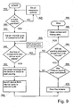
- Figure 9 shows a block diagram of the process of preparing plastic mixtures from plastics held in at least two containers with different components of the plastic mixture, supplied via the transporting lines from the containers to the mixing device where the components are mixed in order to achieve a homogeneous plastic mixture.
- start-up 910 all the device subassemblies, necessary for proper operation of the device, are activated, and subsequently in step 920 it is checked if the device is ready for operation.
- step 925 are carried out all necessary auctions to eliminate any defects, whereas, when the device is checked to be fully operational, in step 930 the internal cycle, also referred to as the closed cycle, is activated or established, starting thus the mode for determining the device working parameters and mixture composition in each line transporting the components, whose volume is measured on a continuous basis.
- the closed cycle can be a cycle running from the container holding the component assigned to a given transporting line.
- the closed cycle can be established by means of the valve connected to the return line, connected to the container, and redirecting the flow of the component to the container from which the component has been supplied, and at the same time preventing the component from flowing through the transporting line to the mixing device, while using the pump to generate the flow of the component in the transporting line through the flow meter measuring the volume of the flowing component on a continuous basis and, if necessary, adjusting in steps 940, 945 the proportions of the components flowing in a given closed cycle until stable flow of the components of pre defined volumes, resulting from the pre-determined component proportions in the ready-to-pour mixture, is achieved.
- step 950 is generated a message that the device is ready to start pouring, and subsequently in step 960 the device is switched over from the internal cycle to the external cycle of the components, the so-called open cycle, in which the device is in the operating mode.
- step 970 in the operating mode during pouring of the mixture by means of the valve connected to transporting line, connected to the mixing device, the flow of the component is directed from the container and the pump is used to generate the flow of the component in the transporting line through the flow meter to the mixing device, preventing at the same time the component from flowing to the return line, and monitoring on a continuous basis the flow of the components' of pre-defined volumes, resulting from the pre-determined proportions of the components in the mixture, while the container holding the component assigned to a given transporting line, the pump generating the flow of the component in the transporting line, the flow meter measuring the volume of the flowing component on a continuous basis, which belong to the closed cycle, are also the container holding the component assigned to a given transporting line, the pump generating the flow of the component in the transporting line, the flow meter measuring the volume of the flowing, component on a continuous basis, in the open cycle, in which the component is directed to the mixing device.
- step 980 it is checked if the pouring of the mixture is completed, and in step 985 it is checked if the pouring stoppage is going to be longer than a specific time interval, for example one minute. If it is found that the stoppage is going to be longer than the specific time interval, then the step 990 is executed to clean the area where the components are mixed.
- a specific time interval for example one minute.
- the pumps generating the flow of the components in the transporting lines are switched off or the internal or closed cycle running from the container holding the component assigned to a given transporting line is re-established or reset by means of the valve connected to the return line, connected to the container, and by means of the pump the component is redirected to the container from which the component has been supplied, and at the same time preventing the component from flowing through the transporting line to the mixing device, and by means of the cut-off valves separates the components from the mixing area, following which the mixing chamber is supplied through the cleaning nozzle with the cleaning agent and compressed air, and the component residues are removed through the outlet of the mixing device.
- the operating mode is terminated in step 995 after the mixing area or chambers have been cleaned and all device subassemblies have been deactivated.
- the presented devices provides continuous monitoring of the composition of the ready-to-pour mixture and control of the proportions of the individual components.
Landscapes
- Engineering & Computer Science (AREA)
- Mechanical Engineering (AREA)
- Chemical & Material Sciences (AREA)
- Chemical Kinetics & Catalysis (AREA)
- Physics & Mathematics (AREA)
- General Physics & Mathematics (AREA)
- Automation & Control Theory (AREA)
- Dispersion Chemistry (AREA)
- Processing And Handling Of Plastics And Other Materials For Molding In General (AREA)
- External Artificial Organs (AREA)
- Processes Of Treating Macromolecular Substances (AREA)
Priority Applications (1)
| Application Number | Priority Date | Filing Date | Title |
|---|---|---|---|
| PL09161618T PL2175339T3 (pl) | 2008-10-13 | 2009-06-01 | Urządzenie do przygotowywania mieszanki z tworzyw sztucznych i sposób przygotowania mieszanki z tworzyw sztucznych |
Applications Claiming Priority (1)
| Application Number | Priority Date | Filing Date | Title |
|---|---|---|---|
| PL386268A PL216401B1 (pl) | 2008-10-13 | 2008-10-13 | Urządzenie do przygotowania mieszanki z tworzyw sztucznych i sposób przygotowania mieszanki z tworzyw sztucznych |
Publications (2)
| Publication Number | Publication Date |
|---|---|
| EP2175339A1 EP2175339A1 (en) | 2010-04-14 |
| EP2175339B1 true EP2175339B1 (en) | 2011-11-16 |
Family
ID=40935496
Family Applications (1)
| Application Number | Title | Priority Date | Filing Date |
|---|---|---|---|
| EP09161618A Revoked EP2175339B1 (en) | 2008-10-13 | 2009-06-01 | Device for preparing plastic mixture and method for preparing plastic mixture |
Country Status (3)
| Country | Link |
|---|---|
| EP (1) | EP2175339B1 (pl) |
| AT (1) | ATE534062T1 (pl) |
| PL (2) | PL216401B1 (pl) |
Cited By (1)
| Publication number | Priority date | Publication date | Assignee | Title |
|---|---|---|---|---|
| KR101466878B1 (ko) * | 2013-07-24 | 2014-12-03 | (주) 디유티코리아 | 이중믹서가 적용된 발포성형 원료 핵생성장치 |
Families Citing this family (3)
| Publication number | Priority date | Publication date | Assignee | Title |
|---|---|---|---|---|
| CN105057269B (zh) * | 2015-08-19 | 2017-04-05 | 苏州吴江春宇电子股份有限公司 | 一种清洗生产线用清洗剂搅拌装置 |
| WO2020216681A1 (en) * | 2019-04-25 | 2020-10-29 | Covestro Intellectual Property Gmbh & Co. Kg | Mobile containment and mixing plant, and related method |
| CN113910526B (zh) * | 2021-10-11 | 2023-07-07 | 长虹美菱股份有限公司 | 一种冰箱柜用聚氨酯原料混合系统 |
Family Cites Families (8)
| Publication number | Priority date | Publication date | Assignee | Title |
|---|---|---|---|---|
| US4074363A (en) * | 1976-09-17 | 1978-02-14 | Ric-Wil, Incorporated | Apparatus for generating plastic foam |
| US4202635A (en) * | 1977-12-02 | 1980-05-13 | Hendrickson Carl E | Portable device for mixing two materials |
| ATE5519T1 (de) | 1979-11-16 | 1983-12-15 | Mti-Mischtechnik Industrieanlagen Gmbh | Mischer zum kontinuierlichen mischen von stoffen, insbesondere kunststoffen. |
| DE4038815A1 (de) | 1990-12-05 | 1992-06-11 | Bostik Gmbh | Zweikomponenten-polyurethan-dichtungsmassen und mischverfahren hierfuer |
| US5472990A (en) * | 1994-11-10 | 1995-12-05 | Dennis Chemical Co., Inc. | Method and apparatus for nucleation of polyurethane foam which results in self-adhering microcellular foam |
| US5938079A (en) * | 1995-01-27 | 1999-08-17 | Nordson Corporation | Dispensing head for two-component foam with shutoff |
| DE19738498A1 (de) | 1997-09-03 | 1999-03-04 | Bayer Ag | Verfahren zur kontinuierlichen Herstellung von thermoplastisch verarbeitbaren Polyurethanen in einem Zweiwellenextruder mit spezieller Temperaturführung |
| FR2789621B1 (fr) * | 1999-02-15 | 2001-05-04 | Secmer | Dispositif melangeur sous vide pour la coulee de materiaux plastiques polymerisables |
-
2008
- 2008-10-13 PL PL386268A patent/PL216401B1/pl unknown
-
2009
- 2009-06-01 EP EP09161618A patent/EP2175339B1/en not_active Revoked
- 2009-06-01 PL PL09161618T patent/PL2175339T3/pl unknown
- 2009-06-01 AT AT09161618T patent/ATE534062T1/de active
Cited By (1)
| Publication number | Priority date | Publication date | Assignee | Title |
|---|---|---|---|---|
| KR101466878B1 (ko) * | 2013-07-24 | 2014-12-03 | (주) 디유티코리아 | 이중믹서가 적용된 발포성형 원료 핵생성장치 |
Also Published As
| Publication number | Publication date |
|---|---|
| EP2175339A1 (en) | 2010-04-14 |
| PL386268A1 (pl) | 2010-04-26 |
| PL2175339T3 (pl) | 2012-04-30 |
| PL216401B1 (pl) | 2014-03-31 |
| ATE534062T1 (de) | 2011-12-15 |
Similar Documents
| Publication | Publication Date | Title |
|---|---|---|
| US9694372B2 (en) | Plural component coating application system with a compressed gas flushing system and spray tip flip mechanism | |
| KR920004475B1 (ko) | 다층 단열 내화 피막을 분사하기 위한 방법 및 설비 | |
| US5795060A (en) | Method and apparatus for continuous production of colloidally-mixed cement slurries and foamed cement grouts | |
| KR100292096B1 (ko) | 밀폐셀기포제조방법및장치 | |
| CN103857501B (zh) | 无溶剂双组份喷涂系统及方法 | |
| US6102304A (en) | Plural component striping spray system and method | |
| EP2175339B1 (en) | Device for preparing plastic mixture and method for preparing plastic mixture | |
| EP1031776B1 (en) | Injector/valve combination designed to improve color dosing response time | |
| US9738405B2 (en) | Resin cartridge production system | |
| US11623191B2 (en) | System for applying a building material with multiple mixers and movement device | |
| JP6588173B2 (ja) | 粘稠材料発泡装置及び粘稠材料を発泡させる方法 | |
| EP1985376A2 (en) | Apparatus and method for dispensing foam onto substrates of large width | |
| US5587182A (en) | Apparatus for the production of endless polyurethane moldings | |
| JP6960557B2 (ja) | 反応プラスチックの製造装置及び製造方法 | |
| US10625227B2 (en) | Mixer apparatus for mixing a high-viscosity fluid | |
| JPH08229939A (ja) | 二成分発泡材料を配量する方法および装置 | |
| JPH10263457A (ja) | 管更生塗料の調製装置とベースタンク及び混合機構 | |
| JPH0994450A (ja) | 流動性材料にガスを混入させる方法及び装置 | |
| US20250170538A1 (en) | Dynamic mixer for multiple component applicator | |
| CA2602890C (en) | System and method for producing resin cartridges | |
| US20250177932A1 (en) | Mixer having different diameters for applicator for producing multiple component mixture | |
| CN212096923U (zh) | 一种在线配比输送装置 | |
| JP3012549B2 (ja) | 管更生塗料の調製方法とその装置 | |
| JPH10216608A (ja) | 管更生工法と塗料の調製方法及びシステム | |
| JPH06503540A (ja) | ミキサインサートを備えた交換可能な容器 |
Legal Events
| Date | Code | Title | Description |
|---|---|---|---|
| PUAI | Public reference made under article 153(3) epc to a published international application that has entered the european phase |
Free format text: ORIGINAL CODE: 0009012 |
|
| AK | Designated contracting states |
Kind code of ref document: A1 Designated state(s): AT BE BG CH CY CZ DE DK EE ES FI FR GB GR HR HU IE IS IT LI LT LU LV MC MK MT NL NO PL PT RO SE SI SK TR |
|
| RIN1 | Information on inventor provided before grant (corrected) |
Inventor name: CHOLEWA, ARKADIUSZ Inventor name: WINIARSKI, PIOTR Inventor name: BUDZIKOWSKI, ANDRZEJ |
|
| 17P | Request for examination filed |
Effective date: 20101005 |
|
| GRAP | Despatch of communication of intention to grant a patent |
Free format text: ORIGINAL CODE: EPIDOSNIGR1 |
|
| GRAS | Grant fee paid |
Free format text: ORIGINAL CODE: EPIDOSNIGR3 |
|
| GRAA | (expected) grant |
Free format text: ORIGINAL CODE: 0009210 |
|
| AK | Designated contracting states |
Kind code of ref document: B1 Designated state(s): AT BE BG CH CY CZ DE DK EE ES FI FR GB GR HR HU IE IS IT LI LT LU LV MC MK MT NL NO PL PT RO SE SI SK TR |
|
| REG | Reference to a national code |
Ref country code: GB Ref legal event code: FG4D |
|
| REG | Reference to a national code |
Ref country code: CH Ref legal event code: EP |
|
| REG | Reference to a national code |
Ref country code: IE Ref legal event code: FG4D |
|
| RAP2 | Party data changed (patent owner data changed or rights of a patent transferred) |
Owner name: NTB GRUPA SPOLKA Z OGRANICZONA ODPOWIEDZIALNOSCIA |
|
| REG | Reference to a national code |
Ref country code: DE Ref legal event code: R096 Ref document number: 602009003692 Country of ref document: DE Effective date: 20120126 |
|
| REG | Reference to a national code |
Ref country code: NL Ref legal event code: VDEP Effective date: 20111116 |
|
| LTIE | Lt: invalidation of european patent or patent extension |
Effective date: 20111116 |
|
| PG25 | Lapsed in a contracting state [announced via postgrant information from national office to epo] |
Ref country code: IS Free format text: LAPSE BECAUSE OF FAILURE TO SUBMIT A TRANSLATION OF THE DESCRIPTION OR TO PAY THE FEE WITHIN THE PRESCRIBED TIME-LIMIT Effective date: 20120316 Ref country code: LT Free format text: LAPSE BECAUSE OF FAILURE TO SUBMIT A TRANSLATION OF THE DESCRIPTION OR TO PAY THE FEE WITHIN THE PRESCRIBED TIME-LIMIT Effective date: 20111116 Ref country code: NO Free format text: LAPSE BECAUSE OF FAILURE TO SUBMIT A TRANSLATION OF THE DESCRIPTION OR TO PAY THE FEE WITHIN THE PRESCRIBED TIME-LIMIT Effective date: 20120216 |
|
| REG | Reference to a national code |
Ref country code: PL Ref legal event code: T3 |
|
| PG25 | Lapsed in a contracting state [announced via postgrant information from national office to epo] |
Ref country code: PT Free format text: LAPSE BECAUSE OF FAILURE TO SUBMIT A TRANSLATION OF THE DESCRIPTION OR TO PAY THE FEE WITHIN THE PRESCRIBED TIME-LIMIT Effective date: 20120316 Ref country code: NL Free format text: LAPSE BECAUSE OF FAILURE TO SUBMIT A TRANSLATION OF THE DESCRIPTION OR TO PAY THE FEE WITHIN THE PRESCRIBED TIME-LIMIT Effective date: 20111116 Ref country code: GR Free format text: LAPSE BECAUSE OF FAILURE TO SUBMIT A TRANSLATION OF THE DESCRIPTION OR TO PAY THE FEE WITHIN THE PRESCRIBED TIME-LIMIT Effective date: 20120217 Ref country code: HR Free format text: LAPSE BECAUSE OF FAILURE TO SUBMIT A TRANSLATION OF THE DESCRIPTION OR TO PAY THE FEE WITHIN THE PRESCRIBED TIME-LIMIT Effective date: 20111116 Ref country code: LV Free format text: LAPSE BECAUSE OF FAILURE TO SUBMIT A TRANSLATION OF THE DESCRIPTION OR TO PAY THE FEE WITHIN THE PRESCRIBED TIME-LIMIT Effective date: 20111116 Ref country code: SI Free format text: LAPSE BECAUSE OF FAILURE TO SUBMIT A TRANSLATION OF THE DESCRIPTION OR TO PAY THE FEE WITHIN THE PRESCRIBED TIME-LIMIT Effective date: 20111116 Ref country code: BE Free format text: LAPSE BECAUSE OF FAILURE TO SUBMIT A TRANSLATION OF THE DESCRIPTION OR TO PAY THE FEE WITHIN THE PRESCRIBED TIME-LIMIT Effective date: 20111116 Ref country code: SE Free format text: LAPSE BECAUSE OF FAILURE TO SUBMIT A TRANSLATION OF THE DESCRIPTION OR TO PAY THE FEE WITHIN THE PRESCRIBED TIME-LIMIT Effective date: 20111116 |
|
| PG25 | Lapsed in a contracting state [announced via postgrant information from national office to epo] |
Ref country code: CY Free format text: LAPSE BECAUSE OF FAILURE TO SUBMIT A TRANSLATION OF THE DESCRIPTION OR TO PAY THE FEE WITHIN THE PRESCRIBED TIME-LIMIT Effective date: 20111116 |
|
| PG25 | Lapsed in a contracting state [announced via postgrant information from national office to epo] |
Ref country code: EE Free format text: LAPSE BECAUSE OF FAILURE TO SUBMIT A TRANSLATION OF THE DESCRIPTION OR TO PAY THE FEE WITHIN THE PRESCRIBED TIME-LIMIT Effective date: 20111116 Ref country code: CZ Free format text: LAPSE BECAUSE OF FAILURE TO SUBMIT A TRANSLATION OF THE DESCRIPTION OR TO PAY THE FEE WITHIN THE PRESCRIBED TIME-LIMIT Effective date: 20111116 Ref country code: SK Free format text: LAPSE BECAUSE OF FAILURE TO SUBMIT A TRANSLATION OF THE DESCRIPTION OR TO PAY THE FEE WITHIN THE PRESCRIBED TIME-LIMIT Effective date: 20111116 Ref country code: DK Free format text: LAPSE BECAUSE OF FAILURE TO SUBMIT A TRANSLATION OF THE DESCRIPTION OR TO PAY THE FEE WITHIN THE PRESCRIBED TIME-LIMIT Effective date: 20111116 Ref country code: BG Free format text: LAPSE BECAUSE OF FAILURE TO SUBMIT A TRANSLATION OF THE DESCRIPTION OR TO PAY THE FEE WITHIN THE PRESCRIBED TIME-LIMIT Effective date: 20120216 |
|
| PLBI | Opposition filed |
Free format text: ORIGINAL CODE: 0009260 |
|
| PG25 | Lapsed in a contracting state [announced via postgrant information from national office to epo] |
Ref country code: IT Free format text: LAPSE BECAUSE OF FAILURE TO SUBMIT A TRANSLATION OF THE DESCRIPTION OR TO PAY THE FEE WITHIN THE PRESCRIBED TIME-LIMIT Effective date: 20111116 Ref country code: RO Free format text: LAPSE BECAUSE OF FAILURE TO SUBMIT A TRANSLATION OF THE DESCRIPTION OR TO PAY THE FEE WITHIN THE PRESCRIBED TIME-LIMIT Effective date: 20111116 |
|
| REG | Reference to a national code |
Ref country code: AT Ref legal event code: MK05 Ref document number: 534062 Country of ref document: AT Kind code of ref document: T Effective date: 20111116 |
|
| 26 | Opposition filed |
Opponent name: KRAUSSMAFFEI TECHNOLOGIES GMBH Effective date: 20120813 |
|
| PLAX | Notice of opposition and request to file observation + time limit sent |
Free format text: ORIGINAL CODE: EPIDOSNOBS2 |
|
| REG | Reference to a national code |
Ref country code: DE Ref legal event code: R026 Ref document number: 602009003692 Country of ref document: DE Effective date: 20120813 |
|
| PG25 | Lapsed in a contracting state [announced via postgrant information from national office to epo] |
Ref country code: MC Free format text: LAPSE BECAUSE OF NON-PAYMENT OF DUE FEES Effective date: 20120630 Ref country code: AT Free format text: LAPSE BECAUSE OF FAILURE TO SUBMIT A TRANSLATION OF THE DESCRIPTION OR TO PAY THE FEE WITHIN THE PRESCRIBED TIME-LIMIT Effective date: 20111116 |
|
| PG25 | Lapsed in a contracting state [announced via postgrant information from national office to epo] |
Ref country code: MK Free format text: LAPSE BECAUSE OF FAILURE TO SUBMIT A TRANSLATION OF THE DESCRIPTION OR TO PAY THE FEE WITHIN THE PRESCRIBED TIME-LIMIT Effective date: 20111116 |
|
| REG | Reference to a national code |
Ref country code: IE Ref legal event code: MM4A |
|
| REG | Reference to a national code |
Ref country code: FR Ref legal event code: ST Effective date: 20130228 |
|
| PG25 | Lapsed in a contracting state [announced via postgrant information from national office to epo] |
Ref country code: IE Free format text: LAPSE BECAUSE OF NON-PAYMENT OF DUE FEES Effective date: 20120601 Ref country code: FR Free format text: LAPSE BECAUSE OF NON-PAYMENT OF DUE FEES Effective date: 20120702 Ref country code: ES Free format text: LAPSE BECAUSE OF FAILURE TO SUBMIT A TRANSLATION OF THE DESCRIPTION OR TO PAY THE FEE WITHIN THE PRESCRIBED TIME-LIMIT Effective date: 20120227 |
|
| PG25 | Lapsed in a contracting state [announced via postgrant information from national office to epo] |
Ref country code: FI Free format text: LAPSE BECAUSE OF FAILURE TO SUBMIT A TRANSLATION OF THE DESCRIPTION OR TO PAY THE FEE WITHIN THE PRESCRIBED TIME-LIMIT Effective date: 20111116 |
|
| PG25 | Lapsed in a contracting state [announced via postgrant information from national office to epo] |
Ref country code: MT Free format text: LAPSE BECAUSE OF FAILURE TO SUBMIT A TRANSLATION OF THE DESCRIPTION OR TO PAY THE FEE WITHIN THE PRESCRIBED TIME-LIMIT Effective date: 20111116 |
|
| PGFP | Annual fee paid to national office [announced via postgrant information from national office to epo] |
Ref country code: CH Payment date: 20130523 Year of fee payment: 5 Ref country code: DE Payment date: 20130522 Year of fee payment: 5 |
|
| RDAF | Communication despatched that patent is revoked |
Free format text: ORIGINAL CODE: EPIDOSNREV1 |
|
| REG | Reference to a national code |
Ref country code: DE Ref legal event code: R103 Ref document number: 602009003692 Country of ref document: DE Ref country code: DE Ref legal event code: R064 Ref document number: 602009003692 Country of ref document: DE |
|
| PGFP | Annual fee paid to national office [announced via postgrant information from national office to epo] |
Ref country code: PL Payment date: 20130521 Year of fee payment: 5 |
|
| GBPC | Gb: european patent ceased through non-payment of renewal fee |
Effective date: 20130601 |
|
| RDAG | Patent revoked |
Free format text: ORIGINAL CODE: 0009271 |
|
| STAA | Information on the status of an ep patent application or granted ep patent |
Free format text: STATUS: PATENT REVOKED |
|
| REG | Reference to a national code |
Ref country code: CH Ref legal event code: PL |
|
| 27W | Patent revoked |
Effective date: 20131027 |
|
| PG25 | Lapsed in a contracting state [announced via postgrant information from national office to epo] |
Ref country code: CH Free format text: LAPSE BECAUSE OF THE APPLICANT RENOUNCES Effective date: 20111116 Ref country code: LI Free format text: LAPSE BECAUSE OF THE APPLICANT RENOUNCES Effective date: 20111116 Ref country code: GB Free format text: LAPSE BECAUSE OF NON-PAYMENT OF DUE FEES Effective date: 20130601 |
|
| REG | Reference to a national code |
Ref country code: DE Ref legal event code: R107 Ref document number: 602009003692 Country of ref document: DE Effective date: 20140508 |
|
| PG25 | Lapsed in a contracting state [announced via postgrant information from national office to epo] |
Ref country code: TR Free format text: LAPSE BECAUSE OF FAILURE TO SUBMIT A TRANSLATION OF THE DESCRIPTION OR TO PAY THE FEE WITHIN THE PRESCRIBED TIME-LIMIT Effective date: 20111116 |