EP2175124A1 - Injecteur de carburant pour moteurs à combustion interne - Google Patents
Injecteur de carburant pour moteurs à combustion interne Download PDFInfo
- Publication number
- EP2175124A1 EP2175124A1 EP10000079A EP10000079A EP2175124A1 EP 2175124 A1 EP2175124 A1 EP 2175124A1 EP 10000079 A EP10000079 A EP 10000079A EP 10000079 A EP10000079 A EP 10000079A EP 2175124 A1 EP2175124 A1 EP 2175124A1
- Authority
- EP
- European Patent Office
- Prior art keywords
- injection valve
- housing
- fuel injection
- nozzle body
- intermediate plate
- Prior art date
- Legal status (The legal status is an assumption and is not a legal conclusion. Google has not performed a legal analysis and makes no representation as to the accuracy of the status listed.)
- Granted
Links
- 239000000446 fuel Substances 0.000 title claims description 84
- 238000002485 combustion reaction Methods 0.000 title claims description 13
- 238000002347 injection Methods 0.000 claims abstract description 85
- 239000007924 injection Substances 0.000 claims abstract description 85
- 238000003860 storage Methods 0.000 description 18
- 125000006850 spacer group Chemical group 0.000 description 12
- 238000007789 sealing Methods 0.000 description 9
- 238000005520 cutting process Methods 0.000 description 7
- 238000010276 construction Methods 0.000 description 6
- 238000000034 method Methods 0.000 description 4
- 238000004804 winding Methods 0.000 description 4
- 238000004519 manufacturing process Methods 0.000 description 3
- 230000036316 preload Effects 0.000 description 3
- 230000000694 effects Effects 0.000 description 2
- 238000007493 shaping process Methods 0.000 description 2
- 239000000243 solution Substances 0.000 description 2
- 241001136792 Alle Species 0.000 description 1
- 230000006978 adaptation Effects 0.000 description 1
- 238000004891 communication Methods 0.000 description 1
- 230000002349 favourable effect Effects 0.000 description 1
- 238000007373 indentation Methods 0.000 description 1
- 238000009434 installation Methods 0.000 description 1
- 230000003137 locomotive effect Effects 0.000 description 1
- 239000000463 material Substances 0.000 description 1
- 230000013011 mating Effects 0.000 description 1
- 239000007921 spray Substances 0.000 description 1
- 238000003466 welding Methods 0.000 description 1
Images


Classifications
-
- F—MECHANICAL ENGINEERING; LIGHTING; HEATING; WEAPONS; BLASTING
- F02—COMBUSTION ENGINES; HOT-GAS OR COMBUSTION-PRODUCT ENGINE PLANTS
- F02M—SUPPLYING COMBUSTION ENGINES IN GENERAL WITH COMBUSTIBLE MIXTURES OR CONSTITUENTS THEREOF
- F02M47/00—Fuel-injection apparatus operated cyclically with fuel-injection valves actuated by fluid pressure
- F02M47/02—Fuel-injection apparatus operated cyclically with fuel-injection valves actuated by fluid pressure of accumulator-injector type, i.e. having fuel pressure of accumulator tending to open, and fuel pressure in other chamber tending to close, injection valves and having means for periodically releasing that closing pressure
- F02M47/027—Electrically actuated valves draining the chamber to release the closing pressure
-
- F—MECHANICAL ENGINEERING; LIGHTING; HEATING; WEAPONS; BLASTING
- F02—COMBUSTION ENGINES; HOT-GAS OR COMBUSTION-PRODUCT ENGINE PLANTS
- F02M—SUPPLYING COMBUSTION ENGINES IN GENERAL WITH COMBUSTIBLE MIXTURES OR CONSTITUENTS THEREOF
- F02M61/00—Fuel-injectors not provided for in groups F02M39/00 - F02M57/00 or F02M67/00
- F02M61/04—Fuel-injectors not provided for in groups F02M39/00 - F02M57/00 or F02M67/00 having valves, e.g. having a plurality of valves in series
- F02M61/10—Other injectors with elongated valve bodies, i.e. of needle-valve type
-
- F—MECHANICAL ENGINEERING; LIGHTING; HEATING; WEAPONS; BLASTING
- F02—COMBUSTION ENGINES; HOT-GAS OR COMBUSTION-PRODUCT ENGINE PLANTS
- F02M—SUPPLYING COMBUSTION ENGINES IN GENERAL WITH COMBUSTIBLE MIXTURES OR CONSTITUENTS THEREOF
- F02M61/00—Fuel-injectors not provided for in groups F02M39/00 - F02M57/00 or F02M67/00
- F02M61/16—Details not provided for in, or of interest apart from, the apparatus of groups F02M61/02 - F02M61/14
- F02M61/168—Assembling; Disassembling; Manufacturing; Adjusting
-
- F—MECHANICAL ENGINEERING; LIGHTING; HEATING; WEAPONS; BLASTING
- F02—COMBUSTION ENGINES; HOT-GAS OR COMBUSTION-PRODUCT ENGINE PLANTS
- F02M—SUPPLYING COMBUSTION ENGINES IN GENERAL WITH COMBUSTIBLE MIXTURES OR CONSTITUENTS THEREOF
- F02M63/00—Other fuel-injection apparatus having pertinent characteristics not provided for in groups F02M39/00 - F02M57/00 or F02M67/00; Details, component parts, or accessories of fuel-injection apparatus, not provided for in, or of interest apart from, the apparatus of groups F02M39/00 - F02M61/00 or F02M67/00; Combination of fuel pump with other devices, e.g. lubricating oil pump
- F02M63/0012—Valves
- F02M63/0014—Valves characterised by the valve actuating means
- F02M63/0015—Valves characterised by the valve actuating means electrical, e.g. using solenoid
-
- F—MECHANICAL ENGINEERING; LIGHTING; HEATING; WEAPONS; BLASTING
- F02—COMBUSTION ENGINES; HOT-GAS OR COMBUSTION-PRODUCT ENGINE PLANTS
- F02M—SUPPLYING COMBUSTION ENGINES IN GENERAL WITH COMBUSTIBLE MIXTURES OR CONSTITUENTS THEREOF
- F02M2200/00—Details of fuel-injection apparatus, not otherwise provided for
- F02M2200/02—Fuel-injection apparatus having means for reducing wear
-
- F—MECHANICAL ENGINEERING; LIGHTING; HEATING; WEAPONS; BLASTING
- F02—COMBUSTION ENGINES; HOT-GAS OR COMBUSTION-PRODUCT ENGINE PLANTS
- F02M—SUPPLYING COMBUSTION ENGINES IN GENERAL WITH COMBUSTIBLE MIXTURES OR CONSTITUENTS THEREOF
- F02M2200/00—Details of fuel-injection apparatus, not otherwise provided for
- F02M2200/40—Fuel-injection apparatus with fuel accumulators, e.g. a fuel injector having an integrated fuel accumulator
-
- F—MECHANICAL ENGINEERING; LIGHTING; HEATING; WEAPONS; BLASTING
- F02—COMBUSTION ENGINES; HOT-GAS OR COMBUSTION-PRODUCT ENGINE PLANTS
- F02M—SUPPLYING COMBUSTION ENGINES IN GENERAL WITH COMBUSTIBLE MIXTURES OR CONSTITUENTS THEREOF
- F02M2200/00—Details of fuel-injection apparatus, not otherwise provided for
- F02M2200/80—Fuel injection apparatus manufacture, repair or assembly
- F02M2200/8015—Provisions for assembly of fuel injection apparatus in a certain orientation, e.g. markings, notches or specially shaped sleeves other than a clip
-
- F—MECHANICAL ENGINEERING; LIGHTING; HEATING; WEAPONS; BLASTING
- F02—COMBUSTION ENGINES; HOT-GAS OR COMBUSTION-PRODUCT ENGINE PLANTS
- F02M—SUPPLYING COMBUSTION ENGINES IN GENERAL WITH COMBUSTIBLE MIXTURES OR CONSTITUENTS THEREOF
- F02M2200/00—Details of fuel-injection apparatus, not otherwise provided for
- F02M2200/90—Selection of particular materials
- F02M2200/9053—Metals
-
- F—MECHANICAL ENGINEERING; LIGHTING; HEATING; WEAPONS; BLASTING
- F02—COMBUSTION ENGINES; HOT-GAS OR COMBUSTION-PRODUCT ENGINE PLANTS
- F02M—SUPPLYING COMBUSTION ENGINES IN GENERAL WITH COMBUSTIBLE MIXTURES OR CONSTITUENTS THEREOF
- F02M61/00—Fuel-injectors not provided for in groups F02M39/00 - F02M57/00 or F02M67/00
- F02M61/16—Details not provided for in, or of interest apart from, the apparatus of groups F02M61/02 - F02M61/14
- F02M61/20—Closing valves mechanically, e.g. arrangements of springs or weights or permanent magnets; Damping of valve lift
- F02M61/205—Means specially adapted for varying the spring tension or assisting the spring force to close the injection-valve, e.g. with damping of valve lift
-
- F—MECHANICAL ENGINEERING; LIGHTING; HEATING; WEAPONS; BLASTING
- F02—COMBUSTION ENGINES; HOT-GAS OR COMBUSTION-PRODUCT ENGINE PLANTS
- F02M—SUPPLYING COMBUSTION ENGINES IN GENERAL WITH COMBUSTIBLE MIXTURES OR CONSTITUENTS THEREOF
- F02M63/00—Other fuel-injection apparatus having pertinent characteristics not provided for in groups F02M39/00 - F02M57/00 or F02M67/00; Details, component parts, or accessories of fuel-injection apparatus, not provided for in, or of interest apart from, the apparatus of groups F02M39/00 - F02M61/00 or F02M67/00; Combination of fuel pump with other devices, e.g. lubricating oil pump
- F02M63/0012—Valves
- F02M63/0031—Valves characterized by the type of valves, e.g. special valve member details, valve seat details, valve housing details
- F02M63/004—Sliding valves, e.g. spool valves, i.e. whereby the closing member has a sliding movement along a seat for opening and closing
-
- F—MECHANICAL ENGINEERING; LIGHTING; HEATING; WEAPONS; BLASTING
- F02—COMBUSTION ENGINES; HOT-GAS OR COMBUSTION-PRODUCT ENGINE PLANTS
- F02M—SUPPLYING COMBUSTION ENGINES IN GENERAL WITH COMBUSTIBLE MIXTURES OR CONSTITUENTS THEREOF
- F02M63/00—Other fuel-injection apparatus having pertinent characteristics not provided for in groups F02M39/00 - F02M57/00 or F02M67/00; Details, component parts, or accessories of fuel-injection apparatus, not provided for in, or of interest apart from, the apparatus of groups F02M39/00 - F02M61/00 or F02M67/00; Combination of fuel pump with other devices, e.g. lubricating oil pump
- F02M63/0012—Valves
- F02M63/0031—Valves characterized by the type of valves, e.g. special valve member details, valve seat details, valve housing details
- F02M63/0043—Two-way valves
Definitions
- the present invention relates to a fuel injection valve for the intermittent injection of fuel into the combustion chamber of an internal combustion engine according to the preamble of patent claim 1, which is preferably used in diesel engines.
- Fuel injection valves of this type are for example from the DE 31 19 050 , from the published patent application DE 10031 698 and from the international patent application WO 2005/080785 A1 known.
- Both the fuel injection valves of the DE 31 19 050 as well as those of DE 10031 698 and the WO 2005/080785 A1 are of complex construction, which has an unfavorable effect on the production costs.
- the fuel injection valves of DE 31 19 050 and the publication DE 10031 698 have several long, thin holes, which are acted upon by high-pressure fuel.
- the injection valve member is particularly long. These constructive features mean extra work in the production.
- the storage chamber is the DE 31 19 050 mounted in the upper region of the fuel injection valve, which has an unfavorable effect on the overall length and the outer dimensions of the housing in the region of the storage chamber of the fuel injection valve.
- Object of the present invention is to provide a fuel injection valve of particularly simple construction.
- All functional elements of the fuel injector are mounted very close to the nozzle body or installed in the nozzle body, so that even if the high pressure fuel supply port must be located near the nozzle body, the functional elements have space below the fuel supply port.
- this gives a great freedom in attaching the high-pressure fuel supply port of the fuel injection valve, the position of which differs depending on the type of internal combustion engine.
- the thin high pressure bores of the fuel injector are short and of ease of manufacture.
- the injection valve member is very simple and compact.
- actuator assembly that is arranged in a salient manner relative to a housing axis and that can open and close a control passage arranged in a corresponding manner in a control body, preferably with an outlet throttle restriction.
- the high pressure supply bore located above the actuator assembly preferably connects to a longitudinal bore that extends laterally to the actuator assembly and hydraulically connects the high pressure supply bore to a high pressure space in the nozzle body.
- a further high-pressure bore connects the High-pressure supply bore and consequently over the longitudinal bore and the high-pressure chamber in the nozzle body with a storage chamber of the fuel injection valve.
- the storage chamber of the fuel injector is slender and can be housed in a slim housing fuel injector very close to the fuel supply port.
- the storage chamber is a simple bore with a large cross section.
- control body Analogous to the international patent application WO 2005/080785 A1 the control body is at its periphery by the wall of the high-pressure chamber of the nozzle body radially with play and not sealed, that is guided loose. Since the control passage of the control body is arranged unaligned and must be aligned with the axis arranged achachsiert actuator axis, means according to the invention are provided to align the desachsêt circumferential position of the loosely mounted control body with control passage, preferably with the throttle restriction, on the actuator axis.
- the actuator assembly is preferably installed from an end face of the housing body in an Aktuatorareaausinstituung in the housing body and a stop surface for limiting the stroke of an actuating shaft of the actuator assembly according to the invention in a stop plate, which also serves as an intermediate plate between the front side of the housing body and an upper end surface of the nozzle body, integrated.
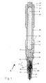
- Fig. 1 shows a fuel injection valve 4, which is intended for the intermittent injection of fuel into the combustion chamber of an internal combustion engine. It has an elongated, outer partially circular cylindrical and stepped housing 6, the central housing axis is denoted by 8.
- the housing 6 consists of a one-piece housing body 10, an intermediate plate 12 and a nozzle body 14. Die Intermediate plate 12 and the nozzle body 14 are held together with a trained as a union nut nut 16, which is threaded by a thread 16 'on the housing body 10, held together in a sealed manner against each other and pressed against an axial end face 18 of the housing body 10.
- a designed as a high pressure supply hole 20 high-pressure fuel inlet of the fuel injection valve 4 is connected in a known manner with a fuel supply, which supplies the fuel injection valve 4 fuel at very high pressure, for example, 1800 bar or higher.
- the high pressure supply bore 20 is located substantially closer to the nozzle body 14 than the upper end 24 of the housing body 10 and is made at an angle of 90 ° transverse to the housing axis 8 in the housing body 10.
- In the high pressure supply hole 20 opens one end of a longitudinal bore 22, which is also made in the housing body 10, the other end opens into the end face 18.
- An actuator assembly 26 is located laterally of the longitudinal bore 22 and offset from the housing axis 8.
- the nozzle body 14 contains a hydraulic control device 28 for a needle-shaped injection valve member 30.
- the fuel injection valve 4 is by means of a Clamp (not shown), which transmits on two shoulders 36 of the housing body 10 their clamping force in a known manner, held in the cylinder head of the internal combustion engine and sealed against the combustion chamber (not shown). In a region 38 above the shoulders 36, the outer wall of the housing body 10 is tapered over a certain length and can then be thicker again.
- the storage chamber 34 is relatively long and because of the taper in the area 38 above the shoulders 36, the inner diameter of the storage chamber 34 may not be very large for reasons of strength. In order to obtain a sufficient volume for a specific injection quantity, it is therefore advantageous if the storage chamber can extend as far as possible to the front, to the high-pressure supply hole 20.
- the storage chamber 34 is closed in a sealed manner by means of a pin 40 which is located in the housing body 10.
- a cylinder head end cap (not shown) encloses the housing body 10 in the region of an O-ring groove 42.
- the entire fuel injector 4 including storage chamber 34 is thus located below the cylinder head cover of the internal combustion engine and from the outside only the pin 40 and the upper end 24 are visible Nevertheless, thanks to the very compact arrangement of the functional elements of the fuel injection valve 4, it is possible to accommodate in the one-piece housing body 10 a storage chamber 34 that is sufficiently large and can be produced as a slim bore for most applications. With the dashed lines 44 and 46 above and below the tapered portion 38 is indicated how the volume of the storage chamber 34, if necessary, can be increased without the outer contour of the housing body 10th to have to change.
- the fuel injector 4 does not have a tapered portion 38 and is secured in the cylinder head of the internal combustion engine in a manner other than with a clamp. In these applications, the shoulders account for 36. Designed as a slim bore storage chamber 34 is still advantageous because many fuel injectors 4 have a slim outer contour of the housing body 10.
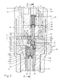
- Fig. 1 enlarged partial section of Fig. 2 shows the functional elements of the fuel injection valve 4 in more detail.
- the intermediate plate 12 is an oblique bore 48, which connects the longitudinal bore 22 with a passage 50 in the nozzle body 14, which in turn opens from the upper end surface 14 'of the nozzle body 14 in the high-pressure chamber 52 of the nozzle body 14.
- the needle-shaped injection valve member 30 which cooperates on the one hand with the injection valve seat 54 and on the other hand formed as a control piston 56 piston-like end portion, in the manner of a double-acting piston, in a cylinder forming a guide sleeve 58 in close Sliding fit of about 0.002-0.010 mm in the direction of the housing axis 8 is slidably guided.
- a closing spring 60 arranged concentrically around the injection valve member 30 is supported at one end by a support disk 62 and a support collar 64 in a known manner against a circumferential shoulder of the injection valve member 30 and acts upon this with a closing force directed toward the injection valve seat 54.
- the closing spring 60 is supported on a first end face 66 of the guide sleeve 58, which rests with its opposite second end face 68 on a control body 70.
- the pill-like shaped control body 70 is held by the force of the closing spring 60 and the fuel pressure at the lower end face 12a of the intermediate plate 12 in sealing engagement.
- the lower end face 12a forms a housing-fixed, sealing surface 11.
- the control body 70 is guided at its periphery by the wall of the high-pressure chamber 52 with a game of a few hundredths of a millimeter, thus radially non-sealing and is otherwise arranged loosely in the high-pressure chamber 52.
- the guide sleeve 58 Adjacent to the control body 70, the guide sleeve 58 has a radially projecting centering ring 74, by means of which it is held relative to the control body 70, also on the periphery of the wall of the high-pressure chamber 52 and radially non-sealing, centered.
- the guide sleeve 58 to its centering with respect to the nozzle body 14 on the first end face 66 projecting and the this side end portion of the closing spring 60 centering comprehensive guide ring 58 'on.
- annular gap is present between the guide sleeve 58 and the nozzle body 14.
- the guide sleeve 58 has in the vicinity of the first end face 66 radial passages 76 to connect said gap hydraulically with the lying between the guide sleeve 58 and the injection valve seat 54 part of the high-pressure chamber 52.
- the housing body 10 has a blind hole-like Aktuatorfactaus Principleung 78 emanating from the end face 18, in which a known electromagnetic actuator 80 (it could also be a piezoelectric actuator) is arranged to control the fuel injection valve 4.
- the actuator 80 and the actuator 80 associated with the functional elements are arranged on the Aktuatorachse 8 ', which is desachsiert to the housing axis 8.
- Adjacent to the end face 18 is in the Aktuatorabilityaus Principleung 78 a known magnetic circuit ring 84.
- a spacer ring is used in a spacer ring.
- a lower, planar surface 84 a of the magnetic lock ring 84 (or the spacer ring) is supported directly on the upper surface 12 b of the intermediate plate 12.
- a magnetic body 91 of the actuator 80 is a hollow cylinder-like magnetic head part 160, in which an actuator spring 94 is arranged.
- the actuator spring 94 is held biased by a guided in the upper region of the magnetic head portion 160 pin-like biasing member 162.
- the upper concave end 164 of the biasing member 162 which is located in a blind hole 168 of the housing body 10, protrudes in the transverse direction of a biasing screw 166 (see also at Fig. 4 and the associated part of the description).
- Return fuel which is relieved during each injection operation of the hydraulic control device 28 flows from the actuator 80 in unspecified passages and holes in the blind hole 168 and is then led away from the fuel injector 4 (see also Fig. 7 ).
- An O-ring 172 seals the space of the blind bore 168 toward the actuator receiving recess 78.
- a strand 174 is led from the winding 90 laterally through the magnetic head portion 160 and from here to a connector (see also Fig. 7 ).
- a plate spring 170 which is located between the Aktuatorfactaus Principleung 78 and the blind hole 168, on the one hand supported on the housing body 10. Innwannon the plate spring 170 is supported on the magnetic head part 160.
- the actuator assembly 26 is pressed against the top surface 12b of the intermediate plate 12 and stably biased held.
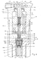
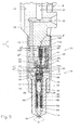
- Fig. 3 and Fig. 4 show the details of the actuator assembly 26 and the hydraulic control device 28 in FIG Fig. 2 once again enlarged scale.
- the cutting plane of Fig. 3 is the same as those of Fig. 2
- the cutting planes of Fig. 4 are perpendicular to the cutting plane of Fig. 3 and extend to the end face 14 'of the nozzle body 14 through the housing axis 8, above this end face 14' through the actuator axis 8 '(see section line A - A in FIG Fig. 3 ).
- the actuator 80 has an actuating shaft 86 cooperating with a pilot valve member 82 and a pawl-shaped closure member 96 for a pilot valve 92, to which a plate-like armature 88 is attached.
- the opening stroke H of the operating shaft 86 is smaller than the air gap L between the armature 88 and the magnetic body 91, since the operating shaft 86 in the lower part first has a tapered portion 102 extending below an integrally formed on the intermediate plate 12 stop 98 on the Side of the closure part 96, thickened again and forms a, acting as a counter-abutment, annular surface 104.
- the annular surface 104 bounded by striking the lower surface of the protruding stop 98 of the intermediate plate 12, the stroke H of the pilot valve member 82, thus a residual air gap between the armature 88 and the magnetic body 91, which is equal to L minus H, positively affects the turn-off of the electromagnetic actuator 80 in a known manner.
- the geometric shape of the projecting stop 98 and the installation of the pilot valve member 82 is conceptually the same as in the corresponding stop member of the international patent application WO 2005/080785 A1 , there referred to as a stop shoulder and in the Fig. 3 and 4 this application described in detail.
- the pilot valve 92 When de-energizing the winding 90, the pilot valve 92 is closed by means of the actuator spring 94.
- the closure member 96 is guided radially by a ring member 87 with play, which is fixedly connected as a separate part with the operating shaft 86, which can be realized for example by welding the two workpieces or by a press fit.
- the ring member 87 can be made in one piece with the operating shaft 86.
- an intermediate valve body 106 which is displaceable in the direction of the housing axis 8, is guided in the guide sleeve 58 with play and has a lower end face 106a.
- the intermediate valve body 106 extends to the housing axis 8 coaxial throttle passage 108 which extends between the lower and upper end face 106 a, 106 b of the intermediate valve body 106.
- a spring element 112 is arranged, which rests on the one hand on the intermediate valve body 106 and on the other hand on a bearing end face of the control piston 56.
- the spring element 112 surrounds a central projection of the control piston 56 and generates on the intermediate valve body 106, a force which is substantially smaller than the force exerted by the closing spring 60 force.
- With the upper end face 106b of the intermediate valve body 106 is located on a lower, serving as a sealing surface end face 70a of the control body 70 at.
- the control body 70 has a control passage 114, which is off-axis with respect to the housing axis 8 and coaxial with the actuator axis 8 ', and into which a throttle restriction 115 hydraulically connected to the high pressure chamber 52 opens.
- the control passage 114 has at its, in the upper end face 70 b of the control body 70 opening end, a throttle restriction 116.
- the control passage 114 is in hydraulic communication with the throttle passage 108 in the inter-valve body 106.
- the mode of operation of the fuel injection valve 4 is summarized as follows: when the actuator assembly 26 is energized, the hydraulic control device 28 responds. This causes the injector member 30 to move away from the injector seat 54, thereby flowing fuel under high pressure from the storage chamber 34 via the bore 32 and from the high pressure supply bore 20 through the longitudinal bore 22 to the nozzle spray ports 54 'and injection commences. If the actuator assembly 26 is de-energized, the injection valve member 30 is moved in the direction of the injection valve seat 54 via the hydraulic control device 28 until the injection process is interrupted.
- WO 2005/080785 A1 describes a kind of fuel injector in detail.
- the intermediate plate 12 has a bore 122 with a collar 122 ', in which a centering pin 124 is positioned, which further protrudes into a blind hole 126 of the control body 70 introduced from the upper end side 70b and aligns this control body 70.
- Means for aligning the circumferential position of the control body 70 relative to the actuator assembly 26 is necessary because of the desaxial arrangement of the control passage 114 and the throttle restriction 116, which together with the actuator assembly 26 must be substantially aligned with the actuator axis 8 '.
- the collar 122 ' defines the axial Position of the centering pin 124 upwards with some play firmly.
- the housing body 10, the intermediate plate 12, and the nozzle body 14 are also positioned relative to each other in a known manner (not shown) to ensure alignment of the longitudinal bore 22, the oblique bore 48, and the passage 50.
- the means for aligning the control body 70 at its periphery and engage in the upper end of the wall of the high pressure chamber 52 of the nozzle body 14 a are the means for aligning the control body 70 at its periphery and engage in the upper end of the wall of the high pressure chamber 52 of the nozzle body 14 a.
- These means can be represented, for example, by asymmetrical shaping of the control body 70 in this area, with appropriate adaptation of the shape of the wall of the nozzle body 14, for example by a bulge at a favorable location of the control body 70 with a corresponding indentation of the wall of the nozzle body 14.
- the shaping can also be an additional radially on the circumference of the high-pressure chamber 52 introduced part, analogous to the centering pin 124 may be used.
- a piezoactuator which is known to be radially slimmer
- the outer diameter in the region of the clamping nut 16 can be made very compact and small thanks to the advantages mentioned above. Further, with a piezo actuator serving as a stop shoulder, projecting stop 98 of the intermediate plate 12 omitted.
- This alternative design can therefore be used successfully for large diesel engines, such as ships, locomotives and construction machinery, as well as for smaller engines in the truck sector or below.
- Fig. 4 also shows how the biasing member 162 and the biasing screw 166 can bias the actuator spring 94.
- a tapered portion 166 'of the preload screw 166 engages the upper concave end 164 of the biasing member 162, which has an inclined contact surface.
- the conical section 166 ' can by moving the preload screw 166 in the housing body 10, by means of the thread 176, clockwise or counterclockwise, the biasing member 162 more or less far down to adjust the biasing force of the actuator 94. If the desired value is set, the preload screw 166 can be blocked with a lock nut 178. With a nose 180 of the biasing screw 166, this can additionally be performed in the housing body 10 and supported therein. This external adjustment is very convenient.
- Fig. 5 shows a partial section of a first alternative variant of the inventive fuel injection valve.
- a cylindrical element 13 forms a separate workpiece, which is not integral with the housing body 10.
- This cylindrical element 13 comprises a bottom part 13 ', which of the Fig. 1-4 her known intermediate plate 12 corresponds, and an overlying portion in which desachsiert the Aktuatorageaus Principleung 78 'is received with the actuator assembly 26.
- the clamping nut 16 is formed correspondingly longer and the thread 16 'is located above, as in Fig. 2 shown.
- the assembly of the actuator assembly 26 is facilitated.
- the bottom part 13 ' may also be formed as a separate part, which is in Fig. 5 is shown with a dashed line 13 ".
- the cylindrical element 13 is fixed by means of the clamping nut 16 fixed to the housing between the housing body 10 and nozzle body 14.
- the magnetic head portion 160 ' which is located above the magnetic body 91, includes for biasing the actuator spring 94, a biasing member 162' of a given thickness.
- the biasing force of the actuator spring 94 when assembled fuel injector from the outside is no longer changeable.
- FIG. 5 an alternative embodiment of the stop for the pilot valve member 82, which as a flat Stop disc 97 is formed and is disposed between the magnetic lock ring 84 and the bottom 78 "of the Aktuatorfactaus Principleung 78 'forming the bottom part 13', in an analogous manner as the intermediate plate 12 ( Fig. 1 to 4 ), on its underside, the housing-fixed sealing surface (11) together with the upper end face 70b of the control body 70, which sealingly separates the high-pressure chamber 52 to the Aktuatorareaaus Principleung 78 'down.
- the operating shaft 86 of the pilot valve member 82 can be pushed laterally through the stopper plate 97 before these two components are installed in the cylindrical member 13.
- a stop 99 is the lower flat surface of the stopper plate 97.
- This simple design of the stopper as a flat stop plate 97 can of course also as an alternative to the solution according to the Fig. 1 to 4 be used.
- the intermediate plate 12 has in this case no protruding stop 98 more.
- the dashed line 13 '' indicates a further alternative embodiment, in which case the cylindrical element 13 extends from the nozzle body 14 to the line 13 '' '.
- the housing body 10 abuts the cylindrical element 13 and the clamping nut 16 is correspondingly shorter.
- the housing body 10 has a blind hole-like recess for the actuator spring 94; Figuratively speaking, the magnetic head part 160 'is formed on the housing body 10.
- Fig. 6 shows a partial section of a second alternative variant of the inventive fuel injection valve.
- the high-pressure chamber 152 of a hollow-cylinder-like nozzle body holding part 130 extends with a sufficiently large inner diameter 152a up to a shoulder 128.
- the nozzle body 132 is manufactured as a separate cup-like member of a particularly wear-resistant material from the nozzle body holding member 130 and seals with a conical surface 134 together with a mating tapered surface of the nozzle body holding member 130 the high-pressure chamber 152 against the engine combustion chamber (not shown) from.
- the nozzle body 132 executed with an integrally molded collar 136.
- the cylindrical circumference of the collar 136 has a clearance of a few hundredths of a millimeter with the inner diameter 152a and supports with its surface 136a on a shoulder 128 of the nozzle body holding part 130 from. This construction has a better compressive strength than that in the WO 2005/008059 A1 revealed.
- the injection valve member 138 with a sufficient distance above the collar 136 has a guide 140 together with the inner diameter 152a.
- This guide 140 may be short and has at least one passage 142, for example, three passages 142, which are made by 120 ° offset on the circumference of the guide 140.
- the clearance between the guide 140 and the inner diameter 152a may be between 0.002 and 0.05 mm, substantially more than with conventional injectors, since the guide 140 is located near the injection valve seat 54.
- the support plate 62 is supported directly on the top of the guide 140 from.
- the guide sleeve 143 is below, unlike in the Fig. 1 - 2 , no longer in the nozzle body holding part 130, but forms an annular passage 144.
- the radial passages 76 of the guide sleeve 58 (see Fig. 2 ) superfluous.
- the passage cross sections of the passages 142 and 144 are such that during an injection process, the fuel can flow without significant pressure loss from the passage 50 to the injection valve seat 54.
- the injection valve member 138 is guided by an inner guide of the collar 136 of the nozzle body 132 that has been extended for this purpose.
- the guide 140 of the injection valve member 138 with the nozzle body holding part 130 is omitted in this case.
- Fig. 7 is a longitudinal section of the inventive fuel injection valve 4 of Fig. 1 in a cutting plane, like at Fig. 4 perpendicular to the cutting plane of Fig. 1 is.
- Designated at 146 is the bore for returning the fuel released during the injection process and at 148 a bore in the housing body 10, in which the strands 174 of the winding 90 are led to an external electrical connection 150 for these strands 174 attached to the housing body 10.
- Fig. 8 shows in longitudinal section a partial section of another inventive fuel injection valve 200 with a spacer sleeve 202, in which a part of the injection valve member 204 and the functional elements of the hydraulic control device 28 are installed.
- This construction is advantageous if the front part 208 of the nozzle body 206 is so slender that only just the guide 210 of the injection valve member 204 has room in it.
- a clamping nut 212 biases the nozzle body 206 to the spacer sleeve 202 and this to the housing body 214, wherein these elements have the known sealing surfaces to seal the high pressure.
- the high pressure fuel passes through the longitudinal bore 216 in the housing body 214 and through a longitudinal bore 218 in the spacer sleeve 202 to the nozzle body 206.
- Centric in the spacer sleeve 202 is a high pressure chamber 220, wherein the support plate 62, the closing spring 60, the guide sleeve 58 and the hydraulic Control device 28 together with an upper part of the injection valve member 204 are located.
- the spacer sleeve 202 is closed except for three holes 224, 226 and 228.
- the control body 230 is supported on a conical shoulder 232, which forms the housing-fixed, sealing surface 11, and thus seals the high-pressure chamber 220 from.
- a flat shoulder which is perpendicular to the housing axis 8, could be used to support the control body 230 and seal the high-pressure chamber 220.
- the control body 230 otherwise guided radially non-sealing, is loosely in the high-pressure chamber 220 and axially positioned by the shoulder 232.
- a circular cylindrical closure member 234 is guided in the bore 224.
- the dashed line shown Bore 228 is located at a position past bores 224 and 228 and serves to discharge the fuel released during an injection from the outlet side of the pilot valve 92 into the stop plate 238 and from there in a manner not shown in detail away from the fuel injector 200 Alternatively, this hydraulic connection 240 could be formed by a suitable recess in the control body 230 and the control body 230 could then be supported with the remaining part of an upper flat surface on an inner planar end surface of the spacer sleeve 202 and Seal the high-pressure chamber 220.
- the centering pin 236 centers with respect to the spacer sleeve 202 both the control body 230 and the stop plate 238, which directly adjoins the upper end face 202a with its surface 238a and abuts with its surface 238b against the lower surface 84a of the magnetic closure ring 84.
- the front part of the operating shaft 86 is located inside the stopper plate 238, and the stopper for limiting the stroke of the pilot valve member is the same as in the corresponding element of the international patent application WO 2005/080785 A1 , Of course, these details may alternatively be the same as in the fuel injection valve 4.
- the high pressure supply bore is disposed axially in the pin 40 together with the associated high pressure port.
- the pin is Pin 40 extended upward to a storage chamber and hydraulically connected to a bore in the region of the thread of the pin 40 with the longitudinal bore 22 or 216.
Landscapes
- Engineering & Computer Science (AREA)
- Chemical & Material Sciences (AREA)
- Combustion & Propulsion (AREA)
- Mechanical Engineering (AREA)
- General Engineering & Computer Science (AREA)
- Physics & Mathematics (AREA)
- Fluid Mechanics (AREA)
- Manufacturing & Machinery (AREA)
- Fuel-Injection Apparatus (AREA)
Applications Claiming Priority (2)
| Application Number | Priority Date | Filing Date | Title |
|---|---|---|---|
| CH16472006 | 2006-10-16 | ||
| EP07816189A EP2092186B1 (fr) | 2006-10-16 | 2007-10-15 | Soupape d'injection de carburant pour moteurs à combustion interne |
Related Parent Applications (2)
| Application Number | Title | Priority Date | Filing Date |
|---|---|---|---|
| EP07816189.0 Division | 2007-10-15 | ||
| EP07816189A Division EP2092186B1 (fr) | 2006-10-16 | 2007-10-15 | Soupape d'injection de carburant pour moteurs à combustion interne |
Publications (2)
| Publication Number | Publication Date |
|---|---|
| EP2175124A1 true EP2175124A1 (fr) | 2010-04-14 |
| EP2175124B1 EP2175124B1 (fr) | 2014-09-24 |
Family
ID=39203205
Family Applications (2)
| Application Number | Title | Priority Date | Filing Date |
|---|---|---|---|
| EP07816189A Active EP2092186B1 (fr) | 2006-10-16 | 2007-10-15 | Soupape d'injection de carburant pour moteurs à combustion interne |
| EP10000079.3A Active EP2175124B1 (fr) | 2006-10-16 | 2007-10-15 | Injecteur de carburant pour moteurs à combustion interne |
Family Applications Before (1)
| Application Number | Title | Priority Date | Filing Date |
|---|---|---|---|
| EP07816189A Active EP2092186B1 (fr) | 2006-10-16 | 2007-10-15 | Soupape d'injection de carburant pour moteurs à combustion interne |
Country Status (8)
| Country | Link |
|---|---|
| US (1) | US7891586B2 (fr) |
| EP (2) | EP2092186B1 (fr) |
| CN (1) | CN101542103B (fr) |
| AT (1) | ATE455952T1 (fr) |
| BR (1) | BRPI0717642A2 (fr) |
| DE (1) | DE502007002707D1 (fr) |
| WO (1) | WO2008046238A2 (fr) |
| ZA (1) | ZA200902459B (fr) |
Families Citing this family (14)
| Publication number | Priority date | Publication date | Assignee | Title |
|---|---|---|---|---|
| DE102009000285A1 (de) * | 2009-01-19 | 2010-07-22 | Robert Bosch Gmbh | Kraftstoff-Injektor sowie Brennkraftmaschine mit Kraftstoff-Injektor |
| JP5240181B2 (ja) * | 2009-12-24 | 2013-07-17 | 株式会社デンソー | 燃料噴射装置 |
| CH704454A1 (de) * | 2011-02-08 | 2012-08-15 | Liebherr Machines Bulle Sa | Einspritzvorrichtung für ein Fluid. |
| CN102418635A (zh) * | 2011-12-31 | 2012-04-18 | 中国兵器工业集团第七○研究所 | 一种电控喷油器 |
| CN104093968B (zh) | 2012-02-07 | 2016-10-12 | 甘瑟-许德罗玛格股份公司 | 燃料喷射阀和用于喷射燃料的装置 |
| DE102012208075A1 (de) * | 2012-05-15 | 2013-11-21 | Man Diesel & Turbo Se | Injektor für eine Kraftstoffversorgungsanlage einer Brennkraftmaschine sowie Kraftstoffversorgungsanlage |
| EP2674608B1 (fr) * | 2012-06-13 | 2015-08-12 | Delphi International Operations Luxembourg S.à r.l. | Injecteur à carburant |
| KR102098354B1 (ko) | 2013-03-01 | 2020-04-09 | 간제르-히드로막 아게 | 내연 기관의 연소실에 연료를 분사하기 위한 장치 |
| DE102013013234A1 (de) * | 2013-08-08 | 2015-02-12 | Man Diesel & Turbo Se | Injektor für eine Kraftstoffversorgungsanlage einer Brennkraftmaschine sowie Kraftstoffversorgungsanlage |
| JP6080087B2 (ja) * | 2014-02-28 | 2017-02-15 | 株式会社デンソー | 燃料噴射弁 |
| CH710127A1 (de) * | 2014-09-17 | 2016-03-31 | Ganser Crs Ag | Brennstoffeinspritzventil für Verbrennungskraftmaschinen. |
| FR3027068B1 (fr) * | 2014-10-08 | 2019-09-13 | Delphi Technologies Ip Limited | Injecteur de carburant |
| FR3038662B1 (fr) * | 2015-07-09 | 2019-08-09 | Delphi Technologies Ip Limited | Injecteur de carburant avec tarage exterieur du ressort de bobine |
| DE102015223043A1 (de) * | 2015-11-23 | 2017-05-24 | Robert Bosch Gmbh | Kraftstoff-Injektor |
Citations (7)
| Publication number | Priority date | Publication date | Assignee | Title |
|---|---|---|---|---|
| DE3119050A1 (de) | 1981-05-05 | 1982-11-18 | Gebrüder Sulzer AG, 8401 Winterthur | "brennstoffeinspritzvorrichtung mit elektromagnetisch betaetigtem umschaltventil" |
| DE10031698A1 (de) | 2000-06-29 | 2002-01-17 | Mtu Friedrichshafen Gmbh | Kraftstoffinjektor für eine Brennkraftmaschine |
| WO2002052145A1 (fr) * | 2000-12-23 | 2002-07-04 | Robert Bosch Gmbh | Electrovalve pour la commande d'une soupape d'injection d'un moteur a combustion interne |
| WO2005008059A1 (fr) | 2003-07-17 | 2005-01-27 | Ganser-Hydromag Ag | Soupape d'injection de carburant pour moteurs a combustion interne |
| WO2005080785A1 (fr) | 2004-02-25 | 2005-09-01 | Ganser-Hydromag Ag | Soupape d'injection de carburant pour moteurs a combustion interne |
| EP1600627A1 (fr) * | 2004-05-15 | 2005-11-30 | L'orange Gmbh | Soupape de régulation |
| WO2006058444A1 (fr) * | 2004-12-03 | 2006-06-08 | Ganser-Hydromag Ag | Soupape d'injection de combustible a multiplication de pression |
Family Cites Families (12)
| Publication number | Priority date | Publication date | Assignee | Title |
|---|---|---|---|---|
| DE3681711D1 (de) * | 1985-12-02 | 1991-10-31 | Marco Alfredo Ganser | Kraftstoffeinspritzanlage fuer brennkraftmaschinen. |
| GB9606803D0 (en) * | 1996-03-30 | 1996-06-05 | Lucas Ind Plc | Injection nozzle |
| IT1293433B1 (it) * | 1997-07-11 | 1999-03-01 | Elasis Sistema Ricerca Fiat | Valvola di dosaggio registrabile per un iniettore di combustibile per motori a combustione interna, e relativo metodo di registrazione. |
| DE59903599D1 (de) * | 1998-11-10 | 2003-01-09 | Ganser Hydromag Ag Zuerich | Brennstoffeinspritzventil für verbrennungskraftmaschinen |
| DE10118053A1 (de) * | 2001-04-11 | 2002-10-24 | Bosch Gmbh Robert | Ventil zum Steuern von Flüssigkeiten |
| DE10131953A1 (de) * | 2001-07-02 | 2003-01-23 | Siemens Ag | Steuermodul für einen Injektor eines Speichereinspritzsystems |
| JP2003113761A (ja) * | 2001-08-01 | 2003-04-18 | Denso Corp | 燃料噴射弁 |
| DE10139623A1 (de) * | 2001-08-11 | 2003-02-27 | Bosch Gmbh Robert | Einspritzanordnung für ein Kraftstoff-Speichereinspritzsystem |
| DE10201470A1 (de) * | 2002-01-16 | 2003-08-07 | Bosch Gmbh Robert | Doppeltschaltendes Ventil für Kraftstoffeinspritzanlagen |
| DE102005026514B4 (de) * | 2005-02-18 | 2008-12-24 | Robert Bosch Gmbh | Einspritzdüse |
| ATE488690T1 (de) * | 2005-07-18 | 2010-12-15 | Ganser Hydromag | Speichereinspritzsystem für brennkraftmaschine |
| DE102005035347B3 (de) * | 2005-07-28 | 2006-08-10 | L'orange Gmbh | Kraftstoffinjektor |
-
2007
- 2007-10-15 EP EP07816189A patent/EP2092186B1/fr active Active
- 2007-10-15 EP EP10000079.3A patent/EP2175124B1/fr active Active
- 2007-10-15 US US12/445,730 patent/US7891586B2/en active Active
- 2007-10-15 WO PCT/CH2007/000506 patent/WO2008046238A2/fr active Application Filing
- 2007-10-15 AT AT07816189T patent/ATE455952T1/de active
- 2007-10-15 ZA ZA200902459A patent/ZA200902459B/xx unknown
- 2007-10-15 CN CN2007800429354A patent/CN101542103B/zh active Active
- 2007-10-15 DE DE502007002707T patent/DE502007002707D1/de active Active
- 2007-10-15 BR BRPI0717642-2A2A patent/BRPI0717642A2/pt not_active IP Right Cessation
Patent Citations (7)
| Publication number | Priority date | Publication date | Assignee | Title |
|---|---|---|---|---|
| DE3119050A1 (de) | 1981-05-05 | 1982-11-18 | Gebrüder Sulzer AG, 8401 Winterthur | "brennstoffeinspritzvorrichtung mit elektromagnetisch betaetigtem umschaltventil" |
| DE10031698A1 (de) | 2000-06-29 | 2002-01-17 | Mtu Friedrichshafen Gmbh | Kraftstoffinjektor für eine Brennkraftmaschine |
| WO2002052145A1 (fr) * | 2000-12-23 | 2002-07-04 | Robert Bosch Gmbh | Electrovalve pour la commande d'une soupape d'injection d'un moteur a combustion interne |
| WO2005008059A1 (fr) | 2003-07-17 | 2005-01-27 | Ganser-Hydromag Ag | Soupape d'injection de carburant pour moteurs a combustion interne |
| WO2005080785A1 (fr) | 2004-02-25 | 2005-09-01 | Ganser-Hydromag Ag | Soupape d'injection de carburant pour moteurs a combustion interne |
| EP1600627A1 (fr) * | 2004-05-15 | 2005-11-30 | L'orange Gmbh | Soupape de régulation |
| WO2006058444A1 (fr) * | 2004-12-03 | 2006-06-08 | Ganser-Hydromag Ag | Soupape d'injection de combustible a multiplication de pression |
Also Published As
| Publication number | Publication date |
|---|---|
| US20100294243A1 (en) | 2010-11-25 |
| WO2008046238A3 (fr) | 2008-07-03 |
| ATE455952T1 (de) | 2010-02-15 |
| ZA200902459B (en) | 2010-07-28 |
| EP2175124B1 (fr) | 2014-09-24 |
| CN101542103A (zh) | 2009-09-23 |
| EP2092186A2 (fr) | 2009-08-26 |
| WO2008046238A2 (fr) | 2008-04-24 |
| CN101542103B (zh) | 2011-12-14 |
| US7891586B2 (en) | 2011-02-22 |
| EP2092186B1 (fr) | 2010-01-20 |
| DE502007002707D1 (de) | 2010-03-11 |
| BRPI0717642A2 (pt) | 2013-11-12 |
Similar Documents
| Publication | Publication Date | Title |
|---|---|---|
| EP2092186B1 (fr) | Soupape d'injection de carburant pour moteurs à combustion interne | |
| DE602006000409T2 (de) | Kraftstoffinjektor mit elektromagnetischem Aktor | |
| EP2812559B1 (fr) | Injecteur de carburant et dispositif d'injection de carburant | |
| EP1266135B1 (fr) | Electrovanne destinee a commander la soupape d'injection d'un moteur a combustion interne | |
| EP2394049B1 (fr) | Injecteur de carburant pour moteurs à combustion interne | |
| EP3194757B1 (fr) | Injecteur de carburant pour moteurs à combustion interne | |
| EP1989436B1 (fr) | Dispositif d'injection de carburant pour moteur a combustion interne | |
| EP1718862B1 (fr) | Soupape d'injection de carburant pour moteurs a combustion interne | |
| EP1869311B1 (fr) | Injecteur de carburant | |
| EP1431567A2 (fr) | Soupape d'injection de combustible pour moteurs à combustion interne | |
| DE19709794A1 (de) | Ventil zum Steuern von Flüssigkeiten | |
| DE102007047426A1 (de) | Injektor mit Piezoaktor | |
| EP2961977A1 (fr) | Dispositif permettant d'injecter un carburant dans la chambre de combustion d'un moteur à combustion interne | |
| DE4341545A1 (de) | Kraftstoffeinspritzeinrichtung für Brennkraftmaschinen | |
| WO2020260285A1 (fr) | Soupape d'injection de carburant pour des moteurs à combustion interne | |
| DE2642177C2 (de) | Elektrisch gesteuertes Kraftstoffeinspritzsystem für Dieselbrennkraftmaschinen | |
| WO2008049699A1 (fr) | Injecteur de carburant | |
| DE3933331A1 (de) | Kraftstoffeinspritzventil fuer kraftstoffeinspritzanlagen von brennkraftmaschinen | |
| EP0990792A2 (fr) | Système d'injection de carburant de type Common-Rail | |
| EP1278952B1 (fr) | Soupape d'injection de carburant | |
| DE19940300A1 (de) | Steuerventil für einen Injektor | |
| WO2008049668A1 (fr) | Injecteur d'injection de carburant dans des chambres de combustion de moteurs à combustion interne | |
| DE10121340A1 (de) | Common-Rail-Injektor | |
| DE10132450A1 (de) | Kraftstoffeinspritzventil für Brennkraftmaschinen | |
| DE102004051406B4 (de) | Kraftstoffinjektor mit einer im Düsenkörper geführten Hohlnadel einer Registerdüse |
Legal Events
| Date | Code | Title | Description |
|---|---|---|---|
| PUAI | Public reference made under article 153(3) epc to a published international application that has entered the european phase |
Free format text: ORIGINAL CODE: 0009012 |
|
| AC | Divisional application: reference to earlier application |
Ref document number: 2092186 Country of ref document: EP Kind code of ref document: P |
|
| AK | Designated contracting states |
Kind code of ref document: A1 Designated state(s): AT BE BG CH CY CZ DE DK EE ES FI FR GB GR HU IE IS IT LI LT LU LV MC MT NL PL PT RO SE SI SK TR |
|
| 17P | Request for examination filed |
Effective date: 20100920 |
|
| RBV | Designated contracting states (corrected) |
Designated state(s): AT CH DE GB LI |
|
| 17Q | First examination report despatched |
Effective date: 20101206 |
|
| RIC1 | Information provided on ipc code assigned before grant |
Ipc: F02M 61/10 20060101ALI20140212BHEP Ipc: F02M 47/02 20060101AFI20140212BHEP Ipc: F02M 61/16 20060101ALI20140212BHEP Ipc: F02M 61/20 20060101ALI20140212BHEP Ipc: F02M 51/06 20060101ALN20140212BHEP Ipc: F02M 63/00 20060101ALI20140212BHEP |
|
| GRAP | Despatch of communication of intention to grant a patent |
Free format text: ORIGINAL CODE: EPIDOSNIGR1 |
|
| INTG | Intention to grant announced |
Effective date: 20140505 |
|
| GRAS | Grant fee paid |
Free format text: ORIGINAL CODE: EPIDOSNIGR3 |
|
| GRAA | (expected) grant |
Free format text: ORIGINAL CODE: 0009210 |
|
| AC | Divisional application: reference to earlier application |
Ref document number: 2092186 Country of ref document: EP Kind code of ref document: P |
|
| AK | Designated contracting states |
Kind code of ref document: B1 Designated state(s): AT CH DE GB LI |
|
| REG | Reference to a national code |
Ref country code: GB Ref legal event code: FG4D Free format text: NOT ENGLISH |
|
| REG | Reference to a national code |
Ref country code: CH Ref legal event code: EP |
|
| REG | Reference to a national code |
Ref country code: AT Ref legal event code: REF Ref document number: 688768 Country of ref document: AT Kind code of ref document: T Effective date: 20141015 Ref country code: CH Ref legal event code: NV Representative=s name: PATENTANWAELTE SCHAAD, BALASS, MENZL AND PARTN, CH |
|
| REG | Reference to a national code |
Ref country code: DE Ref legal event code: R096 Ref document number: 502007013484 Country of ref document: DE Effective date: 20141106 |
|
| REG | Reference to a national code |
Ref country code: DE Ref legal event code: R097 Ref document number: 502007013484 Country of ref document: DE |
|
| PLBE | No opposition filed within time limit |
Free format text: ORIGINAL CODE: 0009261 |
|
| STAA | Information on the status of an ep patent application or granted ep patent |
Free format text: STATUS: NO OPPOSITION FILED WITHIN TIME LIMIT |
|
| 26N | No opposition filed |
Effective date: 20150625 |
|
| P01 | Opt-out of the competence of the unified patent court (upc) registered |
Effective date: 20230510 |
|
| PGFP | Annual fee paid to national office [announced via postgrant information from national office to epo] |
Ref country code: GB Payment date: 20231020 Year of fee payment: 17 |
|
| PGFP | Annual fee paid to national office [announced via postgrant information from national office to epo] |
Ref country code: DE Payment date: 20231020 Year of fee payment: 17 Ref country code: CH Payment date: 20231102 Year of fee payment: 17 Ref country code: AT Payment date: 20231020 Year of fee payment: 17 |