EP2175121A1 - Verfahren zur Erkennung einer anormalen Verbrennung für Verbrennungsmotoren - Google Patents
Verfahren zur Erkennung einer anormalen Verbrennung für Verbrennungsmotoren Download PDFInfo
- Publication number
- EP2175121A1 EP2175121A1 EP09290720A EP09290720A EP2175121A1 EP 2175121 A1 EP2175121 A1 EP 2175121A1 EP 09290720 A EP09290720 A EP 09290720A EP 09290720 A EP09290720 A EP 09290720A EP 2175121 A1 EP2175121 A1 EP 2175121A1
- Authority
- EP
- European Patent Office
- Prior art keywords
- combustion
- values
- distribution
- threshold
- engine
- Prior art date
- Legal status (The legal status is an assumption and is not a legal conclusion. Google has not performed a legal analysis and makes no representation as to the accuracy of the status listed.)
- Withdrawn
Links
Images


Classifications
-
- F—MECHANICAL ENGINEERING; LIGHTING; HEATING; WEAPONS; BLASTING
- F02—COMBUSTION ENGINES; HOT-GAS OR COMBUSTION-PRODUCT ENGINE PLANTS
- F02D—CONTROLLING COMBUSTION ENGINES
- F02D35/00—Controlling engines, dependent on conditions exterior or interior to engines, not otherwise provided for
- F02D35/02—Controlling engines, dependent on conditions exterior or interior to engines, not otherwise provided for on interior conditions
- F02D35/023—Controlling engines, dependent on conditions exterior or interior to engines, not otherwise provided for on interior conditions by determining the cylinder pressure
-
- F—MECHANICAL ENGINEERING; LIGHTING; HEATING; WEAPONS; BLASTING
- F02—COMBUSTION ENGINES; HOT-GAS OR COMBUSTION-PRODUCT ENGINE PLANTS
- F02D—CONTROLLING COMBUSTION ENGINES
- F02D35/00—Controlling engines, dependent on conditions exterior or interior to engines, not otherwise provided for
- F02D35/02—Controlling engines, dependent on conditions exterior or interior to engines, not otherwise provided for on interior conditions
- F02D35/027—Controlling engines, dependent on conditions exterior or interior to engines, not otherwise provided for on interior conditions using knock sensors
-
- F—MECHANICAL ENGINEERING; LIGHTING; HEATING; WEAPONS; BLASTING
- F02—COMBUSTION ENGINES; HOT-GAS OR COMBUSTION-PRODUCT ENGINE PLANTS
- F02D—CONTROLLING COMBUSTION ENGINES
- F02D35/00—Controlling engines, dependent on conditions exterior or interior to engines, not otherwise provided for
- F02D35/02—Controlling engines, dependent on conditions exterior or interior to engines, not otherwise provided for on interior conditions
- F02D35/028—Controlling engines, dependent on conditions exterior or interior to engines, not otherwise provided for on interior conditions by determining the combustion timing or phasing
-
- G—PHYSICS
- G01—MEASURING; TESTING
- G01M—TESTING STATIC OR DYNAMIC BALANCE OF MACHINES OR STRUCTURES; TESTING OF STRUCTURES OR APPARATUS, NOT OTHERWISE PROVIDED FOR
- G01M15/00—Testing of engines
- G01M15/04—Testing internal-combustion engines
- G01M15/08—Testing internal-combustion engines by monitoring pressure in cylinders
-
- F—MECHANICAL ENGINEERING; LIGHTING; HEATING; WEAPONS; BLASTING
- F02—COMBUSTION ENGINES; HOT-GAS OR COMBUSTION-PRODUCT ENGINE PLANTS
- F02D—CONTROLLING COMBUSTION ENGINES
- F02D19/00—Controlling engines characterised by their use of non-liquid fuels, pluralities of fuels, or non-fuel substances added to the combustible mixtures
- F02D19/12—Controlling engines characterised by their use of non-liquid fuels, pluralities of fuels, or non-fuel substances added to the combustible mixtures peculiar to engines working with non-fuel substances or with anti-knock agents, e.g. with anti-knock fuel
-
- F—MECHANICAL ENGINEERING; LIGHTING; HEATING; WEAPONS; BLASTING
- F02—COMBUSTION ENGINES; HOT-GAS OR COMBUSTION-PRODUCT ENGINE PLANTS
- F02D—CONTROLLING COMBUSTION ENGINES
- F02D41/00—Electrical control of supply of combustible mixture or its constituents
- F02D41/24—Electrical control of supply of combustible mixture or its constituents characterised by the use of digital means
- F02D41/26—Electrical control of supply of combustible mixture or its constituents characterised by the use of digital means using computer, e.g. microprocessor
- F02D41/28—Interface circuits
- F02D2041/286—Interface circuits comprising means for signal processing
-
- F—MECHANICAL ENGINEERING; LIGHTING; HEATING; WEAPONS; BLASTING
- F02—COMBUSTION ENGINES; HOT-GAS OR COMBUSTION-PRODUCT ENGINE PLANTS
- F02D—CONTROLLING COMBUSTION ENGINES
- F02D41/00—Electrical control of supply of combustible mixture or its constituents
- F02D41/0002—Controlling intake air
-
- F—MECHANICAL ENGINEERING; LIGHTING; HEATING; WEAPONS; BLASTING
- F02—COMBUSTION ENGINES; HOT-GAS OR COMBUSTION-PRODUCT ENGINE PLANTS
- F02D—CONTROLLING COMBUSTION ENGINES
- F02D41/00—Electrical control of supply of combustible mixture or its constituents
- F02D41/0025—Controlling engines characterised by use of non-liquid fuels, pluralities of fuels, or non-fuel substances added to the combustible mixtures
-
- F—MECHANICAL ENGINEERING; LIGHTING; HEATING; WEAPONS; BLASTING
- F02—COMBUSTION ENGINES; HOT-GAS OR COMBUSTION-PRODUCT ENGINE PLANTS
- F02D—CONTROLLING COMBUSTION ENGINES
- F02D41/00—Electrical control of supply of combustible mixture or its constituents
- F02D41/30—Controlling fuel injection
- F02D41/38—Controlling fuel injection of the high pressure type
- F02D41/40—Controlling fuel injection of the high pressure type with means for controlling injection timing or duration
- F02D41/402—Multiple injections
-
- F—MECHANICAL ENGINEERING; LIGHTING; HEATING; WEAPONS; BLASTING
- F02—COMBUSTION ENGINES; HOT-GAS OR COMBUSTION-PRODUCT ENGINE PLANTS
- F02M—SUPPLYING COMBUSTION ENGINES IN GENERAL WITH COMBUSTIBLE MIXTURES OR CONSTITUENTS THEREOF
- F02M26/00—Engine-pertinent apparatus for adding exhaust gases to combustion-air, main fuel or fuel-air mixture, e.g. by exhaust gas recirculation [EGR] systems
- F02M26/13—Arrangement or layout of EGR passages, e.g. in relation to specific engine parts or for incorporation of accessories
- F02M26/17—Arrangement or layout of EGR passages, e.g. in relation to specific engine parts or for incorporation of accessories in relation to the intake system
- F02M26/20—Feeding recirculated exhaust gases directly into the combustion chambers or into the intake runners
Definitions
- the present invention relates to the field of controlling the combustion phase of an internal combustion engine.
- the present invention relates to a method for detecting an abnormal combustion of the pre-ignition type at low speed and at high load, in a combustion chamber of such an engine.
- This type of engine comprises at least one cylinder having a combustion chamber defined by the inner side wall of the cylinder, the top of the piston which slides in this cylinder and the cylinder head.
- a fuel mixture is enclosed in this combustion chamber and undergoes a compression step, then a combustion step under the effect of a controlled ignition, by a candle.
- the first combustion is the result of the propagation of the combustion of a compressed fuel mixture during a preliminary stage of compression of the engine. This combustion propagates normally according to a flame front from the spark generated at the candle, and does not risk damaging the engine.
- Another type of combustion is a knocking combustion, which results from undesirable self-ignition in the combustion chamber.
- the spark plug is actuated to allow ignition of this fuel mixture.
- This mechanism called rattling, leads to a local increase in pressure and temperature and can cause, in case of repetitions, destructive effects on the engine and mainly at the piston.
- Another type of combustion is an abnormal combustion due to a pre-ignition of the fuel mixture before the spark ignites ignition of the fuel mixture present in the combustion chamber.
- This abnormal combustion affects the engines that are the result of a "miniaturization” operation, better known as “downsizing”.
- This operation aims to reduce the size and / or the engine displacement while maintaining the same power and / or the same torque as conventional engines.
- this type of engine is mainly gasoline type and is highly supercharged.
- This abnormal combustion is carried out at high loads, and generally at low operating speeds of the engine, when the timing of the combustion of the fuel mixture can not be optimum because of the rattling.
- an abnormal combustion start can occur, sporadically or continuously, well before the moment when ignition of the fuel mixture by the candle is achieved .
- This combustion is characterized by a first phase of flame propagation that is wedged too early compared to that of a conventional combustion. This propagation phase can be interrupted by a self-ignition that will affect a large part of the fuel mixture present in the combustion chamber, much larger than in the case of rattling.
- pre-ignition In the case where this abnormal combustion occurs repeatedly, engine-cycle engine-cycle, and is carried out from a hot spot of the cylinder for example, it is called “pre-ignition”. If this combustion occurs violently, randomly and sporadically, it is called “snapping” or “rumble” (“pre-ignition”).
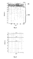
- the general methodology for treating these abnormal combustions is schematized on the figure 1 , with initially a phase of prevention ( PP ) to limit as much as possible the chances of occurrence of the phenomenon, then a phase of detection ( PD ) when the prevention was not enough to avoid the phenomenon, to determine if yes or not it is necessary to intervene in the same cycle where the pre-ignition was detected by means of a corrective phase ( PC ).
- PP phase of prevention
- PD phase of detection
- the detection phase includes a signal acquisition phase and then a signal processing phase to detect the appearance of the high-load pre-ignition, to characterize it and to quantify it.
- the detection thus made does not make it possible to act during the very cycle of the detection. Corrective actions of this type of pre-ignition can therefore be performed only after the occurrence of such a phenomenon, which can seriously affect the integrity of the engine.
- FR 2,897,900 The method described in the patent is also known.
- FR 2,897,900 According to this method, it is possible to act more quickly after the detection of the pre-ignition: one is able to act during the same cycle as the detection cycle of the phenomenon.
- the threshold signal is previously calculated, that is to say before the operation of the engine, and then stored in data tables of the computer, called maps.
- the subject of the invention relates to an alternative method for detecting in real time the occurrence of a high-load pre-ignition phenomenon (of the rumble type), of characterizing it and of quantifying it, with the devices and systems commonly used in engines, so as to take measures to avoid it in the further operation of the engine, during the same cycle as that of detection.
- the method is based on a characterization of values of combustion indicators, CA10 for example, over several cycles, while avoiding cycles for which a pre-ignition occurs.
- the signal may be a continuous measurement of pressure within the cylinder.
- the indicator may be the crankshaft angle where 10% of the energy introduced has been released.
- the parameter characterizing the distribution is determined by means of a robust estimator.
- the quality criterion of the modeling can correspond to a sum of quadratic differences between the experimental distribution a priori and the modeled distribution, or to a sum of absolute differences between the experimental distribution a priori and the distribution modeled.
- the threshold can be determined by defining a tolerance on the parameter characterizing the distribution.
- the threshold may be a sum of the reduced average of N indicator values and k times the standard deviation of said N values, where k is a positive or negative real.
- a supercharged spark ignition internal combustion engine in particular of the gasoline type, comprises at least one cylinder 12 with a combustion chamber 14 inside which combustion of a mixture of supercharged air and fuel.
- the cylinder comprises at least one pressurized fuel supply means 16, for example in the form of a fuel injector 18 controlled by a valve 20, which opens into the combustion chamber, at least one intake means of 22 with a valve 24 associated with an intake manifold 26 terminating in a plenum 26b (not shown in the figure), at least one exhaust gas exhaust means 28 with a valve 30 and an exhaust manifold 32 and at least one ignition means 34, such as a spark plug, which makes it possible to generate one or more sparks making it possible to ignite the fuel mixture present in the combustion chamber.
- a fuel injector 18 controlled by a valve 20
- a valve 24 associated with an intake manifold 26 terminating in a plenum 26b (not shown in the figure)
- at least one exhaust gas exhaust means 28 with a valve 30 and an exhaust manifold 32
- at least one ignition means 34 such as a spark plug
- the pipes 32 of the exhaust means 28 of this engine are connected to an exhaust manifold 36 itself connected to an exhaust line 38.
- a supercharging device 40 for example a turbocharger or a positive displacement compressor, is placed on this exhaust line and comprises a drive stage 42 with a turbine swept by the exhaust gas flowing in the exhaust line and a compression stage 44 which makes it possible to admit an intake air under pressure in the combustion chambers 14 through the intake manifolds 26.
- the engine comprises means 46a for measuring the cylinder pressure, arranged within the cylinder 12 of the engine.
- These measuring means are generally constituted by a pressure sensor which makes it possible to generate a signal representative of the evolution of the pressure in a cylinder.
- the engine may also include means 46b for measuring the intake pressure, arranged in the plenum 26b.
- These measuring means are generally constituted by an absolute pressure sensor, of piezoelectric type, which makes it possible to generate a signal representative of the evolution of the admission pressure in the intake plenum.
- the engine also comprises a calculation and control unit 48, called engine computer, which is connected by conductors (for some bi-directional) to the various organs and sensors of the engine so as to receive the different signals emitted by these sensors, such as the water temperature or the temperature of the oil, to treat them by calculation and then to order the organs of this engine to ensure its proper functioning.
- engine computer a calculation and control unit 48, called engine computer, which is connected by conductors (for some bi-directional) to the various organs and sensors of the engine so as to receive the different signals emitted by these sensors, such as the water temperature or the temperature of the oil, to treat them by calculation and then to order the organs of this engine to ensure its proper functioning.
- the spark plugs 34 are connected by conductors 50 to the engine control unit 48 so as to control the moment of ignition of the fuel mixture
- the cylinder pressure sensor 46a is connected by a line 52 to the same engine computer to send the signals to it.
- Representative of the evolution of the pressure in the cylinder, and the control valves 20 of the injectors 18, are connected by conductors 54 to the computer 48 to control the injection of fuel into the combustion chambers.
- the means 46b are also connected by a line 53 to the motor calculator 48.
- a signal representative of the state of combustion is recorded by means of a sensor placed in the engine.
- the cylinder pressure is chosen.
- the measurement of the cylinder pressure is carried out from the means 46a for measuring the cylinder pressure.
- the instrumentation of the cylinders for a measurement of pressure is more and more common on the vehicles.
- the CA10 is chosen.
- the CA10 corresponds to the crankshaft angle where 10% of the energy introduced has been released or, according to the convention used, 10% of the total energy released.
- a normal combustion that is to say without pre-ignition phenomenon, is characterized by determining one or more characteristic parameters of the distribution of N CA10 values calculated on the N-1 cycles preceding and the cycle in progress, by getting rid of so-called "extreme" values.
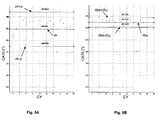
- the figure 5 illustrates the result of the method.
- the Figures 5A and 5B represent a distribution of CA10 values as a function of the cycle.
- the line denoted m indicates the average, and ⁇ indicates the standard deviation.
- the mean and the standard deviation are calculated from classical statistics.
- the mean and the standard deviation are obtained from robust statistics denoted Rm and R ⁇ .
- the cycle-to-cycle dispersion of the combustion is generally represented by a normal law, to which is associated an average, which serves as a reference for characterizing the behavior of the engine, and a standard deviation which is conventionally used to quantify the stability of the quantity observed.
- a normal law to which is associated an average, which serves as a reference for characterizing the behavior of the engine
- a standard deviation which is conventionally used to quantify the stability of the quantity observed.
- the standard standard deviation is not always representative of the stability, and that the modeling of the cyclic dispersion by a normal law is not optimal under certain conditions, as the figure 6 .
- the histogram of values of CA10 the ordinate represents the density D
- Lnorm normal law
- This instability of combustion can be directly felt by the user through for example misfire (problem of driving pleasure but also polluting emissions), and it can also be linked in some extreme cases to abnormal combustion. may cause the destruction of the engine (problem of pre-ignition at high load on spark ignition engines).
- the method of modeling the distribution according to the invention makes it possible to provide more relevant information than a "mean / standard deviation" pair calculated in the normal law sense. This is important for detecting abnormal combustion such as pre-ignition.
- Modeling of normal combustions alone can not be performed from the full sample of N cycles.
- Removing the X cycles for which the CA10 values are the lowest, is to remove the sample values that potentially correspond to pre-ignitions.
- the algorithm eliminates all pre-ignitions and thus leads to a sample consisting only of combustion normally initiated at the candle.
- the detection threshold between the pre-ignitions and the normal combustions is thus fixed automatically by this algorithm when the modeling criterion indicates an optimal modeling.
- one or more characteristic parameters of this distribution are calculated.
- the following parameters can be used: average, median, asymmetry factor, or a flattening factor.
- thresholds are defined. These thresholds make it possible to define whether or not a given value of CA10 belongs to the distribution of the CA10 values of the N preceding cycles, without taking into account combustion with pre-ignition.
- the calculated thresholds are dynamic because they evolve at each cycle.
- the distribution of the CA10 values of the N preceding cycles is characterized, while avoiding the extreme values.
- the parameters used to characterize this distribution then serve to define a threshold.
- the distribution is again characterized and the threshold is modified.
- a threshold is defined from the parameters characterizing a distribution of CA10 values obtained during combustion without pre-ignition, and a tolerance on these parameters: robust average and tolerance related to the standard deviation for example.
- the CA10 is calculated on the current cycle and compared with the defined threshold, so as to detect the start of an abnormal combustion by comparing the combustion indicator (CA10) with the threshold.
- the engine computer can detect the beginning of an abnormal "rumble” or "pre-ignition” type combustion in the combustion chamber.
- this computer In the event of abnormal combustion, this computer then initiates the actions necessary to control this combustion in order to avoid the continuation of such combustion.
- this control of the combustion is achieved by a fuel injection at a crankshaft angle determined by the injectors 18. More specifically, the computer controls the valves 20 so that the cylinder injector concerned allows for introducing into the combustion chamber a quantity of fuel in liquid form.
- the amount of fuel reinjected depends on the constitution of the engine and can range from 10% to 200% of the amount of fuel initially introduced into the combustion chamber.
- the reinjected fuel serves to thwart the flame that begins to unfold during the abnormal combustion. This reinjection allows either to blow this flame, or to stifle this flame by increasing the richness of the fuel mixture.
- the fuel injected in liquid form uses the heat present around this flame to vaporize and the temperature conditions around the flame will drop by retarding the combustion of the fuel mixture and especially its auto-ignition.
- agents to stop the abnormal combustion can be introduced into the combustion chamber.
- these agents may be water in vapor or liquid form, or carbon dioxide.
- the engine comprises additional specific injectors for the introduction of these agents in association with a dedicated circuit (pump, tank, ).
- This relief valve may be either an additional valve or the inlet valve 24 and / or the exhaust valve 30.
- the present invention may also relate to a spark ignition engine and indirect injection.
- the control of the unfolding of the abnormal combustion will be done by the use of a specific injector (fuel, water, CO2), as mentioned above, or by valve opening.
- Indicators derived from cylinder pressure or an ionization signal are preferred. Indeed, a good characterization of the pre-ignition requires above all to define indicators that are as representative as possible of the state of progress of the combustion in the room.
- An indicator such as the CA10 is for example more robust than a derived indicator, an instantaneous torque measurement due to the "distance" of this measurement (the torque recovered on the crankshaft is an image of the recovered energy after combustion, and not directly an image of the course of combustion). Engine monitoring can, however, be considered from these torque and speed measurements.
- the invention is not limited to the use of a single indicator. Indeed, it may be advantageous to combine several quantities at a time by using a multi-criterion threshold, or a threshold for each indicator.
Landscapes
- Engineering & Computer Science (AREA)
- Chemical & Material Sciences (AREA)
- Combustion & Propulsion (AREA)
- Mechanical Engineering (AREA)
- General Engineering & Computer Science (AREA)
- Physics & Mathematics (AREA)
- General Physics & Mathematics (AREA)
- Combined Controls Of Internal Combustion Engines (AREA)
Applications Claiming Priority (1)
| Application Number | Priority Date | Filing Date | Title |
|---|---|---|---|
| FR0805580A FR2937086B1 (fr) | 2008-10-09 | 2008-10-09 | Procede de detection de combustion anormale pour moteurs a combustion interne |
Publications (1)
| Publication Number | Publication Date |
|---|---|
| EP2175121A1 true EP2175121A1 (de) | 2010-04-14 |
Family
ID=40748682
Family Applications (1)
| Application Number | Title | Priority Date | Filing Date |
|---|---|---|---|
| EP09290720A Withdrawn EP2175121A1 (de) | 2008-10-09 | 2009-09-18 | Verfahren zur Erkennung einer anormalen Verbrennung für Verbrennungsmotoren |
Country Status (4)
| Country | Link |
|---|---|
| US (1) | US8068972B2 (de) |
| EP (1) | EP2175121A1 (de) |
| JP (1) | JP5619404B2 (de) |
| FR (1) | FR2937086B1 (de) |
Cited By (1)
| Publication number | Priority date | Publication date | Assignee | Title |
|---|---|---|---|---|
| EP2672095A1 (de) * | 2011-02-02 | 2013-12-11 | Toyota Jidosha Kabushiki Kaisha | Steuerungsvorrichtung für einen verbrennungsmotor |
Families Citing this family (36)
| Publication number | Priority date | Publication date | Assignee | Title |
|---|---|---|---|---|
| FR2952678B1 (fr) * | 2009-11-13 | 2012-07-13 | Inst Francais Du Petrole | Procede de detection de combustion anormale pour moteurs a combustion interne a partir de plusieurs indicateurs de la combustion |
| FR2952679B1 (fr) * | 2009-11-13 | 2012-02-24 | Inst Francais Du Petrole | Procede de detection de combustion anormale pour moteurs a combustion interne a partir de modelisations de distributions d'indicateurs de combustion |
| FR2962767B1 (fr) * | 2010-07-13 | 2012-07-13 | Inst Francais Du Petrole | Procede de controle de la phase de combustion d'un melange carbure d'un moteur a combustion interne suralimente a allumage commande, notamment de type essence. |
| US9845752B2 (en) | 2010-09-29 | 2017-12-19 | GM Global Technology Operations LLC | Systems and methods for determining crankshaft position based indicated mean effective pressure (IMEP) |
| US8838365B2 (en) | 2011-03-24 | 2014-09-16 | Ford Global Technologies, Llc | Method and system for pre-ignition control |
| US8095297B2 (en) * | 2011-03-24 | 2012-01-10 | Ford Global Technologies, Llc | Method and system for pre-ignition control |
| US8171912B2 (en) | 2011-04-20 | 2012-05-08 | Ford Global Technologies, Llc | Method and system for pre-ignition control |
| FR2978209B1 (fr) * | 2011-07-21 | 2013-07-12 | IFP Energies Nouvelles | Procede de detection et de caracterisation de combustion anormale pour moteurs a combustion interne |
| US9127604B2 (en) | 2011-08-23 | 2015-09-08 | Richard Stephen Davis | Control system and method for preventing stochastic pre-ignition in an engine |
| US9097196B2 (en) * | 2011-08-31 | 2015-08-04 | GM Global Technology Operations LLC | Stochastic pre-ignition detection systems and methods |
| US9038596B2 (en) | 2011-12-02 | 2015-05-26 | Ford Global Technologies, Llc | Method and system for pre-ignition control |
| US9551288B2 (en) | 2012-06-29 | 2017-01-24 | Ford Global Technologies, Llc | Method and system for pre-ignition control |
| US8997723B2 (en) | 2012-06-29 | 2015-04-07 | Ford Global Technologies, Llc | Method and system for pre-ignition control |
| US9043122B2 (en) | 2012-06-29 | 2015-05-26 | Ford Global Technologies, Llc | Method and system for pre-ignition control |
| US9121362B2 (en) | 2012-08-21 | 2015-09-01 | Brian E. Betz | Valvetrain fault indication systems and methods using knock sensing |
| US9133775B2 (en) | 2012-08-21 | 2015-09-15 | Brian E. Betz | Valvetrain fault indication systems and methods using engine misfire |
| DE102012018405A1 (de) | 2012-09-17 | 2014-05-15 | Mtu Friedrichshafen Gmbh | Verfahren zum Betreiben eines Verbrennungsmotors |
| US8973429B2 (en) | 2013-02-25 | 2015-03-10 | GM Global Technology Operations LLC | System and method for detecting stochastic pre-ignition |
| US9556810B2 (en) | 2014-12-31 | 2017-01-31 | General Electric Company | System and method for regulating exhaust gas recirculation in an engine |
| US9752949B2 (en) | 2014-12-31 | 2017-09-05 | General Electric Company | System and method for locating engine noise |
| US9803567B2 (en) | 2015-01-07 | 2017-10-31 | General Electric Company | System and method for detecting reciprocating device abnormalities utilizing standard quality control techniques |
| US9528445B2 (en) | 2015-02-04 | 2016-12-27 | General Electric Company | System and method for model based and map based throttle position derivation and monitoring |
| US9791343B2 (en) | 2015-02-12 | 2017-10-17 | General Electric Company | Methods and systems to derive engine component health using total harmonic distortion in a knock sensor signal |
| US9695761B2 (en) | 2015-03-11 | 2017-07-04 | General Electric Company | Systems and methods to distinguish engine knock from piston slap |
| US9435244B1 (en) | 2015-04-14 | 2016-09-06 | General Electric Company | System and method for injection control of urea in selective catalyst reduction |
| US10012155B2 (en) | 2015-04-14 | 2018-07-03 | Woodward, Inc. | Combustion pressure feedback based engine control with variable resolution sampling windows |
| US9784231B2 (en) | 2015-05-06 | 2017-10-10 | General Electric Company | System and method for determining knock margin for multi-cylinder engines |
| US9784635B2 (en) | 2015-06-29 | 2017-10-10 | General Electric Company | Systems and methods for detection of engine component conditions via external sensors |
| CN107742028B (zh) * | 2017-10-17 | 2020-09-22 | 长江大学 | 一种五缸往复泵曲轴上曲柄初相角优化布置方法 |
| WO2019123129A1 (en) * | 2017-12-18 | 2019-06-27 | King Abdullah University Of Science And Technology | Controlling heat release within an engine cylinder |
| JP6848889B2 (ja) * | 2018-01-22 | 2021-03-24 | マツダ株式会社 | エンジン |
| JP2019210834A (ja) * | 2018-06-01 | 2019-12-12 | トヨタ自動車株式会社 | 内燃機関の制御装置 |
| JP2019210831A (ja) * | 2018-06-01 | 2019-12-12 | トヨタ自動車株式会社 | 内燃機関の制御装置 |
| US10934965B2 (en) | 2019-04-05 | 2021-03-02 | Woodward, Inc. | Auto-ignition control in a combustion engine |
| CN113267291B (zh) * | 2021-05-28 | 2022-08-26 | 清华大学 | 燃烧振荡现象的预警监测方法及装置 |
| CN115341994B (zh) * | 2022-08-15 | 2023-02-24 | 武汉优泰电子技术有限公司 | 一种往复式发动机燃烧状态评价方法、装置及计算机设备 |
Citations (5)
| Publication number | Priority date | Publication date | Assignee | Title |
|---|---|---|---|---|
| DE102004033072A1 (de) * | 2004-01-07 | 2005-07-28 | Robert Bosch Gmbh | Verfahren und Vorrichtung zur Steuerung einer Brennkraftmaschine |
| WO2007001064A1 (en) * | 2005-06-28 | 2007-01-04 | Toyota Jidosha Kabushiki Kaisha | Knocking state determination device |
| US20070016387A1 (en) * | 2005-07-15 | 2007-01-18 | Denso Corporation | Knock determining apparatus |
| FR2897900A1 (fr) | 2006-02-28 | 2007-08-31 | Inst Francais Du Petrole | Procede de controle de la phase de combustion d'un moteur a combustion interne, notamment moteur suralimente a injection directe de type essence |
| EP1828737A1 (de) | 2004-12-17 | 2007-09-05 | Institut Français du Pétrole | Verfahren zur detektion von abnormaler verbrennung für verbrennungsmotor |
Family Cites Families (3)
| Publication number | Priority date | Publication date | Assignee | Title |
|---|---|---|---|---|
| JPH09273436A (ja) * | 1995-11-10 | 1997-10-21 | Yamaha Motor Co Ltd | エンジンの制御方法 |
| JP3959784B2 (ja) * | 1997-05-28 | 2007-08-15 | 日産自動車株式会社 | 直噴式火花点火エンジンの燃焼安定化装置 |
| JP3931765B2 (ja) * | 2002-08-28 | 2007-06-20 | トヨタ自動車株式会社 | エンジンの制御装置及び方法、ハイブリッド型の動力出力装置並びにハイブリッド車両 |
-
2008
- 2008-10-09 FR FR0805580A patent/FR2937086B1/fr not_active Expired - Fee Related
-
2009
- 2009-09-18 EP EP09290720A patent/EP2175121A1/de not_active Withdrawn
- 2009-09-28 US US12/567,934 patent/US8068972B2/en not_active Expired - Fee Related
- 2009-10-09 JP JP2009235056A patent/JP5619404B2/ja not_active Expired - Fee Related
Patent Citations (5)
| Publication number | Priority date | Publication date | Assignee | Title |
|---|---|---|---|---|
| DE102004033072A1 (de) * | 2004-01-07 | 2005-07-28 | Robert Bosch Gmbh | Verfahren und Vorrichtung zur Steuerung einer Brennkraftmaschine |
| EP1828737A1 (de) | 2004-12-17 | 2007-09-05 | Institut Français du Pétrole | Verfahren zur detektion von abnormaler verbrennung für verbrennungsmotor |
| WO2007001064A1 (en) * | 2005-06-28 | 2007-01-04 | Toyota Jidosha Kabushiki Kaisha | Knocking state determination device |
| US20070016387A1 (en) * | 2005-07-15 | 2007-01-18 | Denso Corporation | Knock determining apparatus |
| FR2897900A1 (fr) | 2006-02-28 | 2007-08-31 | Inst Francais Du Petrole | Procede de controle de la phase de combustion d'un moteur a combustion interne, notamment moteur suralimente a injection directe de type essence |
Non-Patent Citations (1)
| Title |
|---|
| G., SAPORTA: "Probabilité analyse des données et statistique", 1990, pages: 311 - 313 |
Cited By (2)
| Publication number | Priority date | Publication date | Assignee | Title |
|---|---|---|---|---|
| EP2672095A1 (de) * | 2011-02-02 | 2013-12-11 | Toyota Jidosha Kabushiki Kaisha | Steuerungsvorrichtung für einen verbrennungsmotor |
| EP2672095A4 (de) * | 2011-02-02 | 2014-11-05 | Toyota Motor Co Ltd | Steuerungsvorrichtung für einen verbrennungsmotor |
Also Published As
| Publication number | Publication date |
|---|---|
| US8068972B2 (en) | 2011-11-29 |
| JP2010106828A (ja) | 2010-05-13 |
| FR2937086A1 (fr) | 2010-04-16 |
| FR2937086B1 (fr) | 2013-05-24 |
| US20100094528A1 (en) | 2010-04-15 |
| JP5619404B2 (ja) | 2014-11-05 |
Similar Documents
| Publication | Publication Date | Title |
|---|---|---|
| EP2175121A1 (de) | Verfahren zur Erkennung einer anormalen Verbrennung für Verbrennungsmotoren | |
| EP2166214B1 (de) | Verfahren zur Erkennung einer anormalen Verbrennung für Verbrennungsmotoren | |
| EP2325461A1 (de) | Verfahren zur Erfassung fehlerhafter Verbrennungen bei einem Verbrennungsmotor basierend auf modellierten Verteilungen von Verbrennungsindikatoren | |
| FR2952678A1 (fr) | Procede de detection de combustion anormale pour moteurs a combustion interne a partir de plusieurs indicateurs de la combustion | |
| EP1828737B1 (de) | Verfahren zur detektion von abnormaler verbrennung für verbrennungsmotor | |
| EP1826379A1 (de) | Verfahren zur Regelung der Brennphase einer Brennkraftmaschine, insbesondere einer aufgeladenen, direkteinspritzenden Benzin-Brennkraftmaschine | |
| FR2919671A1 (fr) | Procede de diagnostic d'un moteur a combustion interne par analyse des gaz d'echappement et dispositif de mise en oeuvre. | |
| EP2549087B1 (de) | Verfahren zur Erkennung und Charakterisierung einer anormalen Verbrennung für Verbrennungsmotoren | |
| EP3626954B1 (de) | Verfahren zur bestimmung einer klopfanzeige durch bestimmung des gesamtdrucks im zylinder | |
| EP2166216A1 (de) | Verfahren zur Steuerung der Verbrennung eines Gemisches für eine fremdgezündete Brennkraftmaschine | |
| EP2184597A1 (de) | Verfahren zur Verbrennungskontrolle eines Motors, der im Schichtmodus funktioniert | |
| FR2923294A1 (fr) | Procede de detection de combustion anormale | |
| FR2904044A1 (fr) | Procede de commande d'un moteur comprenant une etape amelioree de detection du debut d'une combustion. | |
| WO2017144789A1 (fr) | Procede de controle de combustion d'un moteur thermique par un procede de baisse de charge immediate | |
| EP1923558A1 (de) | Steuersystem und -verfahren eines Verbrennungsmotors | |
| FR3118101A1 (fr) | Procédé de détermination d’un indicateur de cliquetis de la combustion par détermination d’extrema locaux de la pression | |
| FR3028565A1 (fr) | Procede de diagnostic de l'encrassement d'un filtre a air equipant un moteur a combustion interne suralimente | |
| FR3118102A1 (fr) | Procédé de détermination d’un indicateur de cliquetis de la combustion à partir de mesures d'accélération | |
| FR3072727A1 (fr) | Procede de diagnostic d’un endommagement d’un moteur par des pre-allumages | |
| WO2007074271A1 (fr) | Procede de commande d'un moteur permettant une amelioration d'un diagnostic de combustion du moteur | |
| WO2017144790A1 (fr) | Procédé de gestion préventive de combustions anormales dans un moteur thermique | |
| FR3048266A1 (fr) | Procede de limitation de charge d'un moteur thermique sur avance a l'allumage degradee | |
| WO2017088967A1 (fr) | Procédé de commande pour le démarrage d'un moteur à combustion comportant une phase de thermie et une phase de génération de couple |
Legal Events
| Date | Code | Title | Description |
|---|---|---|---|
| PUAI | Public reference made under article 153(3) epc to a published international application that has entered the european phase |
Free format text: ORIGINAL CODE: 0009012 |
|
| AK | Designated contracting states |
Kind code of ref document: A1 Designated state(s): AT BE BG CH CY CZ DE DK EE ES FI FR GB GR HR HU IE IS IT LI LT LU LV MC MK MT NL NO PL PT RO SE SI SK SM TR |
|
| AX | Request for extension of the european patent |
Extension state: AL BA RS |
|
| RAP1 | Party data changed (applicant data changed or rights of an application transferred) |
Owner name: IFP ENERGIES NOUVELLES |
|
| 17P | Request for examination filed |
Effective date: 20101014 |
|
| 17Q | First examination report despatched |
Effective date: 20101108 |
|
| RAP1 | Party data changed (applicant data changed or rights of an application transferred) |
Owner name: IFP ENERGIES NOUVELLES |
|
| STAA | Information on the status of an ep patent application or granted ep patent |
Free format text: STATUS: THE APPLICATION IS DEEMED TO BE WITHDRAWN |
|
| 18D | Application deemed to be withdrawn |
Effective date: 20190719 |