EP2184597A1 - Verfahren zur Verbrennungskontrolle eines Motors, der im Schichtmodus funktioniert - Google Patents
Verfahren zur Verbrennungskontrolle eines Motors, der im Schichtmodus funktioniert Download PDFInfo
- Publication number
- EP2184597A1 EP2184597A1 EP09290728A EP09290728A EP2184597A1 EP 2184597 A1 EP2184597 A1 EP 2184597A1 EP 09290728 A EP09290728 A EP 09290728A EP 09290728 A EP09290728 A EP 09290728A EP 2184597 A1 EP2184597 A1 EP 2184597A1
- Authority
- EP
- European Patent Office
- Prior art keywords
- combustion
- distribution
- values
- indicator
- threshold
- Prior art date
- Legal status (The legal status is an assumption and is not a legal conclusion. Google has not performed a legal analysis and makes no representation as to the accuracy of the status listed.)
- Withdrawn
Links
Images


Classifications
-
- F—MECHANICAL ENGINEERING; LIGHTING; HEATING; WEAPONS; BLASTING
- F02—COMBUSTION ENGINES; HOT-GAS OR COMBUSTION-PRODUCT ENGINE PLANTS
- F02D—CONTROLLING COMBUSTION ENGINES
- F02D41/00—Electrical control of supply of combustible mixture or its constituents
- F02D41/02—Circuit arrangements for generating control signals
- F02D41/14—Introducing closed-loop corrections
- F02D41/1497—With detection of the mechanical response of the engine
- F02D41/1498—With detection of the mechanical response of the engine measuring engine roughness
-
- F—MECHANICAL ENGINEERING; LIGHTING; HEATING; WEAPONS; BLASTING
- F02—COMBUSTION ENGINES; HOT-GAS OR COMBUSTION-PRODUCT ENGINE PLANTS
- F02D—CONTROLLING COMBUSTION ENGINES
- F02D35/00—Controlling engines, dependent on conditions exterior or interior to engines, not otherwise provided for
- F02D35/02—Controlling engines, dependent on conditions exterior or interior to engines, not otherwise provided for on interior conditions
- F02D35/023—Controlling engines, dependent on conditions exterior or interior to engines, not otherwise provided for on interior conditions by determining the cylinder pressure
-
- F—MECHANICAL ENGINEERING; LIGHTING; HEATING; WEAPONS; BLASTING
- F02—COMBUSTION ENGINES; HOT-GAS OR COMBUSTION-PRODUCT ENGINE PLANTS
- F02D—CONTROLLING COMBUSTION ENGINES
- F02D41/00—Electrical control of supply of combustible mixture or its constituents
- F02D41/30—Controlling fuel injection
- F02D41/3011—Controlling fuel injection according to or using specific or several modes of combustion
- F02D41/3017—Controlling fuel injection according to or using specific or several modes of combustion characterised by the mode(s) being used
- F02D41/3023—Controlling fuel injection according to or using specific or several modes of combustion characterised by the mode(s) being used a mode being the stratified charge spark-ignited mode
-
- G—PHYSICS
- G01—MEASURING; TESTING
- G01M—TESTING STATIC OR DYNAMIC BALANCE OF MACHINES OR STRUCTURES; TESTING OF STRUCTURES OR APPARATUS, NOT OTHERWISE PROVIDED FOR
- G01M15/00—Testing of engines
- G01M15/04—Testing internal-combustion engines
- G01M15/11—Testing internal-combustion engines by detecting misfire
-
- F—MECHANICAL ENGINEERING; LIGHTING; HEATING; WEAPONS; BLASTING
- F02—COMBUSTION ENGINES; HOT-GAS OR COMBUSTION-PRODUCT ENGINE PLANTS
- F02D—CONTROLLING COMBUSTION ENGINES
- F02D41/00—Electrical control of supply of combustible mixture or its constituents
- F02D41/02—Circuit arrangements for generating control signals
- F02D41/14—Introducing closed-loop corrections
- F02D41/1401—Introducing closed-loop corrections characterised by the control or regulation method
- F02D2041/1433—Introducing closed-loop corrections characterised by the control or regulation method using a model or simulation of the system
-
- F—MECHANICAL ENGINEERING; LIGHTING; HEATING; WEAPONS; BLASTING
- F02—COMBUSTION ENGINES; HOT-GAS OR COMBUSTION-PRODUCT ENGINE PLANTS
- F02D—CONTROLLING COMBUSTION ENGINES
- F02D2200/00—Input parameters for engine control
- F02D2200/02—Input parameters for engine control the parameters being related to the engine
- F02D2200/10—Parameters related to the engine output, e.g. engine torque or engine speed
- F02D2200/1015—Engines misfires
-
- F—MECHANICAL ENGINEERING; LIGHTING; HEATING; WEAPONS; BLASTING
- F02—COMBUSTION ENGINES; HOT-GAS OR COMBUSTION-PRODUCT ENGINE PLANTS
- F02D—CONTROLLING COMBUSTION ENGINES
- F02D35/00—Controlling engines, dependent on conditions exterior or interior to engines, not otherwise provided for
- F02D35/02—Controlling engines, dependent on conditions exterior or interior to engines, not otherwise provided for on interior conditions
- F02D35/028—Controlling engines, dependent on conditions exterior or interior to engines, not otherwise provided for on interior conditions by determining the combustion timing or phasing
Definitions
- the present invention relates to the field of controlling the combustion of an internal combustion engine. It relates more particularly to such a method applied to a spark ignition engine operating in stratified mode.
- Another mode of operation aims to improve the efficiency of the spark ignition engine when operating under low load. It consists in admitting a generally poor mixture in the combustion chamber, that is to say a mixture with an excess of air. This dilution of the fuel mixture is effected by fully opening the throttle valve and regulating the engine torque (i.e. the load) by playing only on the amount of fuel injected. Operating with a throttle open at most allows to eliminate, or at least greatly reduce losses by pumping the engine (as a reminder, these losses reflect the need to bring work to the engine to drain the combustion chamber after combustion by pushing the flue gases but also to admit fresh gases during admission).
- this lean mixture does not have to be homogenous because a homogeneous lean mixture would quickly reach the flammability limits of the fuel. It would be impossible to light the mixture with a candle. It is why, we intentionally seek to locate the fuel around the spark plug to thereby create a mixing pocket with a richness conducive to ignition, while at the scale of the chamber, the mixture remains overall very poor. It is this stratification of wealth that makes it possible to operate with untouchable low wealth with a homogeneous mixture (up to 0.2 of wealth).
- the main problem associated with this mode of combustion concerns the treatment of exhaust gases.
- the fact of not operating at richness 1 unbalances the polluting emissions and complicates the post-treatment system, in particular with regard to the emissions of particularly high nitrogen oxides in lean mixture.
- the formation of NOx depends in fact on the first order of the maximum temperature reached during the combustion and the richness (the higher the temperature and the poor, and the more NOx emissions may be important).
- the object of the invention relates to an alternative method for controlling the combustion in spark ignition engines operating in stratified mode.
- the method is based on a characterization of values of indicators of stability of the combustion, the PMI for example, while avoiding the cycles for which an instability occurs.
- the signal used may be a continuous measurement of pressure within the cylinder, and the indicator may be selected from the following indicators: the indicated average pressure, the angle CA10 (the crankshaft angle for which ten percent of the fuel is consumed during combustion), the maximum cylinder pressure, the torque and the instantaneous regimes, and the release of energy.
- the indicator may be selected from the following indicators: the indicated average pressure, the angle CA10 (the crankshaft angle for which ten percent of the fuel is consumed during combustion), the maximum cylinder pressure, the torque and the instantaneous regimes, and the release of energy.
- the parameter characterizing the distribution is determined by means of a robust estimator.
- the quality criterion of the modeling can correspond to a sum of quadratic differences between the experimental distribution a priori and the modeled distribution, or to a sum of absolute differences between the experimental distribution a priori and the distribution modeled.
- the threshold can be determined by defining a tolerance on the parameter characterizing the distribution. This threshold can thus correspond to a sum of the reduced average of N indicator values and k times the standard deviation of said N values, where k is a positive or negative real.
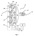
- a spark ignition internal combustion engine 10 in particular of gasoline type, comprises at least one cylinder 12 with a combustion chamber 14 inside which combustion of a mixture of air and fuel occurs.
- the cylinder comprises at least one pressurized fuel supply means 16, for example in the form of a fuel injector 18 controlled by a valve 20, which opens into the combustion chamber, at least one intake means of 22 with a valve 24 associated with an intake manifold 26 terminating in a plenum 26b (not shown in FIG. figure 1 ), at least one exhaust gas exhaust means 28 with a valve 30 and an exhaust pipe 32 and at least one ignition means 34, such as a spark plug, which makes it possible to generate one or more sparks for igniting the fuel mixture present in the combustion chamber.
- This engine has the particularity of being able to operate in "laminate” mode.
- This stratification of the mixture of air and fuel can be classically obtained by three main methods.
- the first is to position the fuel supply means (the injector 18) near the ignition means 34 so that the flammable fuel mixture arrives naturally around the ignition means 34 at the time of ignition.
- This first solution is generally described as "spray guided”.
- the second solution consists in maintaining the stratification of the mixture by virtue of the movements of air created in the combustion chamber 14 by the air entering through the intake manifolds 26. This internal aerodynamics is then also used to guide the fuel up to ignition means 34.
- This second solution is generally described as "air guided”.
- the third method is to use the walls of the combustion chamber 14 and the piston to guide the fuel to the ignition means 34. This third solution is generally referred to as "wall guided”.
- the pipes 32 of the exhaust means 28 of this engine are connected to an exhaust manifold 36 itself connected to an exhaust line 38.
- This type of “laminated” operation can be implemented both on the so-called “atmospheric” engines and on supercharged engines. That's why, as part of this example of the figure 1 , a supercharging device 40, for example a turbocharger, is placed on this exhaust line and comprises a drive stage 42 with an exhaust gas-swept turbine circulating in the exhaust line and a compression stage 44 which allows to admit an air of admission under pressure into the combustion chambers 14 via the intake manifolds 26.
- a supercharging device 40 for example a turbocharger
- the engine comprises means 46a for measuring the cylinder pressure, arranged within the cylinder 12 of the engine.
- These measuring means are generally constituted by a pressure sensor which makes it possible to generate a signal representative of the evolution of the pressure in a cylinder.
- the engine may also include means 46b for measuring the intake pressure, disposed in the plenum 26b.
- These measuring means are generally constituted by an absolute pressure sensor, of piezoelectric type, which makes it possible to generate a signal representative of the evolution of the admission pressure in the intake plenum.
- the engine also comprises a calculation and control unit 48, called engine computer, which is connected by conductors (for some bi-directional) to the various organs and sensors of the engine so as to receive the different signals emitted by these sensors, such as the water temperature or the temperature of the oil, to treat them by calculation and then to order the organs of this engine to ensure its proper functioning.
- engine computer a calculation and control unit 48, called engine computer, which is connected by conductors (for some bi-directional) to the various organs and sensors of the engine so as to receive the different signals emitted by these sensors, such as the water temperature or the temperature of the oil, to treat them by calculation and then to order the organs of this engine to ensure its proper functioning.
- the spark plugs 34 are connected by conductors 50 to the engine control unit 48 so as to control the moment of ignition of the fuel mixture
- the cylinder pressure sensor 46a is connected by a line 52 to the same engine computer to send the signals to it.
- Representative of the evolution of the pressure in the cylinder, and the control valves 20 of the injectors 18, are connected by conductors 54 to the computer 48 to control the injection of fuel into the combustion chambers.
- the means 46b are also connected by a line 53 to the motor calculator 48.
- this risk of combustion instability is controlled by defining injection and ignition settings, which make it possible to achieve stable combustion under reference operating conditions. Mapped corrections are then made based, for example, on the thermal state of the engine.
- the invention relates to a method for controlling the combustion loop by integrating a detection phase of the lack of stability of combustion in stratified mode, a treatment phase, and a corrective action phase.
- a signal representative of the state of combustion is recorded by means of a sensor placed in the engine.
- the pressure is selected cylinder.
- the measurement of the cylinder pressure is carried out from the means 46a for measuring the cylinder pressure.
- the instrumentation of the cylinders for a measurement of pressure is more and more common on the vehicles. However, one can dispense with a cylinder pressure measurement. It is indeed possible to use independently (or by coupling) more conventional sensors for measuring an instantaneous speed, an instantaneous torque, a vibration level (accelerometer sensor) or an ionization current (by a probe of ionization or a simple candle).
- an indicator of the stability of the combustion is calculated from this signal.
- These may be, for example, the following indicators: PMI, CA10, energy release.
- the PMI is chosen.
- the IMP corresponds to the average pressure indicated. It is also possible to detect a lack of stability by coupling several pieces of information, such as a measurement of pressure in the combustion chamber, an instantaneous speed measurement, an instantaneous torque measurement, a signal derived from an accelerometric sensor, an ionization signal. , ...
- the characterization of a stable combustion that is to say a complete combustion (not degraded) and without misfire, is carried out on line from N values of PMI calculated on the N-1 cycles previous and the cycle in progress.
- the figure 3 illustrates the result of the method, from the data of the figure 2 .
- these parameters are determined by modeling the distribution of the N values of PMI by an iterative process.
- the cycle-to-cycle dispersion of the combustion is generally represented by a normal law, to which is associated an average, which serves as a reference for characterizing the behavior of the engine, and a standard deviation which is conventionally used to quantify the stability of the quantity observed.
- a normal law to which is associated an average, which serves as a reference for characterizing the behavior of the engine
- a standard deviation which is conventionally used to quantify the stability of the quantity observed.
- the standard standard deviation is not always representative of the stability, and that the modeling of the cyclic dispersion by a normal law is not optimal under certain conditions. This instability of combustion can be directly felt by the user through for example misfire (problem of driving pleasure but also polluting emissions).
- the method of modeling the distribution according to the invention makes it possible to provide more relevant information than a "mean / standard deviation" pair calculated in the normal law sense. This is important for detecting unstable combustion.
- the Figures 4A to 4C represent the evolution of the distribution (density D ) experiment over 1000 cycles of the PMI values obtained on the same operating point at 2000 rpm, but with different EGR levels: 10% ( Figure 4A ), 20% ( Figure 4B ) and 30% ( figure 4C ).
- EGR results in a destabilization of combustion (degraded combustions and misfire), visible on stretching of the distribution tail oriented towards low values of PMI.
- a threshold of PMI that is to say a value of PMI limit, below which it is considered that the combustion is unstable, we can determine the amount (or frequency) of cycle for which the combustion is unstable .
- the Figure 4A illustrates that no cycle has a PMI below this threshold, so there is no need to act for a rate of EGR of 10%.
- the Figure 4B illustrates that 2% of the cycles have a PMI lower than this threshold, it may be necessary to act for a rate of EGR of 20%.
- figure 4C illustrates that 6% of cycles have a PMI below this threshold, it is certainly necessary to act for a rate of EGR of 30%.
- Stable combustions alone can not be modeled from the full sample of N cycles.
- Removing the X cycles for which the PMI values are low amounts to removing from the sample values that potentially correspond to unstable combustions.
- the algorithm makes it possible to eliminate all the unstable combustions and thus to arrive at a sample composed only of stable combustions.
- the detection threshold between the stable and unstable combustions is thus fixed automatically by this algorithm when the modeling criterion indicates an optimal modeling.
- one or more characteristic parameters of this distribution are calculated.
- thresholds are defined. These thresholds make it possible to define whether or not a given PMI value belongs to the distribution of the PMI values of the N preceding cycles, without taking into account the unstable combustions.
- the calculated thresholds are dynamic because they evolve at each cycle. Indeed, for each cycle, the distribution of the PMI values of the N preceding cycles is characterized, while avoiding the extreme values. The parameters used to characterize this distribution then serve to define a threshold. In the next cycle, the distribution is again characterized and the threshold is modified.
- the PMI is calculated on the current cycle and is compared with the defined threshold, so as to detect unstable combustion by comparing the stability indicator (PMI) with the threshold.
- the comparison of the stability indicator calculated with the current cycle with the threshold thus makes it possible to detect an unstable combustion (incomplete combustion or misfire).
- the criticality of the instabilities For example, if the frequency of the instabilities is greater than 5%, then it is considered that the combustion is too unstable and that it is necessary to initiate an action Corrective. We can also consider more restrictive criteria at 3 or 2% as the load decreases.
- the engine computer can therefore determine whether the stability of the combustion needs to be improved. Thus, a corrective action is triggered by the engine ECU if the amplitude and / or the frequency of the stability indicator used comes out of the acceptable dispersion.
- This corrective action can be done in several ways depending on the point of operation of the engine and the actuators available. Several actions can be considered simultaneously, for example on the rate of EGR, the injection strategy (injection pressure, number of injections, phasing injections, amount injected on each injection, ...), the strategy of ignition (AVA, charging time, spark train, %), the pressure and temperature conditions at the intake and the exhaust, or at the positions of the VVTs on admission and the exhaust to play on the IGR rate.
- the engine also includes a throttle valve which controls the flow of fresh air entering the engine.
- a throttle valve which controls the flow of fresh air entering the engine.
- the throttling of the intake results in a depression in the plenum and in the ducts.
- the adjustment of this valve makes it possible to adapt the intake pressure to the operating conditions.
- the control of the supercharging member may also make it possible to adapt the intake pressure to the operating conditions.
- the engine also comprises one or more devices for adjusting the distribution (variable lifts and / or variable wedges) so as to be able to change the distribution diagram according to the operating conditions.
- These devices make it possible in particular to change the rate of burnt gases recirculated internally to the engine (IGR - Internal Gas Recirculation) and thus act on the combustion stability.
- the engine also includes one or more external exhaust gas recirculation (EGR) devices.
- EGR exhaust gas recirculation
- the exhaust gases can be taken before or after the aftertreatment systems, and before or after any booster systems. These devices are also used to change the rate of burned gases readmitted into the engine and thus act on the combustion stability.
- the method for detecting unstable combustions in the context of a spark ignition engine operating in stratified mode, can also be used as follows:
- the stability indicators are used to characterize certain critical operating points of the engine, from the development stage on the engine test bench. We obtain a more or less regular mapping of the area. This mapping makes it possible to inform the engine calculator on a mean value of the stability indicator ( ⁇ ) and on an acceptable variation ( ⁇ ) of this magnitude around the average. This variation can be composed of two values, differentiating a positive variation from a negative variation.
- This process can also be auto-adaptive and update acceptable values of average and dispersion throughout the life of the vehicle (this allows for example to detect possible problems of fouling EGR valves, candles or even injectors).
- the process has been illustrated using the PMI as a stability indicator. But other indicators such as CA10, maximum cylinder pressure, torque and instantaneous speeds or energy release can be used.
- the invention is not limited to the use of a single stability indicator. Indeed, it may be advantageous to combine several indicators at a time, using a multi-criteria threshold, or a threshold for each indicator.
Applications Claiming Priority (1)
| Application Number | Priority Date | Filing Date | Title |
|---|---|---|---|
| FR0806206A FR2938017B1 (fr) | 2008-11-06 | 2008-11-06 | Procede de controle de la combustion d'un moteur fonctionnant en mode stratifie |
Publications (1)
| Publication Number | Publication Date |
|---|---|
| EP2184597A1 true EP2184597A1 (de) | 2010-05-12 |
Family
ID=40756350
Family Applications (1)
| Application Number | Title | Priority Date | Filing Date |
|---|---|---|---|
| EP09290728A Withdrawn EP2184597A1 (de) | 2008-11-06 | 2009-09-25 | Verfahren zur Verbrennungskontrolle eines Motors, der im Schichtmodus funktioniert |
Country Status (2)
| Country | Link |
|---|---|
| EP (1) | EP2184597A1 (de) |
| FR (1) | FR2938017B1 (de) |
Cited By (2)
| Publication number | Priority date | Publication date | Assignee | Title |
|---|---|---|---|---|
| WO2022038129A1 (de) * | 2020-08-20 | 2022-02-24 | Rolls-Royce Solutions GmbH | Verfahren zum betreiben einer brennkraftmaschine, steuergerät für eine brennkraftmaschine, und brennkraftmaschine |
| CN117740384A (zh) * | 2024-02-07 | 2024-03-22 | 中国航发四川燃气涡轮研究院 | 一种燃烧性能敏感性评估方法及装置 |
Citations (8)
| Publication number | Priority date | Publication date | Assignee | Title |
|---|---|---|---|---|
| US5278760A (en) * | 1990-04-20 | 1994-01-11 | Hitachi America, Ltd. | Method and system for detecting the misfire of an internal combustion engine utilizing engine torque nonuniformity |
| DE19827105A1 (de) * | 1998-06-18 | 1999-12-23 | Bosch Gmbh Robert | Verfahren zum Betreiben einer Brennkraftmaschine insbesondere eines Kraftfahrzeugs |
| US6292738B1 (en) * | 2000-01-19 | 2001-09-18 | Ford Global Tech., Inc. | Method for adaptive detection of engine misfire |
| FR2851612A1 (fr) * | 2003-02-20 | 2004-08-27 | Siemens Vdo Automotive | Procede de detection de rates de combustion d'un moteur a combustion interne par filtrage des variations de l'indice d'irregularite de combustion |
| US20040211249A1 (en) * | 2003-04-24 | 2004-10-28 | Hitachi Unisia Automotive, Ltd. | Misfire detecting apparatus for internal combustion engine and method thereof |
| US20050056086A1 (en) * | 2003-09-11 | 2005-03-17 | Anson Lee | Engine misfire detection |
| US20060089782A1 (en) * | 2002-11-21 | 2006-04-27 | Siemens Aktiengesellschaft | Method for the detection of misfires in an internal combustion engine |
| DE102006016484A1 (de) * | 2006-04-07 | 2007-10-11 | Daimlerchrysler Ag | Verfahren zum Betrieb einer Brennkraftmaschine |
-
2008
- 2008-11-06 FR FR0806206A patent/FR2938017B1/fr not_active Expired - Fee Related
-
2009
- 2009-09-25 EP EP09290728A patent/EP2184597A1/de not_active Withdrawn
Patent Citations (8)
| Publication number | Priority date | Publication date | Assignee | Title |
|---|---|---|---|---|
| US5278760A (en) * | 1990-04-20 | 1994-01-11 | Hitachi America, Ltd. | Method and system for detecting the misfire of an internal combustion engine utilizing engine torque nonuniformity |
| DE19827105A1 (de) * | 1998-06-18 | 1999-12-23 | Bosch Gmbh Robert | Verfahren zum Betreiben einer Brennkraftmaschine insbesondere eines Kraftfahrzeugs |
| US6292738B1 (en) * | 2000-01-19 | 2001-09-18 | Ford Global Tech., Inc. | Method for adaptive detection of engine misfire |
| US20060089782A1 (en) * | 2002-11-21 | 2006-04-27 | Siemens Aktiengesellschaft | Method for the detection of misfires in an internal combustion engine |
| FR2851612A1 (fr) * | 2003-02-20 | 2004-08-27 | Siemens Vdo Automotive | Procede de detection de rates de combustion d'un moteur a combustion interne par filtrage des variations de l'indice d'irregularite de combustion |
| US20040211249A1 (en) * | 2003-04-24 | 2004-10-28 | Hitachi Unisia Automotive, Ltd. | Misfire detecting apparatus for internal combustion engine and method thereof |
| US20050056086A1 (en) * | 2003-09-11 | 2005-03-17 | Anson Lee | Engine misfire detection |
| DE102006016484A1 (de) * | 2006-04-07 | 2007-10-11 | Daimlerchrysler Ag | Verfahren zum Betrieb einer Brennkraftmaschine |
Non-Patent Citations (1)
| Title |
|---|
| G., SAPORTA: "Probabilité analyse des données et statistique", 1990, pages: 311 - 313 |
Cited By (3)
| Publication number | Priority date | Publication date | Assignee | Title |
|---|---|---|---|---|
| WO2022038129A1 (de) * | 2020-08-20 | 2022-02-24 | Rolls-Royce Solutions GmbH | Verfahren zum betreiben einer brennkraftmaschine, steuergerät für eine brennkraftmaschine, und brennkraftmaschine |
| CN117740384A (zh) * | 2024-02-07 | 2024-03-22 | 中国航发四川燃气涡轮研究院 | 一种燃烧性能敏感性评估方法及装置 |
| CN117740384B (zh) * | 2024-02-07 | 2024-04-16 | 中国航发四川燃气涡轮研究院 | 一种燃烧性能敏感性评估方法及装置 |
Also Published As
| Publication number | Publication date |
|---|---|
| FR2938017B1 (fr) | 2013-03-29 |
| FR2938017A1 (fr) | 2010-05-07 |
Similar Documents
| Publication | Publication Date | Title |
|---|---|---|
| EP1815118B1 (de) | Vorrichtung und verfahren zur bestimmung der von einem dieselmotor eines kraftfahrzeuges ausgestossenen nox-menge und diagnose- sowie motorverwaltungssystem mit einer derartigen vorrichtung | |
| EP2166214B1 (de) | Verfahren zur Erkennung einer anormalen Verbrennung für Verbrennungsmotoren | |
| EP2175121A1 (de) | Verfahren zur Erkennung einer anormalen Verbrennung für Verbrennungsmotoren | |
| EP1571318B1 (de) | Verfahren zur Abschätziung des Luft/Kraftstoffverhältnisses in einem Zylinder einer Brennraftmaschine | |
| EP2325461A1 (de) | Verfahren zur Erfassung fehlerhafter Verbrennungen bei einem Verbrennungsmotor basierend auf modellierten Verteilungen von Verbrennungsindikatoren | |
| FR2874236A1 (fr) | Procede et dispositif de gestion d'un moteur a combustion interne | |
| EP3619412B1 (de) | Verfahren zur filterung eines luft-kraftstoff-verhältnissignals eines abgassensors eines motors | |
| FR2922266A1 (fr) | Procede et dispositif d'optimisation de la combustion de carburants diesel avec differents indices de cetane dans un moteur diesel a combustion interne | |
| FR2919671A1 (fr) | Procede de diagnostic d'un moteur a combustion interne par analyse des gaz d'echappement et dispositif de mise en oeuvre. | |
| FR3074524A1 (fr) | Systeme et procede de commande d'un moteur a combustion interne muni d'un systeme de post traitement des gaz d'echappement de type a catalyse selective | |
| WO2008090280A2 (fr) | Reglage de l'avance de l'allumage | |
| EP2195519B1 (de) | Schätzung der statusparameter eines motors mit messung des innendrucks eines zylinders | |
| EP2184597A1 (de) | Verfahren zur Verbrennungskontrolle eines Motors, der im Schichtmodus funktioniert | |
| EP2423477A1 (de) | Verfahren zur Feststellung des physikalischen Zustandes eines Partikelfilters | |
| EP2430298A1 (de) | Schätzung der stickoxidkonzentration in einem verbrennungsmotor | |
| FR2923266A1 (fr) | Estimation des effets de l'evaporation du carburant dilue dans l'huile d'un moteur a combustion interne | |
| FR2898936A1 (fr) | Procede d'estimation de la richesse d'un melange air/carburant | |
| EP1627140B1 (de) | Verfahren zur geräuschansteuerung einer brennkraftmaschine | |
| FR3107930A1 (fr) | Calculateur moteur et procédé de commande d’un moteur associé | |
| WO2022090026A1 (fr) | Procede de determination d'un indicateur de stabilite d'une combustion dans un cylindre d'un moteur a combustion interne | |
| FR2904044A1 (fr) | Procede de commande d'un moteur comprenant une etape amelioree de detection du debut d'une combustion. | |
| FR2946746A1 (fr) | Procede de generation d'un plan d'experiences a dynamique lente | |
| FR3056254A1 (fr) | Procede de diagnostic d'une sonde a oxygene proportionnelle disposee en amont du systeme de post-traitement d'un moteur a combustion interne a allumage commande. | |
| EP1629185B1 (de) | Steuerverfahren einer brennkraftmaschine | |
| FR2983531A1 (fr) | Alimentation en mode riche d'un moteur a combustion interne a double pre-injection |
Legal Events
| Date | Code | Title | Description |
|---|---|---|---|
| PUAI | Public reference made under article 153(3) epc to a published international application that has entered the european phase |
Free format text: ORIGINAL CODE: 0009012 |
|
| AK | Designated contracting states |
Kind code of ref document: A1 Designated state(s): AT BE BG CH CY CZ DE DK EE ES FI FR GB GR HR HU IE IS IT LI LT LU LV MC MK MT NL NO PL PT RO SE SI SK SM TR |
|
| AX | Request for extension of the european patent |
Extension state: AL BA RS |
|
| RAP1 | Party data changed (applicant data changed or rights of an application transferred) |
Owner name: IFP ENERGIES NOUVELLES |
|
| 17P | Request for examination filed |
Effective date: 20101112 |
|
| 17Q | First examination report despatched |
Effective date: 20101214 |
|
| STAA | Information on the status of an ep patent application or granted ep patent |
Free format text: STATUS: THE APPLICATION IS DEEMED TO BE WITHDRAWN |
|
| 18D | Application deemed to be withdrawn |
Effective date: 20140401 |