EP1627140B1 - Verfahren zur geräuschansteuerung einer brennkraftmaschine - Google Patents
Verfahren zur geräuschansteuerung einer brennkraftmaschine Download PDFInfo
- Publication number
- EP1627140B1 EP1627140B1 EP04742677A EP04742677A EP1627140B1 EP 1627140 B1 EP1627140 B1 EP 1627140B1 EP 04742677 A EP04742677 A EP 04742677A EP 04742677 A EP04742677 A EP 04742677A EP 1627140 B1 EP1627140 B1 EP 1627140B1
- Authority
- EP
- European Patent Office
- Prior art keywords
- engine
- noise
- chamber
- gases
- gas
- Prior art date
- Legal status (The legal status is an assumption and is not a legal conclusion. Google has not performed a legal analysis and makes no representation as to the accuracy of the status listed.)
- Expired - Lifetime
Links
- 238000000034 method Methods 0.000 title claims abstract description 42
- 239000007789 gas Substances 0.000 claims abstract description 89
- 238000002485 combustion reaction Methods 0.000 claims abstract description 46
- 239000000446 fuel Substances 0.000 claims abstract description 19
- 238000002347 injection Methods 0.000 claims abstract description 8
- 239000007924 injection Substances 0.000 claims abstract description 8
- 239000012530 fluid Substances 0.000 claims description 21
- 238000005259 measurement Methods 0.000 claims description 18
- 230000001590 oxidative effect Effects 0.000 claims description 5
- 230000003134 recirculating effect Effects 0.000 claims description 5
- 239000007800 oxidant agent Substances 0.000 claims description 3
- 230000006698 induction Effects 0.000 claims 6
- 238000013517 stratification Methods 0.000 abstract description 21
- 238000004064 recycling Methods 0.000 abstract description 13
- 239000003570 air Substances 0.000 description 11
- 230000001276 controlling effect Effects 0.000 description 9
- 239000003546 flue gas Substances 0.000 description 8
- UGFAIRIUMAVXCW-UHFFFAOYSA-N Carbon monoxide Chemical compound [O+]#[C-] UGFAIRIUMAVXCW-UHFFFAOYSA-N 0.000 description 6
- 230000000875 corresponding effect Effects 0.000 description 4
- 238000003475 lamination Methods 0.000 description 4
- 210000003462 vein Anatomy 0.000 description 4
- 238000010030 laminating Methods 0.000 description 3
- 239000000203 mixture Substances 0.000 description 3
- 230000008569 process Effects 0.000 description 3
- 230000009467 reduction Effects 0.000 description 3
- 230000006835 compression Effects 0.000 description 2
- 238000007906 compression Methods 0.000 description 2
- 238000012937 correction Methods 0.000 description 2
- 230000003111 delayed effect Effects 0.000 description 2
- 230000007613 environmental effect Effects 0.000 description 2
- 230000004044 response Effects 0.000 description 2
- 230000001133 acceleration Effects 0.000 description 1
- 239000012080 ambient air Substances 0.000 description 1
- QVGXLLKOCUKJST-UHFFFAOYSA-N atomic oxygen Chemical compound [O] QVGXLLKOCUKJST-UHFFFAOYSA-N 0.000 description 1
- 230000008859 change Effects 0.000 description 1
- 239000000567 combustion gas Substances 0.000 description 1
- 230000008094 contradictory effect Effects 0.000 description 1
- 230000002596 correlated effect Effects 0.000 description 1
- 230000001627 detrimental effect Effects 0.000 description 1
- 230000000694 effects Effects 0.000 description 1
- 239000003344 environmental pollutant Substances 0.000 description 1
- 238000009434 installation Methods 0.000 description 1
- 238000013507 mapping Methods 0.000 description 1
- 230000003647 oxidation Effects 0.000 description 1
- 238000007254 oxidation reaction Methods 0.000 description 1
- 239000001301 oxygen Substances 0.000 description 1
- 229910052760 oxygen Inorganic materials 0.000 description 1
- 239000002245 particle Substances 0.000 description 1
- 231100000719 pollutant Toxicity 0.000 description 1
- 230000001105 regulatory effect Effects 0.000 description 1
- 230000035945 sensitivity Effects 0.000 description 1
- 239000000243 solution Substances 0.000 description 1
Images

Classifications
-
- F—MECHANICAL ENGINEERING; LIGHTING; HEATING; WEAPONS; BLASTING
- F02—COMBUSTION ENGINES; HOT-GAS OR COMBUSTION-PRODUCT ENGINE PLANTS
- F02D—CONTROLLING COMBUSTION ENGINES
- F02D41/00—Electrical control of supply of combustible mixture or its constituents
- F02D41/0025—Controlling engines characterised by use of non-liquid fuels, pluralities of fuels, or non-fuel substances added to the combustible mixtures
- F02D41/0047—Controlling exhaust gas recirculation [EGR]
- F02D41/005—Controlling exhaust gas recirculation [EGR] according to engine operating conditions
-
- F—MECHANICAL ENGINEERING; LIGHTING; HEATING; WEAPONS; BLASTING
- F02—COMBUSTION ENGINES; HOT-GAS OR COMBUSTION-PRODUCT ENGINE PLANTS
- F02D—CONTROLLING COMBUSTION ENGINES
- F02D41/00—Electrical control of supply of combustible mixture or its constituents
- F02D41/0002—Controlling intake air
- F02D2041/0017—Controlling intake air by simultaneous control of throttle and exhaust gas recirculation
-
- F—MECHANICAL ENGINEERING; LIGHTING; HEATING; WEAPONS; BLASTING
- F02—COMBUSTION ENGINES; HOT-GAS OR COMBUSTION-PRODUCT ENGINE PLANTS
- F02D—CONTROLLING COMBUSTION ENGINES
- F02D2200/00—Input parameters for engine control
- F02D2200/02—Input parameters for engine control the parameters being related to the engine
- F02D2200/025—Engine noise, e.g. determined by using an acoustic sensor
-
- Y—GENERAL TAGGING OF NEW TECHNOLOGICAL DEVELOPMENTS; GENERAL TAGGING OF CROSS-SECTIONAL TECHNOLOGIES SPANNING OVER SEVERAL SECTIONS OF THE IPC; TECHNICAL SUBJECTS COVERED BY FORMER USPC CROSS-REFERENCE ART COLLECTIONS [XRACs] AND DIGESTS
- Y02—TECHNOLOGIES OR APPLICATIONS FOR MITIGATION OR ADAPTATION AGAINST CLIMATE CHANGE
- Y02T—CLIMATE CHANGE MITIGATION TECHNOLOGIES RELATED TO TRANSPORTATION
- Y02T10/00—Road transport of goods or passengers
- Y02T10/10—Internal combustion engine [ICE] based vehicles
- Y02T10/40—Engine management systems
Definitions
- the present invention generally relates to a method of distributing EGR (externally recycled burnt gases) applied to a compression ignition engine.
- the use of so-called recirculating gas or EGR or recycled gas in the combustion chambers of an alternative engine and more particularly of a compression ignition engine is well known to the man of career.
- the recycled gases are gases from the combustion of previous cycles and are therefore depleted of oxygen. They are used, mixed with air, to reduce polluting emissions or to control the course of combustion. More precisely, the ignition time of an air / fuel mixture containing recycled gases is greater than that of an equivalent mixture that does not contain them. It is therefore possible to delay the ignition of an air / fuel mixture by adding recycled gases to a maximum concentration limit beyond which fuel combustion will be difficult and incomplete at the risk of producing pollutant particles. .
- External EGR is when the supply of recycled gas is via a circuit located outside the combustion chamber and internal EGR when these residual combustion gases have remained trapped in the combustion chamber.
- the proposed invention relates primarily to the management of the external EGR and the method of controlling the admission of recycled gases admitted into the chamber to reduce engine noise.
- the combustion noise is related to the rate of combustion, that is to say the speed at which the energy resulting from the oxidation of the fuel by the oxidizer is released.
- the use of recycled gases makes it possible to spread the combustion time and, in a corresponding manner, to reduce the noise of the engine.
- This document discloses an engine comprising a combustion chamber, an intake means, an exhaust outlet and a gas recycling means at the inlet, the recycled flue gases being collected at the exhaust.
- the flow rate of recycled gas in the combustion chamber is controlled by a valve controlled by a computer.
- the quantity of fuel injected into the chamber is controlled by an injection pump driven by the same computer.
- An air flow sensor and a temperature sensor located at the inlet make it possible to measure the quantity of air admitted into the chamber. Measurements of flow and temperature of the intake air are correlated with prerecorded information of a map database in order to know the admission conditions. This process is used to take into account environmental variations in the vehicle such as changes in ambient air temperature or atmospheric pressure that affect the actual amount of air admitted.
- a database in which are pre-recorded given environmental conditions and corresponding engine commands is used to adapt the engine controls to its environment.
- This method does not make it possible to optimize the noise of the engine which, in particular for reasons of comfort, must be minimized.
- EP 1 221 544 A and EP 1 083 322 A also show methods for controlling the heat engines as in the preamble of claim 1.
- the object of the present invention is to propose a method for controlling a heat engine making it possible to control the admission of gas and the creation of gas strata inside the combustion chamber, also known as gas stratification. recycled to reduce engine noise and possibly improve performance.
- the method for controlling a heat engine of the invention is essentially characterized in that it further comprises a step of determining of the engine operating state consisting of measuring at least the engine fuel load and a motor noise measurement step ml (n), these two steps taking place over a first time interval n, a step of reading the prerecorded cartographic database indicating for each determined operating state a maximum permissible noise level Brc (n), the method further comprising a laminating control step of creating in the combustion chamber and during a second interval of time (n + 1) subsequent to the first, at least two strata of gas respectively having different recycled gas concentration levels so that the measured noise of the engine Brml (n) remains or becomes lower than the maximum permissible noise Brc (n ).
- This method according to the invention therefore consists in measuring or evaluating the real noise of the motor Brml (n) and comparing it with the maximum permissible noise Brc (n) which is a prerecorded data corresponding to a given operating state of the engine.
- a flow control signal is sent to the first flow control means to increase the difference in concentration of recycled gas between the strata. bedroom. This goal is achieved in particular by increasing the flow rate of recycled gases in the first fluid stream.
- This flow control signal can also be called stratification control because it allows the creation of gas strata in the combustion chamber. Under the effect of the stratification control, the rate of recycled gas in the chamber increases locally, thus creating different recycled gas rate gas strata. The combustion of the layer or layers rich in recycled gas is delayed compared to the lower recycled gas levels to extend the overall duration of combustion during a motor cycle and correlatively to reduce the engine noise Brml (n ).
- a flow control signal can be sent to the first flow control means to reduce the difference in concentration of recycled gas strata and correlatively increase the burning rate.
- This reduction in the concentration of recycled gas between two strata can be achieved either by reducing the concentration of recycled gas in the stratum, which was previously the most concentrated, or by increasing the concentration of recycled gas in the stratum that had up to then the lowest concentration and possibly performing both operations simultaneously.
- the steps of determining the operating state of the engine, measuring engine noise are performed over a period of time passed by several engine cycles so that the signal of flow control corresponds to an average measurement of engine noise as well as to a determination of an average engine operating state.
- This embodiment makes it possible to smooth the measurement and thus to reduce the impact of isolated or inconsistent discrete measurement results.
- the first rate control signal transmitted during the stratification control step has a fixed average value throughout the second time interval.
- the lamination control is smoothed over several cycles, which allows in particular to take into account the response time of the engine to a change in value of the first signal.
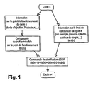
- FIG. 1 represents an exemplary embodiment of the method according to the invention.
- FIG. 1 represents the method of the invention intended to keep the noise of the motor below a maximum threshold of admissible noise.
- This method consists in controlling the noise of the engine by a function called stratification or creation of fluid strata with recycled gas rates that vary from one stratum to another.
- the combustion chamber is fed by at least two veins fluids each having a recycled gas rate regulated by the flow control means. These two fluid veins feed a combustion chamber and thus form fluid layers containing air and variable proportions of recycled gases.
- the recycled gas content of a stratum is a function of its fuel loading rate.
- Each stratum of fluid thus created has its own rate of recycled gas, and therefore its own ignition delay and its own combustion rate which allows to spread the time of combustion throughout the chamber.
- the regulation of the recycled gas rates of each stratum and the gas rate differential recycled between the strata allows the control of the combustion rate and the reduction of the combustion noise.
- the rate of combustion can be controlled by varying the difference between the two values of the recycled gas rates of each of the two fluid streams.
- the closed-loop control method of FIG. 1 consists of a first step in the noise measurement cycle n (n) emitted by the motor.
- the measurement of the engine noise can be done by any technique for detecting the rate of combustion in the chamber. To do this one can detect the time interval where the pressure inside the chamber rises abruptly. This measurement can be performed in particular using a torque sensor transmitted by the crankshaft, using a pressure sensor inside the chamber by deriving the measured signals. This measurement can also be performed using an accelerometer placed on the cylinder head or the crankshaft, looking for the maximum value of the acceleration.
- a second step of collecting information on the operating point of the engine is performed during the same time interval as the noise measurement step Brm (n).
- the operating point is primarily the amount of fuel injected for a given engine speed. Further information on the point of operation of the engine at cycle n can also be collected to determine a state of the engine.
- the amount of fuel consumed is measured directly with a flowmeter and / or indirectly using the control time of the injector and the fuel pressure injected.
- the amount of fuel calculated by indirect measurement can be corrected according to the fuel temperature and / or the pressure inside the chamber.
- a map database is used as a reference to indicate which is the mapped maximum allowable motor noise Brc (n) corresponding to a state of the engine measured at cycle n.
- the calculator then compares the maximum permissible noise Brc (n) for the operating point motor at cycle n with motor noise measured Brm (n) for this same cycle n.
- the computer increases the new stratification control value Str (n + 1) for the next cycle n + 1 relative to the value of the stratification command Str (n) of cycle n.
- the computer reduces the new stratification control value Str (n + 1) for the next cycle (n + 1) from to the value of the stratification command Str (n) of cycle n. Reducing the value of the stratification control Str (n + 1) makes it possible to reduce the difference in concentration of recycled gas between the strata of the chamber and correspondingly to increase the rate of combustion.
- This noise control method can then be repeated for subsequent motor cycles.
- the measurement time interval preferably corresponds to an integer number of motor cycles and the measurement is preferably averaged over several engine cycles in order to smooth the measurement results.
- the stratification control of this process can be based on a single cycle n, or on an average of several cycles.
- Stratification command Str (n + 1) or first recycled gas flow control signal can also be corrected using a mapped Q correction function.
- this correction function Q takes into account the sensitivity and the response time of the engine to the lamination signal to reduce the noise of the engine.
- the command can be applied to the cycle immediately following the measurement or the measurements, or be delayed several cycles. It can also apply room to room or on a set of rooms.
- the stratification function can be an all or nothing function or be a continuous variable function in proportion to the difference between the measured noise Brm (n) and the mapped noise Brc (n).
- the flow rate of gases recycled to the chamber may also be a parameter managed by a second control method such as a method for managing the overall rate of recycled gases in the chamber.
- a second control method such as a method for managing the overall rate of recycled gases in the chamber.
- the processes can give contradictory gas flow control commands commands to each other.
- FIGS. 2 and 3 respectively represent two examples of motors 30 and 60 equipped with circuits for controlling the recycling of burnt gases for the implementation of the method previously described.
- Each of these motors 30, 60 has three cylinders or combustion chambers 31, 32, 33.
- Each chamber 31, 32, 33 comprises a fuel injector 51, 52, 53 and two inlet inlets 34 to 39 respectively, separated from each other to introduce into each chamber two separate fluid veins.
- Each fluid stream may have a variable proportion of recycled flue gas over time to form gas strata in the chamber.
- the first, second and third combustion chambers 31, 32, 33 each have first and second exhaust gas exhaust outlets 50 and 43 to 48, respectively. All of these exhaust outlets 43 to 48 are connected to a main exhaust outlet 49.
- Each of the motors 30, 60 of Figures 2 and 3 is provided with a turbo 57 and a recycling means for collecting a portion of the exhaust gas 50 to introduce them at the intake.
- the intake inlets 34 to 39 of the engine 30 of FIG. 2 are connected to a main inlet 40 for the admission of air 41 and recycled flue gases 42.
- the main inlet 40 is itself connected to the main exhaust outlet 49 via a flue gas recycling means 58.
- the recycling means 30 comprises a control valve 59 for the recycled flue gas rate in the main inlet 40.
- This valve 59 thus makes it possible to control the flue gas flow rate for all the intake inlets 34 to 39 and combustion chambers 31 to 33 and this by a single means of flow control.
- First, second and third laminating valves 54 to 56 respectively connect the flue gas recycling means 58 to the second intake inlets 35, 37, and 39. Each of these three lamination valves 54 to 56 individually controls the lamination of each of the respective chambers 31 to 33.
- the first stratification valve 54 allows the admission of recycled gases into the fluid stream passing through the second intake inlet.
- the fluid stream passing through the second inlet 35 thus has a variable recycled gas content controlled by the first stratification control valve 54 and / or the rate control valve 59.
- the fluid stream passing through the first inlet 34 has a variable recycled gas rate that is controlled solely by the rate control valve 59.
- the differential concentration of recycled gas in the first chamber 31 can therefore be adjusted by acting on the first stratification valve 54.
- the engine 60 of FIG. 3 allows simultaneous and centralized control for all the chambers of the recycled gas flow and their stratifications.
- the motor 60 of this figure has first and second main intake ports 61 and 62.
- the first and second main intake inlets 61 and 62 are connected to the main exhaust outlet 49 via a first recycling means 63 for the first main entrance 61 and a second recycling means 64 for the second main entrance 62.
- the first main entrance 61 is connected to the first intake inlets 34, 36, 38 thus allowing the admission of first fluid streams having the same concentration ratio of recycled gas.
- the second main inlet 62 is connected to the second intake inlets 35, 37, 39 thus allowing the admission of second fluid streams having the same concentration ratio of recycled gas.
- the respective recycled gas flows of the first and second main inlet ports 61 and 62 are independently and respectively controlled by first and second valves 65 and 66.
- This particular installation makes it possible to control the rate of recycled gas in all the rooms by two valves. These two valves also make it possible to control the stratification by varying the recycled gas flow differential 42 passing through the first and second recycling means 63 and 64.
- the means for controlling the flow rate of the recycled exhaust gases consist of valves controlled by at least one pneumatic, hydraulic or electrical control means. These valves can deliver a continuous or discontinuous gas flow.
Landscapes
- Engineering & Computer Science (AREA)
- Chemical & Material Sciences (AREA)
- Combustion & Propulsion (AREA)
- Mechanical Engineering (AREA)
- General Engineering & Computer Science (AREA)
- Output Control And Ontrol Of Special Type Engine (AREA)
- Exhaust-Gas Circulating Devices (AREA)
- Electrical Control Of Air Or Fuel Supplied To Internal-Combustion Engine (AREA)
- Combined Controls Of Internal Combustion Engines (AREA)
- Electrical Control Of Ignition Timing (AREA)
Claims (10)
- Verfahren zum Steuern eines Verbrennungsmotors mit zyklischem Betrieb (30), wie zum Beispiel eines Dieselmotors mit Direkteinspritzung, der insbesondere Folgendes aufweist:eine Brennkammer (31),Mittel zum Einspritzen von Kraftstoff (51) in die Kammer,Einlassmittel (34, 35), um in die Kammer selektiv einen gasförmigen Sauerstoffträger einzulassen, der Luft (41) enthält, in Form einer ersten Fluidzunge,Auslassmittel (43, 44), um selektiv das Austreten verbrannter Gase (50) aus der Kammer (31) zu gestatten undRückführmittel (58), die Folgendes aufweisen:wobei das Verfahren dadurch gekennzeichnet ist, dass es ferner einen Schritt des Bestimmens des Betriebszustands des Motors aufweist, der darin besteht, mindestens die Kraftstofflast des Motors zu messen, und einen Schritt des Messens des Motorgeräuschs Brml(n), wobei diese zwei Schritte über eine erste Zeitspanne (n) ablaufen, einen Schritt des Lesens der vorgespeicherten kartografischen Datenbank, die für jeden bestimmten Betriebszustand einen maximalen zulässigen Geräuschpegel Brc(n) angibt, wobei das Verfahren ferner einen Schritt des Schichtungssteuerns aufweist, der darin besteht, in der Brennkammer und während einer zweiten Zeitspanne (n+1) nach der ersten mindestens zwei Schichten Gas zu schaffen, die jeweils unterschiedliche Konzentrationsraten an zurückgeführten Gasen haben, so dass das gemessene Motorgeräusch Brml(n) geringer als das maximal zulässige Geräusch Brc(n) bleibt oder wird.ein erstes Mittel zum Durchflusssteuern (59, 60) um verbrannte Gase (42) in der ersten Fluidzunge gemäß einer ersten Konzentrationsrate an verbrannten Gasen zurückzuführen, wobei dieses erste Durchflusssteuermittel von einem ersten Durchflusssteuersignal gesteuert wird,eine kartografische Datenbank,
- Verfahren nach dem vorhergehenden Anspruch, dadurch gekennzeichnet, dass die Schritte des Bestimmens des Betriebszustands des Motors, des Messens des Motorgeräuschs über eine Zeitspanne mehrerer Motorzyklen ausgeführt werden, so dass das Durchflusssteuersignal einer mittleren Messung von Motorgeräuschen sowie einem Bestimmen eines mittleren Motorbetriebszustands entspricht.
- Verfahren nach einem der vorhergehenden Ansprüche, dadurch gekennzeichnet, dass das erste Durchflusssteuersignal, das bei dem Schritt des Schichtungssteuerns gesendet wird, während der ganzen zweiten Zeitspanne einen gleich bleibenden mittleren Wert hat.
- Verfahren nach einem der vorhergehenden Ansprüche, dadurch gekennzeichnet, dass die Einlassmittel erste und zweite Einlasseingänge für gasförmigen Sauerstoffträger in die Kammer aufweisen, die das jeweilige Einlassen in die Kammer einer ersten und einer zweiten Fluidzunge aus gasförmigen Sauerstoffträgern gestatten.
- Verfahren nach einem der vorhergehenden Ansprüche, dadurch gekennzeichnet, dass das Rückführmittel (58) ein zweites Durchflusssteuermittel (54) für rückgeführte Gase aufweist, so dass in die Kammer (31) eine zweite Fluidzunge eingelassen wird, die eine zweite variable und kontrollierte Rate an rückgeführten Gasen hat.
- Verfahren nach einem der vorhergehenden Ansprüche, dadurch gekennzeichnet, dass jeder Zyklus des Motors eine Einlassphase aufweist, während welcher der Durchfluss an eingelassenen zurückgeführten Gasen so variabel ist, dass mehrere Sauerstoffträgergasschichten gebildet werden, die jeweils eine zeitlich variable Konzentrationsrate an rückgeführten Gasen haben.
- Verfahren nach einem der vorhergehenden Ansprüche, dadurch gekennzeichnet, dass das Messen der Motorlast an Kraftstoff von einem Durchflussmesser oder einem Mittel zum Messen der Kraftstoffeinspritzdauer ausgeführt wird.
- Verfahren nach einem der vorhergehenden Ansprüche, dadurch gekennzeichnet, dass der Motor Mittel zum Messen des Geräuschs aufweist, die ein Gasdrucksensor in der Kammer und/oder ein Sensor des Motordrehmoments und/oder ein Beschleunigungsmesser sein können.
- Verfahren nach einem der vorhergehenden Ansprüche, dadurch gekennzeichnet, dass die Rückführmittel Schieber aufweisen, die von mindestens einem pneumatischen, hydraulischen oder elektrischen Steuermittel gesteuert werden.
- Verfahren nach einem der vorhergehenden Ansprüche, dadurch gekennzeichnet, dass das erste Durchflusssteuersignal eine variable Funktion des Unterschieds zwischen dem gemessenen Geräusch Brm(n) und dem kartografierten Geräusch Brc(n) ist.
Applications Claiming Priority (2)
| Application Number | Priority Date | Filing Date | Title |
|---|---|---|---|
| FR0305579A FR2854656B1 (fr) | 2003-05-07 | 2003-05-07 | Procede de pilotage de bruit d'un moteur thermique |
| PCT/FR2004/001119 WO2004099590A2 (fr) | 2003-05-07 | 2004-05-07 | Procede de pilotage de bruit d’un moteur thermique |
Publications (2)
| Publication Number | Publication Date |
|---|---|
| EP1627140A2 EP1627140A2 (de) | 2006-02-22 |
| EP1627140B1 true EP1627140B1 (de) | 2007-02-28 |
Family
ID=33306225
Family Applications (1)
| Application Number | Title | Priority Date | Filing Date |
|---|---|---|---|
| EP04742677A Expired - Lifetime EP1627140B1 (de) | 2003-05-07 | 2004-05-07 | Verfahren zur geräuschansteuerung einer brennkraftmaschine |
Country Status (6)
| Country | Link |
|---|---|
| EP (1) | EP1627140B1 (de) |
| JP (1) | JP4854505B2 (de) |
| AT (1) | ATE355448T1 (de) |
| DE (1) | DE602004005034T2 (de) |
| FR (1) | FR2854656B1 (de) |
| WO (1) | WO2004099590A2 (de) |
Families Citing this family (4)
| Publication number | Priority date | Publication date | Assignee | Title |
|---|---|---|---|---|
| FR2890112B1 (fr) * | 2005-08-30 | 2007-11-30 | Peugeot Citroen Automobiles Sa | Systeme de controle du fonctionnement d'un moteur diesel de vehicule automobile equipe de moyens de recirculation de gaz d'echappement |
| FR2929994B1 (fr) * | 2008-04-11 | 2012-04-20 | Renault Sas | Dispositif de controle du bruit emis par un moteur a combustion interne. |
| FR2950111B1 (fr) * | 2009-09-15 | 2011-09-09 | Renault Sa | Procede de commande d'un moteur diesel suralimente a recirculation de gaz d'echappement a basse pression |
| CN114856839B (zh) * | 2022-05-10 | 2023-04-07 | 西安交通大学 | 一种组合燃料发动机燃油品质检测调节装置及方法 |
Family Cites Families (5)
| Publication number | Priority date | Publication date | Assignee | Title |
|---|---|---|---|---|
| FR2768180B1 (fr) * | 1997-09-09 | 1999-10-08 | Inst Francais Du Petrole | Procede de fonctionnement d'un moteur 4 temps, en auto-allumage controle |
| JP3607983B2 (ja) * | 1999-09-10 | 2005-01-05 | トヨタ自動車株式会社 | 内燃機関の燃焼制御装置 |
| JP3767352B2 (ja) * | 2000-09-18 | 2006-04-19 | トヨタ自動車株式会社 | 内燃機関の制御装置 |
| US6612292B2 (en) * | 2001-01-09 | 2003-09-02 | Nissan Motor Co., Ltd. | Fuel injection control for diesel engine |
| JP2002349335A (ja) * | 2001-03-21 | 2002-12-04 | Mazda Motor Corp | 筒内噴射式エンジンの制御装置 |
-
2003
- 2003-05-07 FR FR0305579A patent/FR2854656B1/fr not_active Expired - Fee Related
-
2004
- 2004-05-07 EP EP04742677A patent/EP1627140B1/de not_active Expired - Lifetime
- 2004-05-07 AT AT04742677T patent/ATE355448T1/de not_active IP Right Cessation
- 2004-05-07 DE DE602004005034T patent/DE602004005034T2/de not_active Expired - Lifetime
- 2004-05-07 WO PCT/FR2004/001119 patent/WO2004099590A2/fr not_active Ceased
- 2004-05-07 JP JP2006505835A patent/JP4854505B2/ja not_active Expired - Fee Related
Also Published As
| Publication number | Publication date |
|---|---|
| FR2854656A1 (fr) | 2004-11-12 |
| DE602004005034D1 (de) | 2007-04-12 |
| WO2004099590A2 (fr) | 2004-11-18 |
| ATE355448T1 (de) | 2006-03-15 |
| WO2004099590A3 (fr) | 2005-01-13 |
| JP2006525464A (ja) | 2006-11-09 |
| EP1627140A2 (de) | 2006-02-22 |
| DE602004005034T2 (de) | 2007-10-31 |
| JP4854505B2 (ja) | 2012-01-18 |
| FR2854656B1 (fr) | 2005-08-05 |
Similar Documents
| Publication | Publication Date | Title |
|---|---|---|
| EP2581590B1 (de) | Verfahren zur steuerung eines abgasrückführventils | |
| FR2785332A1 (fr) | Procede et dispositif pour determiner le couple d'un moteur a combustion interne a injection directe d'essence | |
| EP2361349B1 (de) | Verfahren zur dynamischen schätzung der frischluftdurchflussrate, die einem motor mit hochdruck- und niederdruck-agr-kreisen zugeführt wird. | |
| CN102787924A (zh) | 基于燃料后喷射量评估的生物柴油混合检测的方法 | |
| FR2942003A1 (fr) | Moteur a combustion interne du type diesel suralimente et procede de commande du debit d'air dans un tel moteur | |
| EP2581589A1 (de) | Kontrollverfahren eines Verbrennungsmotors mit Hilfe der Abschätzung der Massenfraktion des im Ansaugrohr verbrannten Gases | |
| EP1627140B1 (de) | Verfahren zur geräuschansteuerung einer brennkraftmaschine | |
| FR2758590A1 (fr) | Dispositif de commande d'un moteur a combustion interne a allumage commande et injection directe | |
| FR2947007A1 (fr) | Procede et systeme de commande d'un moteur avec estimation dynamique du debit d'air frais d'alimentation. | |
| WO2010130937A1 (fr) | Estimation de la concentration en oxydes d ' azote d ' un moteur a combustion interne | |
| EP1629185B1 (de) | Steuerverfahren einer brennkraftmaschine | |
| FR2923544A1 (fr) | Moteur a combustion interne du type diesel suralimente et procede de commande du debit d'air et du taux de gaz d'echappement recycle dans un tel moteur | |
| FR3132546A1 (fr) | Procédé de contrôle du débit dans un conduit de recirculation partielle de gaz d’échappement à l’admission d’un moteur et dispositif associé | |
| WO2021078998A1 (fr) | Procédé de régulation d'une pression dans un système d'injection d'eau pour un moteur à combustion interne | |
| EP1650420B1 (de) | Vorrichtung und Verfahren zur Regelung der Partikelfilterregeneration einer Brennkraftmaschine | |
| FR3034143A1 (fr) | Dispositif comportant un circuit de recirculation de gaz d'echappement | |
| EP2184597A1 (de) | Verfahren zur Verbrennungskontrolle eines Motors, der im Schichtmodus funktioniert | |
| EP2946098A1 (de) | System zur behandlung von abgasen eines kraftfahrzeuges und verfahren zur steuerung davon | |
| FR2945319A1 (fr) | Systeme et procede de commande de la combustion dans un moteur a combustion interne. | |
| FR2903735A1 (fr) | Systeme de commande d'un moteur a combustion du type diesel suralimente avec recirculation des gaz d'echappement | |
| FR3082887A1 (fr) | Procede de determination d’une consigne de puissance d’un compresseur de moteur a combustion interne | |
| EP4234909A1 (de) | Verfahren zur steuerung des gemischverhältnisses des kraftstoffgemischs einer brennkraftmaschine eines kraftfahrzeugs | |
| WO2006070146A1 (fr) | Procede et systeme de commande d'un moteur diesel a richesse 1 | |
| FR3114619A1 (fr) | Procédé de détermination de la masse de gaz aspiré dans un cylindre avec prise en compte des conditions réelles d’utilisation | |
| EP1544445A1 (de) | Prozess und Einrichtung zur Regelung der Funktion des Verbrennungsmotors eines Kraftfahrzeugs |
Legal Events
| Date | Code | Title | Description |
|---|---|---|---|
| PUAI | Public reference made under article 153(3) epc to a published international application that has entered the european phase |
Free format text: ORIGINAL CODE: 0009012 |
|
| 17P | Request for examination filed |
Effective date: 20051024 |
|
| AK | Designated contracting states |
Kind code of ref document: A2 Designated state(s): AT BE BG CH CY CZ DE DK EE ES FI FR GB GR HU IE IT LI LU MC NL PL PT RO SE SI SK TR |
|
| DAX | Request for extension of the european patent (deleted) | ||
| GRAP | Despatch of communication of intention to grant a patent |
Free format text: ORIGINAL CODE: EPIDOSNIGR1 |
|
| GRAS | Grant fee paid |
Free format text: ORIGINAL CODE: EPIDOSNIGR3 |
|
| GRAA | (expected) grant |
Free format text: ORIGINAL CODE: 0009210 |
|
| AK | Designated contracting states |
Kind code of ref document: B1 Designated state(s): AT BE BG CH CY CZ DE DK EE ES FI FR GB GR HU IE IT LI LU MC NL PL PT RO SE SI SK TR |
|
| PG25 | Lapsed in a contracting state [announced via postgrant information from national office to epo] |
Ref country code: FI Free format text: LAPSE BECAUSE OF FAILURE TO SUBMIT A TRANSLATION OF THE DESCRIPTION OR TO PAY THE FEE WITHIN THE PRESCRIBED TIME-LIMIT Effective date: 20070228 Ref country code: SI Free format text: LAPSE BECAUSE OF FAILURE TO SUBMIT A TRANSLATION OF THE DESCRIPTION OR TO PAY THE FEE WITHIN THE PRESCRIBED TIME-LIMIT Effective date: 20070228 Ref country code: DK Free format text: LAPSE BECAUSE OF FAILURE TO SUBMIT A TRANSLATION OF THE DESCRIPTION OR TO PAY THE FEE WITHIN THE PRESCRIBED TIME-LIMIT Effective date: 20070228 Ref country code: PL Free format text: LAPSE BECAUSE OF FAILURE TO SUBMIT A TRANSLATION OF THE DESCRIPTION OR TO PAY THE FEE WITHIN THE PRESCRIBED TIME-LIMIT Effective date: 20070228 Ref country code: NL Free format text: LAPSE BECAUSE OF FAILURE TO SUBMIT A TRANSLATION OF THE DESCRIPTION OR TO PAY THE FEE WITHIN THE PRESCRIBED TIME-LIMIT Effective date: 20070228 Ref country code: AT Free format text: LAPSE BECAUSE OF FAILURE TO SUBMIT A TRANSLATION OF THE DESCRIPTION OR TO PAY THE FEE WITHIN THE PRESCRIBED TIME-LIMIT Effective date: 20070228 |
|
| REG | Reference to a national code |
Ref country code: GB Ref legal event code: FG4D Free format text: NOT ENGLISH |
|
| REG | Reference to a national code |
Ref country code: CH Ref legal event code: EP |
|
| REF | Corresponds to: |
Ref document number: 602004005034 Country of ref document: DE Date of ref document: 20070412 Kind code of ref document: P |
|
| REG | Reference to a national code |
Ref country code: IE Ref legal event code: FG4D Free format text: LANGUAGE OF EP DOCUMENT: FRENCH |
|
| PG25 | Lapsed in a contracting state [announced via postgrant information from national office to epo] |
Ref country code: BG Free format text: LAPSE BECAUSE OF FAILURE TO SUBMIT A TRANSLATION OF THE DESCRIPTION OR TO PAY THE FEE WITHIN THE PRESCRIBED TIME-LIMIT Effective date: 20070528 |
|
| PG25 | Lapsed in a contracting state [announced via postgrant information from national office to epo] |
Ref country code: SE Free format text: LAPSE BECAUSE OF FAILURE TO SUBMIT A TRANSLATION OF THE DESCRIPTION OR TO PAY THE FEE WITHIN THE PRESCRIBED TIME-LIMIT Effective date: 20070531 |
|
| PG25 | Lapsed in a contracting state [announced via postgrant information from national office to epo] |
Ref country code: ES Free format text: LAPSE BECAUSE OF FAILURE TO SUBMIT A TRANSLATION OF THE DESCRIPTION OR TO PAY THE FEE WITHIN THE PRESCRIBED TIME-LIMIT Effective date: 20070608 |
|
| PG25 | Lapsed in a contracting state [announced via postgrant information from national office to epo] |
Ref country code: PT Free format text: LAPSE BECAUSE OF FAILURE TO SUBMIT A TRANSLATION OF THE DESCRIPTION OR TO PAY THE FEE WITHIN THE PRESCRIBED TIME-LIMIT Effective date: 20070730 |
|
| NLV1 | Nl: lapsed or annulled due to failure to fulfill the requirements of art. 29p and 29m of the patents act | ||
| GBV | Gb: ep patent (uk) treated as always having been void in accordance with gb section 77(7)/1977 [no translation filed] |
Effective date: 20070228 |
|
| PG25 | Lapsed in a contracting state [announced via postgrant information from national office to epo] |
Ref country code: SK Free format text: LAPSE BECAUSE OF FAILURE TO SUBMIT A TRANSLATION OF THE DESCRIPTION OR TO PAY THE FEE WITHIN THE PRESCRIBED TIME-LIMIT Effective date: 20070228 Ref country code: GB Free format text: LAPSE BECAUSE OF FAILURE TO SUBMIT A TRANSLATION OF THE DESCRIPTION OR TO PAY THE FEE WITHIN THE PRESCRIBED TIME-LIMIT Effective date: 20070228 |
|
| REG | Reference to a national code |
Ref country code: IE Ref legal event code: FD4D |
|
| BERE | Be: lapsed |
Owner name: RENAULT S.A.S. Effective date: 20070531 |
|
| PG25 | Lapsed in a contracting state [announced via postgrant information from national office to epo] |
Ref country code: RO Free format text: LAPSE BECAUSE OF FAILURE TO SUBMIT A TRANSLATION OF THE DESCRIPTION OR TO PAY THE FEE WITHIN THE PRESCRIBED TIME-LIMIT Effective date: 20070228 Ref country code: CZ Free format text: LAPSE BECAUSE OF FAILURE TO SUBMIT A TRANSLATION OF THE DESCRIPTION OR TO PAY THE FEE WITHIN THE PRESCRIBED TIME-LIMIT Effective date: 20070228 |
|
| PLBE | No opposition filed within time limit |
Free format text: ORIGINAL CODE: 0009261 |
|
| STAA | Information on the status of an ep patent application or granted ep patent |
Free format text: STATUS: NO OPPOSITION FILED WITHIN TIME LIMIT |
|
| PG25 | Lapsed in a contracting state [announced via postgrant information from national office to epo] |
Ref country code: MC Free format text: LAPSE BECAUSE OF NON-PAYMENT OF DUE FEES Effective date: 20070531 Ref country code: IE Free format text: LAPSE BECAUSE OF FAILURE TO SUBMIT A TRANSLATION OF THE DESCRIPTION OR TO PAY THE FEE WITHIN THE PRESCRIBED TIME-LIMIT Effective date: 20070228 |
|
| 26N | No opposition filed |
Effective date: 20071129 |
|
| REG | Reference to a national code |
Ref country code: FR Ref legal event code: ST Effective date: 20080131 |
|
| PG25 | Lapsed in a contracting state [announced via postgrant information from national office to epo] |
Ref country code: BE Free format text: LAPSE BECAUSE OF NON-PAYMENT OF DUE FEES Effective date: 20070531 |
|
| PG25 | Lapsed in a contracting state [announced via postgrant information from national office to epo] |
Ref country code: GR Free format text: LAPSE BECAUSE OF FAILURE TO SUBMIT A TRANSLATION OF THE DESCRIPTION OR TO PAY THE FEE WITHIN THE PRESCRIBED TIME-LIMIT Effective date: 20070529 Ref country code: IT Free format text: LAPSE BECAUSE OF FAILURE TO SUBMIT A TRANSLATION OF THE DESCRIPTION OR TO PAY THE FEE WITHIN THE PRESCRIBED TIME-LIMIT Effective date: 20070228 |
|
| PG25 | Lapsed in a contracting state [announced via postgrant information from national office to epo] |
Ref country code: FR Free format text: LAPSE BECAUSE OF NON-PAYMENT OF DUE FEES Effective date: 20070531 |
|
| REG | Reference to a national code |
Ref country code: CH Ref legal event code: PL |
|
| PG25 | Lapsed in a contracting state [announced via postgrant information from national office to epo] |
Ref country code: LI Free format text: LAPSE BECAUSE OF NON-PAYMENT OF DUE FEES Effective date: 20080531 Ref country code: EE Free format text: LAPSE BECAUSE OF FAILURE TO SUBMIT A TRANSLATION OF THE DESCRIPTION OR TO PAY THE FEE WITHIN THE PRESCRIBED TIME-LIMIT Effective date: 20070228 Ref country code: CH Free format text: LAPSE BECAUSE OF NON-PAYMENT OF DUE FEES Effective date: 20080531 |
|
| PG25 | Lapsed in a contracting state [announced via postgrant information from national office to epo] |
Ref country code: CY Free format text: LAPSE BECAUSE OF FAILURE TO SUBMIT A TRANSLATION OF THE DESCRIPTION OR TO PAY THE FEE WITHIN THE PRESCRIBED TIME-LIMIT Effective date: 20070228 |
|
| PG25 | Lapsed in a contracting state [announced via postgrant information from national office to epo] |
Ref country code: LU Free format text: LAPSE BECAUSE OF NON-PAYMENT OF DUE FEES Effective date: 20070507 |
|
| PG25 | Lapsed in a contracting state [announced via postgrant information from national office to epo] |
Ref country code: HU Free format text: LAPSE BECAUSE OF FAILURE TO SUBMIT A TRANSLATION OF THE DESCRIPTION OR TO PAY THE FEE WITHIN THE PRESCRIBED TIME-LIMIT Effective date: 20070901 Ref country code: TR Free format text: LAPSE BECAUSE OF FAILURE TO SUBMIT A TRANSLATION OF THE DESCRIPTION OR TO PAY THE FEE WITHIN THE PRESCRIBED TIME-LIMIT Effective date: 20070228 |
|
| PGFP | Annual fee paid to national office [announced via postgrant information from national office to epo] |
Ref country code: DE Payment date: 20150521 Year of fee payment: 12 |
|
| REG | Reference to a national code |
Ref country code: DE Ref legal event code: R119 Ref document number: 602004005034 Country of ref document: DE |
|
| PG25 | Lapsed in a contracting state [announced via postgrant information from national office to epo] |
Ref country code: DE Free format text: LAPSE BECAUSE OF NON-PAYMENT OF DUE FEES Effective date: 20161201 |