EP2172720B1 - Temperature control system with a directly-controlled purge cycle - Google Patents
Temperature control system with a directly-controlled purge cycle Download PDFInfo
- Publication number
- EP2172720B1 EP2172720B1 EP09252326A EP09252326A EP2172720B1 EP 2172720 B1 EP2172720 B1 EP 2172720B1 EP 09252326 A EP09252326 A EP 09252326A EP 09252326 A EP09252326 A EP 09252326A EP 2172720 B1 EP2172720 B1 EP 2172720B1
- Authority
- EP
- European Patent Office
- Prior art keywords
- heat exchanger
- compressor
- control system
- accumulator
- temperature control
- Prior art date
- Legal status (The legal status is an assumption and is not a legal conclusion. Google has not performed a legal analysis and makes no representation as to the accuracy of the status listed.)
- Active
Links
Images

Classifications
-
- F—MECHANICAL ENGINEERING; LIGHTING; HEATING; WEAPONS; BLASTING
- F25—REFRIGERATION OR COOLING; COMBINED HEATING AND REFRIGERATION SYSTEMS; HEAT PUMP SYSTEMS; MANUFACTURE OR STORAGE OF ICE; LIQUEFACTION SOLIDIFICATION OF GASES
- F25B—REFRIGERATION MACHINES, PLANTS OR SYSTEMS; COMBINED HEATING AND REFRIGERATION SYSTEMS; HEAT PUMP SYSTEMS
- F25B13/00—Compression machines, plants or systems, with reversible cycle
-
- F—MECHANICAL ENGINEERING; LIGHTING; HEATING; WEAPONS; BLASTING
- F25—REFRIGERATION OR COOLING; COMBINED HEATING AND REFRIGERATION SYSTEMS; HEAT PUMP SYSTEMS; MANUFACTURE OR STORAGE OF ICE; LIQUEFACTION SOLIDIFICATION OF GASES
- F25B—REFRIGERATION MACHINES, PLANTS OR SYSTEMS; COMBINED HEATING AND REFRIGERATION SYSTEMS; HEAT PUMP SYSTEMS
- F25B43/00—Arrangements for separating or purifying gases or liquids; Arrangements for vaporising the residuum of liquid refrigerant, e.g. by heat
- F25B43/006—Accumulators
-
- F—MECHANICAL ENGINEERING; LIGHTING; HEATING; WEAPONS; BLASTING
- F25—REFRIGERATION OR COOLING; COMBINED HEATING AND REFRIGERATION SYSTEMS; HEAT PUMP SYSTEMS; MANUFACTURE OR STORAGE OF ICE; LIQUEFACTION SOLIDIFICATION OF GASES
- F25B—REFRIGERATION MACHINES, PLANTS OR SYSTEMS; COMBINED HEATING AND REFRIGERATION SYSTEMS; HEAT PUMP SYSTEMS
- F25B47/00—Arrangements for preventing or removing deposits or corrosion, not provided for in another subclass
- F25B47/02—Defrosting cycles
- F25B47/022—Defrosting cycles hot gas defrosting
- F25B47/025—Defrosting cycles hot gas defrosting by reversing the cycle
-
- F—MECHANICAL ENGINEERING; LIGHTING; HEATING; WEAPONS; BLASTING
- F25—REFRIGERATION OR COOLING; COMBINED HEATING AND REFRIGERATION SYSTEMS; HEAT PUMP SYSTEMS; MANUFACTURE OR STORAGE OF ICE; LIQUEFACTION SOLIDIFICATION OF GASES
- F25B—REFRIGERATION MACHINES, PLANTS OR SYSTEMS; COMBINED HEATING AND REFRIGERATION SYSTEMS; HEAT PUMP SYSTEMS
- F25B2313/00—Compression machines, plants or systems with reversible cycle not otherwise provided for
- F25B2313/007—Compression machines, plants or systems with reversible cycle not otherwise provided for three pipes connecting the outdoor side to the indoor side with multiple indoor units
-
- F—MECHANICAL ENGINEERING; LIGHTING; HEATING; WEAPONS; BLASTING
- F25—REFRIGERATION OR COOLING; COMBINED HEATING AND REFRIGERATION SYSTEMS; HEAT PUMP SYSTEMS; MANUFACTURE OR STORAGE OF ICE; LIQUEFACTION SOLIDIFICATION OF GASES
- F25B—REFRIGERATION MACHINES, PLANTS OR SYSTEMS; COMBINED HEATING AND REFRIGERATION SYSTEMS; HEAT PUMP SYSTEMS
- F25B2313/00—Compression machines, plants or systems with reversible cycle not otherwise provided for
- F25B2313/027—Compression machines, plants or systems with reversible cycle not otherwise provided for characterised by the reversing means
- F25B2313/02731—Compression machines, plants or systems with reversible cycle not otherwise provided for characterised by the reversing means using one three-way valve
-
- F—MECHANICAL ENGINEERING; LIGHTING; HEATING; WEAPONS; BLASTING
- F25—REFRIGERATION OR COOLING; COMBINED HEATING AND REFRIGERATION SYSTEMS; HEAT PUMP SYSTEMS; MANUFACTURE OR STORAGE OF ICE; LIQUEFACTION SOLIDIFICATION OF GASES
- F25B—REFRIGERATION MACHINES, PLANTS OR SYSTEMS; COMBINED HEATING AND REFRIGERATION SYSTEMS; HEAT PUMP SYSTEMS
- F25B2313/00—Compression machines, plants or systems with reversible cycle not otherwise provided for
- F25B2313/029—Control issues
- F25B2313/0292—Control issues related to reversing valves
-
- F—MECHANICAL ENGINEERING; LIGHTING; HEATING; WEAPONS; BLASTING
- F25—REFRIGERATION OR COOLING; COMBINED HEATING AND REFRIGERATION SYSTEMS; HEAT PUMP SYSTEMS; MANUFACTURE OR STORAGE OF ICE; LIQUEFACTION SOLIDIFICATION OF GASES
- F25B—REFRIGERATION MACHINES, PLANTS OR SYSTEMS; COMBINED HEATING AND REFRIGERATION SYSTEMS; HEAT PUMP SYSTEMS
- F25B2400/00—Component parts or details not otherwise provided for in this subclass
- F25B2400/04—Refrigeration circuit bypassing means
- F25B2400/0403—Refrigeration circuit bypassing means for condensers
-
- F—MECHANICAL ENGINEERING; LIGHTING; HEATING; WEAPONS; BLASTING
- F25—REFRIGERATION OR COOLING; COMBINED HEATING AND REFRIGERATION SYSTEMS; HEAT PUMP SYSTEMS; MANUFACTURE OR STORAGE OF ICE; LIQUEFACTION SOLIDIFICATION OF GASES
- F25B—REFRIGERATION MACHINES, PLANTS OR SYSTEMS; COMBINED HEATING AND REFRIGERATION SYSTEMS; HEAT PUMP SYSTEMS
- F25B2400/00—Component parts or details not otherwise provided for in this subclass
- F25B2400/04—Refrigeration circuit bypassing means
- F25B2400/0409—Refrigeration circuit bypassing means for evaporators
-
- F—MECHANICAL ENGINEERING; LIGHTING; HEATING; WEAPONS; BLASTING
- F25—REFRIGERATION OR COOLING; COMBINED HEATING AND REFRIGERATION SYSTEMS; HEAT PUMP SYSTEMS; MANUFACTURE OR STORAGE OF ICE; LIQUEFACTION SOLIDIFICATION OF GASES
- F25B—REFRIGERATION MACHINES, PLANTS OR SYSTEMS; COMBINED HEATING AND REFRIGERATION SYSTEMS; HEAT PUMP SYSTEMS
- F25B2400/00—Component parts or details not otherwise provided for in this subclass
- F25B2400/04—Refrigeration circuit bypassing means
- F25B2400/0411—Refrigeration circuit bypassing means for expansion valves or capillary tubes
-
- F—MECHANICAL ENGINEERING; LIGHTING; HEATING; WEAPONS; BLASTING
- F25—REFRIGERATION OR COOLING; COMBINED HEATING AND REFRIGERATION SYSTEMS; HEAT PUMP SYSTEMS; MANUFACTURE OR STORAGE OF ICE; LIQUEFACTION SOLIDIFICATION OF GASES
- F25B—REFRIGERATION MACHINES, PLANTS OR SYSTEMS; COMBINED HEATING AND REFRIGERATION SYSTEMS; HEAT PUMP SYSTEMS
- F25B2600/00—Control issues
- F25B2600/25—Control of valves
- F25B2600/2501—Bypass valves
-
- F—MECHANICAL ENGINEERING; LIGHTING; HEATING; WEAPONS; BLASTING
- F25—REFRIGERATION OR COOLING; COMBINED HEATING AND REFRIGERATION SYSTEMS; HEAT PUMP SYSTEMS; MANUFACTURE OR STORAGE OF ICE; LIQUEFACTION SOLIDIFICATION OF GASES
- F25B—REFRIGERATION MACHINES, PLANTS OR SYSTEMS; COMBINED HEATING AND REFRIGERATION SYSTEMS; HEAT PUMP SYSTEMS
- F25B2700/00—Sensing or detecting of parameters; Sensors therefor
- F25B2700/04—Refrigerant level
Definitions
- the present invention relates to temperature control systems. More particularly, the present invention relates to a temperature control system for a transport vehicle.
- transport vehicles e.g., straight trucks and tractor-trailer combinations
- transport vehicles e.g., straight trucks and tractor-trailer combinations
- the cargo is transported, stored, or otherwise supported within a cargo space of the transport vehicle.
- the temperature control system In some transport units, the temperature control system must be capable of cooling and heating the cargo space to maintain a desired temperature (i.e., a setpoint temperature). A controller switches the temperature control unit between heating and cooling modes based on the relative difference between a sensed temperature and the setpoint temperature to regulate the condition of the cargo space.
- the temperature control system is capable of operating a conventional refrigeration cycle utilizing a phase-change refrigerant to cool the cargo space. Refrigerant is compressed by a compressor, condensed, and evaporated in a heat exchanger in thermal communication with the cargo space to cool the cargo space. Heating is typically accomplished by bypassing the condenser and directing hot compressed refrigerant directly to the heat exchanger in thermal communication with the cargo space to heat the cargo space.
- a temperature control system comprising a compressor configured to compress a heat transfer fluid; a first heat exchanger in fluid communication with the compressor and configured to receive the heat transfer fluid from the compressor and to cool and condense the heat transfer fluid; a second heat exchanger in fluid communication with the first heat exchanger and the compressor and configured to exchange heat with a temperature-controlled space; an accumulator in fluid communication with the second heat exchanger and the compressor and configured to receive a mixture of liquid and vapor heat transfer fluid from the second heat exchanger and direct a vapor portion of the heat transfer fluid to the compressor a valve in fluid communication with the first heat exchanger, the compressor, and the second heat exchange, the valve operable in a first position and a second position, wherein the first position is operable to direct the heat transfer fluid from the compressor to the first heat exchanger and the second position is operable to direct the heat transfer fluid from the compressor to the second heat exchanger without passing through the first heat exchanger; characterised by a liquid level sensor associated with the accumulator and
- a method of operating a temperature control system comprising compressing a heat transfer fluid with a compressor; directing the heat transfer fluid from the compressor to a first heat exchanger with a valve in a first position; cooling and condensing the heat transfer fluid from the compressor in the first heat exchanger; exchanging heat with a temperature-controlled space with a second heat exchanger; receiving a mixture of liquid and vapor heat transfer fluid from the second heat exchanger into an accumulator; directing a vapor portion of the heat transfer fluid in the accumulator to the compressor; characterised by generating with a liquid level sensor associated with the accumulator a signal indicative of the level of the liquid heat transfer fluid inside the accumulator; receiving the signal with a controller, moving the valve with the controller from the first position to a second position based on the signal; and directing the heat transfer fluid from the compressor to the second heat exchanger without passing through the first heat exchanger with the valve in the second position.
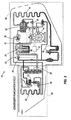
- Fig. 1 is a schematic of a temperature control system according to one embodiment of the present invention, illustrating a cooling mode.
- Fig. 2 is a schematic of the temperature control system of Fig. 1 , illustrating a condenser evacuation mode.
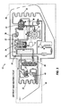
- Fig. 3 is a schematic of the temperature control system of Fig. 1 , illustrating a heating/defrost mode.
- Figs. 1-3 illustrate a temperature control system 10 for a transport vehicle.
- the temperature control system 10 is capable of cooling and heating a cargo space of the transport vehicle to maintain a desired temperature (i.e., a setpoint temperature).
- the temperature control system 10 includes a controller 12 that switches the temperature control system 10 between heating and cooling modes based on the relative difference between a sensed temperature and the setpoint temperature to regulate the condition of the cargo space.
- the refrigeration system 10 may be utilized for other refrigeration applications and is not limited to transport refrigeration applications.
- the temperature control system 10 includes a compressor 14, a first heat exchanger 16, a receiver 18, an expansion valve 20, a second heat exchanger 22 and an accumulator 24 connected in series by fluid conduits.
- the first heat exchanger 16 is in thermal communication with air outside of the transport vehicle.
- the second heat exchanger 22 is in thermal communication with air inside the cargo space of the transport vehicle. In other constructions, there may be more than one heat exchanger in thermal communication with air inside the cargo space.
- a distributor 40 may be employed, as is well known in the art, to distribute refrigerant to a plurality of second heat exchangers (not shown).
- a first portion 44 of the temperature control system 10, including the second heat exchanger 22, is preferably positioned within the cargo space.
- a second portion 46 of the temperature control system 10, including the first heat exchanger 16, is preferably positioned outside of the cargo space.
- the receiver 18 receives a heat transfer fluid (e.g., refrigerant) from the first heat exchanger 16 and directs refrigerant to the second heat exchanger 22.
- the expansion valve 20, reduces the pressure of the refrigerant just upstream of the second heat exchanger 22.
- the accumulator 24 receives a liquid and gaseous mixture of refrigerant from the second heat exchanger and includes a liquid level sensor 32 for detecting a level of liquid in the accumulator 24. Liquid refrigerant accumulates at the bottom of the accumulator 24 and gaseous refrigerant is displaced to the top.
- the accumulator 24 includes a U-tube 42 (i.e., a U-shaped tube) for drawing gaseous refrigerant from the top of the accumulator 24 into the compressor suction line, as is well known in the art.
- the liquid level must remain below the inlet of the U-tube 42 in order to prevent the liquid from entering the compressor suction line.
- the liquid level sensor 32 is positioned at an optimum height within the accumulator tank. The optimum height is chosen such that a liquid level at or below the optimum height is unlikely to result in liquid entering the compressor 14 during movement of the transport vehicle and operation of the temperature control system 10. In other constructions, such as non-transport applications, the optimum height may be closer to the top of the U-tube 42 since movement of the liquid is not expected. Furthermore, the optimum height ensures that an adequate amount of refrigerant is available during a heating/defrost mode of operation, which will be explained in further detail below.
- the liquid level sensor 32 generates a first signal indicative of a refrigerant level below the optimal level and a second signal indicative of a refrigerant level at or above the optimal level.
- the sensor 32 may generate an output when the level is below the optimal level (i.e., generate a voltage output value) and not generate any output (i.e., voltage) when the level is at or above the optimal level.
- the lack of an output which can be recognized by the controller 12 as indicative of a liquid level at or above the optimal level, should be considered to be the generation of a signal indicative of the refrigerant level.
- the liquid level sensor can be a float device, a hydrostatic device, a load cell, a magnetic level gauge, a capacitance transmitter, a magnetostrictive level transmitter, an ultrasonic level transmitter, a laser level transmitter, a radar level transmitter, or the like.
- the temperature control system 10 also includes a suction line heat exchanger 26 and a purge valve 28.
- the suction line heat exchanger 26 is a shell and tube heat exchanger that transfers heat between the warm liquid refrigerant entering the second heat exchanger 22 and cold vapor refrigerant leaving the second heat exchanger 22. It is to be understood that other types of heat exchangers may be used to accomplish the same results.
- the purge valve 28 is a solenoid valve in communication with a fluid conduit 34 that fluidly connects the first heat exchanger 16 to the accumulator 24, bypassing the suction line heat exchanger 26, the expansion valve 20 and the second heat exchanger 22.
- a three-way valve 30 is operable in a first position ( Figs. 1 and 2 ) in which refrigerant is directed from the compressor 14 to the first heat exchanger 16 and a second position ( Fig. 3 ) in which refrigerant is directed from the compressor 14 to the second heat exchanger 22.
- a refrigeration or cooling circuit is formed in the first position.
- a heating/defrost circuit is formed in the second position.
- the controller 12 controls the position of the three-way valve 30 by opening and closing a pilot solenoid valve 36 in a manner well understood in the art.
- the three-way valve 30 is kept in the first position by maintaining the pilot solenoid valve 36 closed, which builds pressure to hold the valve 30 in the first position.
- the controller 12 opens the pilot solenoid valve 36, the pressure is released and the three-way valve 30 moves from the first position to the second position.
- the controller l2 closes the pilot solenoid valve 36, the pressure builds and the three-way valve 30 moves from the second position to the first position.
- other types of switching mechanisms may be employed to switch the system between a refrigeration circuit and a heating/defrost circuit.
- the temperature control system 10 is operable in a cooling mode, a condenser evacuation mode, and a heating/defrost mode.
- the controller 12 communicates with the pilot solenoid valve 36 to place the three-way valve 30 in the first position during the cooling mode and the condenser evacuation mode, and in the second position during the heating/defrost mode.
- the three-way valve is in the first position to direct high pressure gas refrigerant from the compressor to the first heat exchanger 16.
- the high pressure gas refrigerant is condensed in the first heat exchanger 16 to a high pressure liquid refrigerant, which is directed to the receiver 18.
- the receiver 18 ensures that only liquid refrigerant is directed toward the second heat exchanger 22.
- the high pressure liquid refrigerant Prior to the high pressure liquid refrigerant entering the second heat exchanger 22, the high pressure liquid refrigerant enters the suction line heat exchanger 26 to be pre-cooled by low pressure refrigerant exiting the second heat exchanger 22. Then, the high pressure liquid refrigerant is passed through an expansion valve 20 to lower the pressure of the refrigerant.
- At least a portion of the refrigerant evaporates in the second heat exchanger 22 to create a mixture of low pressure liquid and low pressure gas.
- the mixture passes through the second heat exchanger 22 and absorbs heat from air being directed into the cargo space to thereby cool the cargo space.
- the mixture then passes through the suction line heat exchanger 26 and exchanges heat with the high pressure liquid refrigerant approaching the second heat exchanger 22.
- the mixture is separated in the accumulator 24 in which low pressure liquid refrigerant is collected at the bottom and low pressure gas refrigerant is drawn from the top into the compressor suction line via the U-tube 42.
- the controller 12 ensures that the purge valve 28 is closed to prevent the movement of high pressure liquid refrigerant into the accumulator 24.
- the temperature control system 10 remains in the cooling mode until a heating or defrost operation is needed. When a heating or defrost operation is needed, the controller switches to the condenser evacuation mode.
- the condenser evacuation mode is operated between the cooling and heating/defrost modes to move an optimal amount of refrigerant from the high pressure side to the low pressure side for use during the heating/defrost mode.
- the three-way valve 30 is in the first position.
- the controller 12 opens the purge valve 28 to allow the passage of high pressure liquid refrigerant from the receiver 18 and the first heat exchanger 16 into the accumulator 24. Refrigerant introduced to the accumulator 24 becomes available for use during the heating/defrost cycle.
- the amount of refrigerant moved into the accumulator 24 must be large enough to provide adequate capacity for heating but not so much that the liquid refrigerant enters the compressor suction line, which can damage the compressor.
- the liquid level sensor 32 detects the presence of liquid at a predetermined optimal height. When the optimal height is detected, the liquid level sensor 32 sends a signal to the controller 12, which switches the three-way valve 30 to the second position in response to the signal by opening a pilot solenoid valve 36, as is well understood in the art, and initiates the heating/defrost mode. When the three-way valve 30 is switched to the second position, high pressure liquid refrigerant no longer enters the accumulator 24 by way of fluid conduit 34 and purge valve 28.
- the purge valve 28 may be closed to ensure that high pressure liquid refrigerant does not enter the accumulator 24; however, it is possible that the purge valve 28 may be open and still high pressure refrigerant will not enter the accumulator 24 because of the pressure increase in the accumulator 24 when the system is switched to the heating/defrost mode.
- the three-way valve 30 is in the second position. In the second position, refrigerant bypasses the first heat exchanger 16 and hot gas refrigerant is directed from the compressor 14 to the second heat exchanger 22 to heat the cargo space or to defrost the second heat exchanger coil.
- a pressure regulating device 38 e.g., a differential pressure regulating (DPR) valve
- DPR differential pressure regulating
- Refrigerant is directed from the compressor 14 to the pressure regulating device 38 to the second heat exchanger 22, bypassing the expansion valve 20.
- the refrigerant goes through the second heat exchanger coil 22 where it is cooled and/or partially condensed.
- the refrigerant As the refrigerant passes through the second heat exchanger 22, the refrigerant releases heat either to ice formed on the external surfaces of the second heat exchanger 22 to thereby defrost the second heat exchanger 22, to air being directed into the cargo space to thereby heat the cargo space, or to both.
- the refrigerant enters the accumulator 24 where condensed liquid refrigerant is separated from vapor refrigerant.
- the vapor refrigerant returns to the compressor by way of U-tube 42 and is compressed to a high pressure and high temperature gas, and the cycle repeats. If cooling is demanded, the controller 12 switches to the refrigeration mode by switching the three-way valve 30 to the first position and closing the purge valve 28.
- the invention provides, among other things, a temperature control system 10 having a controller 12 operable to switch the system from a cooling circuit to a heating/defrost circuit in response to a signal from a liquid level sensor 32 indicating that an optimal level of liquid refrigerant has accumulated in the accumulator 24.
Landscapes
- Engineering & Computer Science (AREA)
- Physics & Mathematics (AREA)
- Mechanical Engineering (AREA)
- Thermal Sciences (AREA)
- General Engineering & Computer Science (AREA)
- Chemical & Material Sciences (AREA)
- Analytical Chemistry (AREA)
- Power Engineering (AREA)
- Air-Conditioning For Vehicles (AREA)
- Compression-Type Refrigeration Machines With Reversible Cycles (AREA)
- Heat-Pump Type And Storage Water Heaters (AREA)
Applications Claiming Priority (1)
| Application Number | Priority Date | Filing Date | Title |
|---|---|---|---|
| US12/245,974 US20100083679A1 (en) | 2008-10-06 | 2008-10-06 | Temperature control system with a directly-controlled purge cycle |
Publications (2)
| Publication Number | Publication Date |
|---|---|
| EP2172720A1 EP2172720A1 (en) | 2010-04-07 |
| EP2172720B1 true EP2172720B1 (en) | 2012-01-04 |
Family
ID=41401700
Family Applications (1)
| Application Number | Title | Priority Date | Filing Date |
|---|---|---|---|
| EP09252326A Active EP2172720B1 (en) | 2008-10-06 | 2009-09-30 | Temperature control system with a directly-controlled purge cycle |
Country Status (4)
| Country | Link |
|---|---|
| US (1) | US20100083679A1 (enExample) |
| EP (1) | EP2172720B1 (enExample) |
| JP (1) | JP2010091264A (enExample) |
| AT (1) | ATE540275T1 (enExample) |
Families Citing this family (9)
| Publication number | Priority date | Publication date | Assignee | Title |
|---|---|---|---|---|
| US9261298B2 (en) | 2010-07-23 | 2016-02-16 | Carrier Corporation | Ejector cycle refrigerant separator |
| WO2012153610A1 (ja) * | 2011-05-11 | 2012-11-15 | 株式会社ヴァレオジャパン | 車両用空調装置 |
| US8522564B2 (en) * | 2011-06-07 | 2013-09-03 | Thermo King Corporation | Temperature control system with refrigerant recovery arrangement |
| JP2014520244A (ja) * | 2011-06-17 | 2014-08-21 | アイス エナジー テクノロジーズ インコーポレーテッド | 液体−吸入の熱交換による熱エネルギー貯蔵のためのシステム及び方法 |
| US9970696B2 (en) | 2011-07-20 | 2018-05-15 | Thermo King Corporation | Defrost for transcritical vapor compression system |
| US9234685B2 (en) * | 2012-08-01 | 2016-01-12 | Thermo King Corporation | Methods and systems to increase evaporator capacity |
| WO2016004257A1 (en) * | 2014-07-01 | 2016-01-07 | Evapco, Inc. | Evaporator liquid preheater for reducing refrigerant charge |
| US20170016659A1 (en) * | 2015-07-14 | 2017-01-19 | Nortek Global Hvac Llc | Refrigerant charge and control method for heat pump systems |
| CN108534381A (zh) * | 2018-04-13 | 2018-09-14 | 宁波得晴电器科技有限公司 | 制冷装置 |
Family Cites Families (21)
| Publication number | Priority date | Publication date | Assignee | Title |
|---|---|---|---|---|
| GB727629A (en) * | 1952-09-30 | 1955-04-06 | Carrier Engineering Co Ltd | Improvements in or relating to refrigeration systems |
| US4045977A (en) * | 1976-09-09 | 1977-09-06 | Dunham-Bush, Inc. | Self operating excess refrigerant storage system for a heat pump |
| US4771610A (en) * | 1986-06-06 | 1988-09-20 | Mitsubishi Denki Kabushiki Kaisha | Multiroom air conditioner |
| JPS63294468A (ja) * | 1987-05-27 | 1988-12-01 | 三菱電機株式会社 | ヒ−トポンプ装置 |
| JP2641058B2 (ja) * | 1988-07-29 | 1997-08-13 | 三機工業株式会社 | 三管式水冷ヒートポンプユニット |
| US4912933A (en) * | 1989-04-14 | 1990-04-03 | Thermo King Corporation | Transport refrigeration system having means for enhancing the capacity of a heating cycle |
| JPH03107323U (enExample) * | 1990-02-22 | 1991-11-05 | ||
| US5056324A (en) * | 1991-02-21 | 1991-10-15 | Thermo King Corporation | Transport refrigeration system having means for enhancing the capacity of a heating cycle |
| US5136855A (en) * | 1991-03-05 | 1992-08-11 | Ontario Hydro | Heat pump having an accumulator with refrigerant level sensor |
| US5626026A (en) * | 1994-07-21 | 1997-05-06 | Mitsubishi Denki Kabushiki Kaisha | Control-information detecting apparatus for a refrigeration air-conditioner using a non-azeotrope refrigerant |
| JP2943613B2 (ja) * | 1994-07-21 | 1999-08-30 | 三菱電機株式会社 | 非共沸混合冷媒を用いた冷凍空調装置 |
| JP3610402B2 (ja) * | 1994-08-08 | 2005-01-12 | ヤマハ発動機株式会社 | 熱ポンプ装置 |
| JPH09196478A (ja) * | 1996-01-23 | 1997-07-31 | Nippon Soken Inc | 冷凍サイクル |
| US5845502A (en) * | 1996-07-22 | 1998-12-08 | Lockheed Martin Energy Research Corporation | Heat pump having improved defrost system |
| US5937670A (en) * | 1997-10-09 | 1999-08-17 | International Comfort Products Corporation (Usa) | Charge balance device |
| US6192695B1 (en) * | 1997-11-14 | 2001-02-27 | Tgk Co., Ltd. | Refrigerating cycle |
| JP3985394B2 (ja) * | 1999-07-30 | 2007-10-03 | 株式会社デンソー | 冷凍サイクル装置 |
| JP4346781B2 (ja) * | 2000-03-07 | 2009-10-21 | 三菱重工業株式会社 | 車両用空気調和装置 |
| DE10062948C2 (de) * | 2000-12-16 | 2002-11-14 | Eaton Fluid Power Gmbh | Kältemaschine mit kontrollierter Kältemittelphase vor dem Verdichter |
| US6560978B2 (en) * | 2000-12-29 | 2003-05-13 | Thermo King Corporation | Transport temperature control system having an increased heating capacity and a method of providing the same |
| JP2007010286A (ja) * | 2005-07-04 | 2007-01-18 | Valeo Thermal Systems Japan Corp | 冷媒サイクル |
-
2008
- 2008-10-06 US US12/245,974 patent/US20100083679A1/en not_active Abandoned
-
2009
- 2009-09-30 EP EP09252326A patent/EP2172720B1/en active Active
- 2009-09-30 AT AT09252326T patent/ATE540275T1/de active
- 2009-10-05 JP JP2009231550A patent/JP2010091264A/ja active Pending
Also Published As
| Publication number | Publication date |
|---|---|
| US20100083679A1 (en) | 2010-04-08 |
| ATE540275T1 (de) | 2012-01-15 |
| JP2010091264A (ja) | 2010-04-22 |
| EP2172720A1 (en) | 2010-04-07 |
Similar Documents
| Publication | Publication Date | Title |
|---|---|---|
| EP2172720B1 (en) | Temperature control system with a directly-controlled purge cycle | |
| EP0529882B1 (en) | Methods and apparatus for operating a refrigeration system | |
| EP1059495B1 (en) | Supercritical vapor compression cycle | |
| EP2588818B1 (en) | A method for operating a vapour compression system using a subcooling value | |
| EP2718131B1 (en) | Temperature control system with refrigerant recovery arrangement | |
| CN103998874B (zh) | 冷却装置 | |
| JP6098121B2 (ja) | 冷却装置 | |
| CN115742684A (zh) | 制冷剂回路系统及其控制方法 | |
| US20080148755A1 (en) | Cooling apparatus for on-vehicle electronic device | |
| KR20190057770A (ko) | 자동차용 히트펌프 | |
| KR20190057768A (ko) | 자동차용 히트펌프 | |
| US20200247213A1 (en) | Method for operating a refrigerant circuit of a cooling system of a vehicle | |
| EP1026459A1 (en) | Vapor compression type refrigeration system | |
| CN110143112B (zh) | 电动汽车空调系统及其除霜方法、运行方法、控制系统 | |
| US12365219B2 (en) | Refrigeration cycle device | |
| US10473369B2 (en) | Staged expansion system and method | |
| US20090260379A1 (en) | Refrigerator with reservoir | |
| JP2010076587A (ja) | 輸送車両のキャビン空調装置 | |
| US12555802B2 (en) | Hydrogen gas system for combined refrigeration and power | |
| CN118342934A (zh) | 车载调温系统 | |
| KR101479705B1 (ko) | 냉동실과 냉장실을 구비한 냉동차량의 냉각장치 | |
| JP2020085382A (ja) | 冷凍サイクル装置 | |
| JP2007032895A (ja) | 超臨界冷凍サイクル装置およびその制御方法 | |
| JP2006273150A (ja) | 車載用空調装置 | |
| CN220429804U (zh) | 冷藏车热管理系统及电动冷藏车 |
Legal Events
| Date | Code | Title | Description |
|---|---|---|---|
| PUAI | Public reference made under article 153(3) epc to a published international application that has entered the european phase |
Free format text: ORIGINAL CODE: 0009012 |
|
| AK | Designated contracting states |
Kind code of ref document: A1 Designated state(s): AT BE BG CH CY CZ DE DK EE ES FI FR GB GR HR HU IE IS IT LI LT LU LV MC MK MT NL NO PL PT RO SE SI SK SM TR |
|
| AX | Request for extension of the european patent |
Extension state: AL BA RS |
|
| 17P | Request for examination filed |
Effective date: 20100408 |
|
| GRAP | Despatch of communication of intention to grant a patent |
Free format text: ORIGINAL CODE: EPIDOSNIGR1 |
|
| GRAS | Grant fee paid |
Free format text: ORIGINAL CODE: EPIDOSNIGR3 |
|
| GRAA | (expected) grant |
Free format text: ORIGINAL CODE: 0009210 |
|
| AK | Designated contracting states |
Kind code of ref document: B1 Designated state(s): AT BE BG CH CY CZ DE DK EE ES FI FR GB GR HR HU IE IS IT LI LT LU LV MC MK MT NL NO PL PT RO SE SI SK SM TR |
|
| REG | Reference to a national code |
Ref country code: GB Ref legal event code: FG4D |
|
| REG | Reference to a national code |
Ref country code: CH Ref legal event code: EP |
|
| REG | Reference to a national code |
Ref country code: AT Ref legal event code: REF Ref document number: 540275 Country of ref document: AT Kind code of ref document: T Effective date: 20120115 |
|
| REG | Reference to a national code |
Ref country code: IE Ref legal event code: FG4D |
|
| REG | Reference to a national code |
Ref country code: DE Ref legal event code: R096 Ref document number: 602009004510 Country of ref document: DE Effective date: 20120308 |
|
| REG | Reference to a national code |
Ref country code: NL Ref legal event code: VDEP Effective date: 20120104 |
|
| PG25 | Lapsed in a contracting state [announced via postgrant information from national office to epo] |
Ref country code: SI Free format text: LAPSE BECAUSE OF FAILURE TO SUBMIT A TRANSLATION OF THE DESCRIPTION OR TO PAY THE FEE WITHIN THE PRESCRIBED TIME-LIMIT Effective date: 20120104 |
|
| LTIE | Lt: invalidation of european patent or patent extension |
Effective date: 20120104 |
|
| PG25 | Lapsed in a contracting state [announced via postgrant information from national office to epo] |
Ref country code: IS Free format text: LAPSE BECAUSE OF FAILURE TO SUBMIT A TRANSLATION OF THE DESCRIPTION OR TO PAY THE FEE WITHIN THE PRESCRIBED TIME-LIMIT Effective date: 20120504 Ref country code: NO Free format text: LAPSE BECAUSE OF FAILURE TO SUBMIT A TRANSLATION OF THE DESCRIPTION OR TO PAY THE FEE WITHIN THE PRESCRIBED TIME-LIMIT Effective date: 20120404 Ref country code: BE Free format text: LAPSE BECAUSE OF FAILURE TO SUBMIT A TRANSLATION OF THE DESCRIPTION OR TO PAY THE FEE WITHIN THE PRESCRIBED TIME-LIMIT Effective date: 20120104 Ref country code: BG Free format text: LAPSE BECAUSE OF FAILURE TO SUBMIT A TRANSLATION OF THE DESCRIPTION OR TO PAY THE FEE WITHIN THE PRESCRIBED TIME-LIMIT Effective date: 20120404 Ref country code: NL Free format text: LAPSE BECAUSE OF FAILURE TO SUBMIT A TRANSLATION OF THE DESCRIPTION OR TO PAY THE FEE WITHIN THE PRESCRIBED TIME-LIMIT Effective date: 20120104 Ref country code: HR Free format text: LAPSE BECAUSE OF FAILURE TO SUBMIT A TRANSLATION OF THE DESCRIPTION OR TO PAY THE FEE WITHIN THE PRESCRIBED TIME-LIMIT Effective date: 20120104 Ref country code: LT Free format text: LAPSE BECAUSE OF FAILURE TO SUBMIT A TRANSLATION OF THE DESCRIPTION OR TO PAY THE FEE WITHIN THE PRESCRIBED TIME-LIMIT Effective date: 20120104 |
|
| PG25 | Lapsed in a contracting state [announced via postgrant information from national office to epo] |
Ref country code: PL Free format text: LAPSE BECAUSE OF FAILURE TO SUBMIT A TRANSLATION OF THE DESCRIPTION OR TO PAY THE FEE WITHIN THE PRESCRIBED TIME-LIMIT Effective date: 20120104 Ref country code: LV Free format text: LAPSE BECAUSE OF FAILURE TO SUBMIT A TRANSLATION OF THE DESCRIPTION OR TO PAY THE FEE WITHIN THE PRESCRIBED TIME-LIMIT Effective date: 20120104 Ref country code: GR Free format text: LAPSE BECAUSE OF FAILURE TO SUBMIT A TRANSLATION OF THE DESCRIPTION OR TO PAY THE FEE WITHIN THE PRESCRIBED TIME-LIMIT Effective date: 20120405 Ref country code: FI Free format text: LAPSE BECAUSE OF FAILURE TO SUBMIT A TRANSLATION OF THE DESCRIPTION OR TO PAY THE FEE WITHIN THE PRESCRIBED TIME-LIMIT Effective date: 20120104 Ref country code: PT Free format text: LAPSE BECAUSE OF FAILURE TO SUBMIT A TRANSLATION OF THE DESCRIPTION OR TO PAY THE FEE WITHIN THE PRESCRIBED TIME-LIMIT Effective date: 20120504 |
|
| REG | Reference to a national code |
Ref country code: AT Ref legal event code: MK05 Ref document number: 540275 Country of ref document: AT Kind code of ref document: T Effective date: 20120104 |
|
| PG25 | Lapsed in a contracting state [announced via postgrant information from national office to epo] |
Ref country code: CY Free format text: LAPSE BECAUSE OF FAILURE TO SUBMIT A TRANSLATION OF THE DESCRIPTION OR TO PAY THE FEE WITHIN THE PRESCRIBED TIME-LIMIT Effective date: 20120104 |
|
| PG25 | Lapsed in a contracting state [announced via postgrant information from national office to epo] |
Ref country code: CZ Free format text: LAPSE BECAUSE OF FAILURE TO SUBMIT A TRANSLATION OF THE DESCRIPTION OR TO PAY THE FEE WITHIN THE PRESCRIBED TIME-LIMIT Effective date: 20120104 Ref country code: SE Free format text: LAPSE BECAUSE OF FAILURE TO SUBMIT A TRANSLATION OF THE DESCRIPTION OR TO PAY THE FEE WITHIN THE PRESCRIBED TIME-LIMIT Effective date: 20120104 Ref country code: DK Free format text: LAPSE BECAUSE OF FAILURE TO SUBMIT A TRANSLATION OF THE DESCRIPTION OR TO PAY THE FEE WITHIN THE PRESCRIBED TIME-LIMIT Effective date: 20120104 Ref country code: RO Free format text: LAPSE BECAUSE OF FAILURE TO SUBMIT A TRANSLATION OF THE DESCRIPTION OR TO PAY THE FEE WITHIN THE PRESCRIBED TIME-LIMIT Effective date: 20120104 Ref country code: EE Free format text: LAPSE BECAUSE OF FAILURE TO SUBMIT A TRANSLATION OF THE DESCRIPTION OR TO PAY THE FEE WITHIN THE PRESCRIBED TIME-LIMIT Effective date: 20120104 |
|
| PLBE | No opposition filed within time limit |
Free format text: ORIGINAL CODE: 0009261 |
|
| STAA | Information on the status of an ep patent application or granted ep patent |
Free format text: STATUS: NO OPPOSITION FILED WITHIN TIME LIMIT |
|
| PG25 | Lapsed in a contracting state [announced via postgrant information from national office to epo] |
Ref country code: SK Free format text: LAPSE BECAUSE OF FAILURE TO SUBMIT A TRANSLATION OF THE DESCRIPTION OR TO PAY THE FEE WITHIN THE PRESCRIBED TIME-LIMIT Effective date: 20120104 Ref country code: IT Free format text: LAPSE BECAUSE OF FAILURE TO SUBMIT A TRANSLATION OF THE DESCRIPTION OR TO PAY THE FEE WITHIN THE PRESCRIBED TIME-LIMIT Effective date: 20120104 |
|
| 26N | No opposition filed |
Effective date: 20121005 |
|
| PG25 | Lapsed in a contracting state [announced via postgrant information from national office to epo] |
Ref country code: AT Free format text: LAPSE BECAUSE OF FAILURE TO SUBMIT A TRANSLATION OF THE DESCRIPTION OR TO PAY THE FEE WITHIN THE PRESCRIBED TIME-LIMIT Effective date: 20120104 |
|
| REG | Reference to a national code |
Ref country code: DE Ref legal event code: R097 Ref document number: 602009004510 Country of ref document: DE Effective date: 20121005 |
|
| PG25 | Lapsed in a contracting state [announced via postgrant information from national office to epo] |
Ref country code: ES Free format text: LAPSE BECAUSE OF FAILURE TO SUBMIT A TRANSLATION OF THE DESCRIPTION OR TO PAY THE FEE WITHIN THE PRESCRIBED TIME-LIMIT Effective date: 20120415 Ref country code: MC Free format text: LAPSE BECAUSE OF NON-PAYMENT OF DUE FEES Effective date: 20120930 |
|
| REG | Reference to a national code |
Ref country code: IE Ref legal event code: MM4A |
|
| PG25 | Lapsed in a contracting state [announced via postgrant information from national office to epo] |
Ref country code: IE Free format text: LAPSE BECAUSE OF NON-PAYMENT OF DUE FEES Effective date: 20120930 |
|
| PG25 | Lapsed in a contracting state [announced via postgrant information from national office to epo] |
Ref country code: MT Free format text: LAPSE BECAUSE OF FAILURE TO SUBMIT A TRANSLATION OF THE DESCRIPTION OR TO PAY THE FEE WITHIN THE PRESCRIBED TIME-LIMIT Effective date: 20120104 |
|
| PG25 | Lapsed in a contracting state [announced via postgrant information from national office to epo] |
Ref country code: TR Free format text: LAPSE BECAUSE OF FAILURE TO SUBMIT A TRANSLATION OF THE DESCRIPTION OR TO PAY THE FEE WITHIN THE PRESCRIBED TIME-LIMIT Effective date: 20120104 |
|
| REG | Reference to a national code |
Ref country code: CH Ref legal event code: PL |
|
| PG25 | Lapsed in a contracting state [announced via postgrant information from national office to epo] |
Ref country code: LU Free format text: LAPSE BECAUSE OF NON-PAYMENT OF DUE FEES Effective date: 20120930 Ref country code: SM Free format text: LAPSE BECAUSE OF FAILURE TO SUBMIT A TRANSLATION OF THE DESCRIPTION OR TO PAY THE FEE WITHIN THE PRESCRIBED TIME-LIMIT Effective date: 20120104 |
|
| PG25 | Lapsed in a contracting state [announced via postgrant information from national office to epo] |
Ref country code: CH Free format text: LAPSE BECAUSE OF NON-PAYMENT OF DUE FEES Effective date: 20130930 Ref country code: LI Free format text: LAPSE BECAUSE OF NON-PAYMENT OF DUE FEES Effective date: 20130930 Ref country code: HU Free format text: LAPSE BECAUSE OF FAILURE TO SUBMIT A TRANSLATION OF THE DESCRIPTION OR TO PAY THE FEE WITHIN THE PRESCRIBED TIME-LIMIT Effective date: 20090930 |
|
| PG25 | Lapsed in a contracting state [announced via postgrant information from national office to epo] |
Ref country code: MK Free format text: LAPSE BECAUSE OF FAILURE TO SUBMIT A TRANSLATION OF THE DESCRIPTION OR TO PAY THE FEE WITHIN THE PRESCRIBED TIME-LIMIT Effective date: 20120104 |
|
| REG | Reference to a national code |
Ref country code: FR Ref legal event code: PLFP Year of fee payment: 8 |
|
| REG | Reference to a national code |
Ref country code: FR Ref legal event code: PLFP Year of fee payment: 9 |
|
| REG | Reference to a national code |
Ref country code: FR Ref legal event code: PLFP Year of fee payment: 10 |
|
| P01 | Opt-out of the competence of the unified patent court (upc) registered |
Effective date: 20230505 |
|
| PGFP | Annual fee paid to national office [announced via postgrant information from national office to epo] |
Ref country code: DE Payment date: 20250820 Year of fee payment: 17 |
|
| PGFP | Annual fee paid to national office [announced via postgrant information from national office to epo] |
Ref country code: GB Payment date: 20250820 Year of fee payment: 17 |
|
| PGFP | Annual fee paid to national office [announced via postgrant information from national office to epo] |
Ref country code: FR Payment date: 20250821 Year of fee payment: 17 |