EP2170147B1 - Fussbodenreinigungsmaschine - Google Patents
Fussbodenreinigungsmaschine Download PDFInfo
- Publication number
- EP2170147B1 EP2170147B1 EP08775789.4A EP08775789A EP2170147B1 EP 2170147 B1 EP2170147 B1 EP 2170147B1 EP 08775789 A EP08775789 A EP 08775789A EP 2170147 B1 EP2170147 B1 EP 2170147B1
- Authority
- EP
- European Patent Office
- Prior art keywords
- cleaning
- machine
- lateral
- heads
- head
- Prior art date
- Legal status (The legal status is an assumption and is not a legal conclusion. Google has not performed a legal analysis and makes no representation as to the accuracy of the status listed.)
- Not-in-force
Links
- 238000004140 cleaning Methods 0.000 title claims description 148
- 238000006073 displacement reaction Methods 0.000 claims description 14
- 230000001681 protective effect Effects 0.000 claims description 4
- 230000000717 retained effect Effects 0.000 claims description 2
- 239000007788 liquid Substances 0.000 description 11
- 238000005201 scrubbing Methods 0.000 description 8
- 230000007246 mechanism Effects 0.000 description 3
- 230000009471 action Effects 0.000 description 2
- 229920006351 engineering plastic Polymers 0.000 description 2
- 239000006193 liquid solution Substances 0.000 description 2
- 239000000463 material Substances 0.000 description 2
- 230000004044 response Effects 0.000 description 2
- 229910000831 Steel Inorganic materials 0.000 description 1
- 230000006835 compression Effects 0.000 description 1
- 238000007906 compression Methods 0.000 description 1
- 239000003599 detergent Substances 0.000 description 1
- 230000000694 effects Effects 0.000 description 1
- 239000012530 fluid Substances 0.000 description 1
- 238000011065 in-situ storage Methods 0.000 description 1
- 238000005498 polishing Methods 0.000 description 1
- 239000011435 rock Substances 0.000 description 1
- 238000005096 rolling process Methods 0.000 description 1
- 239000010959 steel Substances 0.000 description 1
- 238000011282 treatment Methods 0.000 description 1
Images




Classifications
-
- A—HUMAN NECESSITIES
- A47—FURNITURE; DOMESTIC ARTICLES OR APPLIANCES; COFFEE MILLS; SPICE MILLS; SUCTION CLEANERS IN GENERAL
- A47L—DOMESTIC WASHING OR CLEANING; SUCTION CLEANERS IN GENERAL
- A47L11/00—Machines for cleaning floors, carpets, furniture, walls, or wall coverings
- A47L11/02—Floor surfacing or polishing machines
- A47L11/10—Floor surfacing or polishing machines motor-driven
- A47L11/14—Floor surfacing or polishing machines motor-driven with rotating tools
- A47L11/16—Floor surfacing or polishing machines motor-driven with rotating tools the tools being disc brushes
- A47L11/164—Parts or details of the brushing tools
-
- A—HUMAN NECESSITIES
- A47—FURNITURE; DOMESTIC ARTICLES OR APPLIANCES; COFFEE MILLS; SPICE MILLS; SUCTION CLEANERS IN GENERAL
- A47L—DOMESTIC WASHING OR CLEANING; SUCTION CLEANERS IN GENERAL
- A47L11/00—Machines for cleaning floors, carpets, furniture, walls, or wall coverings
- A47L11/28—Floor-scrubbing machines, motor-driven
- A47L11/282—Floor-scrubbing machines, motor-driven having rotary tools
- A47L11/283—Floor-scrubbing machines, motor-driven having rotary tools the tools being disc brushes
-
- A—HUMAN NECESSITIES
- A47—FURNITURE; DOMESTIC ARTICLES OR APPLIANCES; COFFEE MILLS; SPICE MILLS; SUCTION CLEANERS IN GENERAL
- A47L—DOMESTIC WASHING OR CLEANING; SUCTION CLEANERS IN GENERAL
- A47L11/00—Machines for cleaning floors, carpets, furniture, walls, or wall coverings
- A47L11/29—Floor-scrubbing machines characterised by means for taking-up dirty liquid
- A47L11/30—Floor-scrubbing machines characterised by means for taking-up dirty liquid by suction
- A47L11/302—Floor-scrubbing machines characterised by means for taking-up dirty liquid by suction having rotary tools
- A47L11/305—Floor-scrubbing machines characterised by means for taking-up dirty liquid by suction having rotary tools the tools being disc brushes
-
- A—HUMAN NECESSITIES
- A47—FURNITURE; DOMESTIC ARTICLES OR APPLIANCES; COFFEE MILLS; SPICE MILLS; SUCTION CLEANERS IN GENERAL
- A47L—DOMESTIC WASHING OR CLEANING; SUCTION CLEANERS IN GENERAL
- A47L11/00—Machines for cleaning floors, carpets, furniture, walls, or wall coverings
- A47L11/40—Parts or details of machines not provided for in groups A47L11/02 - A47L11/38, or not restricted to one of these groups, e.g. handles, arrangements of switches, skirts, buffers, levers
- A47L11/4036—Parts or details of the surface treating tools
- A47L11/4038—Disk shaped surface treating tools
-
- A—HUMAN NECESSITIES
- A47—FURNITURE; DOMESTIC ARTICLES OR APPLIANCES; COFFEE MILLS; SPICE MILLS; SUCTION CLEANERS IN GENERAL
- A47L—DOMESTIC WASHING OR CLEANING; SUCTION CLEANERS IN GENERAL
- A47L11/00—Machines for cleaning floors, carpets, furniture, walls, or wall coverings
- A47L11/40—Parts or details of machines not provided for in groups A47L11/02 - A47L11/38, or not restricted to one of these groups, e.g. handles, arrangements of switches, skirts, buffers, levers
- A47L11/4061—Steering means; Means for avoiding obstacles; Details related to the place where the driver is accommodated
-
- A—HUMAN NECESSITIES
- A47—FURNITURE; DOMESTIC ARTICLES OR APPLIANCES; COFFEE MILLS; SPICE MILLS; SUCTION CLEANERS IN GENERAL
- A47L—DOMESTIC WASHING OR CLEANING; SUCTION CLEANERS IN GENERAL
- A47L11/00—Machines for cleaning floors, carpets, furniture, walls, or wall coverings
- A47L11/40—Parts or details of machines not provided for in groups A47L11/02 - A47L11/38, or not restricted to one of these groups, e.g. handles, arrangements of switches, skirts, buffers, levers
- A47L11/4077—Skirts or splash guards
Definitions
- the present invention relates to the field of floor cleaning apparatus and in particular concerns a floor cleaning machine of a type that is provided with three spaced-apart floor-facing rotationally drivable cleaning heads each having a working axis of rotation generally perpendicular to the floor surface, the machine being provided with wheel means permitting translational movement of the machine along a cleaning path over the floor surface.
- cleaning is to be broadly interpreted to include scrubbing to remove dirt as well as polishing to improve surface appearance, or other floor treatments.
- Machines of the type described in the foregoing have a cleaning path that is defined by the disposition and size of the one, or more, cleaning heads carried by the machine.
- the cleaning heads are disc-shaped or annular and have a diameter which defines the swept area of each head.
- the heads may be grouped in spaced apart pairs or threes, typically arranged so that the cleaning path of one head overlaps somewhat with its neighbour.
- the machines are capable of providing wet cleaning, in which a cleaning liquid (such as detergent solution) is distributed from a reservoir in the machine and onto the floor in advance of the cleaning heads.
- a cleaning liquid such as detergent solution
- the dirt is dissolved or entrained into the liquid during the scrubbing process.
- a squeegee blade may be trailed behind the machine so as to collect dirty liquid and dry the floor.
- the squeegee arrangement typically includes a suction device for lifting collected liquid and conveying it to a collection reservoir for subsequent disposal.
- Machines used for contract or commercial cleaning of large floor areas typically have a cleaning path width that is designed for the particular role. For example a machine intended to clean school corridors may have a narrow path dictated by door widths, whereas a machine for cleaning a sports arena may have a wider path. At present machines are provided in various sizes with correspondingly sized cleaning heads. It is an object of the present invention to provide a machine that has the versatility to be used in a wide range of cleaning tasks that would usually require two or more different machines.
- DE-A-4200630 discloses a floor scrubber which includes a primary cleaning head disposed at a front end region of the machine. Two smaller ancillary cleaning heads are provided behind and on either side of the primary head. These are mounted on trailing arms which can pivot laterally outwards to increase the cleaning path width. Each of the ancillary heads has an associated s-plan squeegee extension which ensures that liquid is collected even when the cleaning path is extended beyond the width of a trailing squeegee blade.
- JP-A-6154143 Johnson KK discloses a similar arrangement of cleaning heads which permits the cleaning path to be expanded. In this device a single electric drive motor is used to drive all heads via a complex drive belt and pulley arrangement.
- US-A-3,345,671 discloses a floor scrubbing machine having three floor-facing scrubbing heads.
- the outer scrubbing heads are moveable on pivot arms between a triangular spatial distribution in which the outer heads are retracted to a transverse spatial distribution in which outer heads are extended so that the three scrubbing heads lie along a notional transverse line. In this way the swept path of the machine may be altered from compact to wide settings.
- the extension of the scrubbing heads is controlled by the action of a lever handle on a control rod which is attached to a brush arm.
- a floor cleaning machine provided with three spaced apart floor-facing rotationally drivable cleaning heads each having a working axis of rotation generally perpendicular to the floor surface, the machine being provided with wheel means permitting translational movement of the machine along a cleaning path over the floor surface, wherein the machine is provided with moveable mounting means configured to permit selective adjustment of relative spatial locations of the cleaning heads so that a cleaning path swept by the heads may be adjusted from a first arrangement in which the cleaning path swept has a first width to a second arrangement in which the cleaning path swept has a second width corresponding to the adjusted spatial location of the cleaning heads.
- the moveable mounting means preferably comprises width selection means adapted to provide a plurality of selectable discrete cleaning path widths each corresponding to an adjusted relative spatial location of the cleaning heads.
- width selection means adapted to provide a plurality of selectable discrete cleaning path widths each corresponding to an adjusted relative spatial location of the cleaning heads.
- one of the cleaning heads is centrally located and there are two laterally disposed cleaning heads on either side of the central head, wherein the lateral cleaning heads are suspended from moveable mounting means which permit the axis of rotation of each lateral head to be displaced laterally relative to the central head so as to widen the swept cleaning path.
- the moveable mounting means in a preferred aspect of the invention comprises width selection means adapted to provide a plurality of selectable lateral displacement settings for the lateral cleaning heads, each setting corresponding to a predetermined cleaning path width, so that the width of the cleaning path may be selected at a chosen one of a plurality of discrete widths.
- the width selection means may comprise an arrangement in which each displacement setting is associated with the engagement of a detent feature with one of a plurality of spaced apart displacement constraint features.
- the width selection means may comprise a manually operable actuator which permits manual setting of the path by moving the detent feature to a selected displacement constraint feature.
- the actuator may comprise a rocking lever arm, which arm has an end region which is provided with the detent feature. Another end region of the lever arm may be provided with handle means which may be manually grasped to rock the lever arm about its pivot and thereby move the detent feature.
- the detent on the lever arm may be locked in position at each displacement constraint feature by engagement of the said another end of the lever arm with each of a plurality of arm constraint features.
- the width selection means acts so as to limit outward lateral displacement of the lateral cleaning head, but does not act to prevent inward lateral movement of the lateral cleaning head.
- the displacement constraint features may comprise laterally and vertically spaced apart outward facing facets formed on a travelling member which displaces laterally with an associated cleaning lateral head.
- Each facet may comprise a side face of one of a plurality of step features formed on a surface of the travelling member.
- the detent feature may comprise a rod which may be located parallel to and against each facet to provide constraint. As the facets are side facing, they do not provide constraint against inward movement of the travelling member.
- the travelling member comprises a housing which accommodates and protects the associated lateral cleaning head against impacts when the cleaning head is laterally displaced in an expanded width cleaning path configuration.
- each lateral cleaning head An outside region of each lateral cleaning head is provided with a protective bumper which travels with the lateral head during lateral displacement thereof.
- the bumper may be attached to the machine at a forward pivot location and trails therefrom, the bumper thereby being configured to splay laterally about the pivot when the cleaning head is displaced laterally.
- the lateral cleaning heads may be mounted on the machine via respective pivoted struts, and the pivot of each strut may be behind the forward pivot location.
- the strut may carry at an outer region thereof a wheel or roller which abuts an inner surface of the bumper.
- the bumper may comprise a housing which accommodates an outer region of the cleaning head. A trailing end region of the bumper may be slidably retained in a C-section laterally extending channel.
- a floor cleaning machine as hereinbefore described wherein the machine has a preferred direction of cleaning travel which defines a forward end of the machine and a centrally located cleaning head is located aft on the machine relative to two other laterally disposed cleaning heads which are located forward and either side of the central head.
- the collection of cleaning liquid solution or other liquid from a floor surface may be enhanced, because the outer two cleaning heads funnel liquid to the central head.
- the outer heads may spin in an inward direction of rotation to draw liquid back to the central rear cleaning head.
- This rear cleaning head may be followed by a vacuum squeegee blade assembly, towed by the machine. In this way liquid is collected, even if the outer cleaning heads operates outside of the width swept by the towed squeegee assembly.
- the cleaning heads are arranged at the apexes of a notional isosceles triangle.
- the centrally located head may be suspended from a mounting bracket, the mounting bracket providing pivoting anchorages for the two swinging arms.
- the swinging arms preferably extend generally forward of each pivoting anchorage.
- the mounting bracket may comprise upper and lower mounting plate features, between which a pivot axle is held.
- Each cleaning head may be provided with an associated electric drive motor.
- the motors associated with the lateral heads may be carried by, and travel with, a corresponding swinging arm.
- Biasing means may be provided for biasing the swinging arms outwards, whilst clearance is provided which permits inward swinging of the arms in response to an arm encountering obstruction.
- the biasing means may be a tension spring operating between each arm and the machine chassis.
- Two lateral cleaning heads disposed on either side of a central cleaning head may each be shrouded by an associated housing portion which travels with the lateral cleaning head during outward movement thereof to expand the cleaning path.
- the housing portions are preferably restricted in their outward travel to a plurality of discrete width settings and the housings constrain outward travel of the lateral cleaning heads to an extent dictated by the width settings.
- Each lateral cleaning head may be carried by a swinging arm which may splay to expand the cleaning path, and each associated housing portion may be pivotally anchored at one end thereof.
- Each swinging arm may be provided with a wheel or roller (or other low contact resistance means) which abuts an inner surface of the associated pivoted housing portion so that splaying of the swinging arms is limited in extent by the wheel or roller acting on the housing portion inner surface.
- each housing portion is provided with, or configured as, a protective bumper located outside the rotation path of the lateral cleaning heads so as to protect the lateral heads against impact from external obstructions during use.
- a single machine may be selectively adjusted to have two, three, or more different cleaning path widths.
- the same machine can be configured to be narrow enough to pass through doorways, or configured as a broad path cleaner for wide expanse cleaning, such as gymnasiums halls.
- the adjustment may be achieved by several means such as, but not limited to, a mechanical engagement in various positions, a linear hydraulic actuator or actuators which may provide a smoothly variable adjustment, a rack and pinion arrangement and other means available to the person skilled in the art.
- the preferred means are a detent and a plurality of constraint features.
- the detent feature may be a male feature such as a rod, a spigot, a cam or a pawl.
- the detent feature may alternatively be female; such as a depression, a slot, a bore or a groove.
- the constraint features may be male or female as set out above, provided that the detent feature is limited in moving in the desired region. In the preferred arrangement, the constraint feature is simply a planar facet against which the detent abuts.
- the mounting means are adapted to provide three or more discrete cleaning head arrangements, so that there are three or more corresponding cleaning widths which may be selected.
- Biasing means such as tension or compression springs, coils springs, or leaf springs may be provided for biasing the swinging arms of the lateral cleaning heads outwards, whilst clearance is provided which permits inward swinging of the arms in response to an arm encountering obstruction.
- cleaning head may be provided with an associated electric drive motor, this facilitates the splaying apart of individual cleaning heads by avoiding the need for complicated drive belt paths or gearing to drive from a single motor. This also allows each cleaning head's power or speed to be tailored to the cleaning requirements and local floor surface.
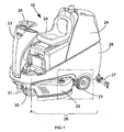
- a ride-on floor cleaning machine is shown generally at 10.
- the machine has a three-wheeler configuration with a front drive wheel 20 and two rear wheels 21 (one only visible).
- An upper portion of the machine comprises a body housing 23 which is provided at a front end region with an operator's seat 24 and a steering wheel 25.
- a rear end region 28 of the body housing houses reservoirs (not visible) for cleaning liquid solution and collected dirt-laden fluid respectively.
- the machine has a lower chassis portion which includes a cleaning head arrangement 26 for cleaning a floor and a rear vacuum squeegee blade assembly 27 for collecting liquid from the floor surface.
- a side pod 29 acts as a bumper and shrouds and houses an outer edge region of a disc-shaped lateral cleaning head (shown in figure 2 ).
- a front region 31 of the pod is pivotally mounted to the machine chassis via a boss (not shown). This permits the pod to pivot about a vertical axis A.
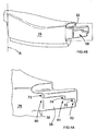
- a rear end region 30 of the pod is formed as a generally rectilinear shoulder 32, shown in figure 1B . The shoulder is located in an open C-section channel 33. Thus the rear end of the pod can slide in the channel as the pod pivots about axis A.
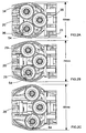
- the pod arrangement is mirrored on the other side of the machine. This is shown more clearly in figures 2A to 2D .
- each of the views 2A, 2B and 2C there are three 300mm diameter cleaning heads 34, 35 and 36 each located at the apex of a notional isosceles triangle.
- the cleaning heads are conventional in design and comprise an engineering plastics material with an annular covering of bristles (not visible).
- a central cleaning head 35 is offset rearwardly in the machine, with the two outer heads 34,36 forward and laterally spaced in relation to the rear head 35.
- the cleaning path swept by the machine corresponded to the lateral span of the two outer heads.
- Three configurations are shown, corresponding to swept paths of 650mm, 750mm and 850mm.
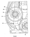
- Figure 2D is an enlarged portion from figure 2A . This shows a cleaning head mounting chuck 38. The arrangement and mounting of cleaning heads is shown more clearly in figure 3 .
- FIG. 3 is a view from above of a cleaning head mounting assembly.
- a central steel plate 41 carries a first electric motor 42 and associated drive gear hub 43.
- the drive gear is connected to a cleaning head chuck 38 which is clamped against a lower central portion (not visible) of the central cleaning head 35.
- the plate 41 is provided at each side with mounting brackets 44, 45.
- the brackets have upper ear portions (visible) and corresponding lower ear portions, with vertical axle pins therebetween.
- the bracket is thus pivotally connected to outer plates 46, 47. These plates serve as respective swinging arms, biased outwardly by respective coil springs 49.
- the outer plates each carry an electric drive motor 51, 52 for the associated outer cleaning heads 34, 36. As the outer plates splay a cleaning path of swept by the heads will be increased.
- Each of the swinging plates is provided at a distal corner region thereof with a roller wheel (54 in figure 2D ), having a vertical axis of rotation.
- This wheel contacts an inner camming surface 55 of the pod 29.
- the wheel permits resistance free splaying and retraction of the outer cleaning heads.
- the movement of the pods is governed by a mechanism shown in figures 4 to 6 .
- one of the pods 29 is shown isolated from the rest of the machine.
- the pod is moulded from engineering plastics material.
- the front pivot is shown as A.
- the rear shoulder 32 of the pod has a rear wall surface 58.
- the surface 58 is formed with three raised step features 60, 61 and 62. These step features define three outward facing facets 73, 74 and 75.
- FIG 5 the side pod 29 is shown end-on in the C-section runner channel 33.
- a rocker arm 64 has a centre pivot 65 by which the lever is attached to the channel 33.
- One inner end region 66 of the rocker arm is provided with a stop bar 67 which is a cantilever rod.
- Another outer end region 68 of the rocker arm is provided with and adjustment lever 69. The orientation of the adjustment lever and stop bar are best seen in figure 6 .
- the adjustment lever sits in one of three location slots 70 formed in the outer edge region of the runner channel 33.
- the lever permits manipulation of the rocker arm so that the stop bar can be pivoted up or down so that it abuts a desired facet 73, 74 or 75.
- each of these abutments corresponds to a different lateral displacement of the pod, and thereby also the outer cleaning heads 34,36.
- the facets provide constraint against outward splaying of the cleaning heads, but allow inner motion. This is important if an obstruction is encountered, as damage is thereby avoided.
- the passage of a machine with splayed cleaning heads in a direction of travel T through a doorway 76 is shown in figure 7 . While passing through the door way the pods are forced inwards (arrows B). Once through the doorway, the pods can move back outwards (arrows C).
Landscapes
- Nozzles For Electric Vacuum Cleaners (AREA)
- Vehicle Cleaning, Maintenance, Repair, Refitting, And Outriggers (AREA)
Claims (17)
- Fussbodenreinigungsmaschine (10) mit drei beabstandet angeordneten, dem Boden zugewandten, drehend antreibbaren Reinigungsköpfen (34, 35, 36), die jeweils eine Antriebsrotationsachse aufweisen, die im wesentlichen senkrecht zur Fussbodenebene steht, und wobei zwei seitliche Reinigungsköpfe (34, 36) jeweils auf einer Seite eines zentralen Reinigungskopfes (35) angeordnet sind, wobei die Maschine mit Radmitteln (20, 21) ausgestattet ist, die eine Translationsbewegung der Maschine entlang eines Reinigungsweges über die Fussbodenoberfläche erlauben, wobei die Maschine mit beweglichen Montiermitteln ausgestattet ist, die für eine selektive Anpassung der relativen räumlichen Anordnung der Reinigungsköpfe konfiguriert sind, sodass der Reinigungsweg, der von den Köpfen gewischt wird, angepasst werden kann, durch eine erste Anordnung, in der der Reinigungsweg, der gewischt wird, eine erste Breite aufweist, und eine Anordnung, in der der Reinigungsweg, der gewischt wird, eine zweite Breite aufweist, die der angepassten relativen räumlichen Anordnung der Reinigungsköpfe entspricht, wobei die beweglichen Montiermittel Breitenauswahlmittel (64, 65, 66, 67, 69, 70) umfassen, die angepasst sind, um eine Mehrzahl von wählbaren diskreten Reinigungswegsbreiten bereitzustellen, die jeweils einer angepassten relativen räumlichen Anordnung der Reinigungsköpfe entsprechen, dadurch gekennzeichnet, dass das Breitenauswahlmittel Gehäusebereiche (29) umfasst, die jeweils einen seitlichen Reinigungskopf ummanteln und die mit diesem während der nach außen gerichteten Bewegung, um den Reinigungsweg zu verbreitern, mitlaufen, wobei die Gehäusebereiche in ihrem nach außen gerichteten Lauf auf eine Mehrzahl diskreter Breiteneinstellungen eingeschränkt sind und wobei die Gehäusebereiche den nach außen gerichtete Lauf der seitlichen Reinigungsköpfe in einem Maße beschränken und einschränken, der durch die Gehäusebereichsbreiteneinstellung vorgegeben wird.
- Die Maschine nach Anspruch 1, wobei jeder seitliche Reinigungskopf von einem Schwenkarm (46, 47) gehalten wird, der zur Verbreiterung des Reinigungswegs ausgestellt werden kann, und jeder diesem zugeordnete Gehäusebereich an einem Ende (31) davon schwenkbar befestigt (A) ist.
- Die Maschine nach Anspruch 2, wobei jeder Schwenkarm mit einem Rad oder einer Rolle (54) ausgestattet ist, die an einer Innenfläche (55) des zugeordneten verschwenkbaren Gehäusebereichs anliegt, so dass ein Nachaußenstellen des Schwenkarms durch das auf die Innenoberfläche des Gehäusebereiches wirkende Rad oder Rolle eingeschränkt wird.
- Die Maschine nach einem der vorstehenden Ansprüche, wobei jeder Gehäusebereich (29) als Schutzpuffer ausgestaltet oder konfiguriert wird, der außerhalb des Rotationsweges der seitlichen Reinigungsköpfe angeordnet ist, um die seitlichen Köpfe gegen Schlag von äußeren Hindernissen während des Einsatzes zu schützen.
- Reinigungsmaschine nach einem der vorstehenden Ansprüche, wobei das Breitenauswahlmittel auf eine Begrenzung einer nach außen gerichteten seitlichen Bewegung der seitlichen Reinigungsköpfe hinwirkt, aber nicht eine nach innen gerichtete seitliche Bewegung der seitlichen Reinigungsköpfe verhindert.
- Die Reinigungsmaschine nach Anspruch 5, wobei das Breitenauswahlmittel eine Anordnung umfasst, bei der ein seitliches Versetzen jedes seitlichen Reinigungskopfes mit dem Eingriff einer Rastung (69, 67) an einem von mehreren beabstandet angeordneten Verschiebungsbegrenzungselementen (70, 73, 74, 75) verbunden ist.
- Die Reinigungsmaschine nach Anspruch 6, wobei die Verschiebungsbegrenzungselemente seitlich und vertikal beabstandet angeordnete, nach außen gerichtete Facetten (73, 74, 75) aufweisen, die auf einem Laufelement (29) ausgebildet sind, das sich mit einem zugeordneten seitlichen Reinigungskopf seitlich verschiebt.
- Die Reinigungsmaschine nach Anspruch 7, wobei jede Facette eine Seitenfläche eines Stufenelements aus einer Mehrzahl von Stufenelementen (73, 74, 75) umfasst, die auf einer Oberfläche (58) des Laufelements ausgebildet sind.
- Die Reinigungsmaschine nach Anspruch 7 oder Anspruch 8, wobei die Rastung eine Stange (67) umfasst, die parallel zu und gegen jede Facette angeordnet sein kann, um einen Anschlag bereitzustellen.
- Die Reinigungsmaschine nach einem der Ansprüche 7 bis 9, wobei das Laufelement der Gehäusebereich ist.
- Die Reinigungsmaschine nach Anspruch 1, wobei ein Außenbereich eines jeden seitlichen Reinigungskopfes mit einem Schutzpuffer (29) ausgestattet ist, der mit dem seitlichen Kopf während dessen seitlicher Verschiebung mitläuft.
- Die Reinigungsmaschine nach Anspruch 11, wobei der Puffer (29) an der Maschine an einem vorderen Schwenkort (A) angeordnet ist und diesem nachläuft, wobei der Puffer dadurch seitlich um die Schwenkachse schwenkt, wenn der Reinigungskopf seitlich verschoben wird.
- Die Reinigungsmaschine nach Anspruch 12, wobei der seitliche Reinigungskopf auf der Maschine über eine verschwenkbare Strebe (46, 47) montiert ist, und wobei der Drehzapfen (44, 45) der Strebe sich hinter dem vorderen Drehzapfenort befindet.
- Die Reinigungsmaschine nach Anspruch 13, wobei die Strebe in einem äußeren Bereich eine Rolle (54) trägt, die an einer Innenoberfläche des Puffers anliegt.
- Die Reinigungsmaschine nach einem der Ansprüche 11 bis 14, wobei der Puffer der Gehäusebereich ist.
- Die Reinigungsmaschine nach einem der Ansprüche 11 bis 15, wobei der nachlaufende Endbereich (32) des Puffers in einem sich im C-Bereich seitlich erstreckenden Kanal (33) verschiebbar zurückgehalten wird.
- Die Maschine nach einem der vorstehenden Ansprüche, wobei jeder Reinigungskopf (34, 35, 36) mit einem zugeordneten elektrischen Antriebsmotor (43, 51, 52) ausgestattet ist und jeder Motor (51, 52), der einem seitlichen Kopf zugeordnet ist, von einem entsprechenden Schwenkarm (46, 47) gehalten wird und mit diesem mitläuft.
Applications Claiming Priority (3)
| Application Number | Priority Date | Filing Date | Title |
|---|---|---|---|
| GB0712695A GB0712695D0 (en) | 2007-06-29 | 2007-06-29 | Floor cleaning machine |
| GB0806668A GB0806668D0 (en) | 2008-04-11 | 2008-04-11 | Floor cleaning machine |
| PCT/GB2008/002234 WO2009004320A1 (en) | 2007-06-29 | 2008-06-27 | Floor cleaning machine |
Publications (2)
| Publication Number | Publication Date |
|---|---|
| EP2170147A1 EP2170147A1 (de) | 2010-04-07 |
| EP2170147B1 true EP2170147B1 (de) | 2014-01-15 |
Family
ID=39791180
Family Applications (1)
| Application Number | Title | Priority Date | Filing Date |
|---|---|---|---|
| EP08775789.4A Not-in-force EP2170147B1 (de) | 2007-06-29 | 2008-06-27 | Fussbodenreinigungsmaschine |
Country Status (6)
| Country | Link |
|---|---|
| US (1) | US8918941B2 (de) |
| EP (1) | EP2170147B1 (de) |
| CN (1) | CN101720199B (de) |
| CA (1) | CA2691841C (de) |
| WO (1) | WO2009004320A1 (de) |
| ZA (1) | ZA201000039B (de) |
Families Citing this family (11)
| Publication number | Priority date | Publication date | Assignee | Title |
|---|---|---|---|---|
| EP2170147B1 (de) | 2007-06-29 | 2014-01-15 | Numatic International Limited | Fussbodenreinigungsmaschine |
| GB0912496D0 (en) | 2009-07-17 | 2009-08-26 | Numatic Int Ltd | Floor cleaning machine |
| CN102578975B (zh) * | 2011-01-05 | 2014-12-17 | 科沃斯机器人有限公司 | 行走装置及带有该行走装置的擦玻璃机器人 |
| GB201102410D0 (en) | 2011-02-10 | 2011-03-30 | Numatic Int Ltd | Floor cleaning machine |
| US8997905B2 (en) * | 2011-06-29 | 2015-04-07 | Dane Technologies, Inc. | Electric utility vehicle |
| EP2739196A1 (de) * | 2011-08-02 | 2014-06-11 | Alfred Kärcher GmbH & Co. KG | Fahrbare bodenreinigungsmaschine und verfahren zum betreiben einer bodenreinigungsmaschine |
| CN102525354A (zh) * | 2012-02-21 | 2012-07-04 | 宁波波朗电器有限公司 | 自动擦地机的后轮驱动结构 |
| US10219670B2 (en) | 2014-09-05 | 2019-03-05 | Tennant Company | Systems and methods for supplying treatment liquids having nanobubbles |
| US10130231B2 (en) | 2015-07-31 | 2018-11-20 | Diversey, Inc. | Floor cleaning apparatus and method of cleaning a floor |
| JP6058097B1 (ja) * | 2015-09-16 | 2017-01-11 | 株式会社エーエス | 床磨機 |
| CN106733838B (zh) * | 2016-12-21 | 2023-07-21 | 上海仁庭科技股份有限公司 | 一种便携式表面清洗装置 |
Family Cites Families (14)
| Publication number | Priority date | Publication date | Assignee | Title |
|---|---|---|---|---|
| GB712695A (en) | 1951-05-05 | 1954-07-28 | Bitulac Ltd | An improved lagging for the protection and waterproofing of thermal insulation and for the protection against corrosion of metal work, such as pipes |
| GB806668A (en) | 1956-08-03 | 1958-12-31 | Fairweather Harold G C | Chromed pyrazolone monoazo dyes |
| US3277511A (en) * | 1964-04-15 | 1966-10-11 | Nat Super Service Company | Adjustable width floor treating machine |
| US3345671A (en) * | 1966-01-11 | 1967-10-10 | Ross D Wilson | Floor scrubbing and polishing machine |
| GB2116613B (en) * | 1982-02-27 | 1985-07-24 | Schmidt Mfg & Equip | Road sweeping machine |
| FR2657769B1 (fr) | 1990-02-07 | 1994-07-29 | Miroir 2000 Sarl | Machine automotrice de traitement de surface au moyen d'agents liquides et de brosses rotatives. |
| DE4200630A1 (de) | 1991-02-01 | 1992-08-06 | Kurt Zachhuber | Bodenreinigungsmaschine |
| DE59200738D1 (de) * | 1991-02-01 | 1994-12-08 | Kurt Zachhuber | Bodenbearbeitungsmaschine. |
| US5265300A (en) | 1992-01-13 | 1993-11-30 | Aar Corp. | Floor scrubber |
| JPH06154143A (ja) | 1992-08-07 | 1994-06-03 | Johnson Kk | 床洗浄用機械 |
| FR2776684B1 (fr) * | 1998-03-26 | 2000-06-23 | Int Stifung Fur Tech Know How | Dispositif de balayage pour vehicule de voirie |
| GB0806668D0 (en) | 2008-04-11 | 2008-05-14 | Numatic Int Ltd | Floor cleaning machine |
| GB0712695D0 (en) | 2007-06-29 | 2007-08-08 | Numatic Int Ltd | Floor cleaning machine |
| EP2170147B1 (de) | 2007-06-29 | 2014-01-15 | Numatic International Limited | Fussbodenreinigungsmaschine |
-
2008
- 2008-06-27 EP EP08775789.4A patent/EP2170147B1/de not_active Not-in-force
- 2008-06-27 US US12/666,911 patent/US8918941B2/en active Active
- 2008-06-27 WO PCT/GB2008/002234 patent/WO2009004320A1/en not_active Ceased
- 2008-06-27 CN CN2008800227855A patent/CN101720199B/zh not_active Expired - Fee Related
- 2008-06-27 CA CA2691841A patent/CA2691841C/en active Active
-
2010
- 2010-01-04 ZA ZA2010/00039A patent/ZA201000039B/en unknown
Also Published As
| Publication number | Publication date |
|---|---|
| CN101720199B (zh) | 2012-12-26 |
| CN101720199A (zh) | 2010-06-02 |
| US20100180390A1 (en) | 2010-07-22 |
| WO2009004320A1 (en) | 2009-01-08 |
| CA2691841C (en) | 2015-12-29 |
| EP2170147A1 (de) | 2010-04-07 |
| ZA201000039B (en) | 2011-03-30 |
| CA2691841A1 (en) | 2009-01-08 |
| US8918941B2 (en) | 2014-12-30 |
Similar Documents
| Publication | Publication Date | Title |
|---|---|---|
| CA2691841C (en) | Floor cleaning machine | |
| EP3123915B1 (de) | Bodenreinigungsvorrichtung und verfahren zur reinigung eines bodens | |
| EP2814369B1 (de) | Oberflächenwartungsfahrzeug mit kompakter seitenbürstenanordnung | |
| US6842940B2 (en) | Floor scrubber | |
| AU762669B2 (en) | Vacuum cleaner | |
| US5265300A (en) | Floor scrubber | |
| EP0569430B1 (de) | Bodenbearbeitungsmaschine | |
| US11638511B2 (en) | Floor cleaning apparatus with offset cleaning unit | |
| DE112014000174T5 (de) | Rollenbürste für Oberflächenreinigungsroboter | |
| US4483041A (en) | Support for a squeegee assembly | |
| CN216194352U (zh) | 一种贴地清扫装置 | |
| NZ233128A (en) | Floor cleaning machine: brush pressure adjusted by altering spring tension with linear actuator | |
| US6618888B2 (en) | Dual downforce mechanism for a cleaning head of a surface conditioning vehicle | |
| JP2024523706A (ja) | 湿式クリーニング装置を搭載した自律型クリーニングロボット | |
| EP2499303A1 (de) | Mechanismus zur montage von seitenbürsten | |
| EP0621004A1 (de) | Fussbodenreinigungsmaschine | |
| EP3200667B1 (de) | Bodenreinigungsvorrichtung mit versetzter reinigungseinheit | |
| WO2023079252A1 (en) | Floor treatment machine | |
| CN221555449U (zh) | 一种越障结构及扫地机器人 |
Legal Events
| Date | Code | Title | Description |
|---|---|---|---|
| PUAI | Public reference made under article 153(3) epc to a published international application that has entered the european phase |
Free format text: ORIGINAL CODE: 0009012 |
|
| 17P | Request for examination filed |
Effective date: 20100119 |
|
| AK | Designated contracting states |
Kind code of ref document: A1 Designated state(s): AT BE BG CH CY CZ DE DK EE ES FI FR GB GR HR HU IE IS IT LI LT LU LV MC MT NL NO PL PT RO SE SI SK TR |
|
| AX | Request for extension of the european patent |
Extension state: AL BA MK RS |
|
| DAX | Request for extension of the european patent (deleted) | ||
| GRAP | Despatch of communication of intention to grant a patent |
Free format text: ORIGINAL CODE: EPIDOSNIGR1 |
|
| INTG | Intention to grant announced |
Effective date: 20130802 |
|
| GRAS | Grant fee paid |
Free format text: ORIGINAL CODE: EPIDOSNIGR3 |
|
| GRAA | (expected) grant |
Free format text: ORIGINAL CODE: 0009210 |
|
| AK | Designated contracting states |
Kind code of ref document: B1 Designated state(s): AT BE BG CH CY CZ DE DK EE ES FI FR GB GR HR HU IE IS IT LI LT LU LV MC MT NL NO PL PT RO SE SI SK TR |
|
| REG | Reference to a national code |
Ref country code: GB Ref legal event code: FG4D Ref country code: CH Ref legal event code: EP |
|
| REG | Reference to a national code |
Ref country code: AT Ref legal event code: REF Ref document number: 649405 Country of ref document: AT Kind code of ref document: T Effective date: 20140215 |
|
| REG | Reference to a national code |
Ref country code: NL Ref legal event code: T3 |
|
| REG | Reference to a national code |
Ref country code: IE Ref legal event code: FG4D |
|
| REG | Reference to a national code |
Ref country code: DE Ref legal event code: R096 Ref document number: 602008029956 Country of ref document: DE Effective date: 20140227 |
|
| REG | Reference to a national code |
Ref country code: AT Ref legal event code: MK05 Ref document number: 649405 Country of ref document: AT Kind code of ref document: T Effective date: 20140115 |
|
| REG | Reference to a national code |
Ref country code: LT Ref legal event code: MG4D |
|
| PG25 | Lapsed in a contracting state [announced via postgrant information from national office to epo] |
Ref country code: IS Free format text: LAPSE BECAUSE OF FAILURE TO SUBMIT A TRANSLATION OF THE DESCRIPTION OR TO PAY THE FEE WITHIN THE PRESCRIBED TIME-LIMIT Effective date: 20140515 Ref country code: LT Free format text: LAPSE BECAUSE OF FAILURE TO SUBMIT A TRANSLATION OF THE DESCRIPTION OR TO PAY THE FEE WITHIN THE PRESCRIBED TIME-LIMIT Effective date: 20140115 Ref country code: NO Free format text: LAPSE BECAUSE OF FAILURE TO SUBMIT A TRANSLATION OF THE DESCRIPTION OR TO PAY THE FEE WITHIN THE PRESCRIBED TIME-LIMIT Effective date: 20140415 |
|
| PG25 | Lapsed in a contracting state [announced via postgrant information from national office to epo] |
Ref country code: SE Free format text: LAPSE BECAUSE OF FAILURE TO SUBMIT A TRANSLATION OF THE DESCRIPTION OR TO PAY THE FEE WITHIN THE PRESCRIBED TIME-LIMIT Effective date: 20140115 Ref country code: FI Free format text: LAPSE BECAUSE OF FAILURE TO SUBMIT A TRANSLATION OF THE DESCRIPTION OR TO PAY THE FEE WITHIN THE PRESCRIBED TIME-LIMIT Effective date: 20140115 Ref country code: PT Free format text: LAPSE BECAUSE OF FAILURE TO SUBMIT A TRANSLATION OF THE DESCRIPTION OR TO PAY THE FEE WITHIN THE PRESCRIBED TIME-LIMIT Effective date: 20140515 Ref country code: AT Free format text: LAPSE BECAUSE OF FAILURE TO SUBMIT A TRANSLATION OF THE DESCRIPTION OR TO PAY THE FEE WITHIN THE PRESCRIBED TIME-LIMIT Effective date: 20140115 Ref country code: ES Free format text: LAPSE BECAUSE OF FAILURE TO SUBMIT A TRANSLATION OF THE DESCRIPTION OR TO PAY THE FEE WITHIN THE PRESCRIBED TIME-LIMIT Effective date: 20140115 Ref country code: CY Free format text: LAPSE BECAUSE OF FAILURE TO SUBMIT A TRANSLATION OF THE DESCRIPTION OR TO PAY THE FEE WITHIN THE PRESCRIBED TIME-LIMIT Effective date: 20140115 |
|
| PG25 | Lapsed in a contracting state [announced via postgrant information from national office to epo] |
Ref country code: BE Free format text: LAPSE BECAUSE OF FAILURE TO SUBMIT A TRANSLATION OF THE DESCRIPTION OR TO PAY THE FEE WITHIN THE PRESCRIBED TIME-LIMIT Effective date: 20140115 Ref country code: LV Free format text: LAPSE BECAUSE OF FAILURE TO SUBMIT A TRANSLATION OF THE DESCRIPTION OR TO PAY THE FEE WITHIN THE PRESCRIBED TIME-LIMIT Effective date: 20140115 Ref country code: HR Free format text: LAPSE BECAUSE OF FAILURE TO SUBMIT A TRANSLATION OF THE DESCRIPTION OR TO PAY THE FEE WITHIN THE PRESCRIBED TIME-LIMIT Effective date: 20140115 |
|
| REG | Reference to a national code |
Ref country code: DE Ref legal event code: R097 Ref document number: 602008029956 Country of ref document: DE |
|
| PG25 | Lapsed in a contracting state [announced via postgrant information from national office to epo] |
Ref country code: RO Free format text: LAPSE BECAUSE OF FAILURE TO SUBMIT A TRANSLATION OF THE DESCRIPTION OR TO PAY THE FEE WITHIN THE PRESCRIBED TIME-LIMIT Effective date: 20140115 Ref country code: CZ Free format text: LAPSE BECAUSE OF FAILURE TO SUBMIT A TRANSLATION OF THE DESCRIPTION OR TO PAY THE FEE WITHIN THE PRESCRIBED TIME-LIMIT Effective date: 20140115 Ref country code: EE Free format text: LAPSE BECAUSE OF FAILURE TO SUBMIT A TRANSLATION OF THE DESCRIPTION OR TO PAY THE FEE WITHIN THE PRESCRIBED TIME-LIMIT Effective date: 20140115 Ref country code: DK Free format text: LAPSE BECAUSE OF FAILURE TO SUBMIT A TRANSLATION OF THE DESCRIPTION OR TO PAY THE FEE WITHIN THE PRESCRIBED TIME-LIMIT Effective date: 20140115 |
|
| PLBE | No opposition filed within time limit |
Free format text: ORIGINAL CODE: 0009261 |
|
| STAA | Information on the status of an ep patent application or granted ep patent |
Free format text: STATUS: NO OPPOSITION FILED WITHIN TIME LIMIT |
|
| PG25 | Lapsed in a contracting state [announced via postgrant information from national office to epo] |
Ref country code: SK Free format text: LAPSE BECAUSE OF FAILURE TO SUBMIT A TRANSLATION OF THE DESCRIPTION OR TO PAY THE FEE WITHIN THE PRESCRIBED TIME-LIMIT Effective date: 20140115 Ref country code: PL Free format text: LAPSE BECAUSE OF FAILURE TO SUBMIT A TRANSLATION OF THE DESCRIPTION OR TO PAY THE FEE WITHIN THE PRESCRIBED TIME-LIMIT Effective date: 20140115 |
|
| 26N | No opposition filed |
Effective date: 20141016 |
|
| PG25 | Lapsed in a contracting state [announced via postgrant information from national office to epo] |
Ref country code: LU Free format text: LAPSE BECAUSE OF FAILURE TO SUBMIT A TRANSLATION OF THE DESCRIPTION OR TO PAY THE FEE WITHIN THE PRESCRIBED TIME-LIMIT Effective date: 20140627 Ref country code: MC Free format text: LAPSE BECAUSE OF FAILURE TO SUBMIT A TRANSLATION OF THE DESCRIPTION OR TO PAY THE FEE WITHIN THE PRESCRIBED TIME-LIMIT Effective date: 20140115 |
|
| REG | Reference to a national code |
Ref country code: CH Ref legal event code: PL |
|
| REG | Reference to a national code |
Ref country code: DE Ref legal event code: R097 Ref document number: 602008029956 Country of ref document: DE Effective date: 20141016 |
|
| REG | Reference to a national code |
Ref country code: IE Ref legal event code: MM4A |
|
| PG25 | Lapsed in a contracting state [announced via postgrant information from national office to epo] |
Ref country code: IE Free format text: LAPSE BECAUSE OF NON-PAYMENT OF DUE FEES Effective date: 20140627 Ref country code: CH Free format text: LAPSE BECAUSE OF NON-PAYMENT OF DUE FEES Effective date: 20140630 Ref country code: LI Free format text: LAPSE BECAUSE OF NON-PAYMENT OF DUE FEES Effective date: 20140630 |
|
| PG25 | Lapsed in a contracting state [announced via postgrant information from national office to epo] |
Ref country code: SI Free format text: LAPSE BECAUSE OF FAILURE TO SUBMIT A TRANSLATION OF THE DESCRIPTION OR TO PAY THE FEE WITHIN THE PRESCRIBED TIME-LIMIT Effective date: 20140115 |
|
| PG25 | Lapsed in a contracting state [announced via postgrant information from national office to epo] |
Ref country code: MT Free format text: LAPSE BECAUSE OF FAILURE TO SUBMIT A TRANSLATION OF THE DESCRIPTION OR TO PAY THE FEE WITHIN THE PRESCRIBED TIME-LIMIT Effective date: 20140115 |
|
| PG25 | Lapsed in a contracting state [announced via postgrant information from national office to epo] |
Ref country code: BG Free format text: LAPSE BECAUSE OF FAILURE TO SUBMIT A TRANSLATION OF THE DESCRIPTION OR TO PAY THE FEE WITHIN THE PRESCRIBED TIME-LIMIT Effective date: 20140115 |
|
| REG | Reference to a national code |
Ref country code: FR Ref legal event code: PLFP Year of fee payment: 9 |
|
| PG25 | Lapsed in a contracting state [announced via postgrant information from national office to epo] |
Ref country code: GR Free format text: LAPSE BECAUSE OF FAILURE TO SUBMIT A TRANSLATION OF THE DESCRIPTION OR TO PAY THE FEE WITHIN THE PRESCRIBED TIME-LIMIT Effective date: 20140416 Ref country code: IT Free format text: LAPSE BECAUSE OF FAILURE TO SUBMIT A TRANSLATION OF THE DESCRIPTION OR TO PAY THE FEE WITHIN THE PRESCRIBED TIME-LIMIT Effective date: 20140115 |
|
| PG25 | Lapsed in a contracting state [announced via postgrant information from national office to epo] |
Ref country code: TR Free format text: LAPSE BECAUSE OF FAILURE TO SUBMIT A TRANSLATION OF THE DESCRIPTION OR TO PAY THE FEE WITHIN THE PRESCRIBED TIME-LIMIT Effective date: 20140115 Ref country code: HU Free format text: LAPSE BECAUSE OF FAILURE TO SUBMIT A TRANSLATION OF THE DESCRIPTION OR TO PAY THE FEE WITHIN THE PRESCRIBED TIME-LIMIT; INVALID AB INITIO Effective date: 20080627 |
|
| REG | Reference to a national code |
Ref country code: FR Ref legal event code: PLFP Year of fee payment: 10 |
|
| REG | Reference to a national code |
Ref country code: FR Ref legal event code: PLFP Year of fee payment: 11 |
|
| P01 | Opt-out of the competence of the unified patent court (upc) registered |
Effective date: 20230519 |
|
| PGFP | Annual fee paid to national office [announced via postgrant information from national office to epo] |
Ref country code: NL Payment date: 20230623 Year of fee payment: 16 Ref country code: FR Payment date: 20230622 Year of fee payment: 16 |
|
| PGFP | Annual fee paid to national office [announced via postgrant information from national office to epo] |
Ref country code: GB Payment date: 20230630 Year of fee payment: 16 |
|
| PGFP | Annual fee paid to national office [announced via postgrant information from national office to epo] |
Ref country code: DE Payment date: 20230719 Year of fee payment: 16 |
|
| REG | Reference to a national code |
Ref country code: DE Ref legal event code: R119 Ref document number: 602008029956 Country of ref document: DE |
|
| REG | Reference to a national code |
Ref country code: NL Ref legal event code: MM Effective date: 20240701 |
|
| GBPC | Gb: european patent ceased through non-payment of renewal fee |
Effective date: 20240627 |
|
| PG25 | Lapsed in a contracting state [announced via postgrant information from national office to epo] |
Ref country code: NL Free format text: LAPSE BECAUSE OF NON-PAYMENT OF DUE FEES Effective date: 20240701 |
|
| PG25 | Lapsed in a contracting state [announced via postgrant information from national office to epo] |
Ref country code: NL Free format text: LAPSE BECAUSE OF NON-PAYMENT OF DUE FEES Effective date: 20240701 |
|
| PG25 | Lapsed in a contracting state [announced via postgrant information from national office to epo] |
Ref country code: DE Free format text: LAPSE BECAUSE OF NON-PAYMENT OF DUE FEES Effective date: 20250101 |
|
| PG25 | Lapsed in a contracting state [announced via postgrant information from national office to epo] |
Ref country code: FR Free format text: LAPSE BECAUSE OF NON-PAYMENT OF DUE FEES Effective date: 20240630 |
|
| PG25 | Lapsed in a contracting state [announced via postgrant information from national office to epo] |
Ref country code: GB Free format text: LAPSE BECAUSE OF NON-PAYMENT OF DUE FEES Effective date: 20240627 |