US10130231B2 - Floor cleaning apparatus and method of cleaning a floor - Google Patents
Floor cleaning apparatus and method of cleaning a floor Download PDFInfo
- Publication number
- US10130231B2 US10130231B2 US15/221,753 US201615221753A US10130231B2 US 10130231 B2 US10130231 B2 US 10130231B2 US 201615221753 A US201615221753 A US 201615221753A US 10130231 B2 US10130231 B2 US 10130231B2
- Authority
- US
- United States
- Prior art keywords
- floor
- brushes
- cleaning apparatus
- turntable
- drive wheel
- Prior art date
- Legal status (The legal status is an assumption and is not a legal conclusion. Google has not performed a legal analysis and makes no representation as to the accuracy of the status listed.)
- Active, expires
Links
Images


Classifications
-
- A—HUMAN NECESSITIES
- A47—FURNITURE; DOMESTIC ARTICLES OR APPLIANCES; COFFEE MILLS; SPICE MILLS; SUCTION CLEANERS IN GENERAL
- A47L—DOMESTIC WASHING OR CLEANING; SUCTION CLEANERS IN GENERAL
- A47L11/00—Machines for cleaning floors, carpets, furniture, walls, or wall coverings
- A47L11/29—Floor-scrubbing machines characterised by means for taking-up dirty liquid
- A47L11/30—Floor-scrubbing machines characterised by means for taking-up dirty liquid by suction
- A47L11/302—Floor-scrubbing machines characterised by means for taking-up dirty liquid by suction having rotary tools
- A47L11/305—Floor-scrubbing machines characterised by means for taking-up dirty liquid by suction having rotary tools the tools being disc brushes
-
- A—HUMAN NECESSITIES
- A47—FURNITURE; DOMESTIC ARTICLES OR APPLIANCES; COFFEE MILLS; SPICE MILLS; SUCTION CLEANERS IN GENERAL
- A47L—DOMESTIC WASHING OR CLEANING; SUCTION CLEANERS IN GENERAL
- A47L11/00—Machines for cleaning floors, carpets, furniture, walls, or wall coverings
- A47L11/24—Floor-sweeping machines, motor-driven
-
- A—HUMAN NECESSITIES
- A47—FURNITURE; DOMESTIC ARTICLES OR APPLIANCES; COFFEE MILLS; SPICE MILLS; SUCTION CLEANERS IN GENERAL
- A47L—DOMESTIC WASHING OR CLEANING; SUCTION CLEANERS IN GENERAL
- A47L11/00—Machines for cleaning floors, carpets, furniture, walls, or wall coverings
- A47L11/28—Floor-scrubbing machines, motor-driven
- A47L11/282—Floor-scrubbing machines, motor-driven having rotary tools
- A47L11/283—Floor-scrubbing machines, motor-driven having rotary tools the tools being disc brushes
-
- A—HUMAN NECESSITIES
- A47—FURNITURE; DOMESTIC ARTICLES OR APPLIANCES; COFFEE MILLS; SPICE MILLS; SUCTION CLEANERS IN GENERAL
- A47L—DOMESTIC WASHING OR CLEANING; SUCTION CLEANERS IN GENERAL
- A47L11/00—Machines for cleaning floors, carpets, furniture, walls, or wall coverings
- A47L11/29—Floor-scrubbing machines characterised by means for taking-up dirty liquid
- A47L11/292—Floor-scrubbing machines characterised by means for taking-up dirty liquid having rotary tools
- A47L11/293—Floor-scrubbing machines characterised by means for taking-up dirty liquid having rotary tools the tools being disc brushes
-
- A—HUMAN NECESSITIES
- A47—FURNITURE; DOMESTIC ARTICLES OR APPLIANCES; COFFEE MILLS; SPICE MILLS; SUCTION CLEANERS IN GENERAL
- A47L—DOMESTIC WASHING OR CLEANING; SUCTION CLEANERS IN GENERAL
- A47L11/00—Machines for cleaning floors, carpets, furniture, walls, or wall coverings
- A47L11/29—Floor-scrubbing machines characterised by means for taking-up dirty liquid
- A47L11/30—Floor-scrubbing machines characterised by means for taking-up dirty liquid by suction
- A47L11/307—Floor-scrubbing machines characterised by means for taking-up dirty liquid by suction having reciprocating tools
-
- A—HUMAN NECESSITIES
- A47—FURNITURE; DOMESTIC ARTICLES OR APPLIANCES; COFFEE MILLS; SPICE MILLS; SUCTION CLEANERS IN GENERAL
- A47L—DOMESTIC WASHING OR CLEANING; SUCTION CLEANERS IN GENERAL
- A47L11/00—Machines for cleaning floors, carpets, furniture, walls, or wall coverings
- A47L11/40—Parts or details of machines not provided for in groups A47L11/02 - A47L11/38, or not restricted to one of these groups, e.g. handles, arrangements of switches, skirts, buffers, levers
- A47L11/4036—Parts or details of the surface treating tools
- A47L11/4038—Disk shaped surface treating tools
-
- E—FIXED CONSTRUCTIONS
- E01—CONSTRUCTION OF ROADS, RAILWAYS, OR BRIDGES
- E01H—STREET CLEANING; CLEANING OF PERMANENT WAYS; CLEANING BEACHES; DISPERSING OR PREVENTING FOG IN GENERAL CLEANING STREET OR RAILWAY FURNITURE OR TUNNEL WALLS
- E01H1/00—Removing undesirable matter from roads or like surfaces, with or without moistening of the surface
- E01H1/02—Brushing apparatus, e.g. with auxiliary instruments for mechanically loosening dirt
- E01H1/05—Brushing apparatus, e.g. with auxiliary instruments for mechanically loosening dirt with driven brushes
- E01H1/053—Brushing apparatus, e.g. with auxiliary instruments for mechanically loosening dirt with driven brushes having vertical axes
-
- A—HUMAN NECESSITIES
- A47—FURNITURE; DOMESTIC ARTICLES OR APPLIANCES; COFFEE MILLS; SPICE MILLS; SUCTION CLEANERS IN GENERAL
- A47L—DOMESTIC WASHING OR CLEANING; SUCTION CLEANERS IN GENERAL
- A47L11/00—Machines for cleaning floors, carpets, furniture, walls, or wall coverings
- A47L11/40—Parts or details of machines not provided for in groups A47L11/02 - A47L11/38, or not restricted to one of these groups, e.g. handles, arrangements of switches, skirts, buffers, levers
- A47L11/4013—Contaminants collecting devices, i.e. hoppers, tanks or the like
- A47L11/4016—Contaminants collecting devices, i.e. hoppers, tanks or the like specially adapted for collecting fluids
-
- A—HUMAN NECESSITIES
- A47—FURNITURE; DOMESTIC ARTICLES OR APPLIANCES; COFFEE MILLS; SPICE MILLS; SUCTION CLEANERS IN GENERAL
- A47L—DOMESTIC WASHING OR CLEANING; SUCTION CLEANERS IN GENERAL
- A47L11/00—Machines for cleaning floors, carpets, furniture, walls, or wall coverings
- A47L11/40—Parts or details of machines not provided for in groups A47L11/02 - A47L11/38, or not restricted to one of these groups, e.g. handles, arrangements of switches, skirts, buffers, levers
- A47L11/4036—Parts or details of the surface treating tools
- A47L11/4044—Vacuuming or pick-up tools; Squeegees
-
- A—HUMAN NECESSITIES
- A47—FURNITURE; DOMESTIC ARTICLES OR APPLIANCES; COFFEE MILLS; SPICE MILLS; SUCTION CLEANERS IN GENERAL
- A47L—DOMESTIC WASHING OR CLEANING; SUCTION CLEANERS IN GENERAL
- A47L11/00—Machines for cleaning floors, carpets, furniture, walls, or wall coverings
- A47L11/40—Parts or details of machines not provided for in groups A47L11/02 - A47L11/38, or not restricted to one of these groups, e.g. handles, arrangements of switches, skirts, buffers, levers
- A47L11/4052—Movement of the tools or the like perpendicular to the cleaning surface
- A47L11/4055—Movement of the tools or the like perpendicular to the cleaning surface for lifting the tools to a non-working position
-
- A—HUMAN NECESSITIES
- A47—FURNITURE; DOMESTIC ARTICLES OR APPLIANCES; COFFEE MILLS; SPICE MILLS; SUCTION CLEANERS IN GENERAL
- A47L—DOMESTIC WASHING OR CLEANING; SUCTION CLEANERS IN GENERAL
- A47L11/00—Machines for cleaning floors, carpets, furniture, walls, or wall coverings
- A47L11/40—Parts or details of machines not provided for in groups A47L11/02 - A47L11/38, or not restricted to one of these groups, e.g. handles, arrangements of switches, skirts, buffers, levers
- A47L11/4061—Steering means; Means for avoiding obstacles; Details related to the place where the driver is accommodated
-
- A—HUMAN NECESSITIES
- A47—FURNITURE; DOMESTIC ARTICLES OR APPLIANCES; COFFEE MILLS; SPICE MILLS; SUCTION CLEANERS IN GENERAL
- A47L—DOMESTIC WASHING OR CLEANING; SUCTION CLEANERS IN GENERAL
- A47L11/00—Machines for cleaning floors, carpets, furniture, walls, or wall coverings
- A47L11/40—Parts or details of machines not provided for in groups A47L11/02 - A47L11/38, or not restricted to one of these groups, e.g. handles, arrangements of switches, skirts, buffers, levers
- A47L11/4063—Driving means; Transmission means therefor
- A47L11/4066—Propulsion of the whole machine
-
- A—HUMAN NECESSITIES
- A47—FURNITURE; DOMESTIC ARTICLES OR APPLIANCES; COFFEE MILLS; SPICE MILLS; SUCTION CLEANERS IN GENERAL
- A47L—DOMESTIC WASHING OR CLEANING; SUCTION CLEANERS IN GENERAL
- A47L11/00—Machines for cleaning floors, carpets, furniture, walls, or wall coverings
- A47L11/40—Parts or details of machines not provided for in groups A47L11/02 - A47L11/38, or not restricted to one of these groups, e.g. handles, arrangements of switches, skirts, buffers, levers
- A47L11/4063—Driving means; Transmission means therefor
- A47L11/4069—Driving or transmission means for the cleaning tools
-
- A—HUMAN NECESSITIES
- A47—FURNITURE; DOMESTIC ARTICLES OR APPLIANCES; COFFEE MILLS; SPICE MILLS; SUCTION CLEANERS IN GENERAL
- A47L—DOMESTIC WASHING OR CLEANING; SUCTION CLEANERS IN GENERAL
- A47L11/00—Machines for cleaning floors, carpets, furniture, walls, or wall coverings
- A47L11/40—Parts or details of machines not provided for in groups A47L11/02 - A47L11/38, or not restricted to one of these groups, e.g. handles, arrangements of switches, skirts, buffers, levers
- A47L11/4072—Arrangement of castors or wheels
-
- A—HUMAN NECESSITIES
- A47—FURNITURE; DOMESTIC ARTICLES OR APPLIANCES; COFFEE MILLS; SPICE MILLS; SUCTION CLEANERS IN GENERAL
- A47L—DOMESTIC WASHING OR CLEANING; SUCTION CLEANERS IN GENERAL
- A47L11/00—Machines for cleaning floors, carpets, furniture, walls, or wall coverings
- A47L11/40—Parts or details of machines not provided for in groups A47L11/02 - A47L11/38, or not restricted to one of these groups, e.g. handles, arrangements of switches, skirts, buffers, levers
- A47L11/408—Means for supplying cleaning or surface treating agents
- A47L11/4083—Liquid supply reservoirs; Preparation of the agents, e.g. mixing devices
-
- A—HUMAN NECESSITIES
- A47—FURNITURE; DOMESTIC ARTICLES OR APPLIANCES; COFFEE MILLS; SPICE MILLS; SUCTION CLEANERS IN GENERAL
- A47L—DOMESTIC WASHING OR CLEANING; SUCTION CLEANERS IN GENERAL
- A47L11/00—Machines for cleaning floors, carpets, furniture, walls, or wall coverings
- A47L11/40—Parts or details of machines not provided for in groups A47L11/02 - A47L11/38, or not restricted to one of these groups, e.g. handles, arrangements of switches, skirts, buffers, levers
- A47L11/408—Means for supplying cleaning or surface treating agents
- A47L11/4088—Supply pumps; Spraying devices; Supply conduits
Definitions
- a floor cleaning apparatus for cleaning a floor comprises a housing, a chassis, a plurality of wheels by which the floor cleaning apparatus is adapted to move across the floor in a direction of travel, the direction of travel at least partially defining a front end, a back end, and first and second lateral sides of the floor cleaning apparatus, a motive device for moving the apparatus across the floor, a steering mechanism, a cleaning assembly for cleaning the floor, and a side sweeping system comprising a turntable having a central axis, a drive wheel, the drive wheel disposed in coaxial relationship with the turntable, a sweeper motive device for rotating the drive wheel, a plurality of brushes each having a central axis, the brushes distributed radially around the drive wheel and driven by rotation of the drive wheel, and a pivoting connector configured to enable the side sweeping system to pivot laterally away from a neutral position in response to contact with a vertical surface while at least one of the plurality of brushes maintains contact with the floor adjacent the vertical surface while the floor cleaning apparatus is in operation
- FIG. 17 is a perspective view of relevant portions of a floor cleaning apparatus with a pick-up system
- the brushes can be of any suitable material, size, shape, and bristle density and pattern.
- the brushes of brush assembly 62 and 64 are offset from each other with respect to the longitudinal centerline of the floor cleaning apparatus; i.e. a brush centerline running through the center of the two brushes is in one embodiment not perpendicular to the longitudinal center line of the apparatus, or is not transverse to the direction of travel of the apparatus during operation.
- Such an arrangement minimizes the lateral extent of the cleaning assembly 60 to control the lateral extent of the apparatus 10 , and so that the apparatus 10 can pass through relatively narrow slots, spaces or passageways.
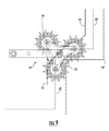
- Motive force can in turn be transmitted from drive wheel 87 to each respective brush 74 by any suitable mechanism, such as for example by a brush drive belt 77 (see FIG. 21 ).
- Side sweeping system 70 can be operated independently of cleaning assembly 60 , and independently of a front sweeping system 88 (if present). Alternatively, side sweeping system 70 can be operated while the cleaning assembly 60 is activated, and/or in combination with front sweeping system 88 . Side sweeping system 70 can be operated by the operator from a dashboard, and can be lifted out of the way either manually or mechanically, e.g by a mechanical motor-driven system.
- FIG. 2 shows a lifting device 84 that permits vertical lifting of the side sweeping system 70 as needed during non-cleaning travel or storage of the floor cleaning apparatus 10 .
- the lifting device 84 includes a four-bar linkage.
- the lifting device 84 may include a telescoping hydraulic or pneumatic rod.
- FIG. 19 shows a side sweeping system 70 that is schematically attached to chassis 40 at support arm 66 .
- the support arm 66 may be coupled to the chassis 40 in a number of different ways, including for example a four-bar linkage as shown in FIG. 2 or as part of a telescoping arrangement.
- a vertical biasing member 67 may be used as part of the coupling arrangement to help support the weight of the side sweeping system 70 .
- a vertical biasing member 70 may assist in keeping the brushes 74 suspended above the surface to be cleaned for optimal sweeping action.
- the vertical biasing member 70 may be implemented as a spring, such as a coil spring, torsion spring, or a leaf spring.
Abstract
Description
Claims (15)
Priority Applications (2)
| Application Number | Priority Date | Filing Date | Title |
|---|---|---|---|
| US15/221,753 US10130231B2 (en) | 2015-07-31 | 2016-07-28 | Floor cleaning apparatus and method of cleaning a floor |
| US16/194,493 US11071431B2 (en) | 2015-07-31 | 2018-11-19 | Floor cleaning apparatus and method of cleaning a floor |
Applications Claiming Priority (2)
| Application Number | Priority Date | Filing Date | Title |
|---|---|---|---|
| US201562199282P | 2015-07-31 | 2015-07-31 | |
| US15/221,753 US10130231B2 (en) | 2015-07-31 | 2016-07-28 | Floor cleaning apparatus and method of cleaning a floor |
Related Child Applications (1)
| Application Number | Title | Priority Date | Filing Date |
|---|---|---|---|
| US16/194,493 Division US11071431B2 (en) | 2015-07-31 | 2018-11-19 | Floor cleaning apparatus and method of cleaning a floor |
Publications (2)
| Publication Number | Publication Date |
|---|---|
| US20170027401A1 US20170027401A1 (en) | 2017-02-02 |
| US10130231B2 true US10130231B2 (en) | 2018-11-20 |
Family
ID=56557596
Family Applications (2)
| Application Number | Title | Priority Date | Filing Date |
|---|---|---|---|
| US15/221,753 Active 2037-01-02 US10130231B2 (en) | 2015-07-31 | 2016-07-28 | Floor cleaning apparatus and method of cleaning a floor |
| US16/194,493 Active 2037-10-09 US11071431B2 (en) | 2015-07-31 | 2018-11-19 | Floor cleaning apparatus and method of cleaning a floor |
Family Applications After (1)
| Application Number | Title | Priority Date | Filing Date |
|---|---|---|---|
| US16/194,493 Active 2037-10-09 US11071431B2 (en) | 2015-07-31 | 2018-11-19 | Floor cleaning apparatus and method of cleaning a floor |
Country Status (3)
| Country | Link |
|---|---|
| US (2) | US10130231B2 (en) |
| EP (1) | EP3123915B1 (en) |
| JP (1) | JP6691013B2 (en) |
Families Citing this family (14)
| Publication number | Priority date | Publication date | Assignee | Title |
|---|---|---|---|---|
| US10190286B2 (en) * | 2017-03-20 | 2019-01-29 | Deere & Company | Debris deflection apparatus for operators station cleanout |
| DE102018008269A1 (en) * | 2018-04-13 | 2019-10-17 | Hako Gmbh | street sweeper |
| CN109008821A (en) * | 2018-09-02 | 2018-12-18 | 安徽风向标清洁设备有限公司 | A kind of novel totally enclosed type sweeper |
| KR102130711B1 (en) | 2018-11-30 | 2020-07-06 | 주식회사 에이엠 특장 | Floor electric sweeper |
| KR101997911B1 (en) | 2018-11-30 | 2019-07-08 | 윤홍식 | Floor electric sweeper |
| KR102130710B1 (en) | 2018-11-30 | 2020-07-06 | 주식회사 에이엠 특장 | Floor electric sweeper |
| WO2020132482A1 (en) * | 2018-12-21 | 2020-06-25 | Tennant Company | Sweeper/scrubber system capable of handling large debris |
| CN112401772B (en) * | 2019-08-21 | 2021-08-31 | 滁州扬子清洁设备有限公司 | Dead-angle-free hand-push type self-propelled floor washing machine |
| CN112914431B (en) * | 2021-03-25 | 2022-06-21 | 云鲸智能科技(东莞)有限公司 | Cleaning assembly and cleaning robot |
| CN113273929B (en) * | 2021-05-25 | 2022-05-13 | 淮北智行信息科技有限公司 | No dead angle robot of sweeping floor |
| CN113668441A (en) * | 2021-07-24 | 2021-11-19 | 中交第四公路工程局有限公司 | Movable green construction flushing device |
| CN113576332A (en) * | 2021-08-04 | 2021-11-02 | 上海高仙自动化科技发展有限公司 | Cleaning robot |
| CN113854905A (en) * | 2021-10-15 | 2021-12-31 | 深圳乐生机器人智能科技有限公司 | Brush is swept multi-functional robot of sweeping floor of type of trading fast |
| CN114271737B (en) * | 2022-01-26 | 2022-11-29 | 深圳巴诺机器人有限公司 | Control method and device of welcome type sweeper |
Citations (10)
| Publication number | Priority date | Publication date | Assignee | Title |
|---|---|---|---|---|
| US3201819A (en) | 1961-11-17 | 1965-08-24 | Lambert Inc | Sweeper |
| US3277511A (en) * | 1964-04-15 | 1966-10-11 | Nat Super Service Company | Adjustable width floor treating machine |
| US3866541A (en) * | 1972-03-24 | 1975-02-18 | Connor James M O | Self-propelled floor cleaning apparatus with movable brush |
| US20020138939A1 (en) * | 2001-03-07 | 2002-10-03 | Minuteman International, Inc., (An Illinois Corporation) | Litter vacuum |
| US7313839B2 (en) * | 2001-05-29 | 2008-01-01 | Tennant Company | Sweeping system with front removable hopper |
| US20110107529A1 (en) * | 2009-11-09 | 2011-05-12 | Tennant Company | Side Brush Assembly Mechanism |
| WO2012171579A1 (en) | 2011-06-17 | 2012-12-20 | Alfred Kärcher Gmbh & Co. Kg | Sweeping vehicle having a brush disk adjuster |
| EP2685004A1 (en) | 2012-07-11 | 2014-01-15 | Etablissements Emily | Sweeping machine whose main brush is driven by a mechanical transmission allowing adjustment of the brush |
| US20140101874A1 (en) * | 2011-06-17 | 2014-04-17 | Alfred Kärcher Gmbh & Co. Kg | Sweeping vehicle |
| US9498099B2 (en) * | 2012-02-16 | 2016-11-22 | Tennant Company | Surface maintenance vehicle with compact side brush assembly |
Family Cites Families (4)
| Publication number | Priority date | Publication date | Assignee | Title |
|---|---|---|---|---|
| ATE342685T1 (en) | 2004-05-07 | 2006-11-15 | Johnson Diversey Inc | SOIL TREATMENT AND CLEANING SYSTEM |
| CA2841526C (en) | 2005-12-22 | 2016-12-06 | Diversey, Inc. | Squeegee assembly for a floor cleaning machine |
| EP2170147B1 (en) | 2007-06-29 | 2014-01-15 | Numatic International Limited | Floor cleaning machine |
| JP5243879B2 (en) | 2008-08-04 | 2013-07-24 | 富士重工業株式会社 | Side brush support device for cleaning robot |
-
2016
- 2016-07-28 US US15/221,753 patent/US10130231B2/en active Active
- 2016-07-29 EP EP16182034.5A patent/EP3123915B1/en active Active
- 2016-07-29 JP JP2016149400A patent/JP6691013B2/en not_active Expired - Fee Related
-
2018
- 2018-11-19 US US16/194,493 patent/US11071431B2/en active Active
Patent Citations (11)
| Publication number | Priority date | Publication date | Assignee | Title |
|---|---|---|---|---|
| US3201819A (en) | 1961-11-17 | 1965-08-24 | Lambert Inc | Sweeper |
| US3277511A (en) * | 1964-04-15 | 1966-10-11 | Nat Super Service Company | Adjustable width floor treating machine |
| US3866541A (en) * | 1972-03-24 | 1975-02-18 | Connor James M O | Self-propelled floor cleaning apparatus with movable brush |
| US20020138939A1 (en) * | 2001-03-07 | 2002-10-03 | Minuteman International, Inc., (An Illinois Corporation) | Litter vacuum |
| US7313839B2 (en) * | 2001-05-29 | 2008-01-01 | Tennant Company | Sweeping system with front removable hopper |
| US20110107529A1 (en) * | 2009-11-09 | 2011-05-12 | Tennant Company | Side Brush Assembly Mechanism |
| US8769755B2 (en) | 2009-11-09 | 2014-07-08 | Tennant Company | Side brush assembly mechanism |
| WO2012171579A1 (en) | 2011-06-17 | 2012-12-20 | Alfred Kärcher Gmbh & Co. Kg | Sweeping vehicle having a brush disk adjuster |
| US20140101874A1 (en) * | 2011-06-17 | 2014-04-17 | Alfred Kärcher Gmbh & Co. Kg | Sweeping vehicle |
| US9498099B2 (en) * | 2012-02-16 | 2016-11-22 | Tennant Company | Surface maintenance vehicle with compact side brush assembly |
| EP2685004A1 (en) | 2012-07-11 | 2014-01-15 | Etablissements Emily | Sweeping machine whose main brush is driven by a mechanical transmission allowing adjustment of the brush |
Non-Patent Citations (1)
| Title |
|---|
| Extended European Search Report from the European Patent Office. dated Jan. 19, 2017. |
Also Published As
| Publication number | Publication date |
|---|---|
| EP3123915B1 (en) | 2020-10-28 |
| EP3123915A3 (en) | 2017-02-22 |
| US20190082921A1 (en) | 2019-03-21 |
| JP2017029728A (en) | 2017-02-09 |
| US20170027401A1 (en) | 2017-02-02 |
| JP6691013B2 (en) | 2020-04-28 |
| US11071431B2 (en) | 2021-07-27 |
| EP3123915A2 (en) | 2017-02-01 |
Similar Documents
| Publication | Publication Date | Title |
|---|---|---|
| US11071431B2 (en) | Floor cleaning apparatus and method of cleaning a floor | |
| AU2006244470B2 (en) | Floor sweeping and scrubbing machine | |
| US20120137464A1 (en) | Mopping Machine | |
| US9498099B2 (en) | Surface maintenance vehicle with compact side brush assembly | |
| CA2515377A1 (en) | Floor scrubber | |
| JP2013500830A (en) | Method and apparatus for using cleaning liquid in floor cleaning machine for a long time | |
| CN111053499A (en) | Wheeled propelled steerable floor cleaning machine | |
| US7059004B2 (en) | Floor surface treatment apparatus | |
| US11638511B2 (en) | Floor cleaning apparatus with offset cleaning unit | |
| US3496591A (en) | Floor maintenance machine | |
| US7313839B2 (en) | Sweeping system with front removable hopper | |
| US4854005A (en) | Automatic floor scrubbing machine with squeegee assembly and adjustable wheels | |
| US20090178227A1 (en) | Floor-cleaning machine | |
| EP3200667B1 (en) | Floor cleaning apparatus with offset cleaning unit | |
| CN114305230B (en) | Cleaning equipment for keeping clean | |
| CN106510561A (en) | Floor scrubber with bidirectional water absorbing rake mechanism | |
| KR0115661Y1 (en) | Suction brush with driven duster for vacuum cleaner | |
| CN117462046A (en) | Cleaning equipment and handheld cleaning device | |
| CN115474866A (en) | Surface cleaning robot with sweep and drag multi-functionally |
Legal Events
| Date | Code | Title | Description |
|---|---|---|---|
| AS | Assignment |
Owner name: CREDIT SUISSE AG, CAYMAN ISLANDS BRANCH, AS COLLATERAL AGENT, NEW YORK Free format text: SECURITY AGREEMENT;ASSIGNORS:DIVERSEY, INC.;THE BUTCHER COMPANY;REEL/FRAME:045300/0141 Effective date: 20170906 Owner name: CREDIT SUISSE AG, CAYMAN ISLANDS BRANCH, AS COLLAT Free format text: SECURITY AGREEMENT;ASSIGNORS:DIVERSEY, INC.;THE BUTCHER COMPANY;REEL/FRAME:045300/0141 Effective date: 20170906 |
|
| AS | Assignment |
Owner name: DIVERSEY EUROPE BV, SWITZERLAND Free format text: ASSIGNMENT OF ASSIGNORS INTEREST;ASSIGNORS:WINDMEISSER, DIETER;BAHR, THOMAS;MULLER, MARKUS;AND OTHERS;SIGNING DATES FROM 20180515 TO 20180827;REEL/FRAME:047029/0799 |
|
| AS | Assignment |
Owner name: DIVERSEY BELGIUM BVBA, BELGIUM Free format text: ASSIGNMENT OF ASSIGNORS INTEREST;ASSIGNOR:RYSSEN, LAURENT;REEL/FRAME:047052/0357 Effective date: 20180529 |
|
| AS | Assignment |
Owner name: DIVERSEY, INC, NORTH CAROLINA Free format text: ASSIGNMENT OF ASSIGNORS INTEREST;ASSIGNOR:DIVERSEY EUROPE BV, UTRECHT ZWEIGNIEDERLASSUNG MUNCHWILEN;REEL/FRAME:047078/0937 Effective date: 20181002 |
|
| AS | Assignment |
Owner name: DIVERSEY, INC, NORTH CAROLINA Free format text: ASSIGNMENT OF ASSIGNORS INTEREST;ASSIGNOR:DIVERSEY BELGIUM BVBA;REEL/FRAME:047100/0536 Effective date: 20180817 |
|
| STCF | Information on status: patent grant |
Free format text: PATENTED CASE |
|
| MAFP | Maintenance fee payment |
Free format text: PAYMENT OF MAINTENANCE FEE, 4TH YEAR, LARGE ENTITY (ORIGINAL EVENT CODE: M1551); ENTITY STATUS OF PATENT OWNER: LARGE ENTITY Year of fee payment: 4 |
|
| AS | Assignment |
Owner name: GOLDMAN SACHS BANK USA, NEW YORK Free format text: TERM LOAN PATENT SECURITY AGREEMENT;ASSIGNORS:BIRKO CORPORATION;SOLENIS TECHNOLOGIES, L.P.;INNOVATIVE WATER CARE, LLC;AND OTHERS;REEL/FRAME:064223/0526 Effective date: 20230705 Owner name: BANK OF AMERICA, N.A., GEORGIA Free format text: ABL PATENT SECURITY AGREEMENT;ASSIGNORS:BIRKO CORPORATION;SOLENIS TECHNOLOGIES, L.P.;INNOVATIVE WATER CARE, LLC;AND OTHERS;REEL/FRAME:064222/0751 Effective date: 20230705 |
|
| AS | Assignment |
Owner name: BANK OF NEW YORK MELLON TRUST COMPANY, N.A., ILLINOIS Free format text: NOTES PATENT SECURITY AGREEMENT;ASSIGNORS:BIRKO CORPORATION;SOLENIS TECHNOLOGIES, L.P.;INNOVATIVE WATER CARE, LLC;AND OTHERS;REEL/FRAME:064348/0235 Effective date: 20230705 Owner name: BANK OF NEW YORK MELLON TRUST COMPANY, N.A., ILLINOIS Free format text: 2021 NOTES PATENT SECURITY AGREEMENT;ASSIGNORS:BIRKO CORPORATION;SOLENIS TECHNOLOGIES, L.P.;INNOVATIVE WATER CARE, LLC;AND OTHERS;REEL/FRAME:064225/0576 Effective date: 20230705 Owner name: BANK OF NEW YORK MELLON TRUST COMPANY, N.A., ILLINOIS Free format text: 2023 NOTES PATENT SECURITY AGREEMENT;ASSIGNORS:BIRKO CORPORATION;SOLENIS TECHNOLOGIES, L.P.;INNOVATIVE WATER CARE, LLC;AND OTHERS;REEL/FRAME:064225/0170 Effective date: 20230705 |
|
| AS | Assignment |
Owner name: THE BUTCHER COMPANY, NORTH CAROLINA Free format text: RELEASE OF SECURITY AGREEMENT REEL/FRAME 045300/0141;ASSIGNOR:CREDIT SUISSE AG, CAYMAN ISLANDS BRANCH;REEL/FRAME:064236/0722 Effective date: 20230705 Owner name: DIVERSEY, INC., NORTH CAROLINA Free format text: RELEASE OF SECURITY AGREEMENT REEL/FRAME 045300/0141;ASSIGNOR:CREDIT SUISSE AG, CAYMAN ISLANDS BRANCH;REEL/FRAME:064236/0722 Effective date: 20230705 |