EP2169783B1 - Crimpautomat - Google Patents
Crimpautomat Download PDFInfo
- Publication number
- EP2169783B1 EP2169783B1 EP09171078.0A EP09171078A EP2169783B1 EP 2169783 B1 EP2169783 B1 EP 2169783B1 EP 09171078 A EP09171078 A EP 09171078A EP 2169783 B1 EP2169783 B1 EP 2169783B1
- Authority
- EP
- European Patent Office
- Prior art keywords
- contact
- motor
- strip
- supply roll
- automatic crimper
- Prior art date
- Legal status (The legal status is an assumption and is not a legal conclusion. Google has not performed a legal analysis and makes no representation as to the accuracy of the status listed.)
- Active
Links
- 238000002788 crimping Methods 0.000 claims description 51
- 238000003860 storage Methods 0.000 claims description 10
- 230000004888 barrier function Effects 0.000 claims description 3
- 238000007665 sagging Methods 0.000 claims description 3
- 239000000725 suspension Substances 0.000 claims description 3
- 239000000123 paper Substances 0.000 description 4
- 238000000605 extraction Methods 0.000 description 3
- 230000001133 acceleration Effects 0.000 description 2
- 230000005540 biological transmission Effects 0.000 description 2
- 230000006378 damage Effects 0.000 description 2
- 238000000034 method Methods 0.000 description 2
- 239000003351 stiffener Substances 0.000 description 2
- 239000002699 waste material Substances 0.000 description 2
- 238000004804 winding Methods 0.000 description 2
- 230000002411 adverse Effects 0.000 description 1
- 238000010276 construction Methods 0.000 description 1
- 238000005520 cutting process Methods 0.000 description 1
- 238000013016 damping Methods 0.000 description 1
- 238000005516 engineering process Methods 0.000 description 1
- 238000001746 injection moulding Methods 0.000 description 1
- 230000013011 mating Effects 0.000 description 1
- 239000002184 metal Substances 0.000 description 1
- 230000008092 positive effect Effects 0.000 description 1
- 238000003825 pressing Methods 0.000 description 1
- 238000000926 separation method Methods 0.000 description 1
- 230000003068 static effect Effects 0.000 description 1
Images

Classifications
-
- H—ELECTRICITY
- H01—ELECTRIC ELEMENTS
- H01R—ELECTRICALLY-CONDUCTIVE CONNECTIONS; STRUCTURAL ASSOCIATIONS OF A PLURALITY OF MUTUALLY-INSULATED ELECTRICAL CONNECTING ELEMENTS; COUPLING DEVICES; CURRENT COLLECTORS
- H01R43/00—Apparatus or processes specially adapted for manufacturing, assembling, maintaining, or repairing of line connectors or current collectors or for joining electric conductors
- H01R43/04—Apparatus or processes specially adapted for manufacturing, assembling, maintaining, or repairing of line connectors or current collectors or for joining electric conductors for forming connections by deformation, e.g. crimping tool
- H01R43/048—Crimping apparatus or processes
- H01R43/055—Crimping apparatus or processes with contact member feeding mechanism
Definitions
- the invention relates to a crimping machine comprising a crimping tool driven by a first motor and a supply roll on which a metallic contact element strip and a separating strip deposited thereon are wound together to form a spiral, wherein the crimping tool is assigned a collection device for drawing the contact element strip into the crimping tool.
- Such a crimping machine is out of the DE 10 2004 057 818 A1 known.
- the removal of the punched sheet metal contact element band with the metallic contact elements we effected by a collection device which acts directly on the contact element band, which is very rigid and tensile strength in itself.
- the collection device forms a direct part of the motor-driven crimping tool forms and is actuated by this.
- the crimp contacts contained therein and produced by a deep-drawing process are determined by plastic deformation at cable ends and at the same time are punched by the contact element band. This is associated with the generation of significant vibrations.
- a contact element band can therefore be wound only with the interposition of a separating strip of smooth paper and only loosely on a supply roll. It is of great importance, with the consequence that the finished roll deforms during later storage and transport and that an unevenness sets in. In addition, the protruding parts can get caught in each other and in the separating stiffener. This leads to later unwinding problems.
- the unwinding is made more difficult by the fact that in a crimping machine the unwinding is not continuously but clocked in the working cycle of the crimping tool and thus discontinuously.
- the removal of the contact element band from the supply roll therefore requires in each crimping a clocked acceleration and leakage of the heavy supply roll in the smallest steps.
- the vibrations generated thereby can be so unfavorably superimposed with the usual imbalances of the supply roll and the mutual entanglement of Crimp prestigezemente the contact element band that the crimping quality is deteriorated It is therefore indispensable in the known design, the supply roll with respect to the crimping tool rigidly locked set This is associated with an additional technical effort and with a high operating effort during use
- US 2006/017 2610 relates to an injection molding machine in which sensors are provided to ensure a sufficient slack of a carrier tape.
- the WO 2006/136930 A1 relates to a crimping machine for various crimping and pressing operations, in particular for semi-automatic or fully automatic fastening of a contact element to a cable end according to the preamble of claim 1.
- the invention has the object of further developing a crimping machine of the type mentioned in such a way that the available contact element bands can be processed easily and in high crimp quality that facilitates the replacement of the supply rolls possible and a rigid locking the storage of the supply rolls no longer necessary is
- an automatic crimping machine comprising a driven by a first motor crimping tool and a supply roll on which a metallic contact element band and a release strip deposited thereon are wound together to form a spiral, the crimping tool a Feeding device is assigned for pulling the contact element strip in the crimping tool.
- a sensor can only temporarily switch on the second motor when the sag D of the contact element band falls below a lower limit value GU that can be set arbitrarily.
- the time limit up to which the second motor then subtracts the contact element strip from the stock roll can be determined empirically easily. The design is particularly simple.
- the sensor may comprise at least one light barrier and / or a touch contact for a control voltage.
- the senor is formed by a closing contact for a control voltage and that the closing contact comprises at least one input which is arranged at the lowest point of the hanging memory and at least one output formed by the contact element band is, wherein the contact element band is lowered by the second motor to the input.
- the control voltage which is a low voltage to avoid unnecessary accident risks, is suitably applied by the crimping tool to the contact element band and removed by a contact that comes into contact with the contact element band when it reaches the lowest point in the hanging storage.
- a releasable plug connection which is easy to produce. A control of the second motor with the required signal can thus be achieved without resulting in additional work for the user.
- the input of the controller may be formed in such a design by a baffle on which the contact element band can be lowered by the second motor and thereby produces the required contact in the lowered state. If there is a contact, this signals a full suspension memory and the shutdown of the second motor. If the contact is interrupted, this signals in the simplest case an empty hanging storage and the second motor is turned on again until a new contact results.
- Delay circuits which take into account the current operating state and / or consumption of the crimping tool, are thus able to avoid unnecessarily frequent switching operations despite the simplest construction of the circuit
- the second motor acts according to the invention for pulling off the contact element band of the supply roll with a take-off device for the separating strip together
- the contact element band have an uneven surface and depending on the design of the Crimp thumbnail implant completely different dimensions and shapes and accordingly difficult and safe to take damage with standardized means and to transport
- the release stiffener is usually made of a hard paper that is easily and safely detected and transported with roles, which also does not remain on the product and so far anyway must be removed from the processing zone.
- the contact element band is therefore preferably unwound in the sense of the invention by removing the separating strip from the supply roll
- the take-off device can be formed by a coil on which the separating strip can be wound up.
- the coil can consist of a disposable sleeve made of cardboard or a clamping sleeve, which can be pulled out of the separating strip after it has been wound up and subsequently reused
- the take-off device may also be formed by a pair of take-off rollers which are pressable and counterrotatable from the opposite sides of the parting strip to withdraw the parting strip interposed therebetween and feed it into a waste container or a pneumatic continuous conveyor.
- the supply roll can be stored interchangeably in a freely movable carriage. This provides the ability to stockpile a variety of different contact element bands and get out of stock as needed, connect to a crimping machine and processed.
- the second motor and optionally the triggering device can form part of the crimping machine and be stored stationary. They are always used against and it is therefore not necessary to burden the car with the supply roll and make it more expensive.
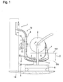
- Fig. 1 shows a crimping machine, comprising a driven by a first motor crimping tool 1 and a supply roll 2, on which a metallic contact element band 3 and a separation strip 4 deposited thereon are wound together to form a spiral, wherein the crimping train 1 assigned a collection device for clocked retraction of the contact element band 3 is.
- the sensor 5 can switch on the second motor 11 for a limited time, if the sag D of the contact element band 3 falls below an arbitrarily definable, lower limit GU, so that again a freely sagging, tension-free loop of the contact element band 3 is formed ,
- the extraction device 11 is in the design after Fig. 1 formed by a pair of take-off rollers 13 which are driven by the second motor 11 and pressed by the opposite sides of the separating strip 4 and are rotatable in opposite directions.
- the separating strip 4 is either fed directly from the gap of the withdrawal rollers 13 into a pneumatic extraction device or deposited in a waste container.
- the contact element tire 3 is withdrawn from the supply roll and transferred to the hanging storage 6. This is done independently of the drive of the crimping device.
- the second motor 11 forms part of the machine stand 14 of the crimping device and is actuated independently of the power stroke of the crimping tool 1 and only to fill the hanging memory 6.
- the switch-on frequency is considerably reduced. It is ensured in any case that no tensile forces can be transmitted to the crimping tool 1 via the contact element band 3.
- the second motor 11 is signal-controlled by the sensor 5 is actuated such that the contact element band 3 in the intermediate zone between the supply roll 2 and the crimping tool 1 is always free of tensile stresses. Due to the contact element band 3, therefore, no forces can be transmitted to the crimping tool 1, which are caused by the removal of the contact element band 3 from the supply roll 2.
- the contact element band 3 is accommodated in a suspended memory 6 in a freely hanging manner in the intermediate zone between the supply roll 2 and the crimping tool 1. It is very flexible and of very low weight in the relevant section. Vibration technology, the crimping tool 1 is therefore completely isolated from the supply roll.
- the sensor 5 is in the design after Fig. 1 formed by a pivotable measuring sensor, which is placed from above on the U - shaped sagging portion of the contact element band 3 and contacts the contact element band with a rotatable roller.
- the sensor 5 is configured to turn on the second motor 11 when the slack D of the contact element band 3 falls below an arbitrarily set lower limit value GU and turns off when the slack D exceeds an arbitrarily definable upper limit value GO.
- the senor 5 can also comprise at least one light barrier and / or a static contact for a control voltage.
- the sensor 5 may further be formed by a closing contact for a control voltage, wherein the closing contact comprises at least one input 7, which is arranged at the lowest point GU of the hanging memory 6 and may be formed by a metallic trough, with which the metallic and electrically conductive contact element strip 3 engages when filling the hanging memory 6.
- the output is formed by the contact element band 3, which can be lowered by the second motor 5 to the input 7.
- the forwarding of the signal thus obtained is expediently carried out via a plug-in contact 9, by which the trolley is connected to the crimping machine.
- the input 7 can thus be formed by a baffle, to which the contact element band 3 can be lowered by the second motor 11.
- a baffle has the advantage that snagging of the contact element band is excluded under all circumstances.
- Fig. 2 shows a design in which the extraction device 10 is formed for the separating strip 4 by a coil 12, on which the separating strip 4 wound and subsequently removed and disposed of.
- tensile forces are transmitted only indirectly via the separating strip in the supply roll 2 and not on the contact element band 3 itself. Due to the indirect transfer of the forces required to unwind the contact element band forces on the supply roll 2 by means of a deformable and limited stretchable strip 4 made of paper results in each of such a strong damping when switching the trigger device 11 in that no disturbing vibrations or forces can be transmitted to the crimping tool 1.
- the paper strip 4 presses in the introduction of tensile forces in the vertically projecting tabs and other vertically projecting parts and plastically deformed, which with an energy destruction is connected. Furthermore, a large length and a high extensibility of the separating strip has a positive effect on the avoidance of an undesired vibration transmission from the supply roll 2 to the crimping tool 1. In this case, it must be ensured that the tensile strength of the separating strip 4 is sufficiently large for reliable unwinding of the contact element strip 3 from the supply roll.
- the supply roll 2 with the contact element band 3 and parting strip 4 spirally wound thereon is rotatable in both designs and mounted in a freely displaceable carriage 8 in an easily exchangeable manner.
- the carriage includes only the storage for the supply roll 2, a handle for facilitating moving and the formed by a curved baffle, electrical input 7 of the sensor 5 and a plug contact element of the connector 9, which is engageable with a mating contact socket of the crimping machine ,
- the cart is accordingly very inexpensive to produce and easy to move manually. It can be stored in large numbers in a warehouse, which also saves the need to manually transport heavy supply rolls 2 and insert them manually into the various crimping machines.
Landscapes
- Engineering & Computer Science (AREA)
- Manufacturing & Machinery (AREA)
- Manufacturing Of Electrical Connectors (AREA)
- Controlling Rewinding, Feeding, Winding, Or Abnormalities Of Webs (AREA)
Priority Applications (1)
| Application Number | Priority Date | Filing Date | Title |
|---|---|---|---|
| PL09171078T PL2169783T3 (pl) | 2008-09-25 | 2009-09-23 | Automat do obciskania |
Applications Claiming Priority (1)
| Application Number | Priority Date | Filing Date | Title |
|---|---|---|---|
| DE102008049021A DE102008049021B4 (de) | 2008-09-25 | 2008-09-25 | Crimpautomat |
Publications (3)
| Publication Number | Publication Date |
|---|---|
| EP2169783A2 EP2169783A2 (de) | 2010-03-31 |
| EP2169783A3 EP2169783A3 (de) | 2013-04-17 |
| EP2169783B1 true EP2169783B1 (de) | 2014-09-17 |
Family
ID=41338700
Family Applications (1)
| Application Number | Title | Priority Date | Filing Date |
|---|---|---|---|
| EP09171078.0A Active EP2169783B1 (de) | 2008-09-25 | 2009-09-23 | Crimpautomat |
Country Status (4)
| Country | Link |
|---|---|
| EP (1) | EP2169783B1 (pl) |
| DE (1) | DE102008049021B4 (pl) |
| ES (1) | ES2524467T3 (pl) |
| PL (1) | PL2169783T3 (pl) |
Families Citing this family (1)
| Publication number | Priority date | Publication date | Assignee | Title |
|---|---|---|---|---|
| DE202011107870U1 (de) | 2011-11-14 | 2013-02-18 | Schäfer Werkzeug- und Sondermaschinenbau GmbH | Variable Zuführeinrichtung für ein Crimpaggregat |
Family Cites Families (9)
| Publication number | Priority date | Publication date | Assignee | Title |
|---|---|---|---|---|
| US4363167A (en) * | 1980-08-11 | 1982-12-14 | Amp Incorporated | Method of terminating leading ends of a plurality of wires |
| JPS6428154A (en) * | 1987-07-20 | 1989-01-30 | Japan Aviation Electron | Chained part taking-up device |
| JP2592678Y2 (ja) * | 1993-06-11 | 1999-03-24 | 住友電装株式会社 | 端子帯供給装置 |
| JP3653934B2 (ja) * | 1997-06-09 | 2005-06-02 | 住友電装株式会社 | 端子リールの変形矯正装置 |
| FR2820601A1 (fr) * | 2001-01-23 | 2002-08-09 | Fci Automotive France | Dispositif d'amenee de connecteurs et station de sertissage munie d'un tel dispositif |
| US6530511B2 (en) * | 2001-02-13 | 2003-03-11 | Medallion Technology, Llc | Wire feed mechanism and method used for fabricating electrical connectors |
| DE102004057818B3 (de) * | 2004-12-01 | 2006-08-03 | Schäfer Werkzeug- und Sondermaschinenbau GmbH | Vorrichtung zum halb- oder vollautomatischen Anbringen eines Kontaktelementes an einem Kabelende |
| US20060172610A1 (en) * | 2005-02-01 | 2006-08-03 | Keisuke Sakai | Method and apparatus for terminal row insert molding |
| JP2008547167A (ja) * | 2005-06-23 | 2008-12-25 | シュロニガー ホールディング アーゲー | 様々な圧着処理やプレス処理を行う圧着機であり、特にはケーブルアッセンブリのための圧着機 |
-
2008
- 2008-09-25 DE DE102008049021A patent/DE102008049021B4/de not_active Expired - Fee Related
-
2009
- 2009-09-23 PL PL09171078T patent/PL2169783T3/pl unknown
- 2009-09-23 ES ES09171078.0T patent/ES2524467T3/es active Active
- 2009-09-23 EP EP09171078.0A patent/EP2169783B1/de active Active
Also Published As
| Publication number | Publication date |
|---|---|
| EP2169783A2 (de) | 2010-03-31 |
| ES2524467T3 (es) | 2014-12-09 |
| DE102008049021B4 (de) | 2013-10-24 |
| PL2169783T3 (pl) | 2015-03-31 |
| EP2169783A3 (de) | 2013-04-17 |
| DE102008049021A1 (de) | 2010-04-01 |
Similar Documents
| Publication | Publication Date | Title |
|---|---|---|
| EP2399715B1 (de) | Ablage- und Nutzentrennstation für eine Bogenstanzmaschine | |
| EP2666216B1 (de) | Anordnung und verfahren zur arretierung einer aufrollautomatik eines ladekabels für ein elektrofahrzeug | |
| EP2873499B1 (de) | Schneidvorrichtung zum Schneiden eines dünnen und klebrigen Bandes, insbesondere eines Cordbandes | |
| EP3257117B1 (de) | Crimpmaschine | |
| EP2452790B1 (de) | Bearbeitungsstation für eine Stanzmaschine und Verfahren zur Probebogenauslage | |
| EP2722141B1 (de) | Vorrichtung für eine Flachbettstanze und Verfahren zum Zuführen einer Bedruckstoffbahn | |
| EP2738886A1 (de) | Anordnung und Verfahren zur Herstellung einer Crimpverbindung | |
| DE102012020360A1 (de) | Stanzmaschine mit Überwachungssensor und Verfahren zum Schnellabschalten einer solchen Maschine | |
| EP2592703B1 (de) | Variable Zuführeinrichtung für ein Crimpaggregat | |
| EP3666700A1 (de) | Vorrichtung zum aufwickeln und wickelwechsel von bahnförmigem material und ein verfahren dafür | |
| EP0995684A2 (de) | Vorrichtung zum Einschieben von Produkten in ein Verpackungsbehältnis | |
| EP2169783B1 (de) | Crimpautomat | |
| DE102011083400B4 (de) | Verfahren und Lagereinrichtung mit Überlasterkennung | |
| EP3157850B1 (de) | Halte- und abrollvorrichtung für auf rollen gewickeltes flach- und/oder folienmaterial, behälterverpackungsanlage und verfahren zum wechseln einer rolle mit flach- und/oder folienmaterial | |
| EP2165954B1 (de) | Bogenverarbeitungsmaschine und Verfahren zum Ablegen von Bogen | |
| EP3060484B1 (de) | Vorrichtung und verfahren zum wechseln von bonrollen einer etikettiermaschine | |
| EP1640273B1 (de) | Wickelvorrichtung zur Entfernung von aufgeschnittenem Bindematerial | |
| DE202008018389U1 (de) | Crimpautomat | |
| EP1975967A1 (de) | Schaltgerät mit einer Einrichtung zur drahtlosen Übertragung einer Gerätezustandsinformation | |
| EP2412497A1 (de) | Vorrichtung und Verfahen zum Wechseln des Oberwerkzeugs einer Stanzstation einer Bogenstanzmaschine | |
| EP3819036B1 (de) | Vorrichtung zum wickeln von bandförmigem material | |
| DE202010017139U1 (de) | Crimpmaschine für unterschiedliche Crimp- und Pressprozesse, insbesondere zur Kabelkonfektionierung | |
| DE202006020927U1 (de) | Crimpmaschine für verschiedene Crimp- und Pressprozesse, insbesondere zur Kabelmontage | |
| DE102011080017B3 (de) | Vorrichtung zur Aufnahme und zum Abspulen mindestens einer Drahtrolle, damit ausgestattete metallurgische Anlage sowie Verfahren zum Abspulen von Draht | |
| DE102006041843B3 (de) | Crimpvorrichtung |
Legal Events
| Date | Code | Title | Description |
|---|---|---|---|
| PUAI | Public reference made under article 153(3) epc to a published international application that has entered the european phase |
Free format text: ORIGINAL CODE: 0009012 |
|
| 17P | Request for examination filed |
Effective date: 20090923 |
|
| AK | Designated contracting states |
Kind code of ref document: A2 Designated state(s): AT BE BG CH CY CZ DE DK EE ES FI FR GB GR HR HU IE IS IT LI LT LU LV MC MK MT NL NO PL PT RO SE SI SK SM TR |
|
| AX | Request for extension of the european patent |
Extension state: AL BA RS |
|
| PUAL | Search report despatched |
Free format text: ORIGINAL CODE: 0009013 |
|
| AK | Designated contracting states |
Kind code of ref document: A3 Designated state(s): AT BE BG CH CY CZ DE DK EE ES FI FR GB GR HR HU IE IS IT LI LT LU LV MC MK MT NL NO PL PT RO SE SI SK SM TR |
|
| AX | Request for extension of the european patent |
Extension state: AL BA RS |
|
| RIC1 | Information provided on ipc code assigned before grant |
Ipc: H01R 43/055 20060101AFI20130314BHEP |
|
| RBV | Designated contracting states (corrected) |
Designated state(s): AT BE BG CH CY CZ DE DK EE ES FI FR GB GR HR HU IE IS IT LI LT LU LV MC MK MT NL NO PL PT RO SE SI SK SM TR |
|
| GRAP | Despatch of communication of intention to grant a patent |
Free format text: ORIGINAL CODE: EPIDOSNIGR1 |
|
| INTG | Intention to grant announced |
Effective date: 20140331 |
|
| GRAS | Grant fee paid |
Free format text: ORIGINAL CODE: EPIDOSNIGR3 |
|
| GRAA | (expected) grant |
Free format text: ORIGINAL CODE: 0009210 |
|
| AK | Designated contracting states |
Kind code of ref document: B1 Designated state(s): AT BE BG CH CY CZ DK EE ES FI FR GB GR HR HU IE IS IT LI LT LU LV MC MK MT NL NO PL PT RO SE SI SK SM TR |
|
| RBV | Designated contracting states (corrected) |
Designated state(s): AT BE BG CH CY CZ DK EE ES FI FR GB GR HR HU IE IS IT LI LT LU LV MC MK MT NL NO PL PT RO SE SI SK SM TR |
|
| REG | Reference to a national code |
Ref country code: DE Ref legal event code: R108 Ref country code: GB Ref legal event code: FG4D Free format text: NOT ENGLISH |
|
| REG | Reference to a national code |
Ref country code: CH Ref legal event code: EP |
|
| REG | Reference to a national code |
Ref country code: IE Ref legal event code: FG4D Free format text: LANGUAGE OF EP DOCUMENT: GERMAN |
|
| REG | Reference to a national code |
Ref country code: AT Ref legal event code: REF Ref document number: 688065 Country of ref document: AT Kind code of ref document: T Effective date: 20141015 |
|
| REG | Reference to a national code |
Ref country code: DE Ref legal event code: R108 Effective date: 20140917 |
|
| REG | Reference to a national code |
Ref country code: RO Ref legal event code: EPE |
|
| REG | Reference to a national code |
Ref country code: ES Ref legal event code: FG2A Ref document number: 2524467 Country of ref document: ES Kind code of ref document: T3 Effective date: 20141209 |
|
| REG | Reference to a national code |
Ref country code: CH Ref legal event code: NV Representative=s name: SCHNEIDER FELDMANN AG PATENT- UND MARKENANWAEL, CH |
|
| PG25 | Lapsed in a contracting state [announced via postgrant information from national office to epo] |
Ref country code: FI Free format text: LAPSE BECAUSE OF FAILURE TO SUBMIT A TRANSLATION OF THE DESCRIPTION OR TO PAY THE FEE WITHIN THE PRESCRIBED TIME-LIMIT Effective date: 20140917 Ref country code: GR Free format text: LAPSE BECAUSE OF FAILURE TO SUBMIT A TRANSLATION OF THE DESCRIPTION OR TO PAY THE FEE WITHIN THE PRESCRIBED TIME-LIMIT Effective date: 20141218 Ref country code: SE Free format text: LAPSE BECAUSE OF FAILURE TO SUBMIT A TRANSLATION OF THE DESCRIPTION OR TO PAY THE FEE WITHIN THE PRESCRIBED TIME-LIMIT Effective date: 20140917 Ref country code: LT Free format text: LAPSE BECAUSE OF FAILURE TO SUBMIT A TRANSLATION OF THE DESCRIPTION OR TO PAY THE FEE WITHIN THE PRESCRIBED TIME-LIMIT Effective date: 20140917 Ref country code: NO Free format text: LAPSE BECAUSE OF FAILURE TO SUBMIT A TRANSLATION OF THE DESCRIPTION OR TO PAY THE FEE WITHIN THE PRESCRIBED TIME-LIMIT Effective date: 20141217 |
|
| REG | Reference to a national code |
Ref country code: NL Ref legal event code: VDEP Effective date: 20140917 |
|
| REG | Reference to a national code |
Ref country code: LT Ref legal event code: MG4D |
|
| PG25 | Lapsed in a contracting state [announced via postgrant information from national office to epo] |
Ref country code: CY Free format text: LAPSE BECAUSE OF FAILURE TO SUBMIT A TRANSLATION OF THE DESCRIPTION OR TO PAY THE FEE WITHIN THE PRESCRIBED TIME-LIMIT Effective date: 20140917 Ref country code: LV Free format text: LAPSE BECAUSE OF FAILURE TO SUBMIT A TRANSLATION OF THE DESCRIPTION OR TO PAY THE FEE WITHIN THE PRESCRIBED TIME-LIMIT Effective date: 20140917 Ref country code: HR Free format text: LAPSE BECAUSE OF FAILURE TO SUBMIT A TRANSLATION OF THE DESCRIPTION OR TO PAY THE FEE WITHIN THE PRESCRIBED TIME-LIMIT Effective date: 20140917 |
|
| PG25 | Lapsed in a contracting state [announced via postgrant information from national office to epo] |
Ref country code: NL Free format text: LAPSE BECAUSE OF FAILURE TO SUBMIT A TRANSLATION OF THE DESCRIPTION OR TO PAY THE FEE WITHIN THE PRESCRIBED TIME-LIMIT Effective date: 20140917 |
|
| REG | Reference to a national code |
Ref country code: PL Ref legal event code: T3 |
|
| PG25 | Lapsed in a contracting state [announced via postgrant information from national office to epo] |
Ref country code: PT Free format text: LAPSE BECAUSE OF FAILURE TO SUBMIT A TRANSLATION OF THE DESCRIPTION OR TO PAY THE FEE WITHIN THE PRESCRIBED TIME-LIMIT Effective date: 20150119 Ref country code: IS Free format text: LAPSE BECAUSE OF FAILURE TO SUBMIT A TRANSLATION OF THE DESCRIPTION OR TO PAY THE FEE WITHIN THE PRESCRIBED TIME-LIMIT Effective date: 20150117 Ref country code: CZ Free format text: LAPSE BECAUSE OF FAILURE TO SUBMIT A TRANSLATION OF THE DESCRIPTION OR TO PAY THE FEE WITHIN THE PRESCRIBED TIME-LIMIT Effective date: 20140917 Ref country code: EE Free format text: LAPSE BECAUSE OF FAILURE TO SUBMIT A TRANSLATION OF THE DESCRIPTION OR TO PAY THE FEE WITHIN THE PRESCRIBED TIME-LIMIT Effective date: 20140917 Ref country code: SK Free format text: LAPSE BECAUSE OF FAILURE TO SUBMIT A TRANSLATION OF THE DESCRIPTION OR TO PAY THE FEE WITHIN THE PRESCRIBED TIME-LIMIT Effective date: 20140917 |
|
| REG | Reference to a national code |
Ref country code: IE Ref legal event code: MM4A |
|
| PG25 | Lapsed in a contracting state [announced via postgrant information from national office to epo] |
Ref country code: BE Free format text: LAPSE BECAUSE OF NON-PAYMENT OF DUE FEES Effective date: 20140930 Ref country code: MC Free format text: LAPSE BECAUSE OF FAILURE TO SUBMIT A TRANSLATION OF THE DESCRIPTION OR TO PAY THE FEE WITHIN THE PRESCRIBED TIME-LIMIT Effective date: 20140917 |
|
| PLBE | No opposition filed within time limit |
Free format text: ORIGINAL CODE: 0009261 |
|
| STAA | Information on the status of an ep patent application or granted ep patent |
Free format text: STATUS: NO OPPOSITION FILED WITHIN TIME LIMIT |
|
| PG25 | Lapsed in a contracting state [announced via postgrant information from national office to epo] |
Ref country code: DK Free format text: LAPSE BECAUSE OF FAILURE TO SUBMIT A TRANSLATION OF THE DESCRIPTION OR TO PAY THE FEE WITHIN THE PRESCRIBED TIME-LIMIT Effective date: 20140917 |
|
| 26N | No opposition filed |
Effective date: 20150618 |
|
| PG25 | Lapsed in a contracting state [announced via postgrant information from national office to epo] |
Ref country code: IE Free format text: LAPSE BECAUSE OF NON-PAYMENT OF DUE FEES Effective date: 20140923 |
|
| REG | Reference to a national code |
Ref country code: AT Ref legal event code: MM01 Ref document number: 688065 Country of ref document: AT Kind code of ref document: T Effective date: 20140923 |
|
| PG25 | Lapsed in a contracting state [announced via postgrant information from national office to epo] |
Ref country code: SI Free format text: LAPSE BECAUSE OF FAILURE TO SUBMIT A TRANSLATION OF THE DESCRIPTION OR TO PAY THE FEE WITHIN THE PRESCRIBED TIME-LIMIT Effective date: 20140917 |
|
| PG25 | Lapsed in a contracting state [announced via postgrant information from national office to epo] |
Ref country code: AT Free format text: LAPSE BECAUSE OF NON-PAYMENT OF DUE FEES Effective date: 20140923 |
|
| PG25 | Lapsed in a contracting state [announced via postgrant information from national office to epo] |
Ref country code: SM Free format text: LAPSE BECAUSE OF FAILURE TO SUBMIT A TRANSLATION OF THE DESCRIPTION OR TO PAY THE FEE WITHIN THE PRESCRIBED TIME-LIMIT Effective date: 20140917 |
|
| PG25 | Lapsed in a contracting state [announced via postgrant information from national office to epo] |
Ref country code: MT Free format text: LAPSE BECAUSE OF FAILURE TO SUBMIT A TRANSLATION OF THE DESCRIPTION OR TO PAY THE FEE WITHIN THE PRESCRIBED TIME-LIMIT Effective date: 20140917 Ref country code: BG Free format text: LAPSE BECAUSE OF FAILURE TO SUBMIT A TRANSLATION OF THE DESCRIPTION OR TO PAY THE FEE WITHIN THE PRESCRIBED TIME-LIMIT Effective date: 20140917 |
|
| PG25 | Lapsed in a contracting state [announced via postgrant information from national office to epo] |
Ref country code: LU Free format text: LAPSE BECAUSE OF NON-PAYMENT OF DUE FEES Effective date: 20140923 Ref country code: TR Free format text: LAPSE BECAUSE OF FAILURE TO SUBMIT A TRANSLATION OF THE DESCRIPTION OR TO PAY THE FEE WITHIN THE PRESCRIBED TIME-LIMIT Effective date: 20140917 Ref country code: HU Free format text: LAPSE BECAUSE OF FAILURE TO SUBMIT A TRANSLATION OF THE DESCRIPTION OR TO PAY THE FEE WITHIN THE PRESCRIBED TIME-LIMIT; INVALID AB INITIO Effective date: 20090923 |
|
| REG | Reference to a national code |
Ref country code: FR Ref legal event code: PLFP Year of fee payment: 8 |
|
| REG | Reference to a national code |
Ref country code: FR Ref legal event code: PLFP Year of fee payment: 9 |
|
| PG25 | Lapsed in a contracting state [announced via postgrant information from national office to epo] |
Ref country code: MK Free format text: LAPSE BECAUSE OF FAILURE TO SUBMIT A TRANSLATION OF THE DESCRIPTION OR TO PAY THE FEE WITHIN THE PRESCRIBED TIME-LIMIT Effective date: 20140917 |
|
| REG | Reference to a national code |
Ref country code: FR Ref legal event code: PLFP Year of fee payment: 10 |
|
| PGFP | Annual fee paid to national office [announced via postgrant information from national office to epo] |
Ref country code: GB Payment date: 20190830 Year of fee payment: 11 |
|
| PGFP | Annual fee paid to national office [announced via postgrant information from national office to epo] |
Ref country code: ES Payment date: 20191007 Year of fee payment: 11 |
|
| REG | Reference to a national code |
Ref country code: CH Ref legal event code: PFA Owner name: SCHAEFER WERKZEUG- UND SONDERMASCHINENBAU GMBH, DE Free format text: FORMER OWNER: SCHAEFER WERKZEUG- UND SONDERMASCHINENBAU GMBH, DE |
|
| GBPC | Gb: european patent ceased through non-payment of renewal fee |
Effective date: 20200923 |
|
| PG25 | Lapsed in a contracting state [announced via postgrant information from national office to epo] |
Ref country code: GB Free format text: LAPSE BECAUSE OF NON-PAYMENT OF DUE FEES Effective date: 20200923 |
|
| REG | Reference to a national code |
Ref country code: ES Ref legal event code: FD2A Effective date: 20220118 |
|
| PG25 | Lapsed in a contracting state [announced via postgrant information from national office to epo] |
Ref country code: ES Free format text: LAPSE BECAUSE OF NON-PAYMENT OF DUE FEES Effective date: 20200924 |
|
| PGFP | Annual fee paid to national office [announced via postgrant information from national office to epo] |
Ref country code: RO Payment date: 20220916 Year of fee payment: 14 |
|
| PGFP | Annual fee paid to national office [announced via postgrant information from national office to epo] |
Ref country code: PL Payment date: 20220822 Year of fee payment: 14 Ref country code: FR Payment date: 20220919 Year of fee payment: 14 |
|
| PGFP | Annual fee paid to national office [announced via postgrant information from national office to epo] |
Ref country code: IT Payment date: 20220921 Year of fee payment: 14 |
|
| PGFP | Annual fee paid to national office [announced via postgrant information from national office to epo] |
Ref country code: CH Payment date: 20220912 Year of fee payment: 14 |
|
| PG25 | Lapsed in a contracting state [announced via postgrant information from national office to epo] |
Ref country code: RO Free format text: LAPSE BECAUSE OF NON-PAYMENT OF DUE FEES Effective date: 20230923 |
|
| REG | Reference to a national code |
Ref country code: CH Ref legal event code: PL |
|
| PG25 | Lapsed in a contracting state [announced via postgrant information from national office to epo] |
Ref country code: CH Free format text: LAPSE BECAUSE OF NON-PAYMENT OF DUE FEES Effective date: 20230930 |
|
| PG25 | Lapsed in a contracting state [announced via postgrant information from national office to epo] |
Ref country code: FR Free format text: LAPSE BECAUSE OF NON-PAYMENT OF DUE FEES Effective date: 20230930 Ref country code: CH Free format text: LAPSE BECAUSE OF NON-PAYMENT OF DUE FEES Effective date: 20230930 |
|
| PG25 | Lapsed in a contracting state [announced via postgrant information from national office to epo] |
Ref country code: PL Free format text: LAPSE BECAUSE OF NON-PAYMENT OF DUE FEES Effective date: 20230923 |
|
| PG25 | Lapsed in a contracting state [announced via postgrant information from national office to epo] |
Ref country code: PL Free format text: LAPSE BECAUSE OF NON-PAYMENT OF DUE FEES Effective date: 20230923 |
|
| PG25 | Lapsed in a contracting state [announced via postgrant information from national office to epo] |
Ref country code: IT Free format text: LAPSE BECAUSE OF NON-PAYMENT OF DUE FEES Effective date: 20230923 |
|
| PG25 | Lapsed in a contracting state [announced via postgrant information from national office to epo] |
Ref country code: IT Free format text: LAPSE BECAUSE OF NON-PAYMENT OF DUE FEES Effective date: 20230923 |