EP2169531B1 - Device driver installer and installation method - Google Patents
Device driver installer and installation method Download PDFInfo
- Publication number
- EP2169531B1 EP2169531B1 EP09169341.6A EP09169341A EP2169531B1 EP 2169531 B1 EP2169531 B1 EP 2169531B1 EP 09169341 A EP09169341 A EP 09169341A EP 2169531 B1 EP2169531 B1 EP 2169531B1
- Authority
- EP
- European Patent Office
- Prior art keywords
- function
- image forming
- type
- device driver
- information
- Prior art date
- Legal status (The legal status is an assumption and is not a legal conclusion. Google has not performed a legal analysis and makes no representation as to the accuracy of the status listed.)
- Active
Links
Images


Classifications
-
- G—PHYSICS
- G06—COMPUTING OR CALCULATING; COUNTING
- G06F—ELECTRIC DIGITAL DATA PROCESSING
- G06F3/00—Input arrangements for transferring data to be processed into a form capable of being handled by the computer; Output arrangements for transferring data from processing unit to output unit, e.g. interface arrangements
- G06F3/12—Digital output to print unit, e.g. line printer, chain printer
- G06F3/1201—Dedicated interfaces to print systems
- G06F3/1202—Dedicated interfaces to print systems specifically adapted to achieve a particular effect
- G06F3/1203—Improving or facilitating administration, e.g. print management
- G06F3/1204—Improving or facilitating administration, e.g. print management resulting in reduced user or operator actions, e.g. presetting, automatic actions, using hardware token storing data
-
- G—PHYSICS
- G06—COMPUTING OR CALCULATING; COUNTING
- G06F—ELECTRIC DIGITAL DATA PROCESSING
- G06F3/00—Input arrangements for transferring data to be processed into a form capable of being handled by the computer; Output arrangements for transferring data from processing unit to output unit, e.g. interface arrangements
- G06F3/12—Digital output to print unit, e.g. line printer, chain printer
- G06F3/1201—Dedicated interfaces to print systems
- G06F3/1223—Dedicated interfaces to print systems specifically adapted to use a particular technique
- G06F3/1224—Client or server resources management
- G06F3/1225—Software update, e.g. print driver, modules, plug-ins, fonts
-
- G—PHYSICS
- G06—COMPUTING OR CALCULATING; COUNTING
- G06F—ELECTRIC DIGITAL DATA PROCESSING
- G06F3/00—Input arrangements for transferring data to be processed into a form capable of being handled by the computer; Output arrangements for transferring data from processing unit to output unit, e.g. interface arrangements
- G06F3/12—Digital output to print unit, e.g. line printer, chain printer
- G06F3/1201—Dedicated interfaces to print systems
- G06F3/1223—Dedicated interfaces to print systems specifically adapted to use a particular technique
- G06F3/1224—Client or server resources management
- G06F3/1228—Printing driverless or using generic drivers
-
- G—PHYSICS
- G06—COMPUTING OR CALCULATING; COUNTING
- G06F—ELECTRIC DIGITAL DATA PROCESSING
- G06F3/00—Input arrangements for transferring data to be processed into a form capable of being handled by the computer; Output arrangements for transferring data from processing unit to output unit, e.g. interface arrangements
- G06F3/12—Digital output to print unit, e.g. line printer, chain printer
- G06F3/1201—Dedicated interfaces to print systems
- G06F3/1223—Dedicated interfaces to print systems specifically adapted to use a particular technique
- G06F3/1229—Printer resources management or printer maintenance, e.g. device status, power levels
- G06F3/1232—Transmitting printer device capabilities, e.g. upon request or periodically
Definitions
- the present invention relates to a device driver installer and an installation method which install, in an information processing apparatus, a device driver to control an image processing apparatus.
- An information processing apparatus such as a computer normally uses a device driver to control an image forming apparatus such as a printer or an MFP (Multi Function Peripheral) and make it execute processing such as printing.
- a device driver is software having a function of controlling an image forming apparatus and installed in an information processing apparatus as needed. Since image forming apparatuses have different functions depending on their types, device drivers for controlling them need to be developed and provided in accordance with the apparatus types. Developing device drivers and distributing them to users are very burdensome for any manufacturer which develops many kinds of image forming apparatuses.
- the generic device driver has a plurality of control functions corresponding to a plurality of kinds of image forming apparatuses.
- the generic device driver is preferably configured to permit customization according to the functions of an image forming apparatus to be controlled.
- the generic device driver is also preferably automatically customized for an image forming apparatus as a control target and installed in an information processing apparatus without making the user select the control functions.
- a generic printer driver extracts configuration data from a printing apparatus, stores it in a nonvolatile storage device, and automatically customizes itself in accordance with the configuration data.
- the generic device driver customizes itself by acquiring function information from an image forming apparatus. However, if the function information transfer amount is limited, the function information cannot completely be transferred, or transfer takes a long time.
- Document US 2004/223182 A1 discloses an information processing method for an information processing apparatus which makes connection to a network to which at least a client apparatus and a printer are connected that causes a computer to execute: a printer management step of managing information on the printer; a printer driver management step of managing a printer driver for the printer for which the information is managed; a client management step of managing the client apparatus; and an install step of installing the printer driver in the client apparatus which has issued an install request for the printer driver.
- the present invention has been made in consideration of the above-described related art, and has as its object to provide a device driver installer and an installation method which reduce the burden on both the developing side and the use side by applying a generic device driver to a plurality of kinds of image forming apparatuses. It is another object to provide a device driver installer and an installation method which enable a generic device driver to provide even functions having an exclusive relationship. It is still another object to provide a device driver installer and an installation method which appropriately customize a device driver in a short time for an image forming apparatus to be used. It is still another object to provide a device driver installer and an installation method which install a device driver even if an image forming apparatus to be used is unrecognizable.
- an information processing apparatus as defined in claim 1.
- the present invention obviates the need for developing and maintaining different device drivers for respective image forming apparatuses and lightens the burden on both the device driver provider and the device driver user.
- the functions of an image forming apparatus are transferred using a type ID with a small data amount. This makes it possible to acquire information necessary for customization from the image forming apparatus using an information transfer method capable of transferring only a small quantity of data, for example, information transfer using USB On PID.
- FIG. 1 is a block diagram showing an example of the arrangement of an image forming system according to the first embodiment of the present invention.
- apparatuses included in the image forming system of this embodiment are connected via a network 107.
- the network 107 can have either one system or a plurality of systems.
- client computers 101, 102, and 103 are information processing apparatuses having a function of communicating with image forming apparatuses such as a printer and a digital MFP (Mullti Function Peripheral) connected to the network 107.
- Software programs such as an operating system, device drivers for controlling image forming apparatuses, and image forming applications can be installed in each information processing apparatus.
- an image forming apparatus 104 is image forming apparatus A.
- An image forming apparatus 105 is image forming apparatus B.
- An image forming apparatus 106 is image forming apparatus C.
- An image forming apparatus according to this embodiment is an MFP having at least an image data print function, a laser printer, or an inkjet printer. Each image forming apparatus has a function of receiving digital data from a client computer and executing print processing.
- the image forming apparatus 104 is of the first type, which has the following functions and is designed to be controllable by a device control instruction set of type A.
- the type ID is expressed by series ID + group ID.
- Each of the series ID and group ID is represented by a 1-byte letter in uppercase.
- the series ID of image forming apparatus A is A
- the group ID is A.
- the type ID is AA.
- the series ID represents an image forming apparatus series to which the image forming apparatus belongs.
- the series ID is used as information to specify a generic device driver usable to control the image forming apparatus.
- the image forming apparatus series is defined in accordance with the type of two-way communication function of each image forming apparatus.
- the group ID represents a function group of image forming apparatuses.
- the group ID is used as customization information to specify how to customize the generic device driver to be used to control the image forming apparatus.
- the group ID is defined in accordance with the functions of each image forming apparatus within the series to which the image forming apparatus belongs.
- the type ID is information to specify the functional arrangement of each image forming apparatus.
- type ID may contain only the series ID or group ID in other embodiments.
- the image forming apparatus B 105 is of the second type, which has the following functions and is designed to be controllable by the device control instruction set of type A.
- the image forming apparatus B 105 is an old model and therefore has no function of communicating with a client PC and notifying it of a type ID generated in accordance with the functional arrangement of its own.
- the image forming apparatus C 106 is of the third type, which has the following functions and is designed to be controllable by a device control instruction set of type D.
- the series ID of image forming apparatus C is D, the group ID is D, and the type ID is DD.
- the device control instruction set of type D includes a device control instruction set of type C.
- the two-way communication function of type D includes a two-way communication function of type C.
- Fig. 2 is a block diagram showing the internal arrangement of the client PC.
- the client PC has an external AC adapter 201 as the power supply.
- the client PC incorporates the following units:
- the power supply unit 202 supplies power to the respective units.
- the CPU (Central Processing Unit) 203 is responsible for main control.
- the BIOS 204 is a program to give instructions for basic control.
- the BIOS 204 is recorded in a ROM.
- the hard disk controller (HDC) 209 controls the hard disk drive (HDD) 208 which is a recordable nonvolatile memory device.
- the CPU reads out a software program from the hard disk drive 208, expands it on the main memory 212, and executes the program using the main memory 212.
- screen display is done by causing the video controller (VGAC) 206 to display, on the display 205, characters and the like written in the video memory (VRAM) 207.
- VGAC video controller
- a user operation is performed by key input from the keyboard 213.
- the keyboard controller (KBC) 211 processes the received key input information.
- the network port 210 performs network communication with the image forming apparatuses connected to the network.
- Software programs such as an OS (Operating System), various kinds of applications, device driver installers, and device drivers are recorded in the hard disk drive (HDD) 208 and executed by the CPU 203.
- the device drivers include installed generic device drivers for the image forming apparatuses. The user can execute setup of the image forming system, information acquisition from the image forming apparatuses, and print processing by operating the various kinds of software recorded in the hard disk drive (HDD) 208.
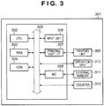
- Fig. 3 is a block diagram showing the internal arrangement of the image forming apparatus according to the first embodiment of the present invention. The arrangement is common to the image forming apparatuses 104 to 106.
- a CPU 302 controls an image forming apparatus 301. Based on, for example, a control program stored in a ROM 304 or an external memory 311, the CPU 302 outputs an image signal as output information to a printing unit (printer engine) 309 connected to a system bus 305 via a printing unit I/F 307.
- the ROM 304 stores the control program of the CPU 302 and the like.
- the font ROM of the ROM 304 stores, for example, font data to be used to generate the output information.
- the data ROM of the ROM 304 stores, for example, information to be used on the host computer if the image forming apparatus does not include the external memory 311 such as a hard disk.
- the CPU 302 can communicate with a client PC via an input unit 306 and notify it of information or the like in the printer.
- a RAM 303 functions as, for example, the main memory or work area of the CPU 302.
- the RAM 303 is designed to be able to increase its memory capacity using an optional RAM connected to an add-on port (not shown).
- the RAM 303 serves as, for example, an output information expansion area, an environment data storage area, and an NVRAM.
- a memory controller (MC) 308 controls access to the external memory 311 formed from a hard disk drive (HDD) or an IC card.
- the external memory 311 stores, for example, font data, an emulation program, and form data in addition to the above-described control program.
- An operation panel 310 includes switches and LED indicators for operations.
- the image forming apparatus 301 also includes a counter 312 which counts the number of printed sheets for charging.
- the CPU 302 can control the counting operation of the counter 312.
- the ROM 304 or the external memory 311 stores the type ID, that is, information to specify the functional arrangement of the image forming apparatus.
- the above-described external memory 311 need not always be one. Alternatively, a plurality of external memories may be connected, which store optional cards and programs for interpreting printer control languages of different language systems in addition to built-in fonts.
- Figs. 4A , 4B, and 4C are views showing the relationship between device drivers and image forming apparatuses according to the present invention.
- reference numeral 104 denotes image forming apparatus A; and 406, image forming apparatus D.
- reference numeral 105 denotes image forming apparatus B; and 409, image forming apparatus E.
- reference numeral 411 denotes image forming apparatus F. The arrangements of the image forming apparatuses A 104 and B 105 have already been described.
- the image forming apparatus D 406 has the following functions and is designed to be controllable by the device control instruction set of type B.
- the image forming apparatus E 409 has the following functions and is designed to be controllable by the device control instruction set of type A.
- the image forming apparatus F 411 has the following functions and is designed to be controllable by the device control instruction set of type C.
- each image forming apparatus belongs to one of an image forming apparatus series A 404, an image forming apparatus series B 407, and an image forming apparatus series C 410.
- the image forming apparatus series are generated by classifying and grouping the image forming apparatuses depending on the type of two-way communication function.
- the two-way communication functions of the image forming apparatuses are classified into three types A, B, and C which have an exclusive relationship. It is therefore impossible to make one device driver have a plurality of two-way communication functions of different types and control the image forming apparatuses by selectively using the functions. For this reason, the image forming apparatuses are classified by the type of two-way communication function. These classifications are the series.
- the image forming apparatuses A 104 and D 406 have the two-way communication function of type A and are therefore classified into the group of type A, thereby forming the image forming apparatus series A 404.
- the image forming apparatuses B 105 and E 409 have the two-way communication function of type B and are so classified into the group of type B, thereby forming the image forming apparatus series B 407.
- the image forming apparatus F 411 has the two-way communication function of type C and is therefore classified into the group of type C, thereby forming the image forming apparatus series C 410.
- a generic device driver A 401 is a device driver for the image forming apparatuses belonging to the image forming apparatus series A 404.
- the generic device driver A 401 has a function of providing a driver UI screen of type A or D to the user, and a function of controlling an image forming apparatus by transmitting the device control instruction set of type A or B to it.
- the generic device driver B 402 is a device driver for the image forming apparatuses belonging to the image forming apparatus series B 407.
- the generic device driver B 402 has a function of providing a driver UI screen of type A or B to the user, and a function of controlling an image forming apparatus by transmitting the device control instruction set of type A to it.
- the generic device driver C 403 is a device driver for the image forming apparatuses belonging to the image forming apparatus series C 410.
- the generic device driver C 403 has a function of providing a driver UI screen of type C to the user, and a function of controlling an image forming apparatus by transmitting the device control instruction set of type C to it.
- Each generic device driver has various kinds of functions conforming to the functions of a plurality of kinds of image forming apparatuses belonging to a corresponding image forming apparatus series, and a function of customizing itself in accordance with the functions of each image forming apparatus. That is, each generic device driver is customized for the image forming apparatuses belonging to the corresponding image forming apparatus series.
- the generic device driver A 401 has the following functions.
- the generic device driver B 402 has the following functions.
- the generic device driver C 403 has the following functions.
- the relationship between the numbers of image forming apparatuses and the number of device drivers is five to three.
- the device drivers and the functions of the plurality of image forming apparatuses belonging to the image forming apparatus series make pairs.
- the generic device drivers A 401, B 402, and C 403 shown in Figs. 4A to 4C are packaged together to form one generic device driver installer.
- the generated generic device driver installer is stored in the hard disk drive (HDD) 208 of the client PC.
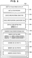
- Fig. 5 is a block diagram showing the arrangement of the generic device driver installer.
- an installation program 501 to be activated in accordance with a user instruction has a function of installing a generic device driver 500 in a client PC. More specifically, the installation function includes the following functions.
- a device specifications converter 502 has a function of converting the identification information of an image forming apparatus into a type ID by referring to a device specifications conversion table 503.
- the device specifications conversion table 503 holds the association information between the identification information and the type ID of an image forming apparatus.
- a default type setting area 504 holds a default series ID and a default group ID which are used when no identifiable type ID is acquired from an image forming apparatus.
- series ID: C and group ID: C are held as default values.
- a generic device driver storage area 505 includes a series ID storage area 506, a generic device driver A 507, a generic device driver B 508, and a generic device driver C 509.
- the series ID storage area 506 stores the association information between the series IDs and the generic device drivers. Referring to the series ID storage area enables to specify one generic device driver corresponding to one series ID.
- the generic device driver A can be specified as the generic device driver suitable for the image forming apparatus series.
- the generic device driver B can be specified as the generic device driver suitable for the image forming apparatus series.
- the generic device driver C can be specified as the generic device driver suitable for the image forming apparatus series.
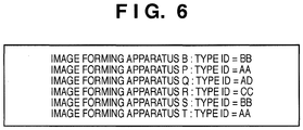
- Fig. 6 is a view showing an example of association information stored in the device specifications conversion table 503.
- the device specifications conversion table stores the identification information and type ID of an image forming apparatus in association with each other.
- type ID BB
- type ID AA
- type ID AD
- type ID CC
- identity information image forming apparatus B
- identity information image forming apparatus P
- identification information image forming apparatus Q
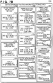
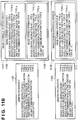
- Figs. 7A-1 , 7A-2 and 7B are views showing details of the generic device drivers stored in the generic device driver storage area 505.
- the generic device drivers are packaged together in the generic device driver installer and stored in the hard disk drive 208 of the client PC.
- One generic device driver includes one generic device driver dependent portion and one generic device driver common portion. There is only one generic device driver common portion common to all generic device drivers.
- one generic device driver dependent portion includes a UI module and a graphic module.
- a generic device driver A dependent portion 701 includes a generic device driver A UI module 702 and a generic device driver A graphic module 703.
- a generic device driver B dependent portion 704 includes a generic device driver B UI module 705 and a generic device driver B graphic module 706.
- a generic device driver C dependent portion 707 includes a generic device driver C UI module 708 and a generic device driver C graphic module 709.
- the generic device driver UI modules 702, 705, and 708 are program modules each of which has a function of changing, in accordance with customization information, the GUI function it should provide to the user.
- the generic device driver graphic modules 703, 706, and 709 are program modules each of which has a function of changing the image forming apparatus control function in accordance with customization information.
- an area 711 stores a type ID specified by the installer at the time of installation and customization information acquired by the generic device driver UI module.
- the area 711 is allocated in a nonvolatile memory. Strictly speaking, the area 711 is not included in the installer (or installation set).
- a specifications provider 712 has a function of providing the customization information and customization function information of a generic device driver in response to a query from the generic device driver UI module and the generic device driver graphic module.
- a customization information storage area 713 holds, in correspondence with each group ID, function information necessary for a device driver to control image forming apparatuses having a specific group ID.
- the customization information storage area 713 holds group A function information necessary for controlling devices having a group ID "A”, group B function information necessary for controlling devices having a group ID "B”, group C function information necessary for controlling devices having a group ID "C”, and group D function information necessary for controlling devices having a group ID "D”.
- the customization information storage area 713 allows addition, editing, and deletion of group ID specific function information any time.
- a device independent function information storage area 714 stores, for each function unit, function information which is independent of the functions of the image forming apparatuses and can be provided by the device drivers.
- the device independent function information storage area 714 includes a driver UI type unit 715.
- the driver UI type unit 715 in the device independent function information storage area 714 stores and manages UI function information the device drivers can provide to the user.
- the driver UI type unit 715 includes type A function information 716, type B function information 717, type C function information 718, and type D function information 719.
- the type A function information 716 sets "UI template 1" as a template, "Japanese” as a resource language, and "type A” as a Bitmap type. This information represents that when displaying a UI, the device driver needs to use UI template 1, Japanese resource information, and type A Bitmap.
- the type B function information 717 sets "UI template 2" as a template, "Japanese” as a resource language, and "type A” as a Bitmap type. This information represents that when displaying a UI, the device driver needs to use UI template 2, Japanese resource information, and type A Bitmap.
- the type C function information 718 sets "UI template 1" as a template, "English” as a resource language, and "type B” as a Bitmap type. This information represents that when displaying a UI, the device driver needs to use UI template 1, English resource information, and type B Bitmap.
- the type D function information 719 sets "UI template 2" as a template, "English” as a resource language, and "type B” as a Bitmap type. This information represents that when displaying a UI, the device driver needs to use UI template 2, English resource information, and type B Bitmap.
- the device independent function information storage area 714 allows addition, editing, and deletion of function units any time.
- a device dependent function information storage area 720 stores, for each function unit, function information which depends on the functions of the image forming apparatuses and can be provided by the device drivers.
- Fig. 7B shows details.
- the device dependent function information storage area 720 includes a device control instruction set unit 721, a paper cassette selecting function unit 725, a paper selecting function unit 729, a color/monochrome print function unit 734, a resolution selecting function unit 737, a finisher selecting function unit 740, and a two-way communication function unit 743.
- the device control instruction set unit 721 stores information about the control instructions of the image forming apparatuses usable by the device drivers.
- the device control instruction set unit 721 includes type A function information 722, type B function information 723, and type C function information 724.
- the type A function information 722 sets "instruction set: A", and "PDL: LIPS1". This information represents that it is necessary to use the instruction set A as a device control instruction and LIPS1 as a print control language.
- the type B function information 723 sets "instruction set: A", and "PDL: LIPS2". This information represents that it is necessary to use the instruction set A as a device control instruction and LIPS2 as a print control language.
- the type C function information 724 sets "instruction set: B", and "PDL: LIPS3". This information represents that it is necessary to use the instruction set B as a device control instruction and LIPS3 as a print control language.
- the paper cassette selecting function unit 725 stores information about the cassette selecting functions of the image forming apparatuses usable by the device drivers.
- the paper cassette selecting function unit 725 includes type A function information 726, type B function information 727, and type C function information 728.
- the type A function information 726 sets "4" as the number of paper cassettes. This information represents that it is possible to make a user select one of four paper cassettes and issue a control instruction to an image forming apparatus so as to print using the cassette.
- the type B function information 727 sets "3" as the number of paper cassettes. This information represents that it is possible to make a user select one of three paper cassettes and issue a control instruction to an image forming apparatus so as to print using the cassette.
- the type C function information 728 sets "1" as the number of paper cassettes. This information represents that it is possible to issue a control instruction to an image forming apparatus so as to print using one cassette.
- the paper selecting function unit 729 stores information about paper usable by the device drivers.
- the paper selecting function unit 729 includes type A function information 730, type B function information 731, type C function information 732, and type D function information 733.
- the type A function information 730 sets "type: plain paper, thick paper, thin paper” and "size: A3, B4, A4, B5, A5, Legal, Letter". This information represents that it is possible to make a user select plain paper, thick paper, or thin paper of A3, B4, A4, B5, A5, Legal, or Letter size as paper and issue a control instruction to an image forming apparatus so as to print using the paper.
- the type B function information 731 sets "type: plain paper” and "size: A4, B5, A5, Legal, Letter".
- the type C function information 732 sets "type: plain paper, thin paper” and "size: A4, B5, A5, Legal, Letter”. This information represents that it is possible to make a user select plain paper or thin paper of A4, B5, A5, Legal, or Letter size as paper and issue a control instruction to an image forming apparatus so as to print using the paper.
- the type D function information 733 sets "type: plain paper” and "size: A3, B4, A4, B5, A5, Legal, Letter”. This information represents that it is possible to make a user select plain paper of A3, B4, A4, B5, A5, Legal, or Letter size as paper and issue a control instruction to an image forming apparatus so as to print using the paper.
- the color/monochrome print function unit 734 stores information about the color/monochrome print functions of the image forming apparatuses usable by the device drivers.
- the color/monochrome print function unit 734 includes type A function information 735 and type B function information 736.
- the type A function information 735 sets "color print: available” and "monochrome print: available”. This information represents that it is possible to issue a color print instruction or a monochrome print instruction to an image forming apparatus in accordance with the type of print data or a user instruction.
- the type B function information 736 sets "monochrome print: available". This information represents that no color print instruction is issuable, and a monochrome print instruction needs to be issued to an image forming apparatus.
- the resolution selecting function unit 737 stores information about the print resolutions of the image forming apparatuses usable by the device drivers.
- the resolution selecting function unit 737 includes type A function information 738 and type B function information 739.
- the type A function information 738 sets "600 dpi: available” and "1200 dpi: available”. This information represents that it is possible to issue a 600 dpi print instruction or a 1200 dpi print instruction to an image forming apparatus in accordance with the type of print data or a user instruction.
- the type B function information 739 sets "600 dpi: available”. This information represents that no 1200 dpi print instruction is issuable, and a 600 dpi print instruction needs to be issued to an image forming apparatus.
- the finisher selecting function unit 740 stores information about the functions of finishers provided on the image forming apparatuses usable by the device drivers.
- the finisher selecting function unit 740 includes type A function information 741 and type B function information 742.
- the type A function information 741 sets "stapling: available” and "case biding: available”. This information represents that it is possible to issue a stapling processing instruction or a case binding processing execution instruction to an image forming apparatus in accordance with a user instruction.
- the type B function information 742 sets "case binding: available”. This information represents that it is possible to issue a case binding processing execution instruction to an image forming apparatus in accordance with a user instruction.
- the two-way communication function unit 743 stores information about the two-way communication functions usable by the device drivers.
- the two-way communication function unit 743 includes type A function information 744, type B function information 745, and type C function information 746.
- the type A function information 744 sets "USB I/F communication: possible" and "TCP/IP communication: possible”. This information represents that the device driver can exchange information with an image forming apparatus by two-way communication using USB I/F and TCP/IP communications.
- the type B function information 745 sets "TCP/IP communication: possible”. This information represents that the device driver can exchange information with an image forming apparatus by two-way communication using TCP/IP communication.
- the type C function information 746 sets "1394 I/F communication: possible”. This information represents that the device driver can exchange information with an image forming apparatus by two-way communication using 1394 I/F communication.
- the device dependent function information storage area 720 allows addition, editing, and deletion of function units any time.
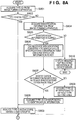
- Figs. 8A , 8B , 9A-1 , 9A-2 , 9B-1 and 9B-2 are flowcharts illustrating the processing procedure of the generic device driver installer operating on the client PC. Processing of customizing a generic device driver for controlling an image forming apparatus and installing it in a client PC 1 will be described with reference to Figs. 8A , 8B , 9A-1 , 9A-2 , 9B-1 and 9B-2B .
- Generic device driver installer is realized as an application program of installer on Operating System (OS) or a part of the OS.
- OS Operating System
- the user designates an image forming apparatus as a control target and activates the generic device driver installer stored in the HDD 208 using the function provided by the OS.
- the CPU 203 reads out the generic device driver installer, expands it on the main memory 212, and executes the program using the memory.
- step S801 the generic device driver installer searches for the image forming apparatus designated as the control target and acquires, from the image forming apparatus, a type ID generated in accordance with its functional arrangement.
- the control target is image forming apparatus A
- “type ID: AA” is acquired.
- the control target is image forming apparatus C
- “type ID: DD” is acquired.
- no type ID is acquired.
- the generic device driver acquires the type ID by communicating with the image forming apparatus via the network, USB I/F, or 1394 I/F.
- the type ID format and the acquisition method are not limited to those described above.
- step S802 the installer determines whether the type ID is acquired from the image forming apparatus.
- the control target is image forming apparatus A
- "type ID: AA” is acquired, and the process therefore advances to step S803.
- the installer analyzes the type ID and acquires "series ID: A” and "group ID: A” contained in the type ID.
- step S803 the installer acquires "series ID: D" and "group ID: D" contained in the type ID.
- the installer acquires identification information from the image forming apparatus.
- the installer acquires, as the identification information from image forming apparatus B, information representing that the control target is image forming apparatus B.
- step S805. The installer determines whether the identification information is acquired. If it is determined that no identification information is acquired because of, for example, a communication error, the process advances to step S810. The installer displays an error message representing that no device driver exists, and ends the processing.
- step S806 The installer causes the device specifications converter 502 to search the device specifications conversion table 503 using the identification information as a key in order to acquire the type ID of the image forming apparatus.
- step S807 the installer determines whether the identification information is registered in the device specifications conversion table 503. If the identification information is registered, the process advances to step S808 to acquire a type ID corresponding to the identification information.
- step S803 The installer analyzes the type ID and acquires a series ID and a group ID contained in the type ID.
- “type ID: BB” is registered in the device specifications conversion table 503 in correspondence with image forming apparatus B, as shown in Fig. 6 .
- “type ID: BB”, “series ID: B”, and “group ID: B” are acquired.
- step S807 If it is determined in step S807 that the identification information is not registered, the process advances to step S809.
- the installer acquires the default series ID and group ID by referring to the default type setting area 504 of its own. Note that when the user has designated the image forming apparatus as the control target, the port of the search target may have been designated. In that case, a series ID corresponding to the designated port may be adopted, and the default value may be obtained only for the group ID. In this embodiment, if the identification information is not registered, "series ID: C" and "group ID: C" are acquired as default values.
- step S811 To specify the generic device driver to be installed, the installer refers to the series ID storage area 506 of its own, thereby specifying the corresponding generic device driver in step S811. In step S812, the installer determines whether the generic device driver is specified. If the generic device driver cannot be specified, the process advances to step S817. The installer acquires the default series ID by referring to the default type setting area 504 of its own and returns the process to step S811. In this embodiment, when the control target is image forming apparatus C, the generic device driver cannot be specified in step S812. In this case, the installer acquires "C" as the default series ID.
- step S812 If the generic device driver is specified in step S812, the process advances to step S813.
- the installer stores the acquired group ID in the nonvolatile memory.
- step S814 the installer confirms using the function of the OS whether the generic device driver specified in step S812 has already been installed. If the generic device driver has not been installed, the process advances to step S815. The installer installs the specified generic device driver and advances the process to step S816.
- step S816 the installer initializes the generic device driver to customize it.
- generic device driver A is initialized.
- control target is image forming apparatus B
- generic device driver B is initialized.
- control target is image forming apparatus C
- generic device driver C is initialized.
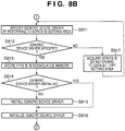
- Figs. 9A-1 and 9A-2 are flowcharts illustrating the processing procedure (following step S816) of the generic device driver installer operating on the client PC.
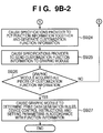
- step S901 the UI module of the generic device driver acquires the group ID by referring to the nonvolatile memory.
- the generic device driver requests the specifications provider 712 of its own to specify customization information using the group ID and notify.
- step S903 the specifications provider 712 searches the customization information storage area 713 using the group ID as a key to specify customization information corresponding to the specific group ID.
- step S904 it is determined whether the specifications provider 712 has specified customization information. If no customization information can be specified, the specifications provider 712 notifies, in step S908, the UI module that no customization information can be specified. In step S909, the UI module acquires the default group ID by referring to the default type setting area 504. Then, the process returns to step S902.
- step S904 when the control target is, for example, image forming apparatus C, no customization information can be specified in step S904. For this reason, the UI module acquires "C" as the default group ID and returns the process to step S902.
- step S905 If customization information is specified in step S904, the process advances to step S905.
- the specifications provider 712 notifies the UI module of the specified customization information.
- the specifications provider 712 acquires customization information including pieces of function information "driver UI type: type A”, “device control instruction set: type A”, “paper selecting function: type A”, “paper cassette selecting function: type A”, “color/monochrome print function: type A”, “resolution selecting function: type A”, “finisher selecting function: type A”, and "two-way communication function: type A” and notifies the UI module of it.
- step S906 the UI module stores the acquired customization information in the nonvolatile memory.
- step S907 the UI module extracts function information necessary for customization from the customization information.
- step S910 the UI module notifies the specifications provider 712 of the function information and requests to acquire UI-associated customization function information.
- step S911 the specifications provider 712 determines whether the function information that needs to be acquired is device independent function information. If the function information that needs to be acquired is device independent function information, the process advances to step S912. The specifications provider 712 searches the device independent function information storage area 714 and acquires the function information concerned.
- step S913 If the function information that needs to be acquired is not device independent function information, the process advances to step S913.
- the specifications provider 712 searches the device dependent function information storage area 720 and acquires the function information concerned.
- step S914 the specifications provider 712 generates customization function information by putting together the pieces of acquired function information.
- step S915 the specifications provider 712 notifies the UI module of the generated customization function information.
- the generic device driver A UI module 702 requests to acquire the function information of "driver unit type: type A” and the function information of "paper cassette selecting function: type A".
- the specifications provider 712 searches the device independent function information storage area 714 and acquires "template: UI template 1", "resource language: Japanese”, and "Bitmap type: type A" as the function information of "driver unit type: type A”.
- the specifications provider 712 also searches the device dependent function information storage area 720 and acquires "number of paper cassettes: 4" as the function information of "paper cassette selecting function: type A". The specifications provider 712 puts together the two pieces of acquired function information and sends them to the UI module as customization information.
- step S916 the UI module determines whether all pieces of customization function information have been acquired. If customization function information to acquire still remains, the process returns to step S910.
- the UI module requests the specifications provider 712 to acquire the next customization function information.
- the generic device driver A UI module 702 succeedingly requests to acquire the function information of "paper selecting function: type A", the function information of "resolution selecting function: type A”, and the function information of "finisher selecting function: type A”.
- the specifications provider 712 acquires the pieces of function information concerned and puts together and sends them to the UI module as customization information.
- step S916 If it is determined in step S916 that all pieces of customization function information have been acquired, the process advances to step S917.
- the UI module of the generic device driver customizes the UI screen and UI functions it will provide to the user in accordance with the acquired customization function information.
- step S918 the graphic module of the generic device driver acquires customization information by referring to the nonvolatile memory.
- step S919 the graphic module extracts function information necessary for customization from the customization information.
- step S920 the graphic module notifies the specifications provider 712 of the function information and requests to acquire necessary customization function information.
- step S921 the specifications provider 712 determines whether the function information that needs to be acquired is device independent function information. If the function information that needs to be acquired is device independent function information, the process advances to step S922. The specifications provider 712 searches the device independent function information storage area 714 and acquires the function information concerned.
- step S923 If the function information that needs to be acquired is not device independent function information, the process advances to step S923.
- the specifications provider 712 searches the device dependent function information storage area 720 and acquires the function information concerned.
- step S924 the specifications provider 712 generates customization function information by putting together the pieces of acquired function information.
- step S925 the specifications provider 712 notifies the graphic module of the generated customization function information.
- the generic device driver A graphic module 703 requests to acquire the function information of "device control instruction set: type A", the function information of "paper cassette selecting function: type A", the function information of "paper selecting function: type A”, the function information of "color/monochrome print function: type A”, the function information of "resolution selecting function: type A”, the function information of "finisher selecting function: type A", and the function information of "two-way communication function: type A”.
- the specifications provider 712 searches the device dependent function information storage area 720 and acquires, for example, "instruction set: A” and “PDL: LIPS1” as the function information of "device control instruction set: type A", "number of paper cassettes: 4" as the function information of "paper cassette selecting function: type A", "type: plain paper, thick paper, thin paper” and “size: A3, B4, A4, B5, A5, Legal, Letter” as the function information of "paper selecting function: type A”, “color print: available” and “monochrome print: available” as the function information of "color/monochrome print function: type A", "600 dpi: available” and “1200 dpi: available” as the function information of "resolution selecting function: type A", “stapling: available” and “case biding: available” as the function information of "finisher selecting function: type A", and "USB I/F communication: possible” and “TCP/IP communication: possible” as the function information of "two-way communication function: type A".
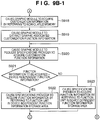
- step S926 the graphic module determines whether all pieces of customization function information have been acquired. If customization function information to acquire still remains, the process returns to step S920. The graphic module requests the specifications provider 712 to acquire the next customization function information.
- step S926 If it is determined in step S926 that all pieces of customization function information have been acquired, the process advances to step S927.
- the graphic module of the generic device driver determines print data generation rules, device control instructions to be used to control the image forming apparatus, and the setting parameter instructions of the device control instructions in accordance with the acquired customization function information. More specifically, the generic device driver has, for each image forming apparatus series, functional modules to implement functions providable by image forming apparatuses of a type belonging to the series.
- the device driver is reconfigured by selecting appropriate functional modules in accordance with the customization information decided by the above-described procedure.
- the reconfigured device driver is installed in the client computer.
- the apparatus arrangement and processing procedure of this embodiment obviate the need for developing and maintaining different device drivers for respective image forming apparatuses and lighten the burden on both the device driver provider and the device driver user.
- the functions of an image forming apparatus are transferred using a type ID with a small data amount. This makes it possible to acquire information necessary for customization from the image forming apparatus using an information transfer method capable of transferring only a small quantity of data.
- FIG. 10 is a block diagram showing an example of the arrangement of the FAX transmission system according to the second embodiment of the present invention.
- the network 1007 can have either one system or a plurality of systems.
- PCs 1001, 1002, and 1003 are client PCs.
- the network 1007 connects them.
- An image forming apparatus 1004 is image forming apparatus U.
- An image forming apparatus 1005 is image forming apparatus V.
- An image forming apparatus 1006 is image forming apparatus W.
- An image forming apparatus according to this embodiment is an MFP having at least a facsimile function or a facsimile apparatus having a single facsimile function. Each image forming apparatus has a function of receiving digital data from a client PC and FAX-transmitting it.
- the image forming apparatus U 1004 has the following functions and is designed to be controllable by a device control instruction set of type A.
- the image forming apparatus V 1005 has the following functions and is designed to be controllable by a device control instruction set of type A.
- the image forming apparatus W 1006 has the following functions and is designed to be controllable by a device control instruction set of type D.
- the device control instruction set of type D includes a device control instruction set of type C.
- the two-way communication function of type D includes a two-way communication function of type C.
- Figs. 11A and 11B are views showing the relationship between generic FAX drivers and image forming apparatuses according to the second embodiment of the present invention.
- an image forming apparatus 1105 is image forming apparatus U.
- An image forming apparatus 1106 is image forming apparatus N.
- An image forming apparatus 1108 is image forming apparatus V.
- An image forming apparatus 1109 is image forming apparatus M.
- An image forming apparatus 1111 is image forming apparatus W.
- An image forming apparatus series 1104 is image forming apparatus series U.
- An image forming apparatus series 1107 is image forming apparatus series V.
- An image forming apparatus series 1110 belongs to image forming apparatus series W.
- the image forming apparatus series U 1104 includes the image forming apparatuses U 1105 and N 1106.
- the image forming apparatus series V 1107 includes the image forming apparatuses V 1108 and M 1109.
- the image forming apparatus series W 1110 includes the image forming apparatus W 1111.
- a driver 1101 is generic FAX driver U.
- a driver 1102 is generic FAX driver V.
- a driver 1103 is generic FAX driver W.
- the generic FAX driver U 1101 is a FAX driver for the image forming apparatus series U 1104.
- the generic FAX driver U 1101 has a function of providing a driver UI screen of type A or D to the user, and a function of controlling an image forming apparatus by transmitting the device control instruction set of type A or B to it.
- the generic FAX driver V 1102 is a FAX driver for the image forming apparatuses belonging to the image forming apparatus series V 1107.
- the generic FAX driver V 1102 has a function of providing a driver UI screen of type A to the user, and a function of controlling an image forming apparatus by transmitting the device control instruction set of type A to it.
- the generic FAX driver W 1103 is a FAX driver for the image forming apparatus series W 1110.
- the generic FAX driver W 1103 has a function of providing a driver UI screen of type C to the user, and a function of controlling an image forming apparatus by transmitting the device control instruction set of type B to it.
- Each generic FAX driver has various kinds of functions conforming to the functions of a plurality of image forming apparatuses belonging to a corresponding image forming apparatus series, and a function of customizing itself in accordance with the functions of each image forming apparatus.
- the generic FAX driver U 1101 has the following functions.
- the generic FAX driver V 1102 has the following functions.
- the generic FAX driver W 1103 has the following functions.
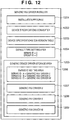
- Fig. 12 is a block diagram showing the arrangement of a generic FAX driver installer according to the second embodiment of the present invention.
- the generic FAX driver installer is stored in a hard disk drive (HDD) 208 of the client PC.
- a program 1201 is an installation program.
- a program 1202 is a device specifications converter.
- a program 1203 is a device specifications conversion table.
- a program 1204 is a default type setting area.
- a program 1205 is a generic device driver storage area.
- a series ID storage area 1206 stores, as information that associates a series ID with a generic FAX driver, generic FAX driver U for series ID: A, generic FAX driver V for series ID: B, and generic FAX driver W for series ID: C.
- reference numeral 1207 denotes generic FAX driver U; 1208, generic FAX driver V; and 1209, generic FAX driver W.
- Fig. 13 is a view showing an example of association information stored in the device specifications conversion table according to the second embodiment of the present invention.
- the device specifications conversion table stores "type ID: BB" associated with "identification information: image forming apparatus V".
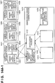
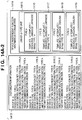
- Figs. 14A-1 , 14A-2 and 14B are views showing details of the generic FAX drivers stored in the generic device driver storage area according to the second embodiment of the present invention.
- the generic FAX drivers are packaged together in the generic FAX driver installer and stored in the hard disk drive (HDD) 208 of the client PC.
- HDD hard disk drive
- a unit 1401 is a generic FAX driver U dependent portion.
- a unit 1404 is a generic FAX driver V dependent portion.
- a unit 1407 is a generic FAX driver W dependent portion.
- a unit 1410 is a generic FAX driver common portion.
- a module 1402 is a generic FAX driver U UI module.
- a module 1403 is a generic FAX driver U graphic module.
- a module 1405 is a generic FAX driver V UI module.
- a module 1406 is a generic FAX driver V graphic module.
- a module 1408 is a generic FAX driver W UI module.
- a module 1409 is a generic FAX driver W graphic module.
- reference numeral 1411 denotes a nonvolatile memory; 1412, a specifications provider; 1413, a customization information storage area; 1414, a device independent function information storage area; 1415, a driver UI type unit; 1416, type A function information; 1417, type B function information; 1418, type C function information; and 1419, type D function information.
- a device dependent function information storage area 1420 stores device dependent function information.
- a device control instruction set unit 1421 stores information about the control instructions of the image forming apparatuses usable by the FAX drivers.
- the device control instruction set unit 1421 includes type A function information 1422 and type B function information 1423.
- the type A function information 1422 sets "instruction set: A". This information represents that it is necessary to use the instruction set A as a device control instruction.
- the type B function information 1423 sets "instruction set: B". This information represents that it is necessary to use the instruction set B as a device control instruction.
- a broadcast selecting function unit 1424 stores information about the broadcast functions usable by the FAX drivers.
- the broadcast selecting function unit 1424 includes type A function information 1425, type B function information 1426, and type C function information 1427.
- the type A function information 1425 sets "broadcast function: available" and "number of broadcast destinations: 50". This information represents that it is possible to set 50 broadcast destinations at maximum per FAX transmission.
- the type B function information 1426 sets "broadcast function: available" and "number of broadcast destinations: 10". This information represents that it is possible to set 10 broadcast destinations at maximum per FAX transmission.
- the type C function information 1427 sets "broadcast function: not available”. This information represents that there is no broadcast function.
- a resolution selecting function unit 1428 stores information about the resolutions of FAX-transmissible image data.
- the resolution selecting function unit 1428 includes type A function information 1429 and type B function information 1430.
- the type A function information 1429 sets "200 dpi: available” and "400 dpi: available”. This information represents that it is possible to FAX-transmit 200- or 400-dpi image data.
- the type B function information 1430 sets "200 dpi: available". This information represents that it is possible to FAX-transmit 200-dpi image data.
- a timer transmission selecting function unit 1431 stores information about the function of performing FAX transmission at a time designated by a timer transmission function unit.
- the timer transmission selecting function unit 1431 includes type A function information 1432 and type B function information 1433.
- the type A function information 1432 sets "timer transmission function: available". This information represents that it is possible to issue, to an image forming apparatus, a FAX transmission instruction containing a designated timer transmission time in accordance with a user instruction.
- the type B function information 1433 sets "timer transmission function: not available". This information represents that there is no timer transmission function.
- a two-way communication function unit 1434 stores information about the two-way communication functions usable by the FAX drivers.
- the two-way communication function unit 1434 includes type A function information 1435, type B function information 1436, and type C function information 1437.
- the type A function information 1435 sets "USB I/F communication: possible" and "TCP/IP communication: possible”. This information represents that the FAX driver can exchange information with an image forming apparatus by two-way communication using USB I/F and TCP/IP communications.
- the type B function information 1436 sets "TCP/IP communication: possible". This information represents that the FAX driver can exchange information with an image forming apparatus by two-way communication using TCP/IP communication.
- the type C function information 1437 sets "1394 I/F communication: possible". This information represents that the FAX driver can exchange information with an image forming apparatus by two-way communication using 1394 I/F communication.
- the processing procedure of the generic FAX driver installer according to the second embodiment of the present invention is the same as that of the generic device driver installer described in the first embodiment of the present invention, and a description thereof will not be repeated.
- the device is not a printer but a facsimile, it is possible to install an appropriate device driver according to the model (type) of the device, as in the first embodiment.
- aspects of the present invention can also be realized by a computer of a system or apparatus (or devices such as a CPU or MPU) that reads out and executes a program recorded on a memory device to perform the functions of the above-described embodiments, and by a method, the steps of which are performed by a computer of a system or apparatus by, for example, reading out and executing a program recorded on a memory device to perform the functions of the above-described embodiments.
- the program is provided to the computer for example via a network or from a recording medium of various types serving as the memory device (e.g., computer-readable medium).
- the system or apparatus, and the recording medium where the program is stored are included as being within the scope of the present invention.
- This invention lightens a burden in development by using a generic device driver and also lightens a burden on a user by automatically performing customization suitable for a model to be installed.
Landscapes
- Engineering & Computer Science (AREA)
- Theoretical Computer Science (AREA)
- Human Computer Interaction (AREA)
- Physics & Mathematics (AREA)
- General Engineering & Computer Science (AREA)
- General Physics & Mathematics (AREA)
- Accessory Devices And Overall Control Thereof (AREA)
- Stored Programmes (AREA)
Applications Claiming Priority (1)
| Application Number | Priority Date | Filing Date | Title |
|---|---|---|---|
| JP2008255247A JP5264391B2 (ja) | 2008-09-30 | 2008-09-30 | 情報処理装置及びインストール方法 |
Publications (3)
| Publication Number | Publication Date |
|---|---|
| EP2169531A2 EP2169531A2 (en) | 2010-03-31 |
| EP2169531A3 EP2169531A3 (en) | 2011-12-28 |
| EP2169531B1 true EP2169531B1 (en) | 2019-05-01 |
Family
ID=41181046
Family Applications (1)
| Application Number | Title | Priority Date | Filing Date |
|---|---|---|---|
| EP09169341.6A Active EP2169531B1 (en) | 2008-09-30 | 2009-09-03 | Device driver installer and installation method |
Country Status (4)
| Country | Link |
|---|---|
| US (1) | US8448191B2 (cg-RX-API-DMAC7.html) |
| EP (1) | EP2169531B1 (cg-RX-API-DMAC7.html) |
| JP (1) | JP5264391B2 (cg-RX-API-DMAC7.html) |
| CN (1) | CN101714125B (cg-RX-API-DMAC7.html) |
Families Citing this family (12)
| Publication number | Priority date | Publication date | Assignee | Title |
|---|---|---|---|---|
| JP5528196B2 (ja) * | 2010-05-06 | 2014-06-25 | キヤノン株式会社 | 印刷制御装置、印刷制御方法およびプログラム |
| US8773674B2 (en) * | 2010-09-17 | 2014-07-08 | Xerox Corporation | Method and apparatus to provide enhanced printing for newly launched devices in a universal printer driver |
| JP5754123B2 (ja) * | 2010-12-10 | 2015-07-29 | 株式会社リコー | 情報処理装置 |
| CN102023882A (zh) * | 2010-12-22 | 2011-04-20 | 福建天晴在线互动科技有限公司 | 计算机自动识别手机并安装手机驱动程序的系统及方法 |
| JP6035704B2 (ja) * | 2011-03-18 | 2016-11-30 | セイコーエプソン株式会社 | 周辺装置、管理装置及び機種情報送信方法 |
| EP2705428A4 (en) * | 2011-05-04 | 2014-10-15 | Apperian Inc | PROCESSING, MODIFICATION AND DISTRIBUTION OF INSTALLATION PACKAGES |
| JP5174268B1 (ja) * | 2011-10-14 | 2013-04-03 | キヤノン株式会社 | ネットワークシステム及びクライアント装置とその方法 |
| JP5835486B2 (ja) * | 2012-07-19 | 2015-12-24 | 日本電気株式会社 | 情報処理システムのデバイス初期設定カスタマイズ方法 |
| CN104850413A (zh) * | 2014-02-13 | 2015-08-19 | 中兴通讯股份有限公司 | 数据终端主机软件安装方法及装置 |
| CN103995714B (zh) * | 2014-04-29 | 2017-10-24 | 珠海赛纳打印科技股份有限公司 | 设备驱动程序安装方法及设备 |
| JP6983614B2 (ja) * | 2017-10-16 | 2021-12-17 | キヤノン株式会社 | プログラム |
| CN108459552B (zh) * | 2018-01-31 | 2021-07-23 | 南京拓控信息科技股份有限公司 | 一种智能化面向对象的可编程的自动化控制方法 |
Citations (1)
| Publication number | Priority date | Publication date | Assignee | Title |
|---|---|---|---|---|
| EP1586989A2 (en) * | 2004-04-12 | 2005-10-19 | Ricoh Company, Ltd. | Automatic customization of printer drivers |
Family Cites Families (16)
| Publication number | Priority date | Publication date | Assignee | Title |
|---|---|---|---|---|
| JPH10340168A (ja) * | 1997-06-06 | 1998-12-22 | Canon Inc | 情報処理装置および情報処理システムおよびそれらの制御方法 |
| US6952831B1 (en) * | 1999-02-26 | 2005-10-04 | Microsoft Corporation | Driverless printing |
| US7047534B2 (en) * | 2000-03-17 | 2006-05-16 | Microsoft Corporation | Simplified device drivers for hardware devices of a computer system |
| JP2002041257A (ja) * | 2000-07-24 | 2002-02-08 | Minolta Co Ltd | プリンタドライバのインストール方法、プリンタドライバ用インストールプログラムを記録した記録媒体、およびプリンタドライバ用インストール装置 |
| US7574713B2 (en) * | 2001-11-05 | 2009-08-11 | Trendium, Inc. | Methods, systems, and computer program products for instantiating a device driver for communication with a device by dynamically associating the device driver at run-time with a device-specific and/or service-specific software component |
| US20030196007A1 (en) * | 2002-04-12 | 2003-10-16 | Baron John M. | Device-resident driver system and method |
| JP2004151816A (ja) * | 2002-10-29 | 2004-05-27 | Konica Minolta Holdings Inc | ホスト装置 |
| US7853946B2 (en) * | 2003-02-28 | 2010-12-14 | Canon Kabushiki Kaisha | Information processing apparatus, information processing method, and control program |
| JP4371673B2 (ja) * | 2003-02-28 | 2009-11-25 | キヤノン株式会社 | プログラムインストール方法およびサーバ装置 |
| US20050039193A1 (en) * | 2003-03-20 | 2005-02-17 | Samsung Electronics Co., Ltd. | Method and apparatus for generating device driver and user interface screen |
| US7949733B2 (en) * | 2004-02-02 | 2011-05-24 | Fuji Xerox Co., Ltd. | Driver management method, driver management apparatus, and driver management program |
| JP4623461B2 (ja) * | 2004-11-30 | 2011-02-02 | キヤノンマーケティングジャパン株式会社 | 情報処理装置および印刷制御方法およびプリンタドライバプログラムおよび記録媒体 |
| JP2006236242A (ja) * | 2005-02-28 | 2006-09-07 | Canon Inc | デバイス識別処理方法 |
| JP4599206B2 (ja) * | 2005-03-29 | 2010-12-15 | キヤノン株式会社 | 情報処理装置及び情報処理装置の制御方法、プログラム、記憶媒体 |
| JP2007264864A (ja) * | 2006-03-28 | 2007-10-11 | Brother Ind Ltd | インストールプログラム |
| JP4805116B2 (ja) * | 2006-12-11 | 2011-11-02 | 株式会社日立製作所 | 情報処理システム、情報処理システムの制御方法、サービス利用装置及びサービス提供装置 |
-
2008
- 2008-09-30 JP JP2008255247A patent/JP5264391B2/ja active Active
-
2009
- 2009-09-01 US US12/551,811 patent/US8448191B2/en active Active
- 2009-09-03 EP EP09169341.6A patent/EP2169531B1/en active Active
- 2009-09-30 CN CN2009101774850A patent/CN101714125B/zh active Active
Patent Citations (1)
| Publication number | Priority date | Publication date | Assignee | Title |
|---|---|---|---|---|
| EP1586989A2 (en) * | 2004-04-12 | 2005-10-19 | Ricoh Company, Ltd. | Automatic customization of printer drivers |
Also Published As
| Publication number | Publication date |
|---|---|
| US8448191B2 (en) | 2013-05-21 |
| JP2010086313A (ja) | 2010-04-15 |
| EP2169531A3 (en) | 2011-12-28 |
| EP2169531A2 (en) | 2010-03-31 |
| CN101714125A (zh) | 2010-05-26 |
| CN101714125B (zh) | 2012-07-04 |
| US20100083284A1 (en) | 2010-04-01 |
| JP5264391B2 (ja) | 2013-08-14 |
Similar Documents
| Publication | Publication Date | Title |
|---|---|---|
| EP2169531B1 (en) | Device driver installer and installation method | |
| JP7791270B2 (ja) | 印刷処理システム、および制御方法 | |
| US7852497B2 (en) | Method of controlling printing control apparatus | |
| EP2284696B1 (en) | File printing by means of drag-and-drop | |
| KR101101101B1 (ko) | 정보 처리 장치 및 정보 처리 방법 | |
| CN103309630B (zh) | 信息处理装置及信息处理方法 | |
| US9442678B2 (en) | Information processing apparatus, information processing system and non-transitory computer-readable information recording medium | |
| EP1293886A2 (en) | Controlling printing by use of a virtual printer | |
| US20080068655A1 (en) | Data processing apparatus and recording medium | |
| EP1835395A2 (en) | Information processing apparatus, control method therefor, and program | |
| JP7487277B2 (ja) | プログラム、情報処理装置、及び情報処理装置の制御方法 | |
| JP5538916B2 (ja) | 情報処理装置、情報処理方法及びプログラム | |
| US8451484B2 (en) | Information processing apparatus, printing apparatus, electronic device, and computer program therefor based on existence of printer configuration file | |
| EP2230630B1 (en) | Printer, and program for its operation screen. | |
| US20110302575A1 (en) | Print control apparatus and display method for the same | |
| JP5879807B2 (ja) | 印刷制御装置、制御プログラム及び記録媒体 | |
| JP2001159959A (ja) | 周辺機器制御方法および装置および記録媒体 | |
| EP1662371B1 (en) | Method of protecting leakage of information, and information processing apparatus and driver program which implement the method | |
| JP4467855B2 (ja) | 情報処理装置、情報処理方法及びプログラム | |
| JP7242203B2 (ja) | 情報処理装置、アプリケーションおよび制御方法 | |
| JP7746895B2 (ja) | サポートプログラム | |
| JP2006228128A (ja) | 情報処理装置、通信機器制御装置およびプログラム | |
| JP7085920B2 (ja) | 印刷制御プログラム、情報処理装置とその制御方法、およびプログラム | |
| JP2007140952A (ja) | 分散処理システム及びその処理方法 | |
| Both | Printing |
Legal Events
| Date | Code | Title | Description |
|---|---|---|---|
| PUAI | Public reference made under article 153(3) epc to a published international application that has entered the european phase |
Free format text: ORIGINAL CODE: 0009012 |
|
| AK | Designated contracting states |
Kind code of ref document: A2 Designated state(s): AT BE BG CH CY CZ DE DK EE ES FI FR GB GR HR HU IE IS IT LI LT LU LV MC MK MT NL NO PL PT RO SE SI SK SM TR |
|
| AX | Request for extension of the european patent |
Extension state: AL BA RS |
|
| PUAL | Search report despatched |
Free format text: ORIGINAL CODE: 0009013 |
|
| AK | Designated contracting states |
Kind code of ref document: A3 Designated state(s): AT BE BG CH CY CZ DE DK EE ES FI FR GB GR HR HU IE IS IT LI LT LU LV MC MK MT NL NO PL PT RO SE SI SK SM TR |
|
| AX | Request for extension of the european patent |
Extension state: AL BA RS |
|
| RIC1 | Information provided on ipc code assigned before grant |
Ipc: G06F 3/12 20060101AFI20111121BHEP |
|
| 17P | Request for examination filed |
Effective date: 20120628 |
|
| STAA | Information on the status of an ep patent application or granted ep patent |
Free format text: STATUS: EXAMINATION IS IN PROGRESS |
|
| 17Q | First examination report despatched |
Effective date: 20170706 |
|
| GRAP | Despatch of communication of intention to grant a patent |
Free format text: ORIGINAL CODE: EPIDOSNIGR1 |
|
| STAA | Information on the status of an ep patent application or granted ep patent |
Free format text: STATUS: GRANT OF PATENT IS INTENDED |
|
| INTG | Intention to grant announced |
Effective date: 20181119 |
|
| GRAS | Grant fee paid |
Free format text: ORIGINAL CODE: EPIDOSNIGR3 |
|
| GRAA | (expected) grant |
Free format text: ORIGINAL CODE: 0009210 |
|
| STAA | Information on the status of an ep patent application or granted ep patent |
Free format text: STATUS: THE PATENT HAS BEEN GRANTED |
|
| AK | Designated contracting states |
Kind code of ref document: B1 Designated state(s): AT BE BG CH CY CZ DE DK EE ES FI FR GB GR HR HU IE IS IT LI LT LU LV MC MK MT NL NO PL PT RO SE SI SK SM TR |
|
| REG | Reference to a national code |
Ref country code: GB Ref legal event code: FG4D |
|
| REG | Reference to a national code |
Ref country code: CH Ref legal event code: EP Ref country code: AT Ref legal event code: REF Ref document number: 1127811 Country of ref document: AT Kind code of ref document: T Effective date: 20190515 |
|
| REG | Reference to a national code |
Ref country code: DE Ref legal event code: R096 Ref document number: 602009058091 Country of ref document: DE |
|
| REG | Reference to a national code |
Ref country code: IE Ref legal event code: FG4D |
|
| REG | Reference to a national code |
Ref country code: NL Ref legal event code: MP Effective date: 20190501 |
|
| REG | Reference to a national code |
Ref country code: LT Ref legal event code: MG4D |
|
| PG25 | Lapsed in a contracting state [announced via postgrant information from national office to epo] |
Ref country code: NL Free format text: LAPSE BECAUSE OF FAILURE TO SUBMIT A TRANSLATION OF THE DESCRIPTION OR TO PAY THE FEE WITHIN THE PRESCRIBED TIME-LIMIT Effective date: 20190501 Ref country code: ES Free format text: LAPSE BECAUSE OF FAILURE TO SUBMIT A TRANSLATION OF THE DESCRIPTION OR TO PAY THE FEE WITHIN THE PRESCRIBED TIME-LIMIT Effective date: 20190501 Ref country code: LT Free format text: LAPSE BECAUSE OF FAILURE TO SUBMIT A TRANSLATION OF THE DESCRIPTION OR TO PAY THE FEE WITHIN THE PRESCRIBED TIME-LIMIT Effective date: 20190501 Ref country code: HR Free format text: LAPSE BECAUSE OF FAILURE TO SUBMIT A TRANSLATION OF THE DESCRIPTION OR TO PAY THE FEE WITHIN THE PRESCRIBED TIME-LIMIT Effective date: 20190501 Ref country code: NO Free format text: LAPSE BECAUSE OF FAILURE TO SUBMIT A TRANSLATION OF THE DESCRIPTION OR TO PAY THE FEE WITHIN THE PRESCRIBED TIME-LIMIT Effective date: 20190801 Ref country code: SE Free format text: LAPSE BECAUSE OF FAILURE TO SUBMIT A TRANSLATION OF THE DESCRIPTION OR TO PAY THE FEE WITHIN THE PRESCRIBED TIME-LIMIT Effective date: 20190501 Ref country code: PT Free format text: LAPSE BECAUSE OF FAILURE TO SUBMIT A TRANSLATION OF THE DESCRIPTION OR TO PAY THE FEE WITHIN THE PRESCRIBED TIME-LIMIT Effective date: 20190901 Ref country code: FI Free format text: LAPSE BECAUSE OF FAILURE TO SUBMIT A TRANSLATION OF THE DESCRIPTION OR TO PAY THE FEE WITHIN THE PRESCRIBED TIME-LIMIT Effective date: 20190501 |
|
| PG25 | Lapsed in a contracting state [announced via postgrant information from national office to epo] |
Ref country code: LV Free format text: LAPSE BECAUSE OF FAILURE TO SUBMIT A TRANSLATION OF THE DESCRIPTION OR TO PAY THE FEE WITHIN THE PRESCRIBED TIME-LIMIT Effective date: 20190501 Ref country code: GR Free format text: LAPSE BECAUSE OF FAILURE TO SUBMIT A TRANSLATION OF THE DESCRIPTION OR TO PAY THE FEE WITHIN THE PRESCRIBED TIME-LIMIT Effective date: 20190802 Ref country code: BG Free format text: LAPSE BECAUSE OF FAILURE TO SUBMIT A TRANSLATION OF THE DESCRIPTION OR TO PAY THE FEE WITHIN THE PRESCRIBED TIME-LIMIT Effective date: 20190801 |
|
| REG | Reference to a national code |
Ref country code: AT Ref legal event code: MK05 Ref document number: 1127811 Country of ref document: AT Kind code of ref document: T Effective date: 20190501 |
|
| PG25 | Lapsed in a contracting state [announced via postgrant information from national office to epo] |
Ref country code: IS Free format text: LAPSE BECAUSE OF FAILURE TO SUBMIT A TRANSLATION OF THE DESCRIPTION OR TO PAY THE FEE WITHIN THE PRESCRIBED TIME-LIMIT Effective date: 20190901 |
|
| PG25 | Lapsed in a contracting state [announced via postgrant information from national office to epo] |
Ref country code: CZ Free format text: LAPSE BECAUSE OF FAILURE TO SUBMIT A TRANSLATION OF THE DESCRIPTION OR TO PAY THE FEE WITHIN THE PRESCRIBED TIME-LIMIT Effective date: 20190501 Ref country code: SK Free format text: LAPSE BECAUSE OF FAILURE TO SUBMIT A TRANSLATION OF THE DESCRIPTION OR TO PAY THE FEE WITHIN THE PRESCRIBED TIME-LIMIT Effective date: 20190501 Ref country code: RO Free format text: LAPSE BECAUSE OF FAILURE TO SUBMIT A TRANSLATION OF THE DESCRIPTION OR TO PAY THE FEE WITHIN THE PRESCRIBED TIME-LIMIT Effective date: 20190501 Ref country code: AT Free format text: LAPSE BECAUSE OF FAILURE TO SUBMIT A TRANSLATION OF THE DESCRIPTION OR TO PAY THE FEE WITHIN THE PRESCRIBED TIME-LIMIT Effective date: 20190501 Ref country code: DK Free format text: LAPSE BECAUSE OF FAILURE TO SUBMIT A TRANSLATION OF THE DESCRIPTION OR TO PAY THE FEE WITHIN THE PRESCRIBED TIME-LIMIT Effective date: 20190501 Ref country code: EE Free format text: LAPSE BECAUSE OF FAILURE TO SUBMIT A TRANSLATION OF THE DESCRIPTION OR TO PAY THE FEE WITHIN THE PRESCRIBED TIME-LIMIT Effective date: 20190501 |
|
| REG | Reference to a national code |
Ref country code: DE Ref legal event code: R097 Ref document number: 602009058091 Country of ref document: DE |
|
| PG25 | Lapsed in a contracting state [announced via postgrant information from national office to epo] |
Ref country code: SM Free format text: LAPSE BECAUSE OF FAILURE TO SUBMIT A TRANSLATION OF THE DESCRIPTION OR TO PAY THE FEE WITHIN THE PRESCRIBED TIME-LIMIT Effective date: 20190501 Ref country code: IT Free format text: LAPSE BECAUSE OF FAILURE TO SUBMIT A TRANSLATION OF THE DESCRIPTION OR TO PAY THE FEE WITHIN THE PRESCRIBED TIME-LIMIT Effective date: 20190501 |
|
| PLBE | No opposition filed within time limit |
Free format text: ORIGINAL CODE: 0009261 |
|
| STAA | Information on the status of an ep patent application or granted ep patent |
Free format text: STATUS: NO OPPOSITION FILED WITHIN TIME LIMIT |
|
| PG25 | Lapsed in a contracting state [announced via postgrant information from national office to epo] |
Ref country code: TR Free format text: LAPSE BECAUSE OF FAILURE TO SUBMIT A TRANSLATION OF THE DESCRIPTION OR TO PAY THE FEE WITHIN THE PRESCRIBED TIME-LIMIT Effective date: 20190501 |
|
| 26N | No opposition filed |
Effective date: 20200204 |
|
| PG25 | Lapsed in a contracting state [announced via postgrant information from national office to epo] |
Ref country code: PL Free format text: LAPSE BECAUSE OF FAILURE TO SUBMIT A TRANSLATION OF THE DESCRIPTION OR TO PAY THE FEE WITHIN THE PRESCRIBED TIME-LIMIT Effective date: 20190501 |
|
| PG25 | Lapsed in a contracting state [announced via postgrant information from national office to epo] |
Ref country code: MC Free format text: LAPSE BECAUSE OF FAILURE TO SUBMIT A TRANSLATION OF THE DESCRIPTION OR TO PAY THE FEE WITHIN THE PRESCRIBED TIME-LIMIT Effective date: 20190501 Ref country code: SI Free format text: LAPSE BECAUSE OF FAILURE TO SUBMIT A TRANSLATION OF THE DESCRIPTION OR TO PAY THE FEE WITHIN THE PRESCRIBED TIME-LIMIT Effective date: 20190501 |
|
| REG | Reference to a national code |
Ref country code: CH Ref legal event code: PL |
|
| PG25 | Lapsed in a contracting state [announced via postgrant information from national office to epo] |
Ref country code: IE Free format text: LAPSE BECAUSE OF NON-PAYMENT OF DUE FEES Effective date: 20190903 Ref country code: LU Free format text: LAPSE BECAUSE OF NON-PAYMENT OF DUE FEES Effective date: 20190903 Ref country code: CH Free format text: LAPSE BECAUSE OF NON-PAYMENT OF DUE FEES Effective date: 20190930 Ref country code: LI Free format text: LAPSE BECAUSE OF NON-PAYMENT OF DUE FEES Effective date: 20190930 |
|
| REG | Reference to a national code |
Ref country code: BE Ref legal event code: MM Effective date: 20190930 |
|
| PG25 | Lapsed in a contracting state [announced via postgrant information from national office to epo] |
Ref country code: BE Free format text: LAPSE BECAUSE OF NON-PAYMENT OF DUE FEES Effective date: 20190930 |
|
| GBPC | Gb: european patent ceased through non-payment of renewal fee |
Effective date: 20190903 |
|
| PG25 | Lapsed in a contracting state [announced via postgrant information from national office to epo] |
Ref country code: GB Free format text: LAPSE BECAUSE OF NON-PAYMENT OF DUE FEES Effective date: 20190903 Ref country code: FR Free format text: LAPSE BECAUSE OF NON-PAYMENT OF DUE FEES Effective date: 20190930 |
|
| PG25 | Lapsed in a contracting state [announced via postgrant information from national office to epo] |
Ref country code: CY Free format text: LAPSE BECAUSE OF FAILURE TO SUBMIT A TRANSLATION OF THE DESCRIPTION OR TO PAY THE FEE WITHIN THE PRESCRIBED TIME-LIMIT Effective date: 20190501 |
|
| PG25 | Lapsed in a contracting state [announced via postgrant information from national office to epo] |
Ref country code: MT Free format text: LAPSE BECAUSE OF FAILURE TO SUBMIT A TRANSLATION OF THE DESCRIPTION OR TO PAY THE FEE WITHIN THE PRESCRIBED TIME-LIMIT Effective date: 20190501 Ref country code: HU Free format text: LAPSE BECAUSE OF FAILURE TO SUBMIT A TRANSLATION OF THE DESCRIPTION OR TO PAY THE FEE WITHIN THE PRESCRIBED TIME-LIMIT; INVALID AB INITIO Effective date: 20090903 |
|
| PG25 | Lapsed in a contracting state [announced via postgrant information from national office to epo] |
Ref country code: MK Free format text: LAPSE BECAUSE OF FAILURE TO SUBMIT A TRANSLATION OF THE DESCRIPTION OR TO PAY THE FEE WITHIN THE PRESCRIBED TIME-LIMIT Effective date: 20190501 |
|
| PGFP | Annual fee paid to national office [announced via postgrant information from national office to epo] |
Ref country code: DE Payment date: 20250820 Year of fee payment: 17 |