EP2169452A1 - Display device - Google Patents
Display device Download PDFInfo
- Publication number
- EP2169452A1 EP2169452A1 EP09012212A EP09012212A EP2169452A1 EP 2169452 A1 EP2169452 A1 EP 2169452A1 EP 09012212 A EP09012212 A EP 09012212A EP 09012212 A EP09012212 A EP 09012212A EP 2169452 A1 EP2169452 A1 EP 2169452A1
- Authority
- EP
- European Patent Office
- Prior art keywords
- image display
- heat
- flow path
- display panel
- ventilation
- Prior art date
- Legal status (The legal status is an assumption and is not a legal conclusion. Google has not performed a legal analysis and makes no representation as to the accuracy of the status listed.)
- Withdrawn
Links
Images


Classifications
-
- H—ELECTRICITY
- H05—ELECTRIC TECHNIQUES NOT OTHERWISE PROVIDED FOR
- H05K—PRINTED CIRCUITS; CASINGS OR CONSTRUCTIONAL DETAILS OF ELECTRIC APPARATUS; MANUFACTURE OF ASSEMBLAGES OF ELECTRICAL COMPONENTS
- H05K7/00—Constructional details common to different types of electric apparatus
- H05K7/20—Modifications to facilitate cooling, ventilating, or heating
- H05K7/20954—Modifications to facilitate cooling, ventilating, or heating for display panels
- H05K7/20972—Forced ventilation, e.g. on heat dissipaters coupled to components
-
- G—PHYSICS
- G02—OPTICS
- G02F—OPTICAL DEVICES OR ARRANGEMENTS FOR THE CONTROL OF LIGHT BY MODIFICATION OF THE OPTICAL PROPERTIES OF THE MEDIA OF THE ELEMENTS INVOLVED THEREIN; NON-LINEAR OPTICS; FREQUENCY-CHANGING OF LIGHT; OPTICAL LOGIC ELEMENTS; OPTICAL ANALOGUE/DIGITAL CONVERTERS
- G02F1/00—Devices or arrangements for the control of the intensity, colour, phase, polarisation or direction of light arriving from an independent light source, e.g. switching, gating or modulating; Non-linear optics
- G02F1/01—Devices or arrangements for the control of the intensity, colour, phase, polarisation or direction of light arriving from an independent light source, e.g. switching, gating or modulating; Non-linear optics for the control of the intensity, phase, polarisation or colour
- G02F1/13—Devices or arrangements for the control of the intensity, colour, phase, polarisation or direction of light arriving from an independent light source, e.g. switching, gating or modulating; Non-linear optics for the control of the intensity, phase, polarisation or colour based on liquid crystals, e.g. single liquid crystal display cells
- G02F1/133—Constructional arrangements; Operation of liquid crystal cells; Circuit arrangements
- G02F1/1333—Constructional arrangements; Manufacturing methods
- G02F1/133382—Heating or cooling of liquid crystal cells other than for activation, e.g. circuits or arrangements for temperature control, stabilisation or uniform distribution over the cell
- G02F1/133385—Heating or cooling of liquid crystal cells other than for activation, e.g. circuits or arrangements for temperature control, stabilisation or uniform distribution over the cell with cooling means, e.g. fans
-
- G—PHYSICS
- G09—EDUCATION; CRYPTOGRAPHY; DISPLAY; ADVERTISING; SEALS
- G09F—DISPLAYING; ADVERTISING; SIGNS; LABELS OR NAME-PLATES; SEALS
- G09F9/00—Indicating arrangements for variable information in which the information is built-up on a support by selection or combination of individual elements
- G09F9/30—Indicating arrangements for variable information in which the information is built-up on a support by selection or combination of individual elements in which the desired character or characters are formed by combining individual elements
- G09F9/35—Indicating arrangements for variable information in which the information is built-up on a support by selection or combination of individual elements in which the desired character or characters are formed by combining individual elements being liquid crystals
-
- G—PHYSICS
- G02—OPTICS
- G02F—OPTICAL DEVICES OR ARRANGEMENTS FOR THE CONTROL OF LIGHT BY MODIFICATION OF THE OPTICAL PROPERTIES OF THE MEDIA OF THE ELEMENTS INVOLVED THEREIN; NON-LINEAR OPTICS; FREQUENCY-CHANGING OF LIGHT; OPTICAL LOGIC ELEMENTS; OPTICAL ANALOGUE/DIGITAL CONVERTERS
- G02F2201/00—Constructional arrangements not provided for in groups G02F1/00 - G02F7/00
- G02F2201/36—Airflow channels, e.g. constructional arrangements facilitating the flow of air
Definitions
- the present invention relates to display devices, and particularly to a display device for outside installation.
- liquid crystal display is permanently installed outdoors.
- the reason includes the fact that the liquid crystal display has a small thickness and that the resolution of the image is high.
- the small thickness allows the installation of the display on the outer wall of the building or in narrow places such as a bus stop.
- the high resolution allows an image to be displayed clearly even if the display screen is small.
- the blackout is a phenomenon in which the temperature of the image display panel rises due to the heat generated from an image display panel in operation or the sun light, and an original function of the liquid crystal falls to disable the image display.
- a first display device comprises a display part, an accommodating part accommodating the display part, circulating means for circulating air in the accommodating part around the display part, and a heat exchanger arranged on a rear surface side of or below the display part.
- the circulating means includes a fan arranged adjacent to the heat exchanger, and the fan sends air toward the heat exchanger.
- a second display device is the first display device, wherein the heat exchanger includes an evaporator arranged on the rear side of the display part and adjacent to a lower end surface of the display part, and the fan is arranged above the evaporator.
- a third display device is the second display device, wherein the circulating means includes a second fan arranged adjacent to an upper end surface of the display part.
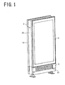
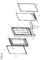
- An image display system has a flat rectangular solid-shaped appearance as shown in FIG. 1 , and comprises an image display device 1, a base 2, a backboard 3, a cover 4, a lighting apparatus 5 and a ventilation plate 6 as shown in FIG. 2 .
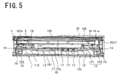
- the image display device 1 is a device displaying a video on a front surface 101 of the image display system, and includes a liquid crystal display 10 as shown in FIG. 5 . More details of the image display device 1 are described in "2. IMAGE DISPLAY DEVICE”.
- a frame member 21 for attaching the image display device 1 and the backboard 3 On the base 2, formed is a frame member 21 for attaching the image display device 1 and the backboard 3, and the frame member 21 has a structure in which the image display device 1 and the backboard 3 can be fitted therein.
- the backboard 3 is an installation base for affixing an advertising material, and is placed in the frame member 21 on a rear surface side of the image display device 1.
- the advertising material is affixed to a front surface 31 of the backboard 3, namely a surface facing a rear surface 102 side of the image display system.
- the backboard 3 is formed of a light transmitting material in order to transmit light emitted from the lighting apparatus 5.
- the advertising material affixed to the backboard 3 is formed of a light transmitting material in order to transmit the light emitted from the lighting apparatus 5.
- the advertising material formed of the light transmitting material is hereinafter referred to as an advertising film.
- the cover 4 is attached to the base 2, and covers the front surface 31 of the backboard 3 to which the advertising material is affixed. The advertising material is thereby protected by the cover 4.
- a part of the cover 4 opposed to the front surface 31 of the backboard 3 is formed of a light transmitting material. It is thus possible to view the advertising material from the rear surface 102 side of the image display system.
- the lighting apparatus 5 is an apparatus for illuminating the advertising film affixed to the front surface 31 of the backboard 3, and comprises a plurality of fluorescent lamps extending in a generally vertical direction.
- the lighting apparatus 5 is attached to the frame member 21 of the base 2 at a position between the image display device 1 and the backboard 3. Details of arrangement of the lighting apparatus 5 are described in "3. ARRANGEMENT OF LIGHTING APPARATUS".
- the ventilation plate 6 is arranged on each of the front surface 101 and the rear surface 102 of the image display system at a position below the image display device 1.
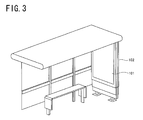
- the image display system described above is placed at a bus stop, for example, as shown in FIG. 3 .
- the image display system is placed so that the front surface 101 faces the inside of the bus stop and the rear surface 102 faces the outside of the bus stop.
- the front surface 101 of the image display system faces the inside of the bus stop according to the installed condition of the image display system described above, it is hard for a driver of a car or the like passing near the bus stop to see the front surface 101. Therefore, even when a moving image is displayed on the front surface 101, the attention of the driver is hard to be attracted to the moving image.
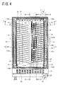
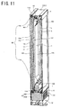
- the image display device 1 includes the liquid crystal display 10, a housing 12, a plurality of heat pipes 13, circulation fans 18, heat releasing fins 14, ventilation fans 15, 16 and a heat collecting fins 17 as shown in FIGS. 4 and 5 . As shown in FIG. 11 , the image display device 1 further includes an air conditioning machine 19, circulation fans 181 and a heat insulation member 7.
- the liquid crystal display 10 is a flat-panel display, and includes an image display panel 11 and a circuit board 11e for controlling the image display panel 11 as shown in FIG. 5 .
- the image display panel 11 is arranged inside an accommodation room 121 to be discussed later, while the circuit board 11e is arranged on an outer surface of a rear surface wall 125 forming the accommodation room 121.
- the image display panel 11 may take various shapes depending on the intended use.
- the image display panel 11 takes a lengthwise rectangular shape so that the image display system can be installed in a narrow place such as a bus stop.
- a part of the image display panel 11 adjacent to a display screen 112 in particular is easy to generate heat and be heated to a high temperature.
- the housing 12 has a waterproof structure, and is provided with the accommodation room 121 formed therein as shown in FIG. 4 .
- the image display panel 11 is arranged inside the accommodation room 121 with the display screen 112 facing the front surface 101 of the image display system as shown in FIG. 12 .
- the housing 12 includes a front surface wall 124 located on the display screen 112 side of the image display panel 11, a rear surface wall 125 located on a rear surface 111 side of the image display panel 11, and side surface walls 121a, 121b located on the opposite sides of the image display panel 11.
- the frame member 21 of the base 2 has an upper end part located on an upper end surface 113 side of the image display panel 11 and a lower end part located on a lower end surface 114 side of the image display panel 11.
- the accommodation room 121 is formed by the front surface wall 124, the rear surface wall 125, the side surface walls 121a, 121b, and the upper end part and the lower end part of the frame member 21, and is maintained in a sealed or substantially sealed state.
- the image display panel 11 By arranging the image display panel 11 inside the accommodation room 121 maintained in the sealed or substantially sealed state, it is possible to protect the image display panel 11 from weather and dust even when the image display device 1 is installed outdoors.
- the rear surface wall 125 is arranged at a position between the image display panel 11 and the backboard 3.
- a part of the front surface wall 124 opposed to the display screen 112 of the image display panel 11 is formed by a light transmitting material, a glass material in particular, and the front surface wall 124 forms not only the accommodation room 121 but also the front surface 101 of the image display system. It is thus possible to view the display screen 112 of the image display panel 11 from the front surface side of the housing 12, i.e. the front surface 101 side of the image display system.
- a circulation flow path 92 surrounding the image display panel 11 as shown in FIGS. 11 and 12 Inside the accommodation room 121, formed is a circulation flow path 92 surrounding the image display panel 11 as shown in FIGS. 11 and 12 . Illustration of the heat pipe 13 and the heat collecting fins 17 are omitted in order to show the circulation flow path 92 clearly in FIGS. 11 and 12 and also in FIGS. 13 and 14 to be discussed later.
- the circulation flow path 92 comprises four flow path portions 11a to 11d.
- the flow path portion 11a is defined between the front surface wall 124 forming the accommodation room 121 and the display screen 112 of the image display panel 11, and extends along the display screen 112 in the generally vertical direction.
- the flow path portion 11b is defined between the upper end part of the frame member 21 forming the frame 2 and the upper end surface 113 of the image display panel 11.
- the flow path portion 11c is defined between the rear surface wall 125 forming the accommodation room 121 and the rear surface 111 of the image display panel 11, and extends along the rear surface 111 in the generally vertical direction.
- the flow path portion 11d is defined between the lower end part of the frame member 21 and the lower end surface 114 of the image display panel 11.
- the flow path portions 11a to 11d are connected to each other in this order circumferentially around the image display panel 11 to surround the image display panel 11.
- the upper end parts of the flow path portion 11a and the flow path portion 11c communicate with each other via the flow path portion 11b
- the lower end parts of the flow path portion 11a and the flow path portion 11c communicate with each other via the flow path portion 11d.
- the air in the circulation flow path 92 is circulated around the image display panel 11 by the circulation fans 18, 181 as to be discussed later. Therefore, the heat generated in a part adjacent to the display screen 112 of the image display panel 11 moves to the rear surface 111 side of the image display panel 11 through the medium of the air in the circulation flow path 92.
- ventilation paths 122, 123 leading to the outside of the housing 12 at positions outside the accommodation room 121.
- the ventilation path 122 extends in the generally vertical direction along one of the side surface walls 121a forming the accommodation room 121
- the ventilation path 123 extends along the other side surface wall 121b forming the accommodation room 121.
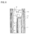
- An upper end part 122a of the ventilation path 122 bends in a crank shape as shown in FIG. 6 , and leads to the outside of the housing 12 through a ventilation hole 62 (cf. FIG. 8 ) provided on an upper surface 21a of the frame member 21 of the base 2. It is similar about an upper end part 123a of the ventilation path 123.
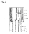
- a lower end part 122b of the ventilation path 122 leads to the outside of the housing 12 through the ventilation hole 61 of the ventilation plate 6 placed below the image display device 1.
- a plurality of heat pipes 13 are arranged in the flow path portion 11c of the circulation flow path 92.
- the plurality of heat pipes 13 is fixed to the rear surface 111 of the image display panel 11 being repeatedly arranged at a predetermined interval in the generally vertical direction as shown in FIG. 4 .
- one set of the heat pipes 13 arranged in such a manner is provided on either side of a centerline 111a of the rear surface 111.
- the heat pipe 13 arranged on the ventilation path 122 side of the centerline 111a passes through one of the side surface walls 121a forming the accommodation room 121 to extend from the inside of the accommodation room 121 to the inside of the ventilation path 122.
- the heat pipe 13 extends from the rear surface 111 of the image display panel 11 towards the ventilation path 122, and passes through the one of the side surface walls 121a to project into the inside of the ventilation path 122.
- a through-hole through which each of the heat pipes 13 passes.
- the through-hole is sealed by silicon rubber or the like with the heat pipe 13 passing therethrough. The inside of the accommodation room 121 is thereby maintained in the sealed state.
- the heat pipe 13 arranged on the ventilation path 123 side of the centerline 111a passes through the other side surface wall 121b forming the accommodation room 121 to extend from the inside of the accommodation room 121 into the inside of the ventilation path 123 in a similar manner to the heat pipe 13 extending into the ventilation path 122 (cf. FIG. 5 ).
- the heat generated from the image display panel 11 can be collected in the inside of the accommodation room 121.
- the heat can be collected from the air flowing through the circulation flow path 92 by the heat pipes 13, and the heat of the image display panel 11 can be collected directly from the rear surface 111 by the heat pipes 13.
- the collected heat is led to the outside of the accommodation room 121 by the heat pipes 13 to be released to the inside of the ventilation paths 122, 123.
- each heat pipes 13 functions as heat exchange means included in the image display device 1.
- the heat released from the heat pipes 13 to the inside of the ventilation paths 122, 123 is released to the outside of the housing 12 through the ventilation paths 122, 123. Therefore, the temperature increase of the image display panel 11 is restrained. As a result, the function of the liquid crystal display 10 is maintained in a preferable state.
- the heat pipes 13 are arranged in repetition on the rear surface 111 of the image display panel 11 at the predetermined interval, it is possible to collect the heat from the whole flow path portion 11c of the circulation flow path 92 and from the whole rear surface 111 of the image display panel 11. Cooling efficiency of the image display device 1 thereby becomes higher.
- each of the heat pipes 13 Since a refrigerant (water or the like) for heat exchange is filled in the inside of each heat pipe 13, it is preferable to arrange each of the heat pipes 13 diagonally as shown in FIG. 4 from a point of view of increasing the heat exchange efficiency of the heat pipe 13.
- the diagonally arranged heat pipes 13 extend from the inside of the accommodation room 121 to the inside of the ventilation paths 122, 123 obliquely upward.
- each heat pipe 13 located inside the ventilation paths 122, 123 is thereby at a higher place than a part (a high temperature part) located inside the accommodation room 121 in the generally vertical direction. Therefore, the refrigerant in the heat pipe 13 is evaporated in the high temperature part, to rise toward the low temperature part, and then, liquefied in the low temperature part to flow down towards the high temperature part, and it is evaporated in the high temperature part again.
- the refrigerant circulates through the heat pipe 13 efficiently, and the heat exchange efficiency of the heat pipe 13 increases.
- the heat pipes 13 are arranged on the rear surface 111 of the image display panel 11, it is possible to avoid limit on the display screen 112 due to the arrangement of the heat pipe 13, e.g., a reduction in size of the display screen 112 or the increase in size of the image display device 1.
- each of the heat pipes 13 described above is arranged along the rear surface 111 of the image display panel 11 from a point of view of increasing collecting efficiency of the heat from the rear surface 111 of the image display panel 11.
- a step is formed on the rear surface 111 of the image display panel 11 as shown in FIGS. 5 and 10 due to a relation between a mounting location of the image display panel 11 and mounting locations of electronic parts and the circuit board 11e mounted on the image display device 1.
- Each of the heat pipes 13 is bent in a crank shape in the step part so that the heat pipe 13 follows the shape of the rear surface 111 of the image display panel 11.
- each of the heat pipes 13 is arranged in repetition at the predetermined interval in the generally vertical direction as shown in FIG. 4 , and extends to the inside of the ventilation paths 122, 123 while keeping a distance with the adjacent heat pipe 13 at a predetermined interval.
- the heat pipes 13 are arranged in repetition at a predetermined interval in the generally vertical direction also in the inside of the ventilation paths 122, 123.
- the heat collected by the heat pipes 13 can be released dispersedly in the inside of the ventilation paths 122, 123.
- the heat exchange (heat dissipation) efficiency of the heat pipes 13 in the inside of the ventilation paths 122, 123 increases.
- the air conditioning machine 19 comprises an evaporator 191 and a condenser 192 which are heat exchangers as shown in FIG. 2 and FIGS. 10 to 12 . Heat is collected by the evaporator 191, and the collected heat can be released by the condenser 192.
- the evaporator 191 is arranged in the inside of the accommodation room 121 at a position on the rear surface 111 side of the image display panel 11 and adjacent to the lower end surface 114 of the image display panel 11 as shown in FIGS. 11 and 12 .
- the evaporator 191 is arranged in the lower end part of the flow path portion 11c of the circulation flow path 92.
- the circulation flow path 92 can be shortened by arranging the evaporator 191 on the rear surface 111 side, rather than the lower end surface 114 side, of the image display panel 11.
- the condenser 192 is arranged at a position inside the housing 12 and outside the accommodation room 121.
- the condenser 192 is arranged at a position below the accommodation room 121, i.e., a position below the image display panel 11.
- the condenser 192 is arranged opposed to the ventilation plate 6.
- the air conditioning machine 19 functions as the heat exchanger included in the image display device 1.
- the air conditioning machine 19 is used as the heat exchanger collecting heat from the air in the circulation flow path 92, but another heat exchanger may be adopted instead of the air conditioning machine 19.
- the air conditioning machine 19 may comprise a compressor along with the evaporator 191 and the condenser 192.
- the compressor is arranged at a position below the display panel 11, in particular, a position below the accommodation room 121.
- the air which circulates through the circulation flow path 92 and flowed into the air conditioning machine 19 is cooled by the evaporator 191, while the refrigerant in the evaporator 191 is evaporated by the heat from the air.
- the evaporated refrigerant is compressed by the compressor to be in a condition of the elevated temperature and pressure, and then flows into the condenser 192.
- the condenser 192 the refrigerant of the elevated temperature and pressure is cooled to generate a liquid refrigerant at low temperature. And then, the liquid refrigerant flows into the evaporator 191 again to cool the air in the circulation flow path 92.
- the circulation fans 18, 181 are fans for circulating the air in the circulation flow path 92 along the circulation flow path 92. As shown in FIGS. 11 and 12 , the circulation fans 18 are arranged at a position on the rear surface 111 side of the image display panel 11 and adjacent to the upper end surface 113 of the image display panel 11. In other words, the circulation fans 18 are arranged in the upper end part of the flow path portion 11c of the circulation flow path 92.
- the circulation fans 18 make the air in the flow path portion 11c of the circulation flow path 92 flow downward as shown in FIG. 13 .
- the circulation fans 181 are arranged in the inside of the accommodation room 121 on the rear surface 111 side of the image display panel 11 and adjacent to the evaporator 191. In this embodiment, as shown in FIGS. 11 and 12 , the circulation fans 181 are arranged at positions in the lower end part of the flow path portion 11c of the circulation flow path 92 and above the evaporator 191.
- the circulation fan 181 sends wind toward the evaporator 191 as shown in FIG. 14 .
- the circulation fan 181 has a function to draw the air from the upper part of the circulation flow path 92.
- the air in the circulation flow path 92 thereby circulates around the image display panel 11 in a direction of the solid line arrows.
- the air in the flow path portion 11a along the display screen 112 of the image display panel 11 flows from bottom to top in the generally vertical direction and passes through the flow path portion 11b along the upper end surface 113 of the image display panel 11 to flow into the path portion 11c along the rear surface 111 as shown in FIG. 13 .
- the air which flowed into the flow path portion 11c flows from top to bottom along the flow path portion 11c and passes through the flow path portion 11d along the lower end surface 114 of the image display panel 11 to return to the flow path portion 11a as shown in FIG. 14 .
- the air in the flow path portion 11a along the display screen 112 of the image display panel 11 can be led to the flow path portion 11c along the rear surface 111 efficiently. Therefore, the heat generated in a part adjacent to the display screen 112 of the image display panel 11 is collected by the heat pipes 13 arranged in the rear surface 111 side of the image display panel 11 and the evaporator 191 efficiently. In other words, by using the air in the circulation flow path 92, it is possible to air-cool the image display panel 11, in particular, the display screen 112 of the image display panel 11.
- the circulation fans 18, 181 are arranged in the upper end part and the lower end of the flow path portion 11c respectively, the air is easy to flow along the circulation flow path 92, and the flow speed increases. Therefore, the image display panel 11 can be cooled uniformly, and as a result, it does not happen that only a part of the image display panel 11 adjacent to the evaporator 191 is cooled.
- the air in the flow path portion 11a along the display screen 112 of the image display panel 11 flows from bottom to top in the generally vertical direction. Therefore, also due to a property of the air of rising when warmed by heat, the air in the flow path portion 11a flows from bottom to top efficiently.
- the air is easy to circulate along the circulation flow path 92, and the heat generated in a part adjacent to the display screen 112 of the image display panel 11 can be led to the heat pipes 13 and the evaporator 191 efficiently.
- the heat exchange (heat collection) efficiency in the heat pipes 13 and the evaporator 191 increases, thereby increasing the cooling efficiency of the image display device 1.
- the air in the circulation flow path 92 can be circulated efficiently since the circulation fans 18 are arranged in the upper end part of the flow path portion 11c of the circulation flow path 92, namely at a position adjacent to the flow path portion 11b along the upper end surface 113 of the image display panel 11. The reason is described below.
- a path resistance decreases.
- the circulation flow path 92 is narrow in the flow path portion 11b and is widened at the entrance to the flow path portion 11c from the flow path portion 11b as shown in FIG. 13 .
- the air in the flow path portion 11b is easy to be led to the flow path portion 11c.
- the circulation fans 18 in the upper end part of the flow path portion 11c, the air in the flow path portion 11b can be led to the flow path portion 11c efficiently. As a result, the air in the circulation flow path 92 circulates efficiently.
- the circulation fans 18 may be arranged at or in the vicinity of a position where the air flows out from the flow path portion 11a for the same reason as above.
- the circulation fans 18, 181 are arranged in the rear surface 111 side of the image display panel 11, it is possible to avoid an increase in size of the image display device 1 in the height direction.
- the circulation fans 18, 181 are used as the circulating means for circulating the air in the circulation flow path 92, but another circulating means may be employed instead of the circulation fans 18, 181.
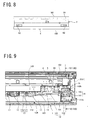
- the heat releasing fin 14 is arranged in the inside of the ventilation path 122 as shown in FIG. 9 , and is connected to a projecting part 131 of the heat pipe 13 projecting to the inside of the ventilation path 122.
- the heat releasing fin 14 is formed of aluminum.
- each of the heat releasing fins 14 comprises a first heat releasing part 141 and a second heat releasing part 142 sandwiching the projecting part 131 of the heat pipe 13 from both sides.
- the first heat releasing part 141 includes a base part 141a and a fin part 141b coupled with the base part 141a perpendicularly, and is arranged on a front surface of the housing 12 side of the projecting part 131 of the heat pipe 13.
- the second heat releasing part 142 includes a base part 142a and a fin part 142b coupled with the base part 142a perpendicularly, and is arranged on a rear surface side of the housing 12 side of the projecting part 131 of the heat pipe 13.
- a pair of grooves 141c, 142c as shown in FIGS. 17 and 18 .
- the projecting part 131 of the heat pipe 13 fits in the pair of grooves 141c, 142c when the projecting part 131 is sandwiched by the first heat releasing part 141 and the second heat releasing part 142 from both sides.
- the pair of grooves 141c, 142c is formed in the shape of a semicylinder, and when the projecting part 131 of the heat pipe 13 is sandwiched from both sides by the first heat releasing part 141 and the second heat releasing part 142, a cylindrical hole is formed by the pair of grooves 141c, 142c, and the projecting part 131 of the heat pipe 13 fits in the cylindrical hole.
- the plurality of heat pipes 13 are arranged on the rear surface 111 of the image display panel 11 in line in the generally vertical direction (cf. FIG. 4 ), and the plurality of heat releasing fins 14 corresponding to the plurality of heat pipes 13 are arranged inside the ventilation path 122 in the generally vertical direction.
- a plurality of first heat releasing parts 141 corresponding to the plurality of heat pipes 13 are formed integrally, and a plurality of second heat releasing parts 142 corresponding to the plurality of heat pipes 13 are also formed integrally.
- the heat releasing fins 14 are arranged in the inside the ventilation path 123 also (cf. for example, FIG. 4 ).
- the heat releasing fins 14 described above By using the heat releasing fins 14 described above, the heat dissipation efficiencies from the heat pipes 13 to the inside of the ventilation paths 122, 123 increase, resulting in the increase in the cooling efficiency of the image display device 1.
- each of the heat releasing fins 14 comprises the first heat releasing part 141 and the second heat releasing part 142, and the pair of grooves 141c, 142c is formed in the first heat releasing part 141 and second heat releasing part 142. And therefore, by simply sandwiching the heat pipe 13 from both sides by the first heat releasing part 141 and the second heat releasing part 142 to make the heat pipe 13 fitted in the pair of grooves 141c, 142c, it is possible to connect the heat releasing fins 14 to the heat pipe 13 while forming the heat releasing fins 14. Therefore, it is easy to connect the heat releasing fins 14 to the heat pipe 13.
- the plurality of first heat releasing parts 141 corresponding to the plurality of heat pipes 13 are formed integrally, and the plurality of second heat releasing parts 142 corresponding to the plurality of the heat pipes 13 are also formed integrally. Therefore, it is possible to attach the heat releasing fin 14 to all the plurality of heat pipes 13 each by performing one operation of sandwiching the plurality of heat pipes 13 with the first heat releasing parts 141 and the second heat releasing parts 142. As a result, installation of the heat releasing fins 14 to the plurality of heat pipes 13 is simplified.
- each first heat releasing part 141 a plurality of fin parts 141b are coupled with the base part 141a perpendicularly as shown in FIG. 17 , and a gap is defined between the fin parts 141b. This is similar in each second heat releasing part 142.
- the air flowing through the ventilation paths 122, 123 flows through the gap described above.
- tips of the plurality of fin parts 141b are coupled with each other by a coupling part in each first heat releasing part 141, and the gap mentioned above is surrounded by the fin part 141b, the base part 141a and the coupling part.
- This is similar in each second heat releasing part 142.
- the heat releasing fins 14 as duct fins which function also as ducts by making the air in the ventilation paths 122, 123 pass through only the said gap.
- the air in the ventilation paths 122, 123 may pass both through the gap and outside the gap.
- the heat releasing fin 14 is used as a heat releasing member for increasing the heat dissipation efficiency from the heat pipe 13 to the inside of the ventilation paths 122, 123, however, another heat releasing member may be employed instead of the heat releasing fin 14.
- the ventilation fans 15, 16 are arranged in the inside of the ventilation path 122 as shown in FIG. 4 , and the ventilation fan 15 is arranged in the upper end part 122a of the ventilation path 122, while the ventilation fan 16 is arranged in the lower end part 122b of the ventilation path 122.
- the ventilation fans 15, 16 make the air in the ventilation path 122 flow along the ventilation path 122 in the same direction.
- the ventilation fan 15 exhausts the air in the ventilation path 122 via the ventilation hole 62 to the outside of the housing 12 as shown in FIG. 6 , thereby making the air in the ventilation path 122 flow from bottom to top in the generally vertical direction.
- the ventilation fan 16 inhales the air outside the housing 12 via the ventilation hole 61 to the inside of the ventilation path 122 as shown in FIG. 7 , thereby making the air in the ventilation path 122 flow from bottom to top in the generally vertical direction.
- a flow of the air is indicated by solid line arrows.
- the ventilation fans 15, 16 are arranged in a similar manner to the ventilation path 122 (cf. FIG. 4 ), and the ventilation fans 15, 16 make the air in the ventilation path 123 flow from bottom to top in the generally vertical direction.
- the heat released to the inside of the ventilation paths 122, 123 from the heat pipes 13 can be dissipated to the outside of the housing 12 efficiently. Therefore, in the ventilation paths 122, 123, the heat dissipation efficiencies of the heat pipes 13 and the heat releasing fins 14 increase.
- the air in the ventilation paths 122, 123 flows from bottom to top, and therefore, also due to a property of the air of rising when warmed, the air in the ventilation paths 122, 123 warmed by the heat released to the inside of the ventilation paths 122, 123 flows from bottom to top efficiently. Therefore, the heat released within the ventilation paths 122, 123 can be dissipated to the outside of the housing 12 efficiently.
- the ventilation fans 15, 16 are used as fan means to exhaust the air in the ventilation paths 122, 123 to the outside of the housing 12, however, another fan means may be employed instead of the ventilation fans 15, 16.
- Each of the heat collecting fins 17 is connected to the plurality of heat pipes 13 in the inside of the accommodation room 121 as shown in FIG. 4 .
- each of the heat collecting fins 17 comprises a base part 171 and a fin part 172 as shown in FIG. 9 .
- the base part 171 extends over the plurality of heat pipes 13, and comes into contact with the plurality of heat pipes 13.
- the fin part 172 is coupled perpendicularly to the surface of the base part 171, and extends from one end of the base part 171 to the other end of the base part 171 in the longitudinal direction.
- the heat collecting fins 17 are connected only to the heat pipes 13 on the ventilation path 122 side of the centerline 111a. However, in reality, the heat collecting fins 17 are connected also to the heat pipes 13 on the ventilation path 123 side similarly.
- the heat collecting fin 17 is used as the heat collecting member for collecting heat from the air flowing through the circulation flow path 92, however, another heat collecting member may be employed instead of the heat collecting fin 17.
- the heat insulation member 7 is interposed between the evaporator 191 and the image display panel 11 as shown in FIG. 14 .
- the evaporator 191 is arranged in the rear surface 111 side of the image display panel 11, and the heat insulation member 7 is arranged between the rear surface 111 of the image display panel 11 and a front surface 191a of the evaporator 191.
- Urethane or silicon-based rubber is used, for example, for a material of the heat insulation member 7.
- the heat generated in the image display panel 11 is led to the evaporator 191 through the medium of the air flowing in the circulation flow path 92 and is collected by the evaporator 191.
- the heat insulation member 7 described above it is possible to prevent a part of the image display panel 11 adjacent to the evaporator 191 from being cooled excessively in a process of collecting heat by the evaporator 191. Therefore, a temperature distribution of the image display panel 11 becomes uniform, resulting in maintaining the function of the image display panel 11 in a preferable state.
- the rear surface wall 125 forming the accommodation room 121 includes a vertical wall part 125a and inclined wall parts 125b, 125c as shown in FIG. 12 .
- the vertical wall part 125a extends along the rear surface 111 of the image display panel 11.
- the inclined wall part 125b bends toward the backboard 3 from the upper end of the vertical wall part 125a and extends in the obliquely upward direction, while the inclined wall part 125c bends toward the backboard 3 from the lower end of the vertical wall part 125a and extends in the obliquely downward direction.
- First accommodation spaces 12b, 12c along the front surfaces of the inclined wall parts 125b, 125c respectively are thereby defined between the rear surface wall 125 and the rear surface 111 of the image display panel 11.
- the first accommodation spaces 12b, 12c are defined in the upper end part and the lower end part of the flow path portion 11c of the circulation flow path 92 respectively.
- a second accommodation space 12a along the rear surface of the vertical wall part 125a is defined between the rear surface wall 125 and the backboard 3.
- the circulation fan 18 is arranged in one of the first accommodation spaces 12b as shown in FIGS. 12 and 13 , while the circulation fan 181 and the evaporator 191 are arranged in the other first accommodation space 12c as shown in FIGS. 12 and 14 .
- the lighting apparatus 5 for illuminating the advertising film is arranged in the second accommodation space 12a as shown in FIG. 12 .
- a plurality of fluorescent lamps forming the lighting apparatus 5 are arranged in line horizontally along the vertical wall part 125a in the inside of the second accommodation space 12a.
- the first accommodation spaces 12b, 12c where the circulation fans 18, 181 and the evaporator 191 are arranged are defined inside the accommodation room 121
- the second accommodation space 12a where the lighting apparatus 5 are arranged is defined outside of the accommodation room 121 at a position generally below the circulation fans 18, and generally above the circulation fans 181 and the evaporator 191.
- the second accommodation space 12a is interposed between the first accommodation spaces 12b, 12c in the vertical direction or in the generally vertical direction.
- the plurality of heat pipes 13 are arranged in repetition at the predetermined interval in the generally vertical direction (cf. FIG. 4 ), however, this is not the limitation and there may be another embodiment.
- the heat pipes 13 may be arranged at different interval.
- the heat pipes 13 are arranged through the whole rear surface 111 of the image display panel 11 in a similar manner to the image display device 1 described above from a point of view of increasing the cooling efficiency of the image display device 1. The heat can be thereby collected from the whole rear surface 111 of the image display panel 11.
- the ventilation fans 15, 16 make the air in the ventilation paths 122, 123 flow from bottom to top, however, they may make the air flow from top to bottom.
- the air in the ventilation paths 122, 123 better flows from top to bottom in some cases.
- the number of ventilation fans to be provided to the ventilation paths 122, 123 may be one or may be three or more.
- the ventilation fans 15 are arranged in the upper end parts 122a, 123a of the ventilation paths 122, 123, and the ventilation fans 16 are arranged in the lower end parts 122b 123b of the ventilation paths 122, 123, however, they may be arranged in other positions, not limited to these positions. However, it is necessary to arrange them so that the air in the ventilation paths 122, 123 can be exhausted to the outside of the housing 12.
- the circulation flow path 92 comprises the flow path portion 11a along the display screen 112, the flow path portion 11b along the upper end surface 113, the flow path portion 11c along the rear surface 111, and the flow path portion 11d along the lower end face 114.
- another course surrounding the image display panel 11 in the inside of the accommodation room 121 may be used as the circulation flow path 92.
- flow path portions may be defined between the side surface of the image display panel 11 and the side surface walls 121a, 121b forming the accommodation room 121 respectively, to define the circulation flow path 92 by said flow path portions and the flow path portions 11a, 11c.
- the circulation fans 18 make the air in the flow path portion 11a along the display screen 112 flow from bottom to top, however, the circulation fans 18 may make the air flow from top to bottom. In such a case, it is preferable to install the circulation fan 18 in the position adjacent to the lower end surface 114 of the image display panel 11.
- the position of the circulation fans 18 is not limited to the position adjacent to the upper end surface 113 or the lower end surface 114 of the image display panel 11, and may be another position.
- the circulation fans 181 are arranged in the position above the evaporator 191 in the lower end part of the flow path portion 11c of the circulation flow path 92, however, the circulation fans 181 may be arranged in the position below the evaporator 191.
- the circulation fans 181 take in the air from the evaporator 191 according to such an embodiment, the air is sent into the evaporator 191 from above. Therefore, the heat can be collected by the evaporator 191 efficiently.
- the heat releasing fins 14 arranged inside the ventilation path 122 is formed by the first heat releasing part 141 and the second heat releasing part 142, and the projecting part 131 of the heat pipe 13 is sandwiched from both sides by the first heat releasing part 141 and the second heat releasing part 142 with the projecting part 131 fitted in the pair of grooves 141c, 142c.
- each heat releasing fin 14 is formed only by the first heat releasing part 141, and the heat releasing fin 14 is attached to the projecting part 131 of the heat pipe 13 by fitting the projecting part 131 of the heat pipe 13 in the groove 141c defined in the first heat releasing part 141.
- the present invention is not limited to the foregoing embodiment in construction but can be modified variously within the technical scope set forth in the appended claims.
- the technique can be applied in an image display device which includes the flat-panel display such as a plasma display or an organic electroluminescence (Electro-Luminescence) display.
- the circulation fans 18 are provided in order to circulate the air around the image display panel 11, however, the present invention is not limited to this.
- the fans 18 may be provided in order to form a flow of the air only on the display screen 112 of the image display panel 11. In such a case, the air drawn into the fans 18 is exhausted to the outside, for example, from the upper part of the image display device 1.
Landscapes
- Physics & Mathematics (AREA)
- Engineering & Computer Science (AREA)
- Chemical & Material Sciences (AREA)
- Crystallography & Structural Chemistry (AREA)
- Nonlinear Science (AREA)
- General Physics & Mathematics (AREA)
- Thermal Sciences (AREA)
- Microelectronics & Electronic Packaging (AREA)
- Mathematical Physics (AREA)
- Optics & Photonics (AREA)
- Theoretical Computer Science (AREA)
- Devices For Indicating Variable Information By Combining Individual Elements (AREA)
Applications Claiming Priority (1)
| Application Number | Priority Date | Filing Date | Title |
|---|---|---|---|
| JP2008255677A JP5241414B2 (ja) | 2008-09-30 | 2008-09-30 | 画像表示装置 |
Publications (1)
| Publication Number | Publication Date |
|---|---|
| EP2169452A1 true EP2169452A1 (en) | 2010-03-31 |
Family
ID=41354104
Family Applications (1)
| Application Number | Title | Priority Date | Filing Date |
|---|---|---|---|
| EP09012212A Withdrawn EP2169452A1 (en) | 2008-09-30 | 2009-09-25 | Display device |
Country Status (4)
| Country | Link |
|---|---|
| US (1) | US20100079948A1 (zh) |
| EP (1) | EP2169452A1 (zh) |
| JP (1) | JP5241414B2 (zh) |
| CN (1) | CN101714320B (zh) |
Cited By (1)
| Publication number | Priority date | Publication date | Assignee | Title |
|---|---|---|---|---|
| EP2194520A1 (en) * | 2008-12-04 | 2010-06-09 | SANYO Electric Co., Ltd. | Display apparatus and display system |
Families Citing this family (6)
| Publication number | Priority date | Publication date | Assignee | Title |
|---|---|---|---|---|
| KR101179041B1 (ko) | 2010-12-01 | 2012-09-03 | 주식회사 케이에스비 | 냉각모듈 공조시스템을 적용한 엘시디 및 엘이디 디지털 전광판 |
| KR101737391B1 (ko) * | 2011-02-01 | 2017-05-30 | 삼성전자주식회사 | 실외 디스플레이 장치 |
| KR101791914B1 (ko) * | 2011-04-01 | 2017-11-01 | 삼성전자주식회사 | 디스플레이 장치 |
| JP1713678S (ja) * | 2019-09-26 | 2022-04-26 | 電子看板 | |
| USD949973S1 (en) * | 2019-11-28 | 2022-04-26 | Lg Electronics Inc. | Digital signage |
| USD958246S1 (en) * | 2020-03-11 | 2022-07-19 | Ambow Sihua Intelligent Technology Co., Ltd. | Vertical display device |
Citations (3)
| Publication number | Priority date | Publication date | Assignee | Title |
|---|---|---|---|---|
| EP1408476A1 (en) | 2002-10-10 | 2004-04-14 | Barco N.V. | Light emission display arrangements |
| GB2402205A (en) | 2003-05-20 | 2004-12-01 | Densitron Technologies Plc | A display system cabinet and display system including heat removal means |
| US20090129021A1 (en) * | 2007-11-16 | 2009-05-21 | Manufacturing Resources International, Inc. | Gas station television |
Family Cites Families (54)
| Publication number | Priority date | Publication date | Assignee | Title |
|---|---|---|---|---|
| JPS6281874U (zh) * | 1985-11-05 | 1987-05-25 | ||
| JP3017837B2 (ja) * | 1991-05-31 | 2000-03-13 | 株式会社日立製作所 | 電子機器装置 |
| JP2583504Y2 (ja) * | 1992-02-14 | 1998-10-22 | 小糸工業株式会社 | 情報表示装置 |
| US5383340A (en) * | 1994-03-24 | 1995-01-24 | Aavid Laboratories, Inc. | Two-phase cooling system for laptop computers |
| JP3234740B2 (ja) * | 1994-06-09 | 2001-12-04 | キヤノン株式会社 | 画像表示装置 |
| US5606341A (en) * | 1995-10-02 | 1997-02-25 | Ncr Corporation | Passive CPU cooling and LCD heating for a laptop computer |
| JPH09307257A (ja) * | 1996-05-20 | 1997-11-28 | Fujitsu General Ltd | 映像表示装置 |
| US6212069B1 (en) * | 1996-08-23 | 2001-04-03 | Speculative Incorporated | Thermally efficient portable computer incorporating deploying CPU module |
| DE19704485C2 (de) * | 1997-02-07 | 1998-11-19 | Siemens Ag | Stromzuführungsvorrichtung für eine gekühlte elektrische Einrichtung |
| TW445386B (en) * | 1998-03-16 | 2001-07-11 | Hitachi Ltd | Thin-type display |
| TW393666B (en) * | 1998-06-15 | 2000-06-11 | Acer Display Tech Inc | A plasma display device having a heated airflow guiding groove |
| US6288896B1 (en) * | 1998-07-02 | 2001-09-11 | Acer Incorporated | Heat dissipation system for a laptop computer using a heat pipe |
| US6392883B1 (en) * | 2000-06-30 | 2002-05-21 | Intel Corporation | Heat exchanger having phase change material for a portable computing device |
| GB0020171D0 (en) * | 2000-08-17 | 2000-10-04 | Univ South Bank | Cooling method |
| JP4310039B2 (ja) * | 2000-09-29 | 2009-08-05 | エーユー オプトロニクス コーポレイション | Icの放熱構造および表示装置 |
| JP2002158475A (ja) * | 2000-11-20 | 2002-05-31 | Fujitsu General Ltd | 平面表示装置用密閉筐体 |
| JP3594900B2 (ja) * | 2000-12-19 | 2004-12-02 | 株式会社日立製作所 | ディスプレイ装置一体型コンピュータ |
| US6493440B2 (en) * | 2001-04-23 | 2002-12-10 | Gilbarco Inc. | Thermal management for a thin environmentally-sealed LCD display enclosure |
| US6698224B2 (en) * | 2001-11-07 | 2004-03-02 | Hitachi Kokusai Electric Inc. | Electronic apparatus having at least two electronic parts operating at different temperatures |
| JP2003324174A (ja) * | 2002-04-30 | 2003-11-14 | Toshiba Corp | 電子機器 |
| US6674642B1 (en) * | 2002-06-27 | 2004-01-06 | International Business Machines Corporation | Liquid-to-air cooling system for portable electronic and computer devices |
| JP3600606B2 (ja) * | 2002-09-20 | 2004-12-15 | 株式会社東芝 | 電子機器 |
| JP2004139187A (ja) * | 2002-10-15 | 2004-05-13 | Toshiba Corp | 電子機器 |
| US6816371B2 (en) * | 2002-12-16 | 2004-11-09 | International Business Machines Corporation | Method and arrangement for enhancing the cooling capacity of portable computers |
| TW577684U (en) * | 2003-06-30 | 2004-02-21 | Malico Inc | Heat dissipation module of flat display device |
| CN100426187C (zh) * | 2003-09-19 | 2008-10-15 | 富士通株式会社 | 电子装置 |
| KR100589313B1 (ko) * | 2003-09-24 | 2006-06-14 | 삼성에스디아이 주식회사 | 플라즈마 디스플레이 장치 |
| KR100556774B1 (ko) * | 2003-11-07 | 2006-03-10 | 엘지전자 주식회사 | 텔레비전을 구비한 냉장고 |
| US7288895B2 (en) * | 2003-11-17 | 2007-10-30 | Intel Corporation | System to improve display efficiency based on recycling local heat source |
| KR20060032480A (ko) * | 2004-10-12 | 2006-04-17 | 삼성전자주식회사 | 옥외용 디스플레이장치 |
| SI21941B (sl) * | 2004-11-03 | 2013-06-28 | Andraž Ogorevc | Javni prikazovalnik |
| KR100649598B1 (ko) * | 2004-12-29 | 2006-11-27 | 엘지전자 주식회사 | 플라즈마 디스플레이 패널 텔레비전의 방열구조 |
| JP2006267622A (ja) * | 2005-03-24 | 2006-10-05 | Sony Corp | ランプ冷却装置及び投射型表示装置 |
| JP2008084916A (ja) * | 2006-09-26 | 2008-04-10 | Sanyo Electric Co Ltd | 冷却装置 |
| US7457113B2 (en) * | 2006-10-11 | 2008-11-25 | International Business Machines Corporation | Venturi bernoulli heat extraction system for laptop computers |
| US7532467B2 (en) * | 2006-10-11 | 2009-05-12 | Georgia Tech Research Corporation | Thermal management devices, systems, and methods |
| TW200819878A (en) * | 2006-10-19 | 2008-05-01 | Hannspree Inc | sealing mechanism of flat panel display |
| KR101273592B1 (ko) * | 2007-01-08 | 2013-06-11 | 삼성전자주식회사 | 패널형 디스플레이장치 |
| JP4516582B2 (ja) * | 2007-05-15 | 2010-08-04 | 株式会社日立製作所 | 液晶表示装置 |
| KR101407622B1 (ko) * | 2007-11-09 | 2014-06-13 | 삼성디스플레이 주식회사 | 표시 장치 |
| US8711321B2 (en) * | 2007-11-16 | 2014-04-29 | Manufacturing Resources International, Inc. | System for thermally controlling displays |
| US8879042B2 (en) * | 2007-11-16 | 2014-11-04 | Manufacturing Resources International, Inc. | Isolated cooling system having an insulator gap and front polarizer |
| US8767165B2 (en) * | 2007-11-16 | 2014-07-01 | Manufacturing Resources International, Inc. | Isolated gas cooling system for an electronic display |
| US8379182B2 (en) * | 2007-11-16 | 2013-02-19 | Manufacturing Resources International, Inc. | Cooling system for outdoor electronic displays |
| US20090126914A1 (en) * | 2007-11-16 | 2009-05-21 | Manufacturing Resources International, Inc. | Isolated Gas Cooling System for Cooling Electrical Components of an Electronic Display |
| US8373841B2 (en) * | 2007-11-16 | 2013-02-12 | Manufacturing Resources International, Inc. | Shared isolated gas cooling system for oppositely facing electronic displays |
| US8854595B2 (en) * | 2008-03-03 | 2014-10-07 | Manufacturing Resources International, Inc. | Constricted convection cooling system for an electronic display |
| US8351014B2 (en) * | 2008-03-03 | 2013-01-08 | Manufacturing Resources International, Inc. | Heat exchanger for back to back electronic displays |
| US8274622B2 (en) * | 2008-03-03 | 2012-09-25 | Manufacturing Resources International, Inc. | System for using constricted convection with closed loop plenum as the convection plate |
| US8654302B2 (en) * | 2008-03-03 | 2014-02-18 | Manufacturing Resources International, Inc. | Heat exchanger for an electronic display |
| US8016452B2 (en) * | 2008-03-26 | 2011-09-13 | Manufacturing Resources International, Inc. | Advertising displays |
| US8358397B2 (en) * | 2008-03-03 | 2013-01-22 | Manufacturing Resources International, Inc. | System for cooling an electronic display |
| US20090231807A1 (en) * | 2008-03-13 | 2009-09-17 | Bouissiere Michael F | Waterproof Ventilated Display Enclosure |
| EP2289236B1 (en) * | 2008-05-07 | 2017-03-29 | Civiq Smartscapes | Video display system |
-
2008
- 2008-09-30 JP JP2008255677A patent/JP5241414B2/ja not_active Expired - Fee Related
-
2009
- 2009-09-17 CN CN200910170897.1A patent/CN101714320B/zh active Active
- 2009-09-25 EP EP09012212A patent/EP2169452A1/en not_active Withdrawn
- 2009-09-30 US US12/570,322 patent/US20100079948A1/en not_active Abandoned
Patent Citations (3)
| Publication number | Priority date | Publication date | Assignee | Title |
|---|---|---|---|---|
| EP1408476A1 (en) | 2002-10-10 | 2004-04-14 | Barco N.V. | Light emission display arrangements |
| GB2402205A (en) | 2003-05-20 | 2004-12-01 | Densitron Technologies Plc | A display system cabinet and display system including heat removal means |
| US20090129021A1 (en) * | 2007-11-16 | 2009-05-21 | Manufacturing Resources International, Inc. | Gas station television |
Cited By (1)
| Publication number | Priority date | Publication date | Assignee | Title |
|---|---|---|---|---|
| EP2194520A1 (en) * | 2008-12-04 | 2010-06-09 | SANYO Electric Co., Ltd. | Display apparatus and display system |
Also Published As
| Publication number | Publication date |
|---|---|
| JP5241414B2 (ja) | 2013-07-17 |
| US20100079948A1 (en) | 2010-04-01 |
| JP2010085780A (ja) | 2010-04-15 |
| CN101714320A (zh) | 2010-05-26 |
| CN101714320B (zh) | 2014-07-02 |
Similar Documents
| Publication | Publication Date | Title |
|---|---|---|
| US8144468B2 (en) | Display device | |
| US8274789B2 (en) | Display device | |
| US7995342B2 (en) | Display device | |
| US8746912B2 (en) | Display device having an advertizing part | |
| US8724321B2 (en) | Display apparatus | |
| EP2214462B1 (en) | Display apparatus and display system | |
| US8760867B2 (en) | Display apparatus | |
| EP2169452A1 (en) | Display device | |
| EP2194520A1 (en) | Display apparatus and display system | |
| JP5317656B2 (ja) | 画像表示装置 | |
| EP2214465A2 (en) | Display apparatus | |
| JP5317657B2 (ja) | 画像表示装置 | |
| JP5268679B2 (ja) | 画像表示装置 | |
| JP5164814B2 (ja) | 画像表示システム | |
| JP2010134200A (ja) | 画像表示装置 | |
| JP2010134199A (ja) | 待合いユニット |
Legal Events
| Date | Code | Title | Description |
|---|---|---|---|
| PUAI | Public reference made under article 153(3) epc to a published international application that has entered the european phase |
Free format text: ORIGINAL CODE: 0009012 |
|
| AK | Designated contracting states |
Kind code of ref document: A1 Designated state(s): AT BE BG CH CY CZ DE DK EE ES FI FR GB GR HR HU IE IS IT LI LT LU LV MC MK MT NL NO PL PT RO SE SI SK SM TR |
|
| AX | Request for extension of the european patent |
Extension state: AL BA RS |
|
| 17P | Request for examination filed |
Effective date: 20100930 |
|
| 17Q | First examination report despatched |
Effective date: 20101026 |
|
| STAA | Information on the status of an ep patent application or granted ep patent |
Free format text: STATUS: THE APPLICATION HAS BEEN WITHDRAWN |
|
| 18W | Application withdrawn |
Effective date: 20130603 |