EP2161215B1 - Display-Verpackung für Fahrradgriffe - Google Patents
Display-Verpackung für Fahrradgriffe Download PDFInfo
- Publication number
- EP2161215B1 EP2161215B1 EP09167777A EP09167777A EP2161215B1 EP 2161215 B1 EP2161215 B1 EP 2161215B1 EP 09167777 A EP09167777 A EP 09167777A EP 09167777 A EP09167777 A EP 09167777A EP 2161215 B1 EP2161215 B1 EP 2161215B1
- Authority
- EP
- European Patent Office
- Prior art keywords
- connection arm
- receiving element
- display packing
- display
- packing according
- Prior art date
- Legal status (The legal status is an assumption and is not a legal conclusion. Google has not performed a legal analysis and makes no representation as to the accuracy of the status listed.)
- Active
Links
- 238000004806 packaging method and process Methods 0.000 title description 74
- 238000004026 adhesive bonding Methods 0.000 claims description 7
- 239000011324 bead Substances 0.000 claims description 7
- 238000012856 packing Methods 0.000 claims 29
- 238000006073 displacement reaction Methods 0.000 claims 1
- 239000000853 adhesive Substances 0.000 description 14
- 230000001070 adhesive effect Effects 0.000 description 14
- 239000006260 foam Substances 0.000 description 4
- 239000000463 material Substances 0.000 description 3
- 229920003023 plastic Polymers 0.000 description 3
- 238000004519 manufacturing process Methods 0.000 description 2
- 238000005192 partition Methods 0.000 description 2
- 238000005520 cutting process Methods 0.000 description 1
- 230000006378 damage Effects 0.000 description 1
- 238000004049 embossing Methods 0.000 description 1
- 230000006870 function Effects 0.000 description 1
- 238000004064 recycling Methods 0.000 description 1
- 230000000717 retained effect Effects 0.000 description 1
- 230000035807 sensation Effects 0.000 description 1
- 125000006850 spacer group Chemical group 0.000 description 1
Images

Classifications
-
- B—PERFORMING OPERATIONS; TRANSPORTING
- B65—CONVEYING; PACKING; STORING; HANDLING THIN OR FILAMENTARY MATERIAL
- B65D—CONTAINERS FOR STORAGE OR TRANSPORT OF ARTICLES OR MATERIALS, e.g. BAGS, BARRELS, BOTTLES, BOXES, CANS, CARTONS, CRATES, DRUMS, JARS, TANKS, HOPPERS, FORWARDING CONTAINERS; ACCESSORIES, CLOSURES, OR FITTINGS THEREFOR; PACKAGING ELEMENTS; PACKAGES
- B65D73/00—Packages comprising articles attached to cards, sheets or webs
- B65D73/0064—Packages comprising articles attached to cards, sheets or webs the articles being supported by or suspended from a tag-like element
-
- B—PERFORMING OPERATIONS; TRANSPORTING
- B65—CONVEYING; PACKING; STORING; HANDLING THIN OR FILAMENTARY MATERIAL
- B65D—CONTAINERS FOR STORAGE OR TRANSPORT OF ARTICLES OR MATERIALS, e.g. BAGS, BARRELS, BOTTLES, BOXES, CANS, CARTONS, CRATES, DRUMS, JARS, TANKS, HOPPERS, FORWARDING CONTAINERS; ACCESSORIES, CLOSURES, OR FITTINGS THEREFOR; PACKAGING ELEMENTS; PACKAGES
- B65D25/00—Details of other kinds or types of rigid or semi-rigid containers
- B65D25/02—Internal fittings
- B65D25/10—Devices to locate articles in containers
- B65D25/106—Elements projecting into a recess or through a hole in the articles
-
- B—PERFORMING OPERATIONS; TRANSPORTING
- B65—CONVEYING; PACKING; STORING; HANDLING THIN OR FILAMENTARY MATERIAL
- B65D—CONTAINERS FOR STORAGE OR TRANSPORT OF ARTICLES OR MATERIALS, e.g. BAGS, BARRELS, BOTTLES, BOXES, CANS, CARTONS, CRATES, DRUMS, JARS, TANKS, HOPPERS, FORWARDING CONTAINERS; ACCESSORIES, CLOSURES, OR FITTINGS THEREFOR; PACKAGING ELEMENTS; PACKAGES
- B65D75/00—Packages comprising articles or materials partially or wholly enclosed in strips, sheets, blanks, tubes or webs of flexible sheet material, e.g. in folded wrappers
- B65D75/28—Articles or materials wholly enclosed in composite wrappers, i.e. wrappers formed by associating or interconnecting two or more sheets or blanks
- B65D75/30—Articles or materials enclosed between two opposed sheets or blanks having their margins united, e.g. by pressure-sensitive adhesive, crimping, heat-sealing, or welding
- B65D75/32—Articles or materials enclosed between two opposed sheets or blanks having their margins united, e.g. by pressure-sensitive adhesive, crimping, heat-sealing, or welding one or both sheets or blanks being recessed to accommodate contents
- B65D75/36—Articles or materials enclosed between two opposed sheets or blanks having their margins united, e.g. by pressure-sensitive adhesive, crimping, heat-sealing, or welding one or both sheets or blanks being recessed to accommodate contents one sheet or blank being recessed and the other formed of relatively stiff flat sheet material, e.g. blister packages, the recess or recesses being preformed
-
- B—PERFORMING OPERATIONS; TRANSPORTING
- B65—CONVEYING; PACKING; STORING; HANDLING THIN OR FILAMENTARY MATERIAL
- B65D—CONTAINERS FOR STORAGE OR TRANSPORT OF ARTICLES OR MATERIALS, e.g. BAGS, BARRELS, BOTTLES, BOXES, CANS, CARTONS, CRATES, DRUMS, JARS, TANKS, HOPPERS, FORWARDING CONTAINERS; ACCESSORIES, CLOSURES, OR FITTINGS THEREFOR; PACKAGING ELEMENTS; PACKAGES
- B65D2201/00—Means or constructions for testing or controlling the contents
-
- B—PERFORMING OPERATIONS; TRANSPORTING
- B65—CONVEYING; PACKING; STORING; HANDLING THIN OR FILAMENTARY MATERIAL
- B65D—CONTAINERS FOR STORAGE OR TRANSPORT OF ARTICLES OR MATERIALS, e.g. BAGS, BARRELS, BOTTLES, BOXES, CANS, CARTONS, CRATES, DRUMS, JARS, TANKS, HOPPERS, FORWARDING CONTAINERS; ACCESSORIES, CLOSURES, OR FITTINGS THEREFOR; PACKAGING ELEMENTS; PACKAGES
- B65D2575/00—Packages comprising articles or materials partially or wholly enclosed in strips, sheets, blanks, tubes or webs of flexible sheet material, e.g. in folded wrappers
- B65D2575/52—Details
- B65D2575/54—Cards, coupons, or other inserts or accessories
- B65D2575/56—Handles or other suspension means
- B65D2575/565—Handles or other suspension means means explicitly used for suspending
Definitions
- the invention relates to a display packaging for bicycle handles.
- display packaging products such as bicycle handles
- display packaging on a usually printed cardboard, which serves as a display element.
- the product itself is arranged for example in a transparent packaging body, which is connected to the cardboard, for example by gluing.
- Display packaging is used to package and promote the product.
- Such a display packaging for bicycle handles is off EP 1 609 736 known.
- This display packaging has a flat, consisting of cardboard, in particular printed display element. With this a transparent plastic element is connected, so that a packaging container is designed for one of the two bicycle grips.
- the first bicycle handle thus lies on the display element and is held by a plastic sleeve which is connected to the display element.
- an existing plastic, elongated base member is connected via two screws with the display element.
- the base member has an internally threaded cylindrical projection. In these a rod-shaped receiving element can be screwed.
- the rod-shaped receiving element has a to the display element Distance up.
- the rod-shaped receiving element of the second bicycle handle On the rod-shaped receiving element of the second bicycle handle is attached, wherein the rod-shaped receiving element has substantially the diameter of a bicycle handlebar.
- the second bicycle handle is thus arranged at a distance from the display element, so that a gripping opening between the second bicycle handle and the display element is formed. This makes it possible for a customer to be able to touch the second bicycle handle and thus be able to judge whether the particularly ergonomically designed shape of the bicycle handle has a pleasant gripping sensation for the customer.
- a disadvantage of this display packaging is that the packaging is relatively complex and therefore expensive.
- the object of the invention is to provide a more cost-effective display packaging.
- the display packaging for bicycle handles has a packaging space which is formed by a packaging container.
- the packaging space is used to hold at least a first bicycle handle and possibly for receiving accessories such as fasteners for the bicycle handle, possibly connected to the bicycle handle bar ends, assembly instructions, etc.
- the packaging container is connected via a connecting arm, a rod-shaped receiving element.
- the rod-shaped receiving element which is preferably round and has an outer diameter substantially corresponding to a bicycle handlebar, serves to receive the second bicycle handle.
- the second bicycle handle can be attached to the receiving element.
- the packaging container is integrally formed with the packaging arm. As a result, the production cost for the production of the display packaging is significantly reduced.
- the packaging container and the packaging arm exclusively made of a material that is easy to recycle, in particular exclusively made of cardboard. It is thus according to the invention in the packaging container together with the connecting arm to a single three-dimensional molded body.
- the rod-shaped receiving element made of cardboard. In particular, this is a cardboard tube.
- the packaging container forming the packaging container is closed in a preferred embodiment on its front side with a closure element.
- the closure element is preferably made of the same material as the packaging container and the connecting arm, in particular cardboard.
- the closure element is a relatively thin element having a planar top surface, the closure element in a preferred embodiment not only covering the front of the container, i. closes the packaging space but also extends over the front of the connecting arm. As a result, a uniform front of the entire display packaging is produced. This can be printed as a particularly uniformly closed display surface.
- the connecting arm is connected at an inclination angle greater than 0 ° to the packaging container.
- the connecting arm protrudes in this case preferably, based on the packaging container, forward, ie in the direction of the customer.
- the connecting arm thus projects towards the front of the packaging container to the front.
- the angle of inclination is greater than 20 ° and particularly preferably greater than 30 °.
- the angle is less than 90 °, in particular less than 60 °.
- the end region of the connecting arm is bent back in a preferred embodiment.
- the connecting arm is thus preferably S-shaped or substantially has an S-shaped center line.
- the inclination angle of the end member of the connecting arm is preferably smaller than that Tilt angle between the connecting arm and the packaging container.
- a front side of the end member of the connecting arm is aligned substantially parallel to the front of the packaging container.
- the connecting arm is hollow.
- the packaging space formed by the packaging container can merge into the hollow connecting arm. Possibly.
- a partition between the hollow connecting arm and the packaging space is provided to prevent small parts from getting out of the packaging space in the cavity of the connecting arm.
- the cavity of the connecting arm is closed by the closing element, wherein preferably a common closing element is provided, which closes the cavity of the connecting arm as well as the packaging space of the packaging container.
- the rod-shaped receiving element projects into the connecting arm.
- the connecting arm in particular in a pointing in the direction of the receiving element side wall of the hollow connecting arm on a receiving opening through which the rod-shaped receiving element is inserted into the connecting arm.
- the connection of the receiving element with the particular hollow connecting arm is an independent, independent of the design of the packaging space invention.
- the packaging space can also be completely eliminated, so that, for example, only a base element, for example in the form of a flat cardboard, is provided.
- the two handles are then optionally arranged on separate displays or on a common or two separate connecting arms, for example, opposite one another.
- a first end surface of the receiving member is preferably disposed within the connecting arm so as to abut against an inner surface of the connecting arm, in particular on the inner surface of a wall of the hollow connecting arm.
- the first end face in particular by an adhesive connection, be firmly connected.
- adhesive tabs can be arranged on the first end face of the receiving element.
- the adhesive tabs can be made by axially cutting a, in particular consisting of cardboard, tubular receiving element and folding the corresponding areas to the outside. As a result, an enlarged adhesive surface is realized.
- the fixing element is in this case preferably designed as a connecting bead, wherein the connecting bead, the rod-shaped receiving element in the region of the first end face preferably at least partially, in particular completely, i. ring-shaped, surrounds.
- the tantswulst can be generated by an adhesive foam. In particular, biodegradable adhesive foam is used here.
- a second fixing element is arranged on an inner side of the wall of the connecting arm having the receiving opening.
- the second fixing element is preferably connected to the receiving element and / or the inside of the wall. This is done in a particularly preferred embodiment, in turn, by a dacaswulst, the receiving element at least partially, in particular completely, ie annular surrounds.
- the connection bead is preferably also made of an adhesive bead, preferably using a biodegradable adhesive foam.
- a receiving element On an outer side of the receiving opening having the wall of the connecting arm is preferably a receiving element at least partially, in particular completely surrounding sleeve arranged.
- the sleeve may be firmly connected to the receiving element and / or the outside of the connecting arm, in particular by gluing.
- the housing then has an additional stiffening and connecting function.
- the sleeve serves as a spacer, so that the customer when gripping the plugged onto the receiving element second bicycle handle this not too close to the connecting arm touches. As a result, touching the connecting arm and possibly injuring the hand on the sharp-edged cardboard is avoided.
- the closing element preferably has an opening element in the region of the front side of the packaging container.
- This can be an embossing, a tear flap, a tear thread or the like. This makes it possible to open the packaging space, so that the first bicycle handle and the accessories can be removed from the packaging space through a removal opening.
- the provision of such an opening element has the advantage that the fixed connection between the closing element and the packaging container, which is in particular an adhesive connection, does not have to be destroyed. It is thus easy for the customer to open the packaging space.
- the receiving element, to which the second bicycle handle can be attached is preferably arranged at such a distance from the packaging container that a gripping opening is retained even when the bicycle handle is attached. This makes it possible for the customer to be able to grip the bicycle handle according to a bicycle handle mounted on a handlebar. Since, in a preferred embodiment, the connecting arm is inclined with respect to the packaging container to the front, in a particularly preferred embodiment, the receiving element is arranged offset from the packaging container to the front. In particular, the receiving element for Offset front of the packaging container such that the receiving element is preferably arranged completely outside the plane formed by the front. As a result, the presentation of the bicycle handle is improved and a gripping the bicycle handle from above possible. The grip of the bicycle handle is thus carried out by the customer by the same movement that the customer executes even when the bicycle handle is mounted on the handlebar.
- Another particular advantage of the display packaging according to the invention is that an extremely compact packaging is realized.
- the display packaging produced entirely from cardboard and biodegradable adhesive materials in a preferred embodiment has a packaging container 10.
- a packaging container 10 Within the packaging container 10, a not shown, first bicycle handle and accessories can be arranged.
- the accessories are, for example, bar ends, handlebar plugs, mounting clamps, etc.
- the packaging space 12 which is formed by the packaging container 10, the assembly instructions are arranged.
- the packaging container 10 is formed integrally with a connecting arm 14. Both the packaging container 10 and the connecting arm 14 are preferably made of cardboard as a three-dimensional molded body and preferably both hollow, wherein between the cavity of the connecting arm 14 and the packaging space 12, a partition wall may be provided.
- a receiving element 16 Connected to the connecting arm 14 is a receiving element 16 which is designed in particular as a cardboard tube, the receiving element 16 preferably being provided with an end region 18 (FIG. Fig. 4 ) of the connecting arm 14 is connected.
- a second bicycle handle 20 On the rod-shaped receiving element is a second bicycle handle 20 ( Fig. 6 ) attachable.
- a front side 22 of the packaging container 10 is closed with a closure element 24 likewise made of cardboard in a preferred embodiment.
- the closing element also extends over a front side 26 of the connecting arm 14, so that a self-contained display surface 22, 26 is formed.
- the closing element may be a three-dimensionally preformed cardboard element.
- the connecting element has a corresponding flexibility and by gluing with edges 28 ( Fig. 5 ) of the packaging container is fixed. A corresponding gluing also takes place in the region of the connecting arm.
- the rod-shaped receiving element 16 protrudes into a cavity 30 (FIG. Fig. 3 ) of the connecting arm 14.
- an inner, in the direction of Receiving element 16 facing wall 32 of the connecting arm 14 has a receiving opening 34.
- the diameter of the receiving opening 34 corresponds to the outer diameter of the receiving element 16.
- the receiving element 16 is inserted through the receiving opening 34 so far into the cavity 30, that a first end face 36 of the receiving element 16 on an inner surface 38 of an outer, facing away from the receiving element 16 side wall 40 of Connecting arm 14 is applied.
- the connection of the receiving element 16 via a first fixing member 42 and a second fixing member 44 takes place.
- the fixing elements 42, 44 to Vietnameseswulste which are preferably made of an adhesive foam, it being particularly preferred that It is a biodegradable adhesive.
- the two fixing elements 42, 44 are each connected to connect an outer side 46 of the rod-shaped receiving element 16 to an inner side 48 of the wall 32 or an inner side 50 of the wall 40.
- the connecting beads 42, 44 can be annular in circumference. Possibly.
- the kauswulste are only partially ring-shaped.
- a particular annular sleeve 62 is disposed on an outer side 60 of the wall 32.
- the sleeve 62 may be connected to the outside 60 of the wall 32 and / or the outside 46 of the receiving element 16, in particular by gluing.
- a midplane 52 ( Fig. 4 ) of the packaging container 10 has an angle ⁇ to a median plane 54 of the connecting arm 14. This is greater than 0 °, in particular greater than 30 °, so that, based on the packaging container 10, the connecting arm to the front, ie in the direction of an arrow 56 in Fig. 4 has.
- the end element 18 of the connecting arm is then again inclined slightly lower, wherein a median plane 58 of the end element with respect to the median plane 52 of the packaging container 10 has an angle which is smaller than the angle ⁇ . Possibly. the two planes 52, 58 are parallel to each other.
- the connecting arm is preferably in side view S-shaped in connection with the packaging container 10 or has an S-shaped center line.
- the closing element 24 can be opened via an opening element 64, such as a tear tab or a perforation. This creates a removal opening 66 (FIG. Fig. 5 ). By opening the removal opening 66, however, there is no destruction of the adhesive bond in the edge region 28 of the packaging container 10 in which it is glued to the closure element 24.
- the receiving element 16 which is designed in particular as a cardboard tube, is closed on its second end face by a closure element 68, which is in particular a lid made of cardboard.
- the closure element 68 may be connected to the inside of the receiving element 16 by gluing.
- bicycle handle When attached to the receiving element 16 bicycle handle ( Fig. 6 ) is formed between the second bicycle handle 20 and the packaging container 10, a gripping opening 70. It is thus possible for the customer in a simple manner, the bicycle handle 20 to handle and corresponding to a handle which is mounted on a handlebar to take.
Landscapes
- Engineering & Computer Science (AREA)
- Mechanical Engineering (AREA)
- Chemical & Material Sciences (AREA)
- Composite Materials (AREA)
- Cartons (AREA)
- Steering Devices For Bicycles And Motorcycles (AREA)
- Packaging Of Annular Or Rod-Shaped Articles, Wearing Apparel, Cassettes, Or The Like (AREA)
- Packaging Of Machine Parts And Wound Products (AREA)
Description
- Die Erfindung betrifft eine Display-Verpackung für Fahrradgriffe.
- Mit Display-Verpackungen werden Produkte, wie beispielsweise Fahrradgriffe, in Verkaufsräumen präsentiert. Beispielsweise weisen derartige Display-Verpackungen einen üblicherweise bedruckten Karton auf, der als Displayelement dient. Das Produkt selbst ist beispielsweise in einem durchsichtigen Verpackungskörper angeordnet, der mit dem Karton beispielsweise durch Kleben verbunden ist. Durch Display-Verpackungen erfolgt ein Verpacken sowie ein verkaufsförderndes Präsentieren des Produkts.
- Eine derartige Display-Verpackung für Fahrradgriffe ist aus
EP 1 609 736 bekannt. Diese Display-Verpackung weist ein ebenes, aus Karton bestehendes, insbesondere bedrucktes Displayelement auf. Mit diesem ist ein durchsichtiges Kunststoffelement verbunden, so dass ein Verpackungsbehälter für einen der beiden Fahrradgriffe ausgebildet ist. Der erste Fahrradgriff liegt somit auf dem Displayelement und ist von einer Kunststoffhülle, die mit dem Displayelement verbunden ist, gehalten. Ferner ist mit dem Displayelement ein aus Kunststoff bestehendes, längliches Basiselement über zwei Schrauben verbunden. Das Basiselement weist einen mit einem Innengewinde versehenen, zylindrischen Ansatz auf. In diesen ist ein stabförmiges Aufnahmeelement einschraubbar. Das stabförmige Aufnahmeelement weist zu dem Displayelement einen Abstand auf. Auf das stabförmige Aufnahmeelement ist der zweite Fahrradgriff aufgesteckt, wobei das stabförmige Aufnahmeelement im Wesentlichen den Durchmesser eines Fahrradlenkers aufweist. Der zweite Fahrradgriff ist somit in einem Abstand zu dem Displayelement angeordnet, so dass eine Greiföffnung zwischen dem zweiten Fahrradgriff und dem Displayelement ausgebildet ist. Hierdurch ist es möglich, dass ein Kunde den zweiten Fahrradgriff anfassen kann und somit beurteilen kann, ob die insbesondere ergonomisch ausgestaltete Form des Fahrradgriffs für den Kunden ein angenehmes Greifgefühl hat. Nachteilig bei dieser Display-Verpackung ist, dass die Verpackung relativ aufwändig und somit teuer ist. - Aufgabe der Erfindung ist es, eine kostengünstigere Display-Verpackung zu schaffen.
- Die Lösung der Aufgabe erfolgt erfindungsgemäß durch die Merkmale des Anspruchs 1.
- Die erfindungsgemäße Display-Verpackung für Fahrradgriffe weist einen Verpackungsraum auf, der durch einen Verpackungsbehälter gebildet ist. Der Verpackungsraum dient zur Aufnahme zumindest eines ersten Fahrradgriffs sowie ggf. zur Aufnahme von Zubehör, wie Befestigungselementen für den Fahrradgriff, ggf. mit dem Fahrradgriff verbundenen Lenkerhörnchen, der Montageanleitung etc. Mit dem Verpackungsbehälter ist über einen Verbindungsarm ein stabförmiges Aufnahmeelement verbunden. Das stabförmige Aufnahmeelement, das vorzugsweise rund ist und einen im Wesentlichen einem Fahrradlenker entsprechenden Außendurchmesser aufweist, dient zur Aufnahme des zweiten Fahrradgriffs. Der zweite Fahrradgriff kann auf das Aufnahmeelement aufgesteckt werden. Erfindungsgemäß ist der Verpackungsbehälter mit dem Verpackungsarm einstückig ausgebildet. Hierdurch ist der Fertigungsaufwand zur Herstellung der Display-Verpackung erheblich reduziert. Besonders bevorzugt ist es hierbei, dass der Verpackungsbehälter und der Verpackungsarm ausschließlich aus einem einfach zu recycelnden Material, insbesondere ausschließlich aus Pappe, hergestellt ist. Es handelt sich somit erfindungsgemäß bei dem Verpackungsbehälter zusammen mit dem Verbindungsarm um einen einzigen dreidimensionalen Formkörper. Um ein einfaches Recyceln, insbesondere der gesamten Display-Verpackung, zu ermöglichen, ist in besonders bevorzugter Ausführungsform auch das stabförmige Aufnahmeelement aus Pappe hergestellt. Insbesondere handelt es sich hierbei um ein Papprohr.
- Der den Verpackungsraum ausbildende Verpackungsbehälter ist in bevorzugter Ausführungsform an seiner Vorderseite mit einem Verschlusselement verschlossen. Das Verschlusselement ist vorzugsweise aus demselben Material, wie der Verpackungsbehälter und der Verbindungsarm, insbesondere Pappe. Vorzugsweise handelt es sich bei dem Verschlusselement um ein relativ dünnes, eine flächige Oberseite aufweisendes Element, wobei das Verschlusselement in bevorzugter Ausführungsform nicht nur die Vorderseite des Behälters, d.h. den Verpackungsraum verschließt sondern sich auch über die Vorderseite des Verbindungsarms erstreckt. Hierdurch wird eine einheitliche Vorderseite der gesamten Display-Verpackung erzeugt. Diese kann als insbesondere einheitlich geschlossene Displayfläche bedruckt werden.
- In bevorzugter Ausführungsform ist der Verbindungsarm in einem Neigungswinkel größer 0° mit dem Verpackungsbehälter verbunden. Der Verbindungsarm ragt hierbei vorzugsweise, bezogen auf den Verpackungsbehälter, nach vorne, d.h. in Richtung des Kunden. Der Verbindungsarm ragt somit gegenüber der Vorderseite des Verpackungsbehälters nach vorne. Insbesondere ist der Neigungswinkel größer 20° und besonders bevorzugt größer 30°. Vorzugsweise ist der Winkel jedoch kleiner als 90°, insbesondere kleiner als 60°. Der Endbereich des Verbindungsarms ist in bevorzugter Ausführungsform wieder zurückgebogen. In Seitenansicht ist der Verbindungsarm somit vorzugsweise S-förmig bzw. weist im Wesentlichen eine S-förmige Mittellinie auf. Der Neigungswinkel des Endelements des Verbindungsarms ist vorzugsweise geringer als der Neigungswinkel zwischen dem Verbindungsarm und dem Verpackungsbehälter. Vorzugsweise ist eine Vorderseite des Endelements des Verbindungsarms im Wesentlichen parallel zu der Vorderseite des Verpackungsbehälters ausgerichtet.
- In besonders bevorzugter Ausführungsform ist der Verbindungsarm hohl ausgebildet. Insbesondere kann der durch den Verpackungsbehälter ausgebildete Verpackungsraum in den hohlen Verbindungsarm übergehen. Ggf. ist zur Abgrenzung des Verpackungsraums eine Trennwand zwischen dem hohlen Verbindungsarm und dem Verpackungsraum vorgesehen, um zu vermeiden, dass Kleinteile aus dem Verpackungsraum in den Hohlraum des Verbindungsarms gelangen. Der Hohlraum des Verbindungsarms ist durch das Verschließelement verschlossen, wobei vorzugsweise ein gemeinsames Verschließelement vorgesehen ist, das den Hohlraum des Verbindungsarms sowie auch den Verpackungsraum des Verpackungsbehälters verschließt.
- In bevorzugter Ausführungsform ragt das stabförmige Aufnahmeelement, auf das der zweite Fahrradgriff aufsteckbar ist, in den Verbindungsarm. Hierdurch ist ein einfacheres, sicheres Verbinden des Aufnahmeelements mit dem Verbindungsarm möglich. Hierzu weist der Verbindungsarm insbesondere in einer in Richtung des Aufnahmeelements weisenden Seitenwand des hohlen Verbindungsarms eine Aufnahmeöffnung auf, durch die das stabförmige Aufnahmeelement in den Verbindungsarm eingesteckt ist. Das Verbinden des Aufnahmeelements mit dem insbesondere hohlen Verbindungsarm stellt eine selbständige, von der Ausgestaltung des Verpackungsraums unabhängige Erfindung dar. Hierbei kann der Verpackungsraum auch vollständig entfallen, so dass beispielsweise nur noch ein Basiselement, z.B. in Form einer z.B. ebenen Pappe, vorgesehen ist. Die beiden Griffe sind hierbei sodann ggf. an gesonderten Displays oder an einem gemeinsamen oder zwei gesonderten Verbindungsarmen, z.B. einander gegenüberliegend, angeordnet.
- Eine erste Stirnfläche des Aufnahmeelements ist vorzugsweise derart innerhalb des Verbindungsarms angeordnet, dass sie an einer Innenfläche des Verbindungsarms, insbesondere an der Innenfläche einer Wand des hohlen Verbindungsarms, anliegt. Mit dieser Innenfläche des Verbindungsarms kann die erste Stirnfläche, insbesondere durch eine Klebeverbindung, fest verbunden sein. Hierzu können an der ersten Stirnfläche des Aufnahmeelements Klebelaschen angeordnet sein. Die Klebelaschen können durch axiales Einschneiden eines insbesondere aus Pappe bestehenden, rohrförmigen Aufnahmeelements und Umklappen der entsprechenden Bereiche nach außen hergestellt werden. Hierdurch ist eine vergrößerte Klebefläche realisiert. Besonders bevorzugt ist es, anstatt oder zusätzlich zu dem Vorsehen von Klebelaschen ein erstes Fixierelement vorzusehen, um die erste Stirnfläche des Aufnahmeelements an der Innenfläche einer äußeren Wand des Verbindungsarms zu befestigen. Das Fixierelement ist hierbei vorzugsweise als Verbindungswulst ausgebildet, wobei der Verbindungswulst das stabförmige Aufnahmeelement im Bereich der ersten Stirnfläche vorzugsweise zumindest teilweise, insbesondere vollständig, d.h. ringförmig, umgibt. Der Verbindungswulst kann durch einen Klebstoffschaum erzeugt werden. Insbesondere wird hierbei biologisch abbaubarer Klebstoffschaum verwendet.
- Vorzugsweise ist an einer Innenseite der die Aufnahmeöffnung aufweisenden Wand des Verbindungsarms ein zweites Fixierelement angeordnet. Das zweite Fixierelement ist vorzugsweise mit dem Aufnahmeelement und/ oder der Innenseite der Wand verbunden. Dies erfolgt in besonders bevorzugter Ausführungsform wiederum durch einen Verbindungswulst, der das Aufnahmeelement zumindest teilweise, insbesondere vollständig, d.h. ringförmig, umgibt. Der Verbindungswulst ist vorzugsweise ebenfalls aus einem Klebstoffwulst hergestellt, wobei vorzugsweise ein biologisch abbaubarer Klebeschaum verwendet wird.
- An einer Außenseite der die Aufnahmeöffnung aufweisenden Wand des Verbindungsarms ist vorzugsweise eine das Aufnahmeelement zumindest teilweise, insbesondere vollständig umgebende Hülse angeordnet. Die Hülse kann mit dem Aufnahmeelement und/ oder der Außenseite des Verbindungsarms, insbesondere durch Verkleben, fest verbunden sein. Bei dieser Ausführungsform hat die Hüsle sodann eine zusätzliche Versteifungs- und Verbindungsfunktion. Unabhängig hiervon dient die Hülse als Abstandshalter, so dass der Kunde beim Ergreifen des auf das Aufnahmeelement aufgesteckten zweiten Fahrradgriffs diesen nicht zu nah am Verbindungsarm anfasst. Hierdurch ist ein Berühren des Verbindungsarms und ein ggf. Verletzen der Hand an der scharfkantigen Pappe vermieden.
- Das Verschließelement weist vorzugsweise im Bereich der Vorderseite des Verpackungsbehälters ein Öffenelement auf. Hierbei kann es sich um eine Prägung, eine Reißlasche, einen Reißfaden oder dgl. handeln. Hierdurch ist es möglich, den Verpackungsraum zu öffnen, so dass durch eine Entnahmeöffnung der erste Fahrradgriff und das Zubehör aus dem Verpackungsraum entnommen werden können. Das Vorsehen eines derartigen Öffenelements hat den Vorteil, dass die feste Verbindung zwischen dem Verschließelement und dem Verpackungsbehälter, bei dem es sich insbesondere um eine Klebeverbindung handelt, nicht zerstört werden muss. Es ist für den Kunden somit einfach, den Verpackungsraum zu öffnen.
- Das Aufnahmeelement, auf den der zweite Fahrradgriff aufsteckbar ist, ist vorzugsweise in einem derartigen Abstand zu dem Verpackungsbehälter angeordnet, dass auch bei aufgestecktem Fahrradgriff eine Greiföffnung erhalten bleibt. Hierdurch ist es möglich, dass der Kunde den Fahrradgriff entsprechend einem an einem Lenker montierten Fahrradgriff anfassen kann. Da in bevorzugter Ausführungsform der Verbindungsarm gegenüber dem Verpackungsbehälter nach vorne geneigt ist, ist in besonders bevorzugter Ausführungsform das Aufnahmeelement gegenüber dem Verpackungsbehälter nach vorne versetzt angeordnet. Insbesondere ist das Aufnahmeelement zur Vorderseite des Verpackungsbehälters derart versetzt, dass das Aufnahmeelement vorzugsweise vollständig außerhalb der durch die Vorderseite gebildeten Ebene angeordnet ist. Hierdurch ist die Präsentation des Fahrradgriffs verbessert und ein Greifen des Fahrradgriffs von oben möglich. Das Ergreifen des Fahrradgriffs erfolgt somit von dem Kunden durch dieselbe Bewegung, die der Kunde auch ausführt, wenn der Fahrradgriff am Lenker montiert ist.
- Ein weiterer besonderer Vorteil der erfindungsgemäßen Display-Verpackung besteht darin, dass eine äußerst kompakte Verpackung realisiert ist.
- Nachfolgend wird die Erfindung anhand einer bevorzugten Ausführungsform unter Bezugnahme auf die anliegenden Zeichnungen näher erläutert.
- Es zeigen:
- Fig. 1
- eine schematische, perspektivische Ansicht einer Display- Verpackung,
- Fig. 2
- eine schematische Draufsicht der in
Fig. 1 dargestellten Display- Verpackung, - Fig. 3
- eine schematische Schnittansicht entlang der Linie III-III in
Fig. 2 , - Fig. 4
- eine schematische Seitenansicht entsprechend des Pfeils IV in
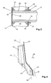
Fig. 2 , - Fig. 5
- eine schematische Schnittansicht entlang der Linie V-V in
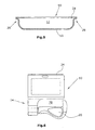
Fig. 2 mit geöffneter Entnahmeöffnung, und - Fig. 6
- eine schematische Vorderansicht der Display-Verpackung entsprechend
Fig. 2 mit aufgestecktem Fahrradgriff. - Die in bevorzugter Ausführungsform vollständig aus Pappe und biologisch abbaubaren Klebematerialien hergestellte Display-Verpackung weist einen Verpackungsbehälter 10 auf. Innerhalb des Verpackungsbehälters 10 kann ein nicht dargestellter, erster Fahrradgriff sowie Zubehör angeordnet werden. Bei dem Zubehör handelt es sich beispielsweise um Lenkerhörnchen, Lenkerstopfen, Befestigungsklemmen etc. Ferner kann in dem Verpackungsraum 12, der durch den Verpackungsbehälter 10 ausgebildet ist, die Montageanleitung angeordnet werden. Der Verpackungsbehälter 10 ist einstückig mit einem Verbindungsarm 14 ausgebildet. Sowohl der Verpackungsbehälter 10 als auch der Verbindungsarm 14 sind vorzugsweise aus Pappe als dreidimensionaler Formkörper ausgebildet und vorzugsweise beide hohl, wobei zwischen dem Hohlraum des Verbindungsarms 14 und dem Verpackungsraum 12 eine Trennwand vorgesehen sein kann. Mit dem Verbindungsarm 14 ist ein insbesondere als Papprohr ausgebildetes Aufnahmeelement 16 verbunden, wobei das Aufnahmeelement 16 vorzugsweise mit einem Endbereich 18 (
Fig. 4 ) des Verbindungsarms 14 verbunden ist. Auf das stabförmige Aufnahmeelement ist ein zweiter Fahrradgriff 20 (Fig. 6 ) aufsteckbar. - Eine Vorderseite 22 des Verpackungsbehälters 10 ist mit einem ebenfalls in bevorzugter Ausführungsform aus Pappe hergestellten Verschließelement 24 verschlossen. In der dargestellten Ausführungsform erstreckt sich das Verschließelement auch über eine Vorderseite 26 des Verbindungsarms 14, so dass eine in sich geschlossene Displayfläche 22, 26 ausgebildet ist. Das Verschließelement kann ein dreidimensional vorgeformtes Pappelement sein. Ebenso ist es möglich, dass das Verbindungselement eine entsprechende Flexibilität aufweist und durch Verkleben mit Rändern 28 (
Fig. 5 ) des Verpackungsbehälters fixiert wird. Ein entsprechendes Verkleben erfolgt auch im Bereich des Verbindungsarms. - Das stabförmige Aufnahmeelement 16 ragt in einen Hohlraum 30 (
Fig. 3 ) des Verbindungsarms 14. Hierzu weist eine innere, in Richtung des Aufnahmeelements 16 weisende Wand 32 des Verbindungsarms 14 eine Aufnahmeöffnung 34 auf. Der Durchmesser der Aufnahmeöffnung 34 entspricht dem Außendurchmesser des Aufnahmeelements 16. Das Aufnahmeelement 16 ist durch die Aufnahmeöffnung 34 so weit in den Hohlraum 30 hineingesteckt, dass eine erste Stirnfläche 36 des Aufnahmeelements 16 an einer Innenfläche 38 einer äußeren, vom Aufnahmeelement 16 abgewandten Seitenwand 40 des Verbindungsarms 14 anliegt. - Im dargestellten Ausführungsbeispiel erfolgt das Verbinden des Aufnahmeelements 16 über ein erstes Fixierelement 42 und ein zweites Fixierelement 44. Im dargestellten Ausführungsbeispiel handelt es sich bei den Fixierelementen 42, 44 um Verbindungswulste, die vorzugsweise aus einem Klebstoffschaum hergestellt sind, wobei es besonders bevorzugt ist, dass es sich um einen biologisch abbaubaren Klebstoff handelt. Durch die beiden Fixierelemente 42, 44 erfolgt jeweils ein Verbinden einer Außenseite 46 des stabförmigen Aufnahmeelements 16 mit einer Innenseite 48 der Wand 32 bzw. einer Innenseite 50 der Wand 40. Die Verbindungswulste 42, 44 können umlaufend ringförmig ausgebildet sein. Ggf. sind die Verbindungswulste jedoch nur teilringförmig.
- Ferner ist an einer Außenseite 60 der Wand 32 eine insbesondere ringförmige Hülse 62 angeordnet. Die Hülse 62 kann mit der Außenseite 60 der Wand 32 und/ oder der Außenseite 46 des Aufnahmeelements 16, insbesondere durch Verkleben, verbunden sein.
- Eine Mittelebene 52 (
Fig. 4 ) des Verpackungsbehälters 10 weist zu einer Mittelebene 54 des Verbindungsarms 14 einen Winkel α auf. Dieser ist größer 0°, insbesondere größer 30°, so dass, bezogen auf den Verpackungsbehälter 10, der Verbindungsarm nach vorne, d.h. in Richtung eines Pfeils 56 inFig. 4 weist. - Das Endelement 18 des Verbindungsarms ist sodann wieder geringer geneigt, wobei eine Mittelebene 58 des Endelements gegenüber der Mittelebene 52 des Verpackungsbehälters 10 einen Winkel aufweist, der kleiner als der Winkel α ist. Ggf. sind die beiden Ebenen 52, 58 zueinander parallel.
- Wie insbesondere an der Ausgestaltung des Verschließelements 24 in der Seitenansicht (
Fig. 4 ) ersichtlich ist, ist der Verbindungsarm vorzugsweise in Verbindung mit dem Verpackungsbehälter 10 in Seitenansicht S-förmig bzw. weist eine S-förmige Mittellinie auf. - Zur Entnahme des ersten Fahrradgriffs aus dem Verpackungsraum 12 kann das Verschließelement 24 über ein Öffnungselement 64, wie beispielsweise eine Reißlasche oder eine Perforation, geöffnet werden. Hierdurch entsteht eine Entnahmeöffnung 66 (
Fig. 5 ). Durch Öffnen der Entnahmeöffnung 66 erfolgt jedoch kein Zerstören der Klebverbindung im Randbereich 28 des Verpackungsbehälters 10, in dem dieser mit dem Verschließelement 24 verklebt ist. - Das insbesondere als Papprohr ausgebildete Aufnahmeelement 16 ist an seiner zweiten Stirnseite mit einem Verschlusselement 68, bei dem es sich insbesondere um einen aus Pappe hergestellten Deckel handelt, verschlossen. Das Verschlusselement 68 kann mit der Innenseite des Aufnahmeelements 16 durch Verkleben verbunden sein.
- Bei auf das Aufnahmeelement 16 aufgestecktem Fahrradgriff (
Fig. 6 ) entsteht zwischen dem zweiten Fahrradgriff 20 und dem Verpackungsbehälter 10 eine Greiföffnung 70. Es ist somit für den Kunden auf einfache Weise möglich, den Fahrradgriff 20 anzufassen und entsprechend eines Griffs, der auf einen Lenker montiert ist, zu ergreifen.
Claims (17)
- Display-Verpackung für Fahrradgriffe, mit
einem einen Verpackungsraum (12) ausbildenden Verpackungsbehälter (10) zur Aufnahme zumindest eines ersten Fahrradgriffs, und
einem mit dem Verpackungsbehälter (10) über einen Verbindungsarm (14) verbundenen, stabförmigen Aufnahmeelement (16), auf das ein zweiter Fahrradgriff (20) aufsteckbar ist,
dadurch gekennzeichnet, dass
der Verpackungsbehälter (10) mit dem Verbindungsarm (14) einstückig ausgebildet ist. - Display-Verpackung nach Anspruch 1, dadurch gekennzeichnet, dass der Verpackungsbehälter (10) und der Verbindungsarm (14) und/ oder das Aufnahmeelement (16) ausschließlich aus Pappe hergestellt ist.
- Display-Verpackung nach Anspruch 1 oder 2, gekennzeichnet durch ein eine Vorderseite (22) des Verpackungsbehälters (10) und/ oder eine Vorderseite (26) des Verbindungsarms (14) verschließendes, insbesondere aus Pappe hergestelltes Verschließelement (24).
- Display-Verpackung nach einem der Ansprüche 1 bis 3, dadurch gekennzeichnet, dass der Verpackungsbehälter (10) und der Verbindungsarm (14) ein gemeinsames, insbesondere eine geschlossene Displayfläche (22, 26) ausbildendes Verschließelement (24) aufweisen.
- Display-Verpackung nach einem der Ansprüche 1 bis 4, dadurch gekennzeichnet, dass der Verbindungsarm (14) gegenüber dem Verpackungsbehälter (10) in einem Neigungswinkel >0°, insbesondere >20° und besonders bevorzugt >30° angeordnet ist.
- Display-Verpackung nach Anspruch 5, dadurch gekennzeichnet, dass ein Endelement (18) des Verbindungsarms (14) eine gegenüber dem Verpackungsbehälter (10) geringeren Neigungswinkel als der Verbindungsarm (14) aufweist.
- Display-Verpackung nach einem der Ansprüche 1 bis 6, dadurch gekennzeichnet, dass der Verbindungsarm (14) eine im Wesentlichen S-förmige Mittellinie aufweist.
- Display-Verpackung nach einem der Ansprüche 1 bis 7, dadurch gekennzeichnet, dass der Verbindungsarm (14) hohl ausgebildet ist.
- Display-Verpackung nach einem der Ansprüche 1 bis 8, dadurch gekennzeichnet, dass das Aufnahmeelement (16) in dem Verbindungsarm (14) durch eine Aufnahmeöffnung (34) ragt.
- Display-Verpackung nach Anspruch 9, dadurch gekennzeichnet, dass eine erste Stirnfläche (36) des Aufnahmeelements (16) an einer Innenfläche (50) des Verbindungsarms (14) anliegt, insbesondere durch eine Klebverbindung fest mit der Innenfläche (50) verbunden ist.
- Display-Verpackung nach Anspruch 10, dadurch gekennzeichnet, dass die Verbindung durch ein das Aufnahmeelement (16) zumindest teilweise umgebendes, insbesondere als Verbindungswulst ausgebildetes erstes Fixierelement (42) erfolgt.
- Display-Verpackung nach einem der Ansprüche 9 bis 11, dadurch gekennzeichnet, dass an einer Innenseite (48) der die Aufnahmeöffnung (34) aufweisenden Wand (32) des Verbindungsarms (14) ein mit dem Aufnahmeelement (16) und/ oder der Innenseite (48) der Wand (32) verbundenes zweites Fixierelement (44) angeordnet ist, das vorzugsweise als Verbindungswulst ausgebildet ist.
- Display-Verpackung nach einem der Ansprüche 9 bis 12, dadurch gekennzeichnet, dass an einer Außenseite (60) der die Aufnahmeöffnung (34) aufweisenden Wand (32) des Verbindungsarms (14) eine das Aufnahmeelement (16) umgebende Hülse (32) angeordnet ist.
- Display-Verpackung nach einem der Ansprüche 3 bis 13, dadurch gekennzeichnet, dass das Verschließelement (24) im Bereich der Vorderseite (22) des Verpackungsbehälters (10) ein Öffenelement (64) zur Ausbildung einer Entnahmeöffnung (66) aufweist.
- Display-Verpackung nach einem der Ansprüche 1 bis 14, dadurch gekennzeichnet, dass eine zweite, vom Verbindungsarm (14) weg weisende Stirnseite des Aufnahmeelements (16) mit einem insbesondere aus Pappe hergestellten Verschließelement (68) verschlossen ist.
- Display-Verpackung nach einem der Ansprüche 1 bis 15, dadurch gekennzeichnet, dass auch bei aufgestecktem zweitem Fahrradgriff (20) zwischen dem Aufnahmeelement (16) bzw. dem Fahrradgriff (20) und dem Verpackungsbehälter (10) eine Greiföffnung (70) ausgebildet ist.
- Display-Verpackung nach einem der Ansprüche 3 bis 16, dadurch gekennzeichnet, dass das Aufnahmeelement (16) zu der Vorderseite des Verpackungsbehälters (10) versetzt, insbesondere vollständig außerhalb einer durch die Vorderseite (22) gebildeten Ebene angeordnet ist.
Applications Claiming Priority (1)
| Application Number | Priority Date | Filing Date | Title |
|---|---|---|---|
| DE202008011712U DE202008011712U1 (de) | 2008-09-03 | 2008-09-03 | Display-Verpackung für Fahrradgriffe |
Publications (2)
| Publication Number | Publication Date |
|---|---|
| EP2161215A1 EP2161215A1 (de) | 2010-03-10 |
| EP2161215B1 true EP2161215B1 (de) | 2011-03-09 |
Family
ID=41346129
Family Applications (1)
| Application Number | Title | Priority Date | Filing Date |
|---|---|---|---|
| EP09167777A Active EP2161215B1 (de) | 2008-09-03 | 2009-08-13 | Display-Verpackung für Fahrradgriffe |
Country Status (5)
| Country | Link |
|---|---|
| US (1) | US20100051676A1 (de) |
| EP (1) | EP2161215B1 (de) |
| AT (1) | ATE501058T1 (de) |
| DE (2) | DE202008011712U1 (de) |
| TW (1) | TW201016561A (de) |
Families Citing this family (3)
| Publication number | Priority date | Publication date | Assignee | Title |
|---|---|---|---|---|
| DE202010011986U1 (de) | 2010-08-30 | 2011-12-06 | Rti Sports Vertrieb Von Sportartikeln Gmbh | Präsentiervorrichtung für einen Fahrradgriff |
| DE202010012048U1 (de) | 2010-08-31 | 2011-12-02 | Rti Sports Vertrieb Von Sportartikeln Gmbh | Verpackung für Fahrradpedale |
| US8690400B2 (en) | 2011-06-29 | 2014-04-08 | Target Brands, Inc. | Holding structure for light socket |
Family Cites Families (9)
| Publication number | Priority date | Publication date | Assignee | Title |
|---|---|---|---|---|
| US3529716A (en) * | 1967-10-12 | 1970-09-22 | Oconnell Paula A | Clip for packaging of,for example,hair curlers |
| US4359161A (en) * | 1980-02-07 | 1982-11-16 | Leonard Sinoff | Display package for a combination fishing rod and reel assembly |
| US4493416A (en) * | 1983-06-20 | 1985-01-15 | Kenneth Steinman | Tamper proof reel package for a fishing rod |
| US4946034A (en) * | 1989-04-27 | 1990-08-07 | Daiwa Seiko, Inc. | Protective case and manual for fishing tackle |
| US5279417A (en) * | 1992-07-14 | 1994-01-18 | Fiskars Oy Ab | Package for hand tools |
| US6415933B1 (en) * | 1999-11-05 | 2002-07-09 | Jui-Chien Kao | Socket suspension rack |
| US6276529B1 (en) * | 2000-02-16 | 2001-08-21 | The Gillette Company | Packaging unit for articles with convenient opening strip |
| US20050194281A1 (en) * | 2004-02-11 | 2005-09-08 | Chris Richards | Packaging for product display |
| DE202004009963U1 (de) * | 2004-06-24 | 2005-10-27 | Rti Sports Vertrieb Von Sportartikeln Gmbh | Display für Fahrradgriffe |
-
2008
- 2008-09-03 DE DE202008011712U patent/DE202008011712U1/de not_active Expired - Lifetime
-
2009
- 2009-08-13 AT AT09167777T patent/ATE501058T1/de active
- 2009-08-13 EP EP09167777A patent/EP2161215B1/de active Active
- 2009-08-13 DE DE502009000438T patent/DE502009000438D1/de active Active
- 2009-08-28 TW TW098129120A patent/TW201016561A/zh unknown
- 2009-09-01 US US12/552,020 patent/US20100051676A1/en not_active Abandoned
Also Published As
| Publication number | Publication date |
|---|---|
| EP2161215A1 (de) | 2010-03-10 |
| US20100051676A1 (en) | 2010-03-04 |
| DE502009000438D1 (de) | 2011-04-21 |
| ATE501058T1 (de) | 2011-03-15 |
| DE202008011712U1 (de) | 2010-01-28 |
| TW201016561A (en) | 2010-05-01 |
Similar Documents
| Publication | Publication Date | Title |
|---|---|---|
| DE60219214T2 (de) | Kindersichere verpackung mit verschiebbarem einsatzabschnitt | |
| EP2183738A1 (de) | Displayelement zum anbringen von werbung am griff eines einkaufswagens | |
| DE60106392T2 (de) | Abgabevorrichtung mit greifereinrichtung | |
| EP2161215A1 (de) | Display-Verpackung für Fahrradgriffe | |
| WO1997008058A1 (de) | Verpackungsbehälter | |
| EP2423129B1 (de) | Verpackung für Fahrradpedale | |
| EP1308579B1 (de) | Werkzeug zur Nachbearbeitung von Fugen aus dauerelastischer Fugenmasse sowie Anordnung mit Werkzeug | |
| EP3083428B1 (de) | Klappdeckelverschluss für ein behältnis | |
| EP1609736B1 (de) | Schauverpackung für Fahrradgriffe | |
| EP2989928B1 (de) | Bewegbares möbelteil mit einer seitenabdeckung und einem blendenprofil sowie einer vorrichtung zur befestigung der beiden | |
| EP0731036B1 (de) | Deckel | |
| WO2006136592A1 (de) | Im kunststoffspritzverfahren hergestelltes behältnis sowie zum hinterspritzen durch kunststoff vorgesehenes kunststofffolien-etikett | |
| EP0553639B1 (de) | Kraftfahrzeugkarosserie | |
| DE3426297C2 (de) | ||
| AT520530B1 (de) | Tablettenspender | |
| DE10308825B4 (de) | Schließvorrichtung an einem Halter oder einer Verpackung | |
| DE9415745U1 (de) | Halterung insbesondere für Flüssigseifespender | |
| EP1467902A2 (de) | Griff für einen transportwagen | |
| DE19941187C2 (de) | Befestigungsvorrichtung zur Befestigung eines Papierblocks | |
| DE19605353A1 (de) | Vorrichtung zur Montage eines elektronischen Bauteils in einen Schlüsselgriff | |
| DE202005002860U1 (de) | Quaderförmige Verpackung | |
| DE4431243A1 (de) | Kunststoffklappe, insbesondere Kofferraumklappe an einer Busaußenwand | |
| EP1083095B1 (de) | Vorrichtung zur Versteifung eines Dachhimmels eines Kraftfahrzeugs | |
| DE2051282C3 (de) | Muschelgriff | |
| DE29916228U1 (de) | Verkaufsverpackung für Handwerkzeuge |
Legal Events
| Date | Code | Title | Description |
|---|---|---|---|
| PUAI | Public reference made under article 153(3) epc to a published international application that has entered the european phase |
Free format text: ORIGINAL CODE: 0009012 |
|
| 17P | Request for examination filed |
Effective date: 20091217 |
|
| AK | Designated contracting states |
Kind code of ref document: A1 Designated state(s): AT BE BG CH CY CZ DE DK EE ES FI FR GB GR HR HU IE IS IT LI LT LU LV MC MK MT NL NO PL PT RO SE SI SK SM TR |
|
| AX | Request for extension of the european patent |
Extension state: AL BA RS |
|
| RIC1 | Information provided on ipc code assigned before grant |
Ipc: B65D 25/10 20060101ALI20100730BHEP Ipc: B65D 75/36 20060101ALI20100730BHEP Ipc: B62K 21/26 20060101ALI20100730BHEP Ipc: B65D 73/00 20060101AFI20100730BHEP |
|
| GRAP | Despatch of communication of intention to grant a patent |
Free format text: ORIGINAL CODE: EPIDOSNIGR1 |
|
| GRAS | Grant fee paid |
Free format text: ORIGINAL CODE: EPIDOSNIGR3 |
|
| GRAA | (expected) grant |
Free format text: ORIGINAL CODE: 0009210 |
|
| AK | Designated contracting states |
Kind code of ref document: B1 Designated state(s): AT BE BG CH CY CZ DE DK EE ES FI FR GB GR HR HU IE IS IT LI LT LU LV MC MK MT NL NO PL PT RO SE SI SK SM TR |
|
| REG | Reference to a national code |
Ref country code: GB Ref legal event code: FG4D Free format text: NOT ENGLISH |
|
| REG | Reference to a national code |
Ref country code: CH Ref legal event code: EP |
|
| REG | Reference to a national code |
Ref country code: IE Ref legal event code: FG4D Free format text: LANGUAGE OF EP DOCUMENT: GERMAN |
|
| REF | Corresponds to: |
Ref document number: 502009000438 Country of ref document: DE Date of ref document: 20110421 Kind code of ref document: P |
|
| REG | Reference to a national code |
Ref country code: DE Ref legal event code: R096 Ref document number: 502009000438 Country of ref document: DE Effective date: 20110421 |
|
| RAP2 | Party data changed (patent owner data changed or rights of a patent transferred) |
Owner name: RTI SPORTS VERTRIEB VON SPORTARTIKELN GMBH |
|
| REG | Reference to a national code |
Ref country code: NL Ref legal event code: VDEP Effective date: 20110309 |
|
| PG25 | Lapsed in a contracting state [announced via postgrant information from national office to epo] |
Ref country code: LV Free format text: LAPSE BECAUSE OF FAILURE TO SUBMIT A TRANSLATION OF THE DESCRIPTION OR TO PAY THE FEE WITHIN THE PRESCRIBED TIME-LIMIT Effective date: 20110309 Ref country code: ES Free format text: LAPSE BECAUSE OF FAILURE TO SUBMIT A TRANSLATION OF THE DESCRIPTION OR TO PAY THE FEE WITHIN THE PRESCRIBED TIME-LIMIT Effective date: 20110620 Ref country code: SE Free format text: LAPSE BECAUSE OF FAILURE TO SUBMIT A TRANSLATION OF THE DESCRIPTION OR TO PAY THE FEE WITHIN THE PRESCRIBED TIME-LIMIT Effective date: 20110309 Ref country code: LT Free format text: LAPSE BECAUSE OF FAILURE TO SUBMIT A TRANSLATION OF THE DESCRIPTION OR TO PAY THE FEE WITHIN THE PRESCRIBED TIME-LIMIT Effective date: 20110309 Ref country code: GR Free format text: LAPSE BECAUSE OF FAILURE TO SUBMIT A TRANSLATION OF THE DESCRIPTION OR TO PAY THE FEE WITHIN THE PRESCRIBED TIME-LIMIT Effective date: 20110610 Ref country code: HR Free format text: LAPSE BECAUSE OF FAILURE TO SUBMIT A TRANSLATION OF THE DESCRIPTION OR TO PAY THE FEE WITHIN THE PRESCRIBED TIME-LIMIT Effective date: 20110309 Ref country code: NO Free format text: LAPSE BECAUSE OF FAILURE TO SUBMIT A TRANSLATION OF THE DESCRIPTION OR TO PAY THE FEE WITHIN THE PRESCRIBED TIME-LIMIT Effective date: 20110609 |
|
| LTIE | Lt: invalidation of european patent or patent extension |
Effective date: 20110309 |
|
| PG25 | Lapsed in a contracting state [announced via postgrant information from national office to epo] |
Ref country code: SI Free format text: LAPSE BECAUSE OF FAILURE TO SUBMIT A TRANSLATION OF THE DESCRIPTION OR TO PAY THE FEE WITHIN THE PRESCRIBED TIME-LIMIT Effective date: 20110309 Ref country code: NL Free format text: LAPSE BECAUSE OF FAILURE TO SUBMIT A TRANSLATION OF THE DESCRIPTION OR TO PAY THE FEE WITHIN THE PRESCRIBED TIME-LIMIT Effective date: 20110309 Ref country code: FI Free format text: LAPSE BECAUSE OF FAILURE TO SUBMIT A TRANSLATION OF THE DESCRIPTION OR TO PAY THE FEE WITHIN THE PRESCRIBED TIME-LIMIT Effective date: 20110309 Ref country code: CY Free format text: LAPSE BECAUSE OF FAILURE TO SUBMIT A TRANSLATION OF THE DESCRIPTION OR TO PAY THE FEE WITHIN THE PRESCRIBED TIME-LIMIT Effective date: 20110309 Ref country code: BG Free format text: LAPSE BECAUSE OF FAILURE TO SUBMIT A TRANSLATION OF THE DESCRIPTION OR TO PAY THE FEE WITHIN THE PRESCRIBED TIME-LIMIT Effective date: 20110609 |
|
| RAP2 | Party data changed (patent owner data changed or rights of a patent transferred) |
Owner name: RTI SPORTS VERTRIEB VON SPORTARTIKELN GMBH |
|
| REG | Reference to a national code |
Ref country code: IE Ref legal event code: FD4D |
|
| PG25 | Lapsed in a contracting state [announced via postgrant information from national office to epo] |
Ref country code: PT Free format text: LAPSE BECAUSE OF FAILURE TO SUBMIT A TRANSLATION OF THE DESCRIPTION OR TO PAY THE FEE WITHIN THE PRESCRIBED TIME-LIMIT Effective date: 20110711 Ref country code: IE Free format text: LAPSE BECAUSE OF FAILURE TO SUBMIT A TRANSLATION OF THE DESCRIPTION OR TO PAY THE FEE WITHIN THE PRESCRIBED TIME-LIMIT Effective date: 20110309 Ref country code: EE Free format text: LAPSE BECAUSE OF FAILURE TO SUBMIT A TRANSLATION OF THE DESCRIPTION OR TO PAY THE FEE WITHIN THE PRESCRIBED TIME-LIMIT Effective date: 20110309 |
|
| PG25 | Lapsed in a contracting state [announced via postgrant information from national office to epo] |
Ref country code: SK Free format text: LAPSE BECAUSE OF FAILURE TO SUBMIT A TRANSLATION OF THE DESCRIPTION OR TO PAY THE FEE WITHIN THE PRESCRIBED TIME-LIMIT Effective date: 20110309 Ref country code: CZ Free format text: LAPSE BECAUSE OF FAILURE TO SUBMIT A TRANSLATION OF THE DESCRIPTION OR TO PAY THE FEE WITHIN THE PRESCRIBED TIME-LIMIT Effective date: 20110309 Ref country code: IS Free format text: LAPSE BECAUSE OF FAILURE TO SUBMIT A TRANSLATION OF THE DESCRIPTION OR TO PAY THE FEE WITHIN THE PRESCRIBED TIME-LIMIT Effective date: 20110709 Ref country code: RO Free format text: LAPSE BECAUSE OF FAILURE TO SUBMIT A TRANSLATION OF THE DESCRIPTION OR TO PAY THE FEE WITHIN THE PRESCRIBED TIME-LIMIT Effective date: 20110309 |
|
| REG | Reference to a national code |
Ref country code: DE Ref legal event code: R081 Ref document number: 502009000438 Country of ref document: DE Owner name: RTI SPORTS, VERTRIEB VON SPORTARTIKELN GMBH, DE Free format text: FORMER OWNER: RTI SPORTS VERTRIEB VON SPORTARTIKELN GMBH, 56220 URMITZ, DE Effective date: 20111107 |
|
| PG25 | Lapsed in a contracting state [announced via postgrant information from national office to epo] |
Ref country code: MT Free format text: LAPSE BECAUSE OF FAILURE TO SUBMIT A TRANSLATION OF THE DESCRIPTION OR TO PAY THE FEE WITHIN THE PRESCRIBED TIME-LIMIT Effective date: 20110309 |
|
| PLBE | No opposition filed within time limit |
Free format text: ORIGINAL CODE: 0009261 |
|
| STAA | Information on the status of an ep patent application or granted ep patent |
Free format text: STATUS: NO OPPOSITION FILED WITHIN TIME LIMIT |
|
| 26N | No opposition filed |
Effective date: 20111212 |
|
| BERE | Be: lapsed |
Owner name: RTI SPORTS VERTRIEB VON SPORTARTIKELN G.M.B.H. Effective date: 20110831 |
|
| PG25 | Lapsed in a contracting state [announced via postgrant information from national office to epo] |
Ref country code: PL Free format text: LAPSE BECAUSE OF FAILURE TO SUBMIT A TRANSLATION OF THE DESCRIPTION OR TO PAY THE FEE WITHIN THE PRESCRIBED TIME-LIMIT Effective date: 20110309 |
|
| PG25 | Lapsed in a contracting state [announced via postgrant information from national office to epo] |
Ref country code: MC Free format text: LAPSE BECAUSE OF NON-PAYMENT OF DUE FEES Effective date: 20110831 |
|
| REG | Reference to a national code |
Ref country code: DE Ref legal event code: R097 Ref document number: 502009000438 Country of ref document: DE Effective date: 20111212 |
|
| REG | Reference to a national code |
Ref country code: FR Ref legal event code: ST Effective date: 20120430 |
|
| PG25 | Lapsed in a contracting state [announced via postgrant information from national office to epo] |
Ref country code: IT Free format text: LAPSE BECAUSE OF FAILURE TO SUBMIT A TRANSLATION OF THE DESCRIPTION OR TO PAY THE FEE WITHIN THE PRESCRIBED TIME-LIMIT Effective date: 20110309 Ref country code: BE Free format text: LAPSE BECAUSE OF NON-PAYMENT OF DUE FEES Effective date: 20110831 |
|
| REG | Reference to a national code |
Ref country code: DE Ref legal event code: R119 Ref document number: 502009000438 Country of ref document: DE Effective date: 20120301 |
|
| PG25 | Lapsed in a contracting state [announced via postgrant information from national office to epo] |
Ref country code: FR Free format text: LAPSE BECAUSE OF NON-PAYMENT OF DUE FEES Effective date: 20110831 |
|
| PG25 | Lapsed in a contracting state [announced via postgrant information from national office to epo] |
Ref country code: MK Free format text: LAPSE BECAUSE OF FAILURE TO SUBMIT A TRANSLATION OF THE DESCRIPTION OR TO PAY THE FEE WITHIN THE PRESCRIBED TIME-LIMIT Effective date: 20110309 |
|
| PG25 | Lapsed in a contracting state [announced via postgrant information from national office to epo] |
Ref country code: SM Free format text: LAPSE BECAUSE OF FAILURE TO SUBMIT A TRANSLATION OF THE DESCRIPTION OR TO PAY THE FEE WITHIN THE PRESCRIBED TIME-LIMIT Effective date: 20110309 |
|
| PG25 | Lapsed in a contracting state [announced via postgrant information from national office to epo] |
Ref country code: LU Free format text: LAPSE BECAUSE OF NON-PAYMENT OF DUE FEES Effective date: 20110813 |
|
| PG25 | Lapsed in a contracting state [announced via postgrant information from national office to epo] |
Ref country code: DE Free format text: LAPSE BECAUSE OF NON-PAYMENT OF DUE FEES Effective date: 20120301 |
|
| PG25 | Lapsed in a contracting state [announced via postgrant information from national office to epo] |
Ref country code: TR Free format text: LAPSE BECAUSE OF FAILURE TO SUBMIT A TRANSLATION OF THE DESCRIPTION OR TO PAY THE FEE WITHIN THE PRESCRIBED TIME-LIMIT Effective date: 20110309 |
|
| PG25 | Lapsed in a contracting state [announced via postgrant information from national office to epo] |
Ref country code: HU Free format text: LAPSE BECAUSE OF FAILURE TO SUBMIT A TRANSLATION OF THE DESCRIPTION OR TO PAY THE FEE WITHIN THE PRESCRIBED TIME-LIMIT Effective date: 20110309 |
|
| REG | Reference to a national code |
Ref country code: CH Ref legal event code: PL |
|
| GBPC | Gb: european patent ceased through non-payment of renewal fee |
Effective date: 20130813 |
|
| PG25 | Lapsed in a contracting state [announced via postgrant information from national office to epo] |
Ref country code: CH Free format text: LAPSE BECAUSE OF NON-PAYMENT OF DUE FEES Effective date: 20130831 Ref country code: LI Free format text: LAPSE BECAUSE OF NON-PAYMENT OF DUE FEES Effective date: 20130831 |
|
| PG25 | Lapsed in a contracting state [announced via postgrant information from national office to epo] |
Ref country code: GB Free format text: LAPSE BECAUSE OF NON-PAYMENT OF DUE FEES Effective date: 20130813 |
|
| REG | Reference to a national code |
Ref country code: AT Ref legal event code: MM01 Ref document number: 501058 Country of ref document: AT Kind code of ref document: T Effective date: 20140813 |
|
| PG25 | Lapsed in a contracting state [announced via postgrant information from national office to epo] |
Ref country code: AT Free format text: LAPSE BECAUSE OF NON-PAYMENT OF DUE FEES Effective date: 20140813 |