EP2160534B1 - Ventilkopplung - Google Patents
Ventilkopplung Download PDFInfo
- Publication number
- EP2160534B1 EP2160534B1 EP08773480.2A EP08773480A EP2160534B1 EP 2160534 B1 EP2160534 B1 EP 2160534B1 EP 08773480 A EP08773480 A EP 08773480A EP 2160534 B1 EP2160534 B1 EP 2160534B1
- Authority
- EP
- European Patent Office
- Prior art keywords
- valve
- dispensing
- receiving part
- dome
- electric
- Prior art date
- Legal status (The legal status is an assumption and is not a legal conclusion. Google has not performed a legal analysis and makes no representation as to the accuracy of the status listed.)
- Not-in-force
Links
- 230000008878 coupling Effects 0.000 title claims description 52
- 238000010168 coupling process Methods 0.000 title claims description 52
- 238000005859 coupling reaction Methods 0.000 title claims description 52
- 239000013013 elastic material Substances 0.000 claims description 19
- 239000007788 liquid Substances 0.000 claims description 16
- 238000007789 sealing Methods 0.000 claims description 11
- 239000000463 material Substances 0.000 claims description 10
- 239000011343 solid material Substances 0.000 claims description 3
- 230000000295 complement effect Effects 0.000 claims description 2
- 230000002787 reinforcement Effects 0.000 claims description 2
- 230000005489 elastic deformation Effects 0.000 claims 2
- 239000003795 chemical substances by application Substances 0.000 description 22
- 235000011837 pasties Nutrition 0.000 description 7
- 238000006073 displacement reaction Methods 0.000 description 5
- 238000000465 moulding Methods 0.000 description 5
- 238000000926 separation method Methods 0.000 description 5
- 230000003014 reinforcing effect Effects 0.000 description 4
- 239000012530 fluid Substances 0.000 description 3
- 238000007373 indentation Methods 0.000 description 3
- 229910000831 Steel Inorganic materials 0.000 description 2
- 239000000551 dentifrice Substances 0.000 description 2
- 230000000694 effects Effects 0.000 description 2
- 230000009969 flowable effect Effects 0.000 description 2
- 239000002184 metal Substances 0.000 description 2
- 230000000717 retained effect Effects 0.000 description 2
- 239000010959 steel Substances 0.000 description 2
- 230000035882 stress Effects 0.000 description 2
- 239000000126 substance Substances 0.000 description 2
- 238000004073 vulcanization Methods 0.000 description 2
- 206010040880 Skin irritation Diseases 0.000 description 1
- 238000004026 adhesive bonding Methods 0.000 description 1
- 230000003679 aging effect Effects 0.000 description 1
- 230000000903 blocking effect Effects 0.000 description 1
- 238000004140 cleaning Methods 0.000 description 1
- 230000006835 compression Effects 0.000 description 1
- 238000007906 compression Methods 0.000 description 1
- 230000001010 compromised effect Effects 0.000 description 1
- 238000011109 contamination Methods 0.000 description 1
- 238000001035 drying Methods 0.000 description 1
- 238000009434 installation Methods 0.000 description 1
- 239000006210 lotion Substances 0.000 description 1
- 230000036316 preload Effects 0.000 description 1
- 238000007493 shaping process Methods 0.000 description 1
- 230000036556 skin irritation Effects 0.000 description 1
- 231100000475 skin irritation Toxicity 0.000 description 1
- 239000000606 toothpaste Substances 0.000 description 1
- 229940034610 toothpaste Drugs 0.000 description 1
Images



Classifications
-
- F—MECHANICAL ENGINEERING; LIGHTING; HEATING; WEAPONS; BLASTING
- F16—ENGINEERING ELEMENTS AND UNITS; GENERAL MEASURES FOR PRODUCING AND MAINTAINING EFFECTIVE FUNCTIONING OF MACHINES OR INSTALLATIONS; THERMAL INSULATION IN GENERAL
- F16K—VALVES; TAPS; COCKS; ACTUATING-FLOATS; DEVICES FOR VENTING OR AERATING
- F16K15/00—Check valves
- F16K15/14—Check valves with flexible valve members
- F16K15/144—Check valves with flexible valve members the closure elements being fixed along all or a part of their periphery
- F16K15/147—Check valves with flexible valve members the closure elements being fixed along all or a part of their periphery the closure elements having specially formed slits or being of an elongated easily collapsible form
-
- A—HUMAN NECESSITIES
- A46—BRUSHWARE
- A46B—BRUSHES
- A46B11/00—Brushes with reservoir or other means for applying substances, e.g. paints, pastes, water
- A46B11/001—Brushes with reservoir or other means for applying substances, e.g. paints, pastes, water with integral reservoirs
- A46B11/002—Brushes with reservoir or other means for applying substances, e.g. paints, pastes, water with integral reservoirs pressurised at moment of use manually or by powered means
-
- A—HUMAN NECESSITIES
- A46—BRUSHWARE
- A46B—BRUSHES
- A46B11/00—Brushes with reservoir or other means for applying substances, e.g. paints, pastes, water
- A46B11/0072—Details
- A46B11/0079—Arrangements for preventing undesired leakage or dispensing
-
- A—HUMAN NECESSITIES
- A46—BRUSHWARE
- A46B—BRUSHES
- A46B7/00—Bristle carriers arranged in the brush body
- A46B7/04—Bristle carriers arranged in the brush body interchangeably removable bristle carriers
-
- A—HUMAN NECESSITIES
- A61—MEDICAL OR VETERINARY SCIENCE; HYGIENE
- A61C—DENTISTRY; APPARATUS OR METHODS FOR ORAL OR DENTAL HYGIENE
- A61C17/00—Devices for cleaning, polishing, rinsing or drying teeth, teeth cavities or prostheses; Saliva removers; Dental appliances for receiving spittle
- A61C17/16—Power-driven cleaning or polishing devices
- A61C17/22—Power-driven cleaning or polishing devices with brushes, cushions, cups, or the like
- A61C17/225—Handles or details thereof
- A61C17/227—Handles or details thereof with reservoirs, e.g. for toothpaste
-
- F—MECHANICAL ENGINEERING; LIGHTING; HEATING; WEAPONS; BLASTING
- F16—ENGINEERING ELEMENTS AND UNITS; GENERAL MEASURES FOR PRODUCING AND MAINTAINING EFFECTIVE FUNCTIONING OF MACHINES OR INSTALLATIONS; THERMAL INSULATION IN GENERAL
- F16L—PIPES; JOINTS OR FITTINGS FOR PIPES; SUPPORTS FOR PIPES, CABLES OR PROTECTIVE TUBING; MEANS FOR THERMAL INSULATION IN GENERAL
- F16L37/00—Couplings of the quick-acting type
- F16L37/28—Couplings of the quick-acting type with fluid cut-off means
- F16L37/30—Couplings of the quick-acting type with fluid cut-off means with fluid cut-off means in each of two pipe-end fittings
-
- A—HUMAN NECESSITIES
- A46—BRUSHWARE
- A46B—BRUSHES
- A46B2200/00—Brushes characterized by their functions, uses or applications
- A46B2200/10—For human or animal care
- A46B2200/1066—Toothbrush for cleaning the teeth or dentures
Definitions
- the invention relates to an electric shaver or an electric oral care device, for example an electric toothbrush having a liquid-tight separation point between a handpiece and an additional part connectable therewith, with a valve coupling with a dispensing part and a receiving part for transferring a liquid or pasty agent.
- a corresponding valve coupling is for example from the DE 19704920 A1 known.
- the invention is based on the object to provide an electric shaver or an electric oral care device with an improved valve coupling, in which the function of the valve coupling is not compromised.
- the dispensing part is designed finger-like and hollow, that at least one tip of the dispensing part consists of an elastic material and having a valve slot, that the receiving part has a dome with a dome with a valve slot and consists of an elastic material , And that in the coupling state, an outer sides of the tip of the dispensing part and an inside of the tip of the receiving part non-positively and / or positively abut each other, whereby a cavity is avoided, in which residues of a flowable agent on the dispensing part and the receiving part accumulate, harden, dry or can clump, and thus a safe function of the valve coupling is ensured.
- the tip of the dispensing part is formed, for example, by a finger-like and hollow ausgestaltetes, one-piece molded part, which is covered below the tip of a rigid sleeve, whereby on the one hand the dispensing part receives a mechanical stability and on the other hand, the region of the dome is retained form-elastic.
- the receiving part is preferably at two opposite outer sides provided transversely to the longitudinal line of the second valve slot in each case with a Verspannrippe, whereby in terms of the valve function (closing function) fatigue effects of the material are compensated.
- On the receiving part can be integrally formed a flange, which is stiffened for ease of assembly of a support ring. For liquid-tight fastening of the receiving part may be formed on the flange, a sealing ring.
- the dispensing part is finger-like and hollow, that a tip of the dispensing part consists of an elastic material and has a valve slot, that the receiving part has a concave tip with a valve slot and consists of an elastic material that Receiving part is formed axially resilient, and that in the coupling state an outer side of the tip of the dispensing part and an outer side of the concave tip of the receiving part non-positively and / or positively abut each other, whereby a cavity is avoided, in which remains of the agent at the dispensing part and the Accumulate receiving part, harden, dry or clump, and thus a safe function of the valve coupling is ensured.
- the tip of the dispensing part is preferably formed by a finger-like and hollow ausgestaltetes, one-piece molded part, which is covered below the tip of a rigid sleeve, whereby on the one hand, the dispensing part receives a mechanical stability and on the other hand, the region of the dome is retained form-elastic.
- the receiving part has an axially resilient zone, which is formed by a rotationally symmetrical constriction.
- the dispensing part has a hollow needle with a dome that the hollow needle has a transverse bore below the dome, which is enveloped by a rubber sleeve, that the receiving part has a component made of an elastic material and is provided with a slot , And that in the coupling state, the hollow needle is inserted with the transverse bore through the slot and the rubber sleeve is reversibly withdrawn by the device so that the transverse bore is released, whereby a cavity is avoided, in which remains of the agent at the dispensing part and accumulate the receiving part, harden, dry or clump, and thereby a safe function of the valve coupling is ensured.
- the rubber sheath preferably has at the free end a reinforcing ring of rigid material which serves as a stop surface for axially displacing the rubber sheath, the receiving part having a support ring of rigid material corresponding to the reinforcing ring for axial displacement.
- the hollow needle is preferably enveloped by the rubber sleeve with a clearance, whereby the axial displacement of the rubber sleeve is facilitated on the hollow needle.
- the rubber sheath preferably has an inner sealing ring, which closes the transverse bore of the hollow needle to the outside in the decoupled state, whereby outside the hollow needle or the transverse bore no residues of the agent form, accumulate and harden or could clump.
- the valve coupling is arranged in the electric shaver or the electric oral care device, for example in an electric toothbrush, as a separation point between a handpiece and an additional part connectable therewith.
- Fig. 1 shows a sectional side view of a self-closing valve coupling 1.1 with a dispensing part 2.1 and a receiving part 3.1 almost in an end position of a coupled state for transferring a liquid or pasty agent 35.
- the dispensing part 2.1 is finger-like and hollow configured, with at least one tip 5.1 of the dispensing part 2.1 consists of an elastic material 37 and a valve slot 6.1 of a first slit valve 4.1 as a dispensing valve 101 (FIG. Fig. 2 ) having.
- the thimble-like receiving part 3.1 has an indentation 7 with a dome 5.2 with a valve slit 6.2 of a second slit valve 4.2 as a receiving valve 102 (FIG. Fig.
- the arrow 34 indicates the flow direction (inlet) of the means 35 in the discharge part 2.1;
- the arrow 38 shows the flow direction (outlet) of the means 35 from the receiving part 3.1, for example, in a brush attachment part 33 after Fig. 4 ,
- Fig. 2 shows in a sectional side view of the dispensing part 2.1, which consists of a finger-like and hollow configured, one-piece molding 15 made of elastic material 37 and a rigid sleeve 16 made of solid material - preferably made of stainless metal - with the molding 15 for stiffening and for fixed attachment the dispensing part 2.1 is firmly connected to the sleeve 16 below the dome 5.1, preferably by vulcanization.
- the dispensing part 2.1 is characterized so that only the area of the dome 5.1 is form-elastic with the valve slot 6.1 and can thus conform to the inside 9 of the receiving part 3.1.
- the dome 5.1 of the elastic molded part 15 is curved convexly outwards, so that from the inside pending pressure of the means 35, the dome 5.1 expands outwards and thus the valve slot 6.1 and thus the slit valve 4.1 opens.
- Fig. 3 shows in a sectional side view of the receiving part 3.1.
- the receiving part 3.1 is provided in the initial region of the indentation 7 with a radially encircling flange 21 and with a rigid support ring 22 which is fixedly connected to the bottle 21.
- An integrally formed on the flange 21 sealing ring 36 is used for liquid-tight mounting of the receiving part 3.1, wherein the rigid support ring 22 stabilizes the flange 21 as an assembly aid.
- the receiving part 3.1 can, for example, in a replaceable part, in particular a brush attachment 33 ( Fig. 4 ) for an electric toothbrush, installed.
- FIGS. 2 and 3 taken together, the valve coupling 1.1 before or after a coupling of the dispensing part 2.1 with the receiving part 3.1.
- Fig. 4 shows the dispensing part 2.1 can be arranged at the outlet of the liquid channel of a handpiece 32 of an electric toothbrush and the receiving part 3.1 at the entrance of a liquid channel in the brush attachment 33.
- the tip 5.1 of the dispensing part 2.1 is provided with a valve slot 6.1 and the dome 5.2 of the receiving part 3.1 with a valve slot 6.2.
- the slit valves 4.1, 4.2 seal in one direction like a check valve.
- the receiving part 3.1 in the brush attachment 33 also has the shape of a dome 5.2 with a valve slot 6.2 for the passage of the agent 35.
- This dome 5.2 has such an inner diameter that the dome 5.1 of the first slit valve 4.1 fits complementarily exactly.
- the slit valve 4.1 is opened by the pressure applied from the inside of the means 35; the slit valve 4.2 by the pressure exerted by the slit valve 4.1 on the slit valve 4.2 after the nested. After separating the valve coupling 1.1, both slit valves 4.1, 4.2 close by the residual stress of the material 37th
- Fig. 4 shows in a partially sectioned side view of the valve coupling 1.1 according to the Fig. 1 to 3 in an electric toothbrush 31 with a handpiece 32 and a detachable brush attachment 33.
- a reservoir for the means 35 with a pump and a fluid channel 51 to the dispensing part 2.1 is arranged out, being provided as a means 35, for example, a dentifrice, which can be transmitted via the valve coupling 1.1 and a liquid channel 52 in the brush attachment 33.
- the pump provides the required pressure build-up for transferring or conveying the agent 35 via the valve coupling into the brush attachment 33.
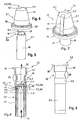
- Fig. 5 shows in a perspective side view of the dispensing part 2.1 after Fig. 1
- Fig. 6 shows in a perspective side view of the receiving part 3.1 after Fig. 3
- Fig. 5 shows in a perspective side view of the dispensing part 2.1 after Fig. 1
- Fig. 6 shows in a perspective side view of the receiving part 3.1 after Fig. 3
- Fig. 7 shows in a perspective side view the valve coupling after Fig. 1 , wherein the receiving part 3.1 additionally on two opposite outer sides 17, 18 transversely to the longitudinal line of the second valve slot 6.2 each have a Veritatisrippe 19, 20.
- the receiving part 3.1 Since the receiving part 3.1 is under constant tension in the coupled state, it may happen due to aging effects of the elastic material 37 that the valve slot 6.2 no longer completely closes and thus the slit valve is leaking 4.2. To avoid this, the slit valve 4.2 is set from the outside under slight bias. To are on the receiving part 3.1 on the outside two or more small, opposite ribs 19, 20 integrally formed. This results in the joining of the dome 5.1 in the intended indentation 7 to the fact that the dome is set 5.2 under a bias inward, which presses the second valve slot 6.2 fixed, whereby fatigue effects of the material 37 are compensated.
- FIG Fig. 8 A second exemplary embodiment of a valve coupling 1.2 with a delivery part 2.2 and a receiving part 3.2 in the coupled state for transferring a liquid or pasty agent 35 is shown in FIG Fig. 8 shown in a sectional side view.
- the dispensing part 2.2 is finger-like and hollow, with a dome 5.3 of the dispensing part 2.2 consists of an elastic material 37 and a valve slot 6.3 of a slit valve 4.3 as a dispensing valve 103 has.
- the receiving part 3.2 is provided with a concave dome 5.5 with a valve slot 6.4 of a slit valve 4.4 of a receiving valve 104 and consists of an elastic material 37.
- the receiving part 3.2 is axially resilient.
- the dome 5.3 of the dispensing part 2.2 is formed by a finger-like and hollow ausgestaltetes, one-piece molding 23, which is below the dome 5.3 by a rigid sleeve 24 of solid material - preferably made of stainless metal - is included.
- the sleeve 24 serves for stiffening and for stationary attachment of the molded part 23 and is firmly connected to the molded part 23, preferably by vulcanization.
- the dispensing part is 2.2 characterized in that only the area of the dome 5.3 with the valve slot 6.3 is form-elastic.
- the receiving part 3.2 has an axially resilient zone 25, which is formed by a rotationally symmetrical constriction 26. As a result, a resilient coupling of the receiving part 3.2 is achieved with the dispensing part 2.2.
- Fig. 9 shows in a perspective side view of the valve coupling 1.2 after Fig. 8 .
- Fig. 10 shows in an enlarged view the area of the dome 5.3 and the concave dome 5.5 after Fig. 8 ,
- a particularly high elasticity of the dome 5.3 is achieved in that an annular gap 40 is arranged in the end region 41 between the sleeve 24 and the discharge part 2.2, whereby the molded part 23 can move radially outward (compression) at an axial pressure in diameter. Also, a mechanical protection of the elastic molded part 23 is thus given by the sleeve 24.
- the two elastic cusps 5.3, 5.5 are joined together on the front side with oversize, wherein the frontal surfaces of the crests 5.3, 5.5 are curved in a complementary manner.
- the receiving part 3.2 is constructed so that it can be easily axially elastically shorten by deformation. Due to the pressure which the two tips 5.3, 5.5 exert in the joined state on the convex end face, stresses are built up in the material. As a result, the valve slot 6.3 is opened in the convex part.
- a slit valve 4.3 is opened as a dispensing valve 103 already after joining and no longer needs to be opened by pressure build-up of the means 35.
- FIG. 11 A third embodiment of a valve coupling 1.3 with a delivery part 2.3 and a receiving part 3.3 for transferring a liquid or pasty agent 35 is in Fig. 11 shown in a sectional side view.
- the dispensing part 2.3 has a hollow needle 10 with a dome 5.4, wherein the hollow needle 10 has a transverse bore 11 below the dome 5.4, which is enveloped by an elastic sheath, such as a rubber sheath 12 which seals the transverse bore 11 to the outside in the unadjusted state , and so forms a dispensing valve 105, so that the liquid 35 in the cannula 42 of the hollow needle 10 can not dry out or escape.
- the Fig. 11 shows the situation immediately before joining.
- the receiving part 3.3 has a component 13 made of an elastic material and is provided with a slot 14, and forms a receiving valve 106.
- a component 13 made of an elastic material and is provided with a slot 14, and forms a receiving valve 106.
- Around the slot 14 around a depression 49 is arranged inside.
- the coupling state ( Fig. 12 ) protrudes the hollow needle 10 with the transverse bore 11 through the slot 14 therethrough.
- the rubber sleeve 12 is reversibly withdrawn by the device 13 so that the transverse bore 11 is released.
- the rubber sheath 12 has at the free end a reinforcing ring 27 of rigid material, which serves as a stop surface for axial displacement of the rubber sleeve 12, wherein the receiving part 3.3 has a support ring 28 of rigid material, which corresponds to the reinforcing ring 27 for axial displacement.
- the rubber sleeve 12 preferably surrounds the hollow needle 10 with a clearance 29, whereby the axial displacement of the rubber sleeve 12 on the hollow needle 10 is facilitated.
- the rubber sleeve 12 has an inner sealing ring 30, which closes the transverse bore 11 to the outside in the decoupled state.
- a further internal sealing ring 50 of the rubber sleeve 12 below the transverse bore 11 ensures that no further contamination of the agent 35 beyond the region of the transverse bore 11 can also occur on the outer side of the hollow needle 10.
- Fig. 12 shows the valve coupling 1.3 after Fig. 11 , but in the coupled state when transferring a liquid or pasty agent 35.
- the hollow needle 10 is immersed through the slot 14 of the device 13, wherein the means 35 from the transverse bore 11 via the recess 49 exits. When upsetting the rubber sleeve 12, this is deformed outwards.
- the closed at the end hollow needle 10 with a transverse bore 11 is seated in a cylindrical rubber sleeve 12.
- the rubber sleeve 12 seals in the relaxed state, the transverse bore 11 in the steel cannula 42 to the outside.
- the counterpart is an elastic component 13, which has a slot 14 in the middle.
- the transverse bore 11 is located in the cannula 42 below the sealing ring 36 of the elastic member 13. This ensures a seal of the cannula 42 to the outside. If the valve coupling 1.3 separated again, so the slot 14 closes after pulling out the hollow needle 10 again and the rubber sheath 12 takes its original Shape again. As a result, seals the elastic member 13 and the sealing ring 30 in the cylindrical rubber sheath 12 pushes back over the transverse bore 11 and seals the system (dispensing part 2.3 and receiving part 3.3) again.
- the invention thus includes a serial combination of two valves 4.1-4.4 at a coupling point (valve coupling 1.1-1.3) of a liquid flow.
- a valve is provided in each case.
- These valves (slotted valves 4.1-4.4) seal in the coupled state to the outside, so that no flowable means 35 can leave the fluid channels.
- the valves seal the now open channels against the outside world even after disconnecting the coupling point, so that no agent 35 can escape or dry the channels by moisture loss quickly.
- the means 35 remains practically completely within the sealed area even after separation of the valves 4.1-4.4 and does not escape to the outside. This virtually eliminates the risk of dried residues of agent 35 blocking the coupling site or valve.
- the valves 4.1-4.4 are built and arranged so that they can be arranged one after the other in the smallest possible space.
Landscapes
- Engineering & Computer Science (AREA)
- General Engineering & Computer Science (AREA)
- Mechanical Engineering (AREA)
- Health & Medical Sciences (AREA)
- General Health & Medical Sciences (AREA)
- Epidemiology (AREA)
- Life Sciences & Earth Sciences (AREA)
- Animal Behavior & Ethology (AREA)
- Dentistry (AREA)
- Public Health (AREA)
- Veterinary Medicine (AREA)
- Closures For Containers (AREA)
- Lift Valve (AREA)
- Check Valves (AREA)
- Dry Shavers And Clippers (AREA)
- Brushes (AREA)
- Containers And Packaging Bodies Having A Special Means To Remove Contents (AREA)
- Coating Apparatus (AREA)
Description
- Die Erfindung betrifft ein elektrisches Rasiergerät oder ein elektrisches Mundpflegegerät, beispielsweise eine elektrische Zahnbürste, die eine flüssigkeitsdichte Trennstelle zwischen einem Handstück und einem damit verbindbaren Zusatzteil aufweisen, mit einer Ventilkopplung mit einem Abgabeteil und einem Aufnahmeteil zum Übertragen eines flüssigen oder pastösen Mittels.
- Eine entsprechende Ventilkopplung ist beispielsweise aus der
DE 19704920 A1 bekannt. Nach erfolgter Übertragung eines flüssigen oder pastösen Mittels und folgender Trennung des Abgabeteils vom Aufnahmeteil können konstruktionsbedingt Reste des Mittels am Abgabeteil und dem Aufnahmeteil hängenbleiben und eintrocknen, sodaß bei einer späteren Kopplung des Abgabeteils mit dem Aufnahmeteil die Übertragung des flüssigen oder pastösen Mittels blockiert -
US 2005 27 2002 offenbart ein elektrisches Mundpflegegerät gemäß dem Oberbegriff der Ansprüche 1, 6 und 9. - Demgegenüber liegt der Erfindung die Aufgabe zu Grunde, ein elektrisches Rasiergerät oder ein elektrisches Mundpflegegerät mit einer verbesserten Ventilkopplung zu schaffen, bei der die Funktion der Ventilkopplung nicht gefährdet ist.
- Diese Aufgabe wird durch den gegenstand der unabhängigen Ansprüche 1, 6 und 9 gelöst.
- In einem ersten Ausführungsbeispiel ist vorgesehen, dass das Abgabeteil fingerartig und hohl ausgestaltet ist, dass zumindest eine Kuppe des Abgabeteils aus einem elastischen Material besteht und einen Ventilschlitz aufweist, dass das Aufnahmeteil eine Einbauchung mit einer Kuppe mit einem Ventilschlitz aufweist und aus einem elastischen Material besteht, und dass im Koppelzustand eine Außenseiten der Kuppe des Abgabeteils und eine Innenseite der Kuppe des Aufnahmeteils kraft- und/oder formschlüssig aneinander anliegen, wodurch ein Hohlraum vermieden ist, in dem sich Reste eines fließfähigen Mittels am Abgabeteil und dem Aufnahmeteil ansammeln, aushärten, eintrocknen oder verklumpen können, und dadurch eine sichere Funktion der Ventilkopplung gewährleistet ist.
- Die Kuppe des Abgabeteils ist beispielsweise durch ein fingerartiges und hohl ausgestaltetes, einstückiges Formteil gebildet, das unterhalb der Kuppe von einer starren Hülse umfasst ist, wodurch einerseits das Abgabeteil eine mechanische Stabilität erhält und andererseits der Bereich der Kuppe formelastisch erhalten bleibt. Das Aufnahmeteil ist vorzugsweise an zwei gegenüberliegenden Außenseiten quer zur Längslinie des zweiten Ventilschlitzes jeweils mit einer Verspannungsrippe versehen, wodurch hinsichtlich der Ventilfunktion (Schließfunktion) Ermüdungseffekte des Materials ausgeglichen werden. Am Aufnahmeteil kann einstückig ein Flansch angeformt sein, der zwecks einfacher Montage von einem Stützring versteift ist. Zur flüssigkeitsdichten Befestigung des Aufnahmeteils kann am Flansch ein Dichtring angeformt sein.
- In einem zweiten Ausführungsbeispiel ist vorgesehen, dass das Abgabeteil fingerartig und hohl ausgestaltet ist, dass eine Kuppe des Abgabeteils aus einem elastischen Material besteht und einen Ventilschlitz aufweist, dass das Aufnahmeteil eine konkave Kuppe mit einem Ventilschlitz aufweist und aus einem elastischen Material besteht, dass das Aufnahmeteil axial federnd ausgebildet ist, und dass im Koppelzustand eine Außenseite der Kuppe des Abgabeteils und eine Außenseite der konkaven Kuppe des Aufnahmeteils kraft- und/oder formschlüssig miteinander anliegen, wodurch ein Hohlraum vermieden ist, in dem sich Reste des Mittels an dem Abgabeteil und dem Aufnahmeteil ansammeln, aushärten, eintrocknen oder verklumpen können, und dadurch eine sichere Funktion der Ventilkopplung gewährleistet ist.
- Die Kuppe des Abgabeteils ist vorzugsweise durch ein fingerartiges und hohl ausgestaltetes, einstückiges Formteil gebildet, das unterhalb der Kuppe von einer starren Hülse umfasst ist, wodurch einerseits das Abgabeteil eine mechanische Stabilität erhält und andererseits der Bereich der Kuppe formelastisch erhalten bleibt. Das Aufnahmeteil weist eine axial federelastische Zone auf, die durch eine rotationssymmetrische Einschnürung gebildet ist. Dadurch liegen im Koppelzustand die Außenseite der Kuppe und die Außenseite der konkaven Kuppe kraft- und/oder formschlüssig miteinander an.
- In einem dritten Ausführungsbeispiel ist vorgesehen, dass das Abgabeteil eine Hohlnadel mit einer Kuppe aufweist, dass die Hohlnadel unterhalb der Kuppe eine Querbohrung aufweist, die von einer Gummihülle umhüllt ist, dass das Aufnahmeteil ein Bauelement aus einem elastischen Material aufweist und mit einem Schlitz versehen ist, und dass im Koppelzustand die Hohlnadel mit der Querbohrung durch den Schlitz hindurch gesteckt ist und dabei die Gummihülle durch das Bauelement derart reversibel zurückgezogen ist, dass die Querbohrung freigegeben ist, wodurch ein Hohlraum vermieden ist, in dem sich Reste des Mittels an dem Abgabeteil und dem Aufnahmeteil ansammeln, aushärten, eintrocknen oder verklumpen können, und dadurch eine sichere Funktion der Ventilkopplung gewährleistet ist.
- Die Gummihülle weist am freien Ende vorzugsweise einen Verstärkungsring aus starrem Material auf, der als eine Anschlagsfläche zum axialen Verschieben der Gummihülle dient, wobei das Aufnahmeteil einen Stützring aus starrem Material aufweist, der mit dem Verstärkungsring zum axialen Verschieben korrespondiert. Die Hohlnadel ist vorzugsweise von der Gummihülle mit einem lichten Spiel umhüllt, wodurch das axiale Verschieben der Gummihülle auf der Hohlnadel erleichtert ist. Die Gummihülle weist vorzugsweise einen innenliegenden Dichtring auf, der im entkoppelten Zustand die Querbohrung der Hohlnadel nach außen verschließt, wodurch sich außerhalb der Hohlnadel bzw. der Querbohrung keine Reste des Mittels bilden, ansammeln und aushärten oder erklumpen könnten.
- Die Ventilkopplung ist in dem elektrischen Rasiergerät oder dem elektrischen Mundpflegegerät, beispielsweise in einer elektrischen Zahnbürste, als eine Trennstelle zwischen einem Handstück und einem damit verbindbaren Zusatzteil angeordnet.
- Die Erfindung wird an Hand von drei Ausführungsbeispielen näher beschrieben. Es zeigt:
- Fig. 1
- in einer geschnittenen Seitenansicht das Abgabeteil und das Aufnahmeteil als ein erstes Ausführungsbeispiel einer Ventilkopplung;
- Fig. 2
- in einer geschnittenen Seitenansicht ein Abgabeteil;
- Fig. 3
- in einer geschnittenen Seitenansicht ein Aufnahmeteil;
- Fig. 4
- in einer teilweise geschnittenen Seitenansicht die Ventilkopplung nach den
Fig. 1 bis 3 in einer elektrische Zahnbürste mit einem Handstück und einem damit verbindbaren Bürstenaufsatzteil; - Fig. 5
- in einer perspektivischen Seitenansicht das Abgabeteil nach
Fig. 2 ; - Fig. 6
- in einer perspektivischen Seitenansicht das Aufnahmeteil nach
Fig. 3 ; - Fig. 7
- in einer perspektivischen Seitenansicht die Ventilkopplung nach
Fig. 1 , jedoch mit zwei gegenüber angeordneten Rippen; - Fig. 8
- in einer geschnittenen Seitenansicht ein Abgabeteil und ein Aufnahmeteil als ein zweites Ausführungsbeispiel einer Ventilkopplung;
- Fig. 9
- in einer perspektivischen Seitenansicht die Ventilkopplung nach
Fig. 8 ; - Fig. 10
- in einer vergrößerten Darstellung den Bereich der Kuppen nach
Fig. 8 ; - Fig. 11
- in einer geschnittenen Seitenansicht ein Abgabeteil und ein Aufnahmeteil als ein drittes Ausführungsbeispiel einer Ventilkopplung, und
- Fig. 12
- die Ventilkopplung nach
Fig. 11 , jedoch im gekoppelten Zustand. -
Fig. 1 zeigt in einer geschnittenen Seitenansicht eine selbstschließende Ventilkopplung 1.1 mit einem Abgabeteil 2.1 und einem Aufnahmeteil 3.1 nahezu in einer Endposition eines gekoppelten Zustands zum Übertragen eines flüssigen oder pastösen Mittels 35. Das Abgabeteil 2.1 ist fingerartig und hohl ausgestaltet, wobei zumindest eine Kuppe 5.1 des Abgabeteils 2.1 aus einem elastischen Material 37 besteht und einen Ventilschlitz 6.1 eines ersten Schlitzventils 4.1 als ein Abgabeventil 101 (Fig. 2 ) aufweist. Das fingerhutartige Aufnahmeteil 3.1 weist eine Einbauchung 7 mit einer Kuppe 5.2 mit einem Ventilschlitz 6.2 eines zweiten Schlitzventils 4.2 als ein Aufnahmeventil 102 (Fig. 3 ) auf, und besteht aus einem elastischen Material 37. Im Koppelzustand liegen eine Außenseite 8.1 (Fig. 2 ) der Kuppe 5.1 des Abgabeteils und eine Innenseite 9 (Fig. 3 ) der Kuppe 5.2 des Aufnahmeteils kraft- und/oder formschlüssig aneinander an, wobei sich der Druck des Mittels 35 durch die gedehnte Außenseite 8.1 auf die Innenseite 9 der Kuppe 5.2 überträgt und damit den Ventilschlitz 6.2 und damit das Schlitzventil 4.2 öffnet, wodurch ein Hohlraum vermieden ist, in dem sich Reste des Mittels 35 am Abgabeteil 2.1 und dem Aufnahmeteil 3.1 festsetzen können. Eine Ringfläche 43 des Endstücks einer Hülse 16 des Abgabeteils und eine Ringfläche 44 an der innenseitigen Kuppe 5.2 des Aufnahmeteils bilden einen Anschlag. - Der Pfeil 34 zeigt die Fließrichtung (Eintritt) des Mittels 35 in das Abgabeteil 2.1 an; der Pfeil 38 zeigt die Fließrichtung (Austritt) des Mittels 35 aus dem Aufnahmeteil 3.1, zum Beispiel in ein Bürstenaufsatzteil 33 nach
Fig. 4 . -
Fig. 2 zeigt in einer geschnittenen Seitenansicht das Abgabeteil 2.1, das aus einem fingerartigen und hohl ausgestalteten, einteiligen Formteil 15 aus elastischem Material 37 und einer starren Hülse 16 aus festem Material - vorzugsweise aus nichtrostendem Metall - besteht, wobei das Formteil 15 zur Versteifung und zur ortsfesten Befestigung des Abgabeteils 2.1 mit der Hülse 16 unterhalb der Kuppe 5.1 fest verbunden ist, vorzugsweise durch Vulkanisation. Das Abgabeteil 2.1 ist dadurch so beschaffen, dass lediglich der Bereich der Kuppe 5.1 mit dem Ventilschlitz 6.1 formelastisch ist und sich so an die Innenseite 9 des Aufnahmeteils 3.1 anschmiegen kann. Die Kuppe 5.1 des elastischen Formteils 15 ist konvex nach außen gewölbt, so dass von innen anstehender Druck des Mittels 35 die Kuppe 5.1 nach außen dehnt und damit den Ventilschlitz 6.1 und damit das Schlitzventil 4.1 öffnet. -
Fig. 3 zeigt in einer geschnittenen Seitenansicht das Aufnahmeteil 3.1. Das Aufnahmeteil 3.1 ist im Anfangsbereich der Einbauchung 7 mit einem radial umlaufenden Flansch 21 und mit einem starren Stützring 22 versehen, der fest mit dem Flasch 21 verbunden ist. Ein am Flansch 21 angeformter Dichtring 36 dient zur flüssigkeitsdichten Montage des Aufnahmeteils 3.1, wobei der starre Stützring 22 den Flansch 21 als Montagehilfe stabilisiert. Das Aufnahmeteil 3.1 kann beispielsweise in einem auswechselbaren Teil, insbesondere einer Aufsteckbürste 33 (Fig. 4 ) für eine elektrische Zahnbürste, eingebaut. - Die
Fig. 2 und 3 zusammengenommen zeigen die Ventilkopplung 1.1 vor oder nach einer Kopplung des Abgabeteils 2.1 mit dem Aufnahmeteil 3.1. - Wie
Fig. 4 zeigt kann das Abgabeteil 2.1 am Austritt des Flüssigkeitskanals aus einem Handstück 32 einer elektrischen Zahnbürste und das Aufnahmeteil 3.1 am Eintritt eines Flüssigkeitskanals in die Aufsteckbürste 33 angeordnet sein. Um ein Austreten des Mittels 35 im gekoppelten Zustand und ein Eintrocknen im getrennten Zustand zu verhindern, ist die Kuppe 5.1 des Abgabeteils 2.1 mit einem Ventilschlitz 6.1 und die Kuppe 5.2 des Aufnahmeteils 3.1 mit einem Ventilschlitz 6.2 versehen. Die Schlitzventile 4.1, 4.2 dichten in eine Richtung ab wie ein Rückschlagventil. Durch den von einer Pumpe auf das Mittel 35 ausgeübten Druck auf die Kuppe 5.1 des Abgabeteils 2.1 dehnt sich der Ventilschlitz 6.1 des ersten Schlitzventils 4.1 und öffnet sich. - Das Aufnahmeteil 3.1 in der Aufsteckbürste 33 hat ebenfalls die Form einer Kuppe 5.2 mit einem Ventilschlitz 6.2 zum Durchtritt des Mittels 35. Diese Kuppe 5.2 besitzt einen solchen Innendurchmesser, dass die Kuppe 5.1 des ersten Schlitzventils 4.1 komplementär genau hineinpasst. Durch ein kleines Übermaß am Schlitzventil 4.1, z.B. durch kleine außen liegende Rippen, wird nach dem Fügen radial oder axial Druck von Innen auf das Schlitzventil 4.2 ausgeübt. Dadurch wird der Ventilschlitz 4.2 der Kuppe 5.2 geöffnet, sobald die beiden Schlitzventile 4.1, 4.2 gefügt sind. Das Schlitzventil 4.1 wird durch den von innen anstehenden Druck des Mittels 35 geöffnet; das Schlitzventil 4.2 durch den Druck, den das Schlitzventil 4.1 auf das Schlitzventil 4.2 nach dem Ineinanderfügen ausübt. Nach dem Trennen der Ventilkopplung 1.1 schließen sich beide Schlitzventile 4.1, 4.2 durch die Eigenspannung des Materials 37.
-
Fig. 4 zeigt in einer teilweise geschnittenen Seitenansicht die Ventilkopplung 1.1 gemäß denFig. 1 bis 3 in einer elektrische Zahnbürste 31 mit einem Handstück 32 und einer von diesem abnehmbaren Aufsteckbürste 33. Im Handstück 32 ist ein Vorratsbehälter für das Mittel 35 mit einer Pumpe und einem Flüssigkeitskanal 51 zum Abgabeteil 2.1 hin angeordnet, wobei als Mittel 35 beispielsweise ein Zahnpflegemittel vorgesehen ist, das über die Ventilkopplung 1.1 und über einen Flüssigkeitskanal 52 in die Aufsteckbürste 33 übertragen werden kann. Die Pumpe sorgt für den erforderlichen Druckaufbau zum Übertragen bzw. Fördern des Mittels 35 über die Ventilkopplung in die Aufsteckbürste 33. - Bei elektrischen Geräten des persönlichen Bedarfs kann es vorteilhaft sein, die mechanische Wirkung des Gerätes mit flüssigen Mitteln, die während einer Benutzung appliziert werden, zu unterstützen. So kann es in einem elektrischen Rasierer vorteilhaft sein, während der Rasur eine Pre-Shave-Lotion aufzutragen, die ein leichtes Gleiten auf der Haut unterstützt und Hautirritationen reduziert. Insbesondere in elektrischen Zahnbürsten kann es vorteilhaft sein, die Zahnpflegesubstanz vor und während des Putzens aus einem Reservoir in dem Handstück in den Bürstenkopf zu pumpen und so immer eine optimale Menge frischer Substanz nachzufördern.
-
Fig. 5 zeigt in einer perspektivischen Seitenansicht das Abgabeteil 2.1 nachFig. 1 .Fig. 6 zeigt in einer perspektivischen Seitenansicht das Aufnahmeteil 3.1 nachFig. 3 . -
Fig. 7 zeigt in einer perspektivischen Seitenansicht die Ventilkopplung nachFig. 1 , wobei das Aufnahmeteil 3.1 zusätzlich an zwei gegenüberliegenden Außenseiten 17, 18 quer zur Längslinie des zweiten Ventilschlitzes 6.2 jeweils eine Verspannungsrippe 19, 20 aufweist. - Da das Aufnahmeteil 3.1 im gekoppelten Zustand unter ständiger Spannung steht, kann es durch Alterungseffekte des elastischen Materials 37 dazu kommen, dass der Ventilschlitz 6.2 nicht mehr völlig schließt und dadurch das Schlitzventil 4.2 undicht wird. Um das zu vermeiden, wird das Schlitzventil 4.2 von außen unter leichte Vorspannung gesetzt. Dazu sind an dem Aufnahmeteil 3.1 außenseitig zwei oder mehrere kleine, gegenüberliegende Rippen 19, 20 angeformt. Dies führt beim Fügen der Kuppe 5.1 in die dafür vorgesehen Einbauchung 7 dazu, dass die Kuppe 5.2 unter einer Vorspannung nach innen gesetzt wird, die den zweiten Ventilschlitz 6.2 fester zudrückt, wodurch Ermüdungseffekte des Materials 37 ausgeglichen werden.
- Da die zwei kuppelförmig gestalteten Schlitzventile 6.1, 6.2 im gekoppelten Zustand eng aneinander anliegen, ist die Menge an Mittel 35 bzw. Zahnpasta, die in den Zwischenraum zwischen den zwei Schlitzventilen 6.1, 6.2 austreten könnte, äußerst gering und damit eine Verstopfungsgefahr bzw. Verklebungsgefahr praktisch auszuschließen. Als vorteilhaft hat sich herausgestellt, das Aufnahmeteil 3.1 in der auswechselbaren Aufsteckbürste 33 immer durch das Abgabeteil 2.1 axial vorzuspannen. Dadurch hat man immer eine enge Anlagefläche der Kuppen 5.1, 5.2 aneinander, wodurch sich praktisch kein nennenswertes Volumen ergibt, das sich mit dem Mittel 35 füllen könnte. Durch die axiale Vorspannung nach dem Fügen, die im Bereich von einigen zehntel Millimetern bis zu zwei oder mehr Millimetern variieren kann, ist auch unter dem Einfluss von Positionierungstoleranzen ein sicheres Abdichten nach außen und ein Öffnen des Ventils des Aufnahmeteils 3.1 gegeben.
- Ein zweites Ausführungsbeipiel einer Ventilkopplung 1.2 mit einem Abgabeteil 2.2 und einem Aufnahmeteil 3.2 im gekoppelten Zustand zum Übertragen eines flüssigen oder pastösen Mittels 35 ist in
Fig. 8 in einer geschnittenen Seitenansicht dargestellt. Das Abgabeteil 2.2 ist fingerartig und hohl ausgestaltet, wobei eine Kuppe 5.3 des Abgabeteils 2.2 aus einem elastischen Material 37 besteht und einen Ventilschlitz 6.3 eines Schlitzventils 4.3 als ein Abgabeventil 103 aufweist. Das Aufnahmeteil 3.2 ist mit einer konkaven Kuppe 5.5 mit einem Ventilschlitz 6.4 eines Schlitzventils 4.4 eines Aufnahmeventils 104 versehen und besteht aus einem elastischen Material 37. Das Aufnahmeteil 3.2 ist axial federnd ausgebildet. Im Koppelzustand liegen eine Außenseite 8.2 der Kuppe 5.3 und eine Außenseite 8.3 der konkaven Kuppe 5.5 kraft- und/oder formschlüssig aneinander an, wobei ein Dichtring 47 um die konkave Kuppe 5.5 herum mit einem Ende 48 der Hülse 24 in einer Außenabdichtung in Kontakt steht. - Die Kuppe 5.3 des Abgabeteils 2.2 ist durch ein fingerartiges und hohl ausgestaltetes, einstückiges Formteil 23 gebildet, das unterhalb der Kuppe 5.3 von einer starren Hülse 24 aus festem Material - vorzugsweise aus nichtrostendem Metall - umfasst ist. Die Hülse 24 dient zur Versteifung und zur ortsfesten Befestigung des Formteils 23 und ist mit dem Formteil 23 fest verbunden, vorzugsweise durch Vulkanisation. Das Abgabeteil 2.2 ist dadurch so beschaffen, dass lediglich der Bereich der Kuppe 5.3 mit dem Ventilschlitz 6.3 formelastisch ist.
- Das Aufnahmeteil 3.2 weist eine axial federelastische Zone 25 auf, die durch eine rotationssymmetrische Einschnürung 26 gebildet ist. Dadurch wird eine federelastische Kopplung des Aufnahmeteils 3.2 mit dem Abgabeteil 2.2 erreicht.
-
Fig. 9 zeigt in einer perspektivischen Seitenansicht die Ventilkopplung 1.2 nachFig. 8 . -
Fig. 10 zeigt in einer vergrößerten Darstellung den Bereich der Kuppe 5.3 und der konkaven Kuppe 5.5 nachFig. 8 . Eine besonders hohe Elastizität der Kuppe 5.3 wird dadurch erreicht, dass im Endbereich 41 zwischen der Hülse 24 und dem Abgabeteil 2.2 ein Ringspalt 40 angeordnet ist, wodurch sich das Formteil 23 bei axialem Druck im Durchmesser radial nach außen (Stauchung) bewegen kann. Auch ist damit durch die Hülse 24 ein mechanischer Schutz des elastischen Formteils 23 gegeben. - Die beiden elastischen Kuppen 5.3, 5.5 werden stirnseitig mit Übermaß aufeinander gefügt, wobei die stirnseitigen Flächen der Kuppen 5.3, 5.5 komplementär gewölbt sind. Das Aufnahmeteil 3.2 ist so gebaut, dass es sich durch Verformung leicht axial elastisch verkürzen lässt. Durch den Druck, den die beiden Kuppen 5.3, 5.5 im gefügten Zustand auf die konvexe Stirnfläche ausüben, werden Spannungen im Material aufgebaut. Dadurch wird der Ventilschlitz 6.3 im konvex geformten Teil geöffnet. Damit ist ein Schlitzventil 4.3 als ein Abgabeventil 103 bereits nach dem Fügen geöffnet und muss nicht mehr durch Druckaufbau des Mittels 35 geöffnet werden.
- Ein drittes Ausführungsbeispiel einer Ventilkopplung 1.3 mit einem Abgabeteil 2.3 und einem Aufnahmeteil 3.3 zum Übertragen eines flüssigen oder pastösen Mittels 35 ist in
Fig. 11 in einer geschnittenen Seitenansicht dargestellt. Das Abgabeteil 2.3 weist eine Hohlnadel 10 mit einer Kuppe 5.4 auf, wobei die Hohlnadel 10 unterhalb der Kuppe 5.4 eine Querbohrung 11 hat, die von einer elastischen Hülle, beispielsweise einer Gummihülle 12 umhüllt ist, die im nicht gefügten Zustand die Querbohrung 11 nach außen abdichtet, und so ein Abgabeventil 105 bildet, so dass die Flüssigkeit 35 in der Kanüle 42 der Hohlnadel 10 nicht eintrocknen oder austreten kann. DieFig. 11 zeigt die Situation unmittelbar vor dem Fügen. Das Aufnahmeteil 3.3 weist ein Bauelement 13 aus einem elastischen Material auf und ist mit einem Schlitz 14 versehen, und bildet ein Aufnahmeventil 106. Um den Schlitz 14 herum ist innenseitig eine Vertiefung 49 angeordnet. Im Koppelzustand (Fig. 12 ) ragt die Hohlnadel 10 mit der Querbohrung 11 durch den Schlitz 14 hindurch. Dabei ist die Gummihülle 12 durch das Bauelement 13 derart reversibel zurückgezogen, dass die Querbohrung 11 freigegeben ist. - Die Gummihülle 12 weist am freien Ende einen Verstärkungsring 27 aus starrem Material auf, der als eine Anschlagsfläche zum axialen Verschieben der Gummihülle 12 dient, wobei das Aufnahmeteil 3.3 einen Stützring 28 aus starrem Material aufweist, der mit dem Verstärkungsring 27 zum axialen Verschieben korrespondiert. Die Gummihülle 12 umhüllt die Hohlnadel 10 vorzugsweise mit einem lichten Spiel 29, wodurch das axiale Verschieben der Gummihülle 12 auf der Hohlnadel 10 erleichtert ist.
- Die Gummihülle 12 weist einen innenliegenden Dichtring 30 auf, der im entkoppelten Zustand die Querbohrung 11 nach außen verschließt. Ein weiterer innenliegender Dichtring 50 der Gummihülle 12 unterhalb der Querbohrung 11 sorgt dafür, dass keine weitere Kontamination des Mittels 35 über den Bereich der Querbohrung 11 hinaus an der äußeren Seite der Hohlnadel 10 entstehen kann.
-
Fig. 12 zeigt die Ventilkopplung 1.3 nachFig. 11 , jedoch im gekoppelten Zustand beim Übertragen eines flüssigen oder pastösen Mittels 35. Die Hohlnadel 10 ist durch den Schlitz 14 des Bauelements 13 eingetaucht, wobei das Mittel 35 aus der Querbohrung 11 über die Vertiefung 49 austritt. Beim Stauchen der Gummihülle 12 wird diese nach außen verformt. - Die am Ende geschlossene Hohlnadel 10 mit einer Querbohrung 11 sitzt in einer zylindrischen Gummihülle 12. Die Gummihülle 12 dichtet im entspannten Zustand die Querbohrung 11 in der Stahlkanüle 42 nach außen ab. Das Gegenstück ist ein elastisches Bauelement 13, welches in der Mitte einen Schlitz 14 aufweist. Während des Fügens des dritten Abgabeteils 2.3 mit dem Aufnahmeteil 3.3 setzt eine Ringfläche 45 als Endteil der Gummihülle 12 mit einer Ringfläche 46 um den Schlitz 14 auf und dichtet radial nach außen ab. Dann penetriert die (Stahl-) Hohlnadel 10 durch den Schlitz 14 in das elastische Bauelement 13 des Gegenstückes und die Gummihülle 12 um die Hohlnadel 10 wird zeitgleich komprimiert und verformt. Im gefügten Zustand befindet sich die Querbohrung 11 in der Kanüle 42 unterhalb der Dichtrings 36 des elastischen Bauelements 13. Dadurch ist eine Abdichtung der Kanüle 42 nach außen gewährleistet. Wird die Ventilkopplung 1.3 wieder getrennt, so schließt sich der Schlitz 14 nach dem Herausziehen der Hohlnadel 10 wieder und die Gummihülle 12 nimmt ihre ursprüngliche Form wieder ein. Dadurch dichtet das elastische Bauelement 13 ab und der Dichtring 30 in der zylindrischen Gummihülle 12 schiebt sich wieder über die Querbohrung 11 und dichtet das System (Abgabeteil 2.3 und Aufnahmeteil 3.3) wieder ab.
- Die Erfindung beinhaltet somit eine serielle Kombination von zwei Ventilen 4.1-4.4 an einer Kopplungsstelle (Ventilkopplung 1.1-1.3) eines Flüssigkeitsstromes. An den Enden zweier Flüssigkeitskanäle, die nach Trennung der Komponenten offen sind, ist jeweils ein Ventil vorgesehen. Diese Ventile (Schlitzventile 4.1-4.4) dichten im gekoppelten Zustand zum Außenbereich ab, so dass kein fließfähiges Mittel 35 die Flüssigkeitskanäle verlassen kann. Die Ventile dichten auch nach Trennen der Kopplungsstelle die nun offenen Kanäle gegen die Außenwelt ab, so dass kein Mittel 35 austreten kann oder die Kanäle durch Feuchtigkeitsverlust schnell eintrocknen. Durch eine geschickte Formgebung der Ventile 4.1-4.4 bleibt das Mittel 35 auch nach Trennung der Ventile 4.1-4.4 praktisch völlig innerhalb des abgedichteten Bereiches und tritt nicht nach außen aus. Dadurch ist das Risiko, dass eingetrocknete Reste des Mittels 35 die Kopplungsstelle oder das Ventil blockieren, praktisch ausgeschlossen. Die Ventile 4.1-4.4 sind so gebaut und angeordnet, dass sie sich gut hintereinander auf kleinstem Bauraum anordnen lassen.
-
- 1.1
- Ventilkopplung
- 1.2
- Ventilkopplung
- 1.3
- Ventilkopplung
- 2.1
- Abgabeteil
- 2.2
- Abgabeteil
- 2.3
- Abgabeteil
- 3.1
- Aufnahmeteil
- 3.2
- Aufnahmeteil
- 3.3
- Aufnahmeteil
- 4.1
- Schlitzventil
- 4.2
- Schlitzventil
- 4.3
- Schlitzventil
- 4.4
- Schlitzventil
- 5.1
- Kuppe
- 5.2
- Kuppe
- 5.3
- Kuppe
- 5.4
- Kuppe
- 5.5
- Konkave Kuppe
- 6.1
- Ventilschlitz
- 6.2
- Ventilschlitz
- 6.3
- Ventilschlitz
- 6.4
- Ventilschlitz
- 7
- Einbauchung
- 8.1
- Außenseite
- 8.2
- Außenseite
- 9
- Innenseite
- 10
- Hohlnadel
- 11
- Querbohrung
- 12
- Gummihülle
- 13
- Bauelement
- 14
- Schlitz
- 15
- Formteil
- 16
- Hülse
- 17
- Außenseite
- 18
- Außenseite
- 19
- Verspannungsrippe
- 20
- Verspannungsrippe
- 21
- Flansch
- 22
- Stützring
- 23
- Formteil
- 24
- Hülse
- 25
- Federelastische Zone
- 26
- Rotationssymmetrische Einschnürung
- 27
- Verstärkungsring
- 28
- Stützring
- 29
- Spiel
- 30
- Dichtring
- 31
- Elektrische Zahnbürste
- 32
- Handstück
- 33
- Bürstenaufsatzteil
- 34
- Pfleil/ Fließrichtung (Eintritt)
- 35
- Mittel
- 36
- Dichtring
- 37
- Elastisches Material
- 38
- Pfleil/ Fließrichtung (Austritt)
- 39
- Flansch
- 40
- Ringspalt
- 41
- Endbereich
- 42
- Kanüle
- 43
- Ringfläche
- 44
- Ringfläche
- 45
- Ringfläche
- 46
- Ringfläche
- 47
- Dichtring
- 48
- Ende/ Hülse 24
- 49
- Vertiefung
- 50
- Dichtring
- 51
- Kanal
- 52
- Kanal
- 101, 103, 105
- Abgabeventil
- 102, 104, 106
- Aufnahmeventil
Claims (13)
- Elektrisches Rasiergerät oder elektrisches Mundpflegegerät mit einer selbstschließenden Ventilkopplung (1.1) mit einem Abgabeteil (2.1) und einem Aufnahmeteil (3.1) zum Übertragen eines flüssigen oder pastösen Mittels (35), dadurch gekennzeichnet, dass das Abgabeteil (2-1) fingerartig und hohl ausgestaltet ist, wobei zumindest eine Kuppe (5.1) des Abgabeteils (2.1) aus einem elastischen Material (37) besteht und einen Ventilschlitz (6.1) eines ersten Schlitzventils (4.1) als ein Abgabeventil (101) aufweist, das fingerhutartige Aufnahmeteil (3.1) eine Einbauchung (7) mit einer Kuppe (5.2) mit einem Ventilschlitz (6.2) eines zweiten Schlitzventils (4.2) als ein Aufnahmeventil (102) aufweist, und aus einem elastischen Material (37) besteht, wobei im Koppelzustand eine Außenseite (8.1) der Kuppe (5.1) des Abgabeteils und eine Innenseite (9) der Kuppe (5.2) des Aufnahmeteils kraft- und/oder formschlüssig aneinander anliegen, wobei sich ein Druck des zu übertragenden Mittels (35) durch die gedehnte Außenseite (8.1) auf die Innenseite (9) der Kuppe (5.2) überträgt und damit den Ventilschlitz (6.2) und damit das Schlitzventil (4.2) öffnet.
- Elektrisches Rasiergerät oder elektrisches Mundpflegegerät nach Anspruch 1, wobei eine Ringfläche (43) eines Endstücks einer Hülse (16) des Abgabeteils und eine Ringfläche an der innenseitign Kuppe (5.2) des Aufnahmeteils einen Anschlag bilden.
- Elektrisches Rasiergerät oder elektrisches Mundpflegegerät nach Anspruch 1, wobei das Abgabeteil aus einem fingerartigen und hohl ausgestaltetem Formteil (15) aus eleastischem Material (37) und einer starren Hülse aus festem Material besteht.
- Elektrisches Rasiergerät oder elektrisches Mundpflegegerät nach Anspruch 3, wobei die Kuppe des elastischen Formteils (15) konvex nach außen gewölbt ist.
- Elektrisches Rasiergerät oder elektrisches Mundpflegegerät nach Anspruch 1, wobei das Aufnahmeteilman zwei gegenüberliegenden Außenseiten (17, 18) quer zur Längslinie des Ventilschlitzes (6.2) jeweils eine Verspannungsrippe (19, 20) aufweist.
- Elektrisches Rasiergerät oder elektrisches Mundpflegegerät mit einer Ventilkopplung mit einem Abgabeteil und einem mit dem Abgabeteil koppelbaren Aufnahmeteil mit einer Ventilfunktion, die im gekoppelten Zustand ein Übertragen eines flüssigen oder pastösen Mittels vom Abgabeteil ans Aufnahmeteil gestattet, wobei im entkoppelten Zustand das Abgabeteil und das Aufnahmeteil flüssigkeitsdicht verschlossen sind, dadurch gekennzeichnet, dass das Abgabeteil (2.1-2.3) ein Abgabeventil (101,103,105) und das Aufnahmeteil (3.1-3.3) ein Aufnahmeventil (102, 104, 106) aufweist, dass beim An- bzw. Abkoppeln ein Öffnen oder Schließen der Abgabe- und Aufnahmeventile (101-106) durch elastische Verformung erfolgt, wobei beim Ankoppeln die Ventile (101-106) erst dann geöffnet sind, wenn das Abgabeteil (2.1-2.3) mit dem Aufnahmeteil (3.1-3.3) flüssigkeitsdicht verbunden ist und beim Abkoppeln die Ventile (101-106) geschlossen sind, bevor die flüssigkeitsdichte Verbindung getrennt ist und wobei das Abgabeteil (2.2) fingerartig und hohl ausgestaltet ist, dass eine Kuppe (5.3) des Abgabeteils (2.2) aus einem elastischen Material (37) besteht und einen Ventilschlitz (6.3) aufweist, dass das Aufnahmeteil (3.2) eine konkave Kuppe (5.5) mit einem Ventilschlitz (6.4) aufweist und aus einem elastischen Material (37) besteht, dass das Aufnahmeteil (3.2) axial federnd ausgebildet ist, und dass im Koppelzustand eine Außenseite (8.2) der Kuppe (5.3) und eine Außenseite (8.3) der konkaven Kuppe (5.5) kraft- und/oder formschlüssig aneinander anliegen und die Kuppen (5.3, 5.5) stirnseitig mit Übermaß aufeinander gefügt sind, wobei die Stirnseitigen Flächen der kuppen (5.3,5.5) homplementär gewolbt sind.
- Elektrisches Rasiergerät oder elektrisches Mundpflegegerät nach Anspruch 6, dadurch gekennzeichnet, dass die Kuppe (5.3) des Abgabeteils (2.2) durch ein fingerartiges und hohl ausgestaltetes, einstückiges Formteil (23) gebildet ist, das unterhalb der Kuppe (5.3) von einer starren Hülse (24) umfasst ist.
- Elektrisches Rasiergerät oder elektrisches Mundpflegegerät nach Anspruch 6 oder 7, dadurch gekennzeichnet, dass das Aufnahmeteil (3.2) eine axial federelastische Zone (25) aufweist.
- Elektrisches Rasiergerät oder elektrisches Mundpflegegerät mit einer Ventilkopplung mit einem Abgabeteil und einem mit dem Abgabeteil koppelbaren Aufnahmeteil mit einer Ventilfunktion, die im gekoppelten Zustand ein Übertragen eines flüssigen oder pastösen Mittels vom Abgabeteil ans Aufnahmeteil gestattet, wobei im entkoppelten Zustand das Abgabeteil und das Aufnahmeteil flüssigkeitsdicht verschlossen sind, dadurch gekennzeichnet, dass das Abgabeteil (2.1-2.3) ein Abgabeventil (101, 103, 105) und das Aufnahmeteil (3.1-3.3) ein Aufnahmeventil (102, 104, 106) aufweist, dass beim An- bzw. Abkoppeln ein Öffnen oder Schließen der Abgabe- und Aufnahmeventile (101-106) durch elastische Verformung erfolgt, wobei beim Ankoppeln die Ventile (101-106) erst dann geöffnet sind wenn das Abgabeteil (2.1-2.3) mit dem Aufnahmeteil (3.1-3.3) flüssigkeitsdicht verbunden ist und beim Abkoppeln die Ventile (101-106) geschlossen sind, bevor die flüssigkeitsdichte Verbindung getrennt ist und wobei das Abgabeteil (2.3) eine Hohlnadel (10) mit einer Kuppe (5.4) aufweist, dass die Hohlnadel (10) unterhalb der Kuppe (5.4) eine Querbohrung (11) aufweist, die von einer elastischen Hülle (12) umhüllt ist, dass das Aufnahmeteil (3.3) ein Bauelement (13) aus einem elastischen Material (37) aufweist und mit einem Schlitz (14) versehen ist, und dass im Koppelzustand die Hohlnadel (10) mit der Querbohrung (11) durch den Schlitz (14) hindurch gesteckt ist und dabei die elastische Hülle (12) durch das Bauelement (13) derart reversibel zurückgezogen ist, dass die Querbohrung (11) freigegeben ist.
- Elektrisches Rasiergerät oder elektrisches Mundpflegegerät nach Anspruch 9, dadurch gekennzeichnet, dass die elastische Hülle (12) am freien Ende einen Verstärkungsring (27) aus starrem Material aufweist.
- Elektrisches Rasiergerät oder elektrisches Mundpflegegerät nach Anspruch 9 oder 10, dadurch gekennzeichnet, dass das Aufnahmeteil (3.3) einen Stützring (28) aus starrem Material aufweist.
- Elektrisches Rasiergerät oder elektrisches Mundpflegegerät nach einem der Ansprüche 9 bis 11, dadurch gekennzeichnet, dass die elastische Hülle (12) die Hohlnadel (10) mit einem lichten Spiel (29) umhüllt.
- Elektrisches Rasiergerät oder elektrisches Mundpflegegerät nach einem der Ansprüche 9 bis 12, dadurch gekennzeichnet, dass die elastische Hülle (12) mindestens einen innenliegenden Dichtring (30, 50) aufweist, der im entkoppelten Zustand die Querbohrung (11) nach außen verschließt.
Applications Claiming Priority (3)
| Application Number | Priority Date | Filing Date | Title |
|---|---|---|---|
| DE102007030381 | 2007-06-29 | ||
| DE102007062368A DE102007062368A1 (de) | 2007-06-29 | 2007-12-22 | Ventilkopplung |
| PCT/EP2008/004856 WO2009003580A1 (de) | 2007-06-29 | 2008-06-17 | Ventilkopplung |
Publications (2)
| Publication Number | Publication Date |
|---|---|
| EP2160534A1 EP2160534A1 (de) | 2010-03-10 |
| EP2160534B1 true EP2160534B1 (de) | 2013-04-17 |
Family
ID=40076113
Family Applications (1)
| Application Number | Title | Priority Date | Filing Date |
|---|---|---|---|
| EP08773480.2A Not-in-force EP2160534B1 (de) | 2007-06-29 | 2008-06-17 | Ventilkopplung |
Country Status (7)
| Country | Link |
|---|---|
| US (1) | US20100175206A1 (de) |
| EP (1) | EP2160534B1 (de) |
| JP (1) | JP2010531686A (de) |
| CN (1) | CN101730808B (de) |
| CA (1) | CA2690562A1 (de) |
| DE (1) | DE102007062368A1 (de) |
| WO (1) | WO2009003580A1 (de) |
Families Citing this family (3)
| Publication number | Priority date | Publication date | Assignee | Title |
|---|---|---|---|---|
| US20120085958A1 (en) * | 2010-10-08 | 2012-04-12 | Teng-Jen Yang | Plastic formed inflation mouth structure |
| DE102011056094B4 (de) * | 2011-12-06 | 2014-05-28 | Dionex Softron Gmbh | Schaltventil, insbesondere für das Schalten eines unter hohem Druck stehenden Fluids |
| CN105722429B (zh) * | 2013-11-20 | 2017-09-19 | 高露洁-棕榄公司 | 口腔护理工具 |
Citations (1)
| Publication number | Priority date | Publication date | Assignee | Title |
|---|---|---|---|---|
| US20050272002A1 (en) * | 2004-06-03 | 2005-12-08 | Chenvainu Alexander T | Oral care device |
Family Cites Families (25)
| Publication number | Priority date | Publication date | Assignee | Title |
|---|---|---|---|---|
| US3844585A (en) * | 1973-07-10 | 1974-10-29 | Mueller Co | Pipe coupling |
| SE451089B (sv) * | 1985-12-20 | 1987-08-31 | Steridose Systems Ab | Kontaminationsfri koppling |
| US7033339B1 (en) * | 1998-05-29 | 2006-04-25 | Becton Dickinson And Company (Part Interest) | Self sealing luer receiving stopcock |
| US5492147A (en) * | 1995-01-17 | 1996-02-20 | Aeroquip Corporation | Dry break coupling |
| US5848997A (en) * | 1996-03-15 | 1998-12-15 | Becton Dickinson And Company | Disconnect for medical access devices |
| DE19704920A1 (de) | 1997-02-10 | 1998-08-13 | Schmidt Corinna | Einhandbedienbare Kombination von Zahnbürste und Spenderbehälter |
| US6113068A (en) * | 1998-10-05 | 2000-09-05 | Rymed Technologies | Swabbable needleless injection port system having low reflux |
| DE29820933U1 (de) * | 1998-11-23 | 2000-03-30 | Schaltbau AG, 81677 München | Kombinierter Lade- und Fluidsteckverbinder |
| US6767340B2 (en) * | 2000-12-19 | 2004-07-27 | Kimberly-Clark Worldwide, Inc. | Sealing valve assembly for medical products |
| US6964406B2 (en) * | 2001-08-10 | 2005-11-15 | Alaris Medical Systems, Inc. | Valved male luer |
| US7004934B2 (en) * | 2001-09-06 | 2006-02-28 | Vaillancourt Vincent L | Closed system connector assembly |
| US6908459B2 (en) * | 2001-12-07 | 2005-06-21 | Becton, Dickinson And Company | Needleless luer access connector |
| US7267669B2 (en) * | 2002-02-23 | 2007-09-11 | Stryker Corporation | Two site infusion apparatus |
| DE10307952B3 (de) * | 2003-02-24 | 2004-08-05 | Valentin, Herbert, Dr. | Zahnbürste |
| US20050103387A1 (en) * | 2003-11-14 | 2005-05-19 | Voege James A. | Quick connect apparatus |
| SE0303359D0 (sv) * | 2003-12-10 | 2003-12-10 | Maquet Critical Care Ab | Kopplingssystem |
| US7530546B2 (en) * | 2004-01-13 | 2009-05-12 | Rymed Technologies, Inc. | Swabbable needle-free injection port valve system with zero fluid displacement |
| AT7773U1 (de) * | 2004-02-23 | 2005-08-25 | Wimmer Alois Ing | Anordnung zum verbinden von energieleitungen, insbesondere druckleitungen |
| US20060058734A1 (en) * | 2004-09-15 | 2006-03-16 | Phillips John C | Self-sealing male Luer connector with molded elastomeric tip |
| JP2006102254A (ja) * | 2004-10-06 | 2006-04-20 | Nippon Sherwood Medical Industries Ltd | 輸液ラインの接続構造及びその接続構造を備えたコネクター |
| US7396051B2 (en) * | 2005-01-14 | 2008-07-08 | Baxa Corporation | Swabable fluid connectors and fluid connector pairs |
| DE102005022037A1 (de) * | 2005-05-09 | 2006-11-16 | Schmidt, Patrick | Wiederbefüllbares Behältnis mit Schlitzventil |
| US7803140B2 (en) * | 2005-07-06 | 2010-09-28 | Icu Medical, Inc. | Medical connector with closeable male luer |
| DE102005061491A1 (de) * | 2005-12-22 | 2007-07-05 | Braun Gmbh | Zahnbürste |
| US8540677B2 (en) * | 2006-11-02 | 2013-09-24 | Becton, Dickinson And Company | Vascular access device chamber venting |
-
2007
- 2007-12-22 DE DE102007062368A patent/DE102007062368A1/de not_active Withdrawn
-
2008
- 2008-06-17 CA CA2690562A patent/CA2690562A1/en not_active Abandoned
- 2008-06-17 CN CN2008800214728A patent/CN101730808B/zh not_active Expired - Fee Related
- 2008-06-17 WO PCT/EP2008/004856 patent/WO2009003580A1/de not_active Ceased
- 2008-06-17 US US12/601,848 patent/US20100175206A1/en not_active Abandoned
- 2008-06-17 JP JP2010513719A patent/JP2010531686A/ja not_active Withdrawn
- 2008-06-17 EP EP08773480.2A patent/EP2160534B1/de not_active Not-in-force
Patent Citations (1)
| Publication number | Priority date | Publication date | Assignee | Title |
|---|---|---|---|---|
| US20050272002A1 (en) * | 2004-06-03 | 2005-12-08 | Chenvainu Alexander T | Oral care device |
Also Published As
| Publication number | Publication date |
|---|---|
| JP2010531686A (ja) | 2010-09-30 |
| CN101730808A (zh) | 2010-06-09 |
| CA2690562A1 (en) | 2009-01-08 |
| DE102007062368A1 (de) | 2009-01-02 |
| WO2009003580A1 (de) | 2009-01-08 |
| US20100175206A1 (en) | 2010-07-15 |
| EP2160534A1 (de) | 2010-03-10 |
| CN101730808B (zh) | 2012-09-12 |
Similar Documents
| Publication | Publication Date | Title |
|---|---|---|
| DE69700341T2 (de) | Kopplungsstück mit Schutzventil für medizinische Infusions- bzw. Transfusionsleitungen | |
| EP1447140B1 (de) | Austragvorrichtung zur manuellen Erzeugung eines Volumenstroms | |
| EP2018226B1 (de) | Abgabevorrichtung | |
| EP1215167B1 (de) | Spenderausguss für fliessfähige Medien | |
| EP3216486B1 (de) | Verbindungseinrichtung eines medizinischen infusionssystems | |
| EP1132107A2 (de) | Konnektor mit innerem Verschiebeelement | |
| EP2894114B1 (de) | Ventilbaugruppe für Aerosolbehälter | |
| DE19654723A1 (de) | Dosierventil für einen flexiblen Flüssigkeitsbehälter | |
| DE19756442A1 (de) | Spender für Medien | |
| DE19819748A1 (de) | Spender für Medien | |
| EP1375011A1 (de) | Dosiervorrichtung für wenigstens ein Medium | |
| DE10311252B3 (de) | Rückflussverhinderer | |
| DE69513415T2 (de) | Verbesserte zitze | |
| EP2160534A1 (de) | Ventilkopplung | |
| EP3538282A1 (de) | SELBSTSCHLIEßENDER AUSGABEKOPF | |
| EP2584242B1 (de) | Lösbare steckverbindung | |
| DE202007006801U1 (de) | Medizinisches Instrument mit einem Anschluss für eine Gaskartusche | |
| EP1591377A1 (de) | Sprühkappe für einem sprühbehälter mit ventil | |
| EP3104928B1 (de) | Vorrichtung zum sterilen verbinden von medizinischen einwegartikeln | |
| DE102021119144B3 (de) | Dosierer mit gekapselten Funktionselementen | |
| DE102015209940B4 (de) | Kanalmodulanordnung | |
| DE102016203519B4 (de) | Ventilkörper und Verbindungseinrichtung für ein medizinisches Infusionssystem | |
| EP1728559A1 (de) | Manuell betätigbarer Spender für ein Medium | |
| DE4337975A1 (de) | Gehäuse-Dichtungsanordnung für Fluidgehäuse, insbesondere Flanschverbindungen | |
| DE102008023522B3 (de) | Vorrichtung und Verfahren zum Spenden von fließfähigen Substanzen sowie Verfahren zum Herstellen einer Vorrichtung zum Spenden von fließfähigen Substanzen |
Legal Events
| Date | Code | Title | Description |
|---|---|---|---|
| PUAI | Public reference made under article 153(3) epc to a published international application that has entered the european phase |
Free format text: ORIGINAL CODE: 0009012 |
|
| 17P | Request for examination filed |
Effective date: 20091201 |
|
| AK | Designated contracting states |
Kind code of ref document: A1 Designated state(s): AT BE BG CH CY CZ DE DK EE ES FI FR GB GR HR HU IE IS IT LI LT LU LV MC MT NL NO PL PT RO SE SI SK TR |
|
| AX | Request for extension of the european patent |
Extension state: AL BA MK RS |
|
| DAX | Request for extension of the european patent (deleted) | ||
| 17Q | First examination report despatched |
Effective date: 20110629 |
|
| GRAP | Despatch of communication of intention to grant a patent |
Free format text: ORIGINAL CODE: EPIDOSNIGR1 |
|
| RIC1 | Information provided on ipc code assigned before grant |
Ipc: A61C 17/22 20060101ALI20121127BHEP Ipc: F16K 15/14 20060101AFI20121127BHEP Ipc: A46B 11/00 20060101ALI20121127BHEP Ipc: F16L 37/30 20060101ALI20121127BHEP |
|
| GRAS | Grant fee paid |
Free format text: ORIGINAL CODE: EPIDOSNIGR3 |
|
| GRAA | (expected) grant |
Free format text: ORIGINAL CODE: 0009210 |
|
| AK | Designated contracting states |
Kind code of ref document: B1 Designated state(s): AT BE BG CH CY CZ DE DK EE ES FI FR GB GR HR HU IE IS IT LI LT LU LV MC MT NL NO PL PT RO SE SI SK TR |
|
| REG | Reference to a national code |
Ref country code: GB Ref legal event code: FG4D Free format text: NOT ENGLISH |
|
| REG | Reference to a national code |
Ref country code: CH Ref legal event code: EP |
|
| REG | Reference to a national code |
Ref country code: IE Ref legal event code: FG4D Free format text: LANGUAGE OF EP DOCUMENT: GERMAN |
|
| REG | Reference to a national code |
Ref country code: AT Ref legal event code: REF Ref document number: 607519 Country of ref document: AT Kind code of ref document: T Effective date: 20130515 |
|
| REG | Reference to a national code |
Ref country code: DE Ref legal event code: R096 Ref document number: 502008009729 Country of ref document: DE Effective date: 20130613 |
|
| REG | Reference to a national code |
Ref country code: NL Ref legal event code: T3 |
|
| REG | Reference to a national code |
Ref country code: LT Ref legal event code: MG4D |
|
| PG25 | Lapsed in a contracting state [announced via postgrant information from national office to epo] |
Ref country code: GR Free format text: LAPSE BECAUSE OF FAILURE TO SUBMIT A TRANSLATION OF THE DESCRIPTION OR TO PAY THE FEE WITHIN THE PRESCRIBED TIME-LIMIT Effective date: 20130718 Ref country code: SE Free format text: LAPSE BECAUSE OF FAILURE TO SUBMIT A TRANSLATION OF THE DESCRIPTION OR TO PAY THE FEE WITHIN THE PRESCRIBED TIME-LIMIT Effective date: 20130417 Ref country code: IS Free format text: LAPSE BECAUSE OF FAILURE TO SUBMIT A TRANSLATION OF THE DESCRIPTION OR TO PAY THE FEE WITHIN THE PRESCRIBED TIME-LIMIT Effective date: 20130817 Ref country code: SI Free format text: LAPSE BECAUSE OF FAILURE TO SUBMIT A TRANSLATION OF THE DESCRIPTION OR TO PAY THE FEE WITHIN THE PRESCRIBED TIME-LIMIT Effective date: 20130417 Ref country code: LT Free format text: LAPSE BECAUSE OF FAILURE TO SUBMIT A TRANSLATION OF THE DESCRIPTION OR TO PAY THE FEE WITHIN THE PRESCRIBED TIME-LIMIT Effective date: 20130417 Ref country code: NO Free format text: LAPSE BECAUSE OF FAILURE TO SUBMIT A TRANSLATION OF THE DESCRIPTION OR TO PAY THE FEE WITHIN THE PRESCRIBED TIME-LIMIT Effective date: 20130717 Ref country code: ES Free format text: LAPSE BECAUSE OF FAILURE TO SUBMIT A TRANSLATION OF THE DESCRIPTION OR TO PAY THE FEE WITHIN THE PRESCRIBED TIME-LIMIT Effective date: 20130728 Ref country code: PT Free format text: LAPSE BECAUSE OF FAILURE TO SUBMIT A TRANSLATION OF THE DESCRIPTION OR TO PAY THE FEE WITHIN THE PRESCRIBED TIME-LIMIT Effective date: 20130819 Ref country code: FI Free format text: LAPSE BECAUSE OF FAILURE TO SUBMIT A TRANSLATION OF THE DESCRIPTION OR TO PAY THE FEE WITHIN THE PRESCRIBED TIME-LIMIT Effective date: 20130417 |
|
| PG25 | Lapsed in a contracting state [announced via postgrant information from national office to epo] |
Ref country code: LV Free format text: LAPSE BECAUSE OF FAILURE TO SUBMIT A TRANSLATION OF THE DESCRIPTION OR TO PAY THE FEE WITHIN THE PRESCRIBED TIME-LIMIT Effective date: 20130417 Ref country code: PL Free format text: LAPSE BECAUSE OF FAILURE TO SUBMIT A TRANSLATION OF THE DESCRIPTION OR TO PAY THE FEE WITHIN THE PRESCRIBED TIME-LIMIT Effective date: 20130417 Ref country code: HR Free format text: LAPSE BECAUSE OF FAILURE TO SUBMIT A TRANSLATION OF THE DESCRIPTION OR TO PAY THE FEE WITHIN THE PRESCRIBED TIME-LIMIT Effective date: 20130417 Ref country code: BG Free format text: LAPSE BECAUSE OF FAILURE TO SUBMIT A TRANSLATION OF THE DESCRIPTION OR TO PAY THE FEE WITHIN THE PRESCRIBED TIME-LIMIT Effective date: 20130717 Ref country code: CY Free format text: LAPSE BECAUSE OF FAILURE TO SUBMIT A TRANSLATION OF THE DESCRIPTION OR TO PAY THE FEE WITHIN THE PRESCRIBED TIME-LIMIT Effective date: 20130417 |
|
| BERE | Be: lapsed |
Owner name: BRAUN G.M.B.H. Effective date: 20130630 |
|
| PG25 | Lapsed in a contracting state [announced via postgrant information from national office to epo] |
Ref country code: MC Free format text: LAPSE BECAUSE OF FAILURE TO SUBMIT A TRANSLATION OF THE DESCRIPTION OR TO PAY THE FEE WITHIN THE PRESCRIBED TIME-LIMIT Effective date: 20130417 Ref country code: SK Free format text: LAPSE BECAUSE OF FAILURE TO SUBMIT A TRANSLATION OF THE DESCRIPTION OR TO PAY THE FEE WITHIN THE PRESCRIBED TIME-LIMIT Effective date: 20130417 Ref country code: DK Free format text: LAPSE BECAUSE OF FAILURE TO SUBMIT A TRANSLATION OF THE DESCRIPTION OR TO PAY THE FEE WITHIN THE PRESCRIBED TIME-LIMIT Effective date: 20130417 Ref country code: EE Free format text: LAPSE BECAUSE OF FAILURE TO SUBMIT A TRANSLATION OF THE DESCRIPTION OR TO PAY THE FEE WITHIN THE PRESCRIBED TIME-LIMIT Effective date: 20130417 Ref country code: CZ Free format text: LAPSE BECAUSE OF FAILURE TO SUBMIT A TRANSLATION OF THE DESCRIPTION OR TO PAY THE FEE WITHIN THE PRESCRIBED TIME-LIMIT Effective date: 20130417 |
|
| REG | Reference to a national code |
Ref country code: CH Ref legal event code: PL |
|
| PLBE | No opposition filed within time limit |
Free format text: ORIGINAL CODE: 0009261 |
|
| STAA | Information on the status of an ep patent application or granted ep patent |
Free format text: STATUS: NO OPPOSITION FILED WITHIN TIME LIMIT |
|
| PG25 | Lapsed in a contracting state [announced via postgrant information from national office to epo] |
Ref country code: RO Free format text: LAPSE BECAUSE OF FAILURE TO SUBMIT A TRANSLATION OF THE DESCRIPTION OR TO PAY THE FEE WITHIN THE PRESCRIBED TIME-LIMIT Effective date: 20130417 Ref country code: IT Free format text: LAPSE BECAUSE OF FAILURE TO SUBMIT A TRANSLATION OF THE DESCRIPTION OR TO PAY THE FEE WITHIN THE PRESCRIBED TIME-LIMIT Effective date: 20130417 |
|
| 26N | No opposition filed |
Effective date: 20140120 |
|
| REG | Reference to a national code |
Ref country code: IE Ref legal event code: MM4A |
|
| PG25 | Lapsed in a contracting state [announced via postgrant information from national office to epo] |
Ref country code: BE Free format text: LAPSE BECAUSE OF NON-PAYMENT OF DUE FEES Effective date: 20130630 |
|
| PG25 | Lapsed in a contracting state [announced via postgrant information from national office to epo] |
Ref country code: IE Free format text: LAPSE BECAUSE OF NON-PAYMENT OF DUE FEES Effective date: 20130617 Ref country code: LI Free format text: LAPSE BECAUSE OF NON-PAYMENT OF DUE FEES Effective date: 20130630 Ref country code: CH Free format text: LAPSE BECAUSE OF NON-PAYMENT OF DUE FEES Effective date: 20130630 |
|
| REG | Reference to a national code |
Ref country code: DE Ref legal event code: R097 Ref document number: 502008009729 Country of ref document: DE Effective date: 20140120 |
|
| PGFP | Annual fee paid to national office [announced via postgrant information from national office to epo] |
Ref country code: GB Payment date: 20140527 Year of fee payment: 7 |
|
| REG | Reference to a national code |
Ref country code: AT Ref legal event code: MM01 Ref document number: 607519 Country of ref document: AT Kind code of ref document: T Effective date: 20130617 |
|
| PGFP | Annual fee paid to national office [announced via postgrant information from national office to epo] |
Ref country code: FR Payment date: 20140527 Year of fee payment: 7 |
|
| PGFP | Annual fee paid to national office [announced via postgrant information from national office to epo] |
Ref country code: NL Payment date: 20140610 Year of fee payment: 7 |
|
| PG25 | Lapsed in a contracting state [announced via postgrant information from national office to epo] |
Ref country code: AT Free format text: LAPSE BECAUSE OF NON-PAYMENT OF DUE FEES Effective date: 20130617 |
|
| PG25 | Lapsed in a contracting state [announced via postgrant information from national office to epo] |
Ref country code: MT Free format text: LAPSE BECAUSE OF FAILURE TO SUBMIT A TRANSLATION OF THE DESCRIPTION OR TO PAY THE FEE WITHIN THE PRESCRIBED TIME-LIMIT Effective date: 20130417 |
|
| PG25 | Lapsed in a contracting state [announced via postgrant information from national office to epo] |
Ref country code: TR Free format text: LAPSE BECAUSE OF FAILURE TO SUBMIT A TRANSLATION OF THE DESCRIPTION OR TO PAY THE FEE WITHIN THE PRESCRIBED TIME-LIMIT Effective date: 20130417 |
|
| PG25 | Lapsed in a contracting state [announced via postgrant information from national office to epo] |
Ref country code: LU Free format text: LAPSE BECAUSE OF NON-PAYMENT OF DUE FEES Effective date: 20130617 Ref country code: HU Free format text: LAPSE BECAUSE OF FAILURE TO SUBMIT A TRANSLATION OF THE DESCRIPTION OR TO PAY THE FEE WITHIN THE PRESCRIBED TIME-LIMIT; INVALID AB INITIO Effective date: 20080617 |
|
| GBPC | Gb: european patent ceased through non-payment of renewal fee |
Effective date: 20150617 |
|
| REG | Reference to a national code |
Ref country code: NL Ref legal event code: MM Effective date: 20150701 |
|
| REG | Reference to a national code |
Ref country code: FR Ref legal event code: ST Effective date: 20160229 |
|
| PG25 | Lapsed in a contracting state [announced via postgrant information from national office to epo] |
Ref country code: GB Free format text: LAPSE BECAUSE OF NON-PAYMENT OF DUE FEES Effective date: 20150617 Ref country code: NL Free format text: LAPSE BECAUSE OF NON-PAYMENT OF DUE FEES Effective date: 20150701 |
|
| PG25 | Lapsed in a contracting state [announced via postgrant information from national office to epo] |
Ref country code: FR Free format text: LAPSE BECAUSE OF NON-PAYMENT OF DUE FEES Effective date: 20150630 |
|
| PGFP | Annual fee paid to national office [announced via postgrant information from national office to epo] |
Ref country code: DE Payment date: 20160629 Year of fee payment: 9 |
|
| REG | Reference to a national code |
Ref country code: DE Ref legal event code: R119 Ref document number: 502008009729 Country of ref document: DE |
|
| PG25 | Lapsed in a contracting state [announced via postgrant information from national office to epo] |
Ref country code: DE Free format text: LAPSE BECAUSE OF NON-PAYMENT OF DUE FEES Effective date: 20180103 |