EP2160513B1 - Hybridpumpe zum fördern eines flüssigen pumpmediums - Google Patents
Hybridpumpe zum fördern eines flüssigen pumpmediums Download PDFInfo
- Publication number
- EP2160513B1 EP2160513B1 EP08785137A EP08785137A EP2160513B1 EP 2160513 B1 EP2160513 B1 EP 2160513B1 EP 08785137 A EP08785137 A EP 08785137A EP 08785137 A EP08785137 A EP 08785137A EP 2160513 B1 EP2160513 B1 EP 2160513B1
- Authority
- EP
- European Patent Office
- Prior art keywords
- rotor
- pump
- base plate
- chambers
- hybrid
- Prior art date
- Legal status (The legal status is an assumption and is not a legal conclusion. Google has not performed a legal analysis and makes no representation as to the accuracy of the status listed.)
- Not-in-force
Links
- 239000007788 liquid Substances 0.000 title claims abstract description 8
- 239000004033 plastic Substances 0.000 claims abstract description 8
- 239000004696 Poly ether ether ketone Substances 0.000 claims description 6
- 229920002530 polyetherether ketone Polymers 0.000 claims description 6
- JUPQTSLXMOCDHR-UHFFFAOYSA-N benzene-1,4-diol;bis(4-fluorophenyl)methanone Chemical compound OC1=CC=C(O)C=C1.C1=CC(F)=CC=C1C(=O)C1=CC=C(F)C=C1 JUPQTSLXMOCDHR-UHFFFAOYSA-N 0.000 claims 1
- 230000000630 rising effect Effects 0.000 abstract description 3
- 238000005086 pumping Methods 0.000 description 43
- 238000006073 displacement reaction Methods 0.000 description 3
- 230000015572 biosynthetic process Effects 0.000 description 2
- 238000010276 construction Methods 0.000 description 2
- 239000000463 material Substances 0.000 description 2
- 238000011161 development Methods 0.000 description 1
- 230000018109 developmental process Effects 0.000 description 1
- 239000012530 fluid Substances 0.000 description 1
- 239000000126 substance Substances 0.000 description 1
Images



Classifications
-
- F—MECHANICAL ENGINEERING; LIGHTING; HEATING; WEAPONS; BLASTING
- F04—POSITIVE - DISPLACEMENT MACHINES FOR LIQUIDS; PUMPS FOR LIQUIDS OR ELASTIC FLUIDS
- F04C—ROTARY-PISTON, OR OSCILLATING-PISTON, POSITIVE-DISPLACEMENT MACHINES FOR LIQUIDS; ROTARY-PISTON, OR OSCILLATING-PISTON, POSITIVE-DISPLACEMENT PUMPS
- F04C2/00—Rotary-piston machines or pumps
- F04C2/30—Rotary-piston machines or pumps having the characteristics covered by two or more groups F04C2/02, F04C2/08, F04C2/22, F04C2/24 or having the characteristics covered by one of these groups together with some other type of movement between co-operating members
- F04C2/40—Rotary-piston machines or pumps having the characteristics covered by two or more groups F04C2/02, F04C2/08, F04C2/22, F04C2/24 or having the characteristics covered by one of these groups together with some other type of movement between co-operating members having the movement defined in group F04C2/08 or F04C2/22 and having a hinged member
- F04C2/44—Rotary-piston machines or pumps having the characteristics covered by two or more groups F04C2/02, F04C2/08, F04C2/22, F04C2/24 or having the characteristics covered by one of these groups together with some other type of movement between co-operating members having the movement defined in group F04C2/08 or F04C2/22 and having a hinged member with vanes hinged to the inner member
-
- F—MECHANICAL ENGINEERING; LIGHTING; HEATING; WEAPONS; BLASTING
- F04—POSITIVE - DISPLACEMENT MACHINES FOR LIQUIDS; PUMPS FOR LIQUIDS OR ELASTIC FLUIDS
- F04C—ROTARY-PISTON, OR OSCILLATING-PISTON, POSITIVE-DISPLACEMENT MACHINES FOR LIQUIDS; ROTARY-PISTON, OR OSCILLATING-PISTON, POSITIVE-DISPLACEMENT PUMPS
- F04C2240/00—Components
- F04C2240/20—Rotors
-
- F—MECHANICAL ENGINEERING; LIGHTING; HEATING; WEAPONS; BLASTING
- F05—INDEXING SCHEMES RELATING TO ENGINES OR PUMPS IN VARIOUS SUBCLASSES OF CLASSES F01-F04
- F05C—INDEXING SCHEME RELATING TO MATERIALS, MATERIAL PROPERTIES OR MATERIAL CHARACTERISTICS FOR MACHINES, ENGINES OR PUMPS OTHER THAN NON-POSITIVE-DISPLACEMENT MACHINES OR ENGINES
- F05C2225/00—Synthetic polymers, e.g. plastics; Rubber
- F05C2225/12—Polyetheretherketones, e.g. PEEK
Definitions
- the invention relates to a hybrid pump for conveying a liquid pumping medium with the features of the preamble of claim 1.
- a hybrid pump is understood as meaning a pump which operates as a displacement machine in a first operating mode and as a turbomachine in a second operating mode in order to be able to combine the respective advantages of these two types of pump.
- a known hybrid pump ( DE 101 58 146 A1 ) has a housing which is equipped with an inlet, an outlet and a pump chamber.
- the pumping space shows a cross-sectionally substantially round or round tread for a rotatable about a rotor axis rotor with rotor blades and laterally on both sides of the rotor in each case one side surface.
- the rotor is arranged eccentrically in the pump chamber, wherein the rotor blades are movable relative to the rotor otherwise.
- the rotor blades, together with the tread of the pumping space, define a plurality of pumping chambers.
- the inlet is arranged in the side surface of the pump chamber.
- the problem with the known hybrid pump is the fact that the filling and emptying of the pumping chambers during pumping is not optimal. It has been proven, for example, that the pumping medium in the part of the pumping chambers facing the rotor axis is exchanged only to a small extent. This has not been significantly improved by the arrangement of the inlet or the outlet in the side surface of the pump chamber. The volume of the pumping chambers is therefore used only insufficiently in pumping operation.
- the arrangement of the inlet or the outlet in the side surface of the pump chamber is basically connected to a deflection of the pumping medium to about 90 ° depending on the configuration.
- this leads in each case to the formation of a dead space, which is disregarded when filling the pump chambers remains. This leads to an insufficient filling of the pumping chambers. The resulting efficiency of this pump is low.
- the design of the rotor is utilized to locate the inlet or outlet in the upper side surface of the pumping space such that the geometric rotor axis passes through the inlet and the outlet, respectively.
- the flow path of the pumping medium initially runs along the rotor axis and then into the respective pumping chamber. This ensures that a filling of the pumping chambers takes place at least in part from a position which is as close as possible to the rotor axis. The rotor is so to speak penetrated by the pumping medium. The above-described formation of a dead space in the pumping chambers can be largely avoided thereby. As a result, the quality of the filling of the pump chambers in pumping operation increases.
- a rotor penetrated by the pumping medium, as it were, of the type described above can not be used under any circumstances in a hybrid pump.
- the teaching of the present invention is therefore based on the problem of increasing the known pump with the rotor having a base plate in the efficiency, without forming part of the area surrounding the geometric rotor axis hollow.
- the rotor is suitably made of chemically resistant, substantially non-elastic plastic, in particular made of PEEK.
- the efficiency is increased in this hybrid pump characterized in that the flow pattern of the liquid pumping medium is made uniform in the pumping chambers. This is achieved in that the bottoms of the pumping chambers a suitably arcuate, a uniform deflection of the flow causing course is given. At the same time, the unused dead spaces in the pumping chambers are reduced. Where previously remain at rather angular course of the pumping chambers remains of the liquid pumping medium, which hindered the uniform flow of the liquid pumping medium, now simply run the bottoms of the pumping chambers.
- the bottoms of the pump chambers have a superimposed spiral course towards the rotor axis. So they not only rise concave-arc, but also extend in the circumferential direction in turn arcuately from an outer, more tangential section starting on the rotor axis.
- the base plate of the rotor is designed accordingly adapted. It is usually not a smooth, flat plate, but a contoured in many ways, the corresponding courses in the surface and at the edges providing construction.
- the fixed rotor parts are curved in the circumferential direction of the rotor and that seen in plan view of the rotor, the bottoms of the pump chambers each arcuately the course Following the adjacent stationary rotor part following radially outward. This then causes the base plate on the outer circumference does not run smoothly circular, but has the individual rotor blades corresponding stages.
- the hybrid pump according to the invention is designed to realize the most uniform, less turbulent flow conditions on and in the rotor.
- the movable rotor blades extend into the plane of the base plate, preferably exactly to the bottom, and that the arcuate course of the inside of the rotor blade corresponds to the arcuate course of the outer edge of the floors, so that the rotor blades come to rest well on the outer edges of the floors.
- the rotor blades in the hybrid pump according to the invention are so stiff that it is sufficient to provide an outlet rail-like bridging guide rail for the outer edges of the rotor blades. Particularly useful are two guide rails above and below the outlet, which then support the rotor blades when passing the outlet on both sides.
- the inlet is still left in the upper side surface of the pump chamber in the construction described above, but can arrange the outlet in the tread of the pump chamber and align tangentially. This leads to a further improvement in the efficiency of the hybrid pump, because a renewed order to the flow of fluid can be omitted.
- the hybrid pump according to the invention is operated in operation at speeds of several thousand, preferably about 8,000 U / min.
- the illustrated embodiment shows a hybrid pump for delivering a liquid pumping medium, so a pump that can work both as a positive displacement machine (vane pump) and as a turbomachine (centrifugal pump) due to the design of the rotor.
- the hybrid pump has a housing 1, from which one in Fig. 1 and 2 the lower part 1a sees during Fig. 3 the upper part 1b, so practically the lid for the lower part 1a shows.
- the housing 1 has a pump chamber 2.
- In the pump chamber 2 opens an inlet 3, to recognize in Fig. 3 in the upper part 1b of the housing 1.
- an axial inlet 3 whose contour is matched to the design of the rotor to be explained below.
- the pump chamber 2 further comprises an outgoing from the pump chamber 2 outlet 4, in Fig. 2 can be seen.
- the outlet 4 could, as in the prior art, also be arranged axially. However, the illustrated and preferred embodiment shows the outlet 4 tangentially from the pump chamber 2 outgoing.
- a rotatable about a rotor axis 5 rotor 6 is arranged.
- This consists in the illustrated and preferred embodiment of substantially non-elastic plastic.
- PEEK polyetheretherketone
- the pump chamber 2 has a cross-sectionally substantially circular or a continuously extending, although somewhat deviating from the circular shape, but still to a rotational movement of the rotor 6 matching tread 7.
- the pump chamber 2 On the two sides of the rotor 6, so not on the circumference, the pump chamber 2 each have a side surface 8; 8th'.
- the rotor 6 is arranged eccentrically with respect to the running surface 7 in the pump chamber 2.
- the rotor 6 has one of the lower side surface 8 of the pump chamber 2, which in Fig. 1 and 2 is indicated, associated base plate 9.
- the rotor 6 is in the 4 to 6 shown in detail.
- the base plate 9 is in particular in Fig. 5 and 6 designated.
- the rotor 6 further comprises a plurality of circumferentially substantially uniformly spaced, with built-in rotor 6 to the opposite side surface 8 'of the pump chamber 2, indicated in FIG Fig. 3 , extending rotor parts 10 which are fixedly connected to the base plate 9.
- the unit of base plate 9 and rotor parts 10 so to speak represents the main body of the rotor 6. This body is in Fig. 5 shown in perspective view.
- each rotor part 10 a preferably curved rotor blade 11 is pivotally articulated. You can see the pivot joints 12 for the rotor blades 11 in Fig. 4 , corresponding parts of the pivot joints 12 also in Fig. 5 , In Fig. 1 and 6 These are also recognizable, but not identified by reference numerals.
- the pumping chambers 13 of the rotor 6 are formed. These are open to the upper side surface 8 'of the pump chamber 2 and their bottoms 13' are formed by the base plate 9 of the rotor 6.
- the illustrated shape of the bottoms 13 'of the pumping chambers 13 results in that the pumping chambers 13 are completely filled and the pumping medium is also completely exchanged in the parts of the pumping chambers 13 facing the rotor axis 5. Dead spaces omitted. The flow of the pumping medium in the pumping chambers 13 is as even as possible.
- the rotor blades 11 are preferably designed bent.
- An arcuate design of the rotor blades 11 corresponds to the direction of rotation-related configuration of the rotor 6 as a whole.
- Fig. 1 and 2 can be seen in connection that in the illustrated and preferred embodiment, as already mentioned in the introduction, the outlet 4 from the pump chamber 2 in the tread 7 of the pump chamber 2 is arranged.
- the rotor blades 11 thus sweep when rotating the rotor 6 at high speed, for example, 8000 U / min, constantly the outlet 4.
- the material of the rotor 6 and its rotor blade 11 made of plastic is largely inelastic and torsionally stiff, so there is a considerable Wear of the radially outer ends of the rotor blades 11 in the constant impact on the edges of the outlet. 4
Landscapes
- Engineering & Computer Science (AREA)
- Mechanical Engineering (AREA)
- General Engineering & Computer Science (AREA)
- Rotary Pumps (AREA)
- Details And Applications Of Rotary Liquid Pumps (AREA)
- Structures Of Non-Positive Displacement Pumps (AREA)
Description
- Die Erfindung betrifft eine Hybridpumpe zum Fördern eines flüssigen Pumpmediums mit den Merkmalen des Oberbegriffs von Anspruch 1.
- Unter einer Hybridpumpe wird vorliegend eine Pumpe verstanden, die in einer ersten Betriebsart als Verdrängermaschine und in einer zweiten Betriebsart als Strömungsmaschine arbeitet, um die jeweiligen Vorzüge dieser beiden Pumpenarten miteinander kombinieren zu können.
- Eine bekannte Hybridpumpe (
DE 101 58 146 A1 ) weist ein Gehäuse auf, das mit einem Einlaß, einem Auslaß und einem Pumpraum ausgestattet ist. Der Pumpraum zeigt eine im Querschnitt im wesentlichen runde oder rundliche Lauffläche für einen um eine Rotorachse drehbaren Rotor mit Rotorflügeln und seitlich an beiden Seiten des Rotors jeweils eine Seitenfläche. Der Rotor ist exzentrisch im Pumpraum angeordnet, wobei die Rotorflügel relativ zum Rotor im übrigen jeweils bewegbar sind. Die Rotorflügel definieren zusammen mit der Lauffläche des Pumpraums eine Mehrzahl von Pumpkammern. In einer Ausführungsform ist es vorgesehen, daß jedenfalls der Einlaß in der Seitenfläche des Pumpraums angeordnet ist. - Problematisch ist bei der bekannten Hybridpumpe die Tatsache, daß das Befüllen und das Entleeren der Pumpkammern im Pumpbetrieb nicht optimal ist. Es konnte beispielsweise nachgewiesen werden, daß das Pumpmedium in dem der Rotorachse zugewandten Teil der Pumpkammern in nur geringem Maße ausgetauscht wird. Dies hat sich auch durch die Anordnung des Einlasses oder des Auslasses in der Seitenfläche des Pumpraums nicht wesentlich verbessert. Das Volumen der Pumpkammern wird damit im Pumpbetrieb nur unzureichend genutzt.
- Ferner ist zu berücksichtigen, daß die Anordnung des Einlasses oder des Auslasses in der Seitenfläche des Pumpraums grundsätzlich mit einer Umlenkung des Pumpmediums um je nach Ausgestaltung etwa 90° verbunden ist. Dies führt jedenfalls in dem der Rotorachse zugewandten Teil der Pumpkammern jeweils zur Bildung.eines Totraums, der bei der Befüllung der Pumpkammern unberücksichtigt bleibt. Dies führt zu einer unzureichenden Befüllung der Pumpkammern. Der resultierende Wirkungsgrad dieser Pumpe ist gering.
- Die zuvor erläuterte, bekannte Hybridpumpe ist bereits hinsichtlich eines verbesserten Wirkungsgrades ausgestaltet und weitergebildet worden (
DE 20 2005 007 789 U1 , die als nächstliegender Stand der Technik angesehen wird.), und zwar durch Nutzung eines Rotors, der aus chemisch beständigem, im wesentlichen nicht elastischen Kunststoff, insbesondere aus PEEK, besteht und einer Seitenfläche des Pumpraums zugeordnet eine Grundplatte aufweist, an der feststehende Rotorteile fest angebracht sind. Am äußeren Ende jedes feststehenden Rotorteils ist ein gebogener Rotorflügel schwenkbar angelenkt. Zwischen benachbarten Rotorteilen und Rotorflügeln sind die Pumpkammern des Rotors ausgebildet, die zur oberen Seitenfläche des Pumpraums wie bisher offen, zur unteren Seitenfläche hin jedoch durch die Grundplatte geschlossen sind. - Bei dem zuvor erläuterten Stand der Technik, von dem die Erfindung ausgeht, wird die Konstruktion des Rotors dazu genutzt, den Einlaß oder den Auslaß derart in der oberen Seitenfläche des Pumpraums anzuordnen, daß die geometrische Rotorachse durch den Einlaß bzw. den Auslaß verläuft.
- Der Strömungsweg des Pumpmediums verläuft zunächst entlang der Rotorachse und anschließend in die jeweilige Pumpkammer. Dadurch wird erreicht, daß eine Befüllung der Pumpkammern zumindest zum Teil von einer Position aus erfolgt, die der Rotorachse so nahe wie überhaupt möglich ist. Der Rotor wird also gewissermaßen von dem Pumpmedium durchdrungen. Die oben beschriebene Bildung eines Totraums in den Pumpkammern läßt sich dadurch weitgehend vermeiden. Im Ergebnis steigt die Qualität der Befüllung der Pumpkammern im Pumpbetrieb.
- Konstruktiv ist es bei der vorschlagsgemäßen Lösung erforderlich, zumindest über einen Teil der Rotorachse einen Teil des die Rotorachse umgebenden Bereichs hohl auszugestalten, um diesen Bereich als Einlaß nutzen zu können. Hierfür sind eine Reihe von konstruktiven Möglichkeiten denkbar, wobei zu berücksichtigen ist, daß ein Kurzschluß zwischen Einlaß und Auslaß zu vermeiden ist.
- Ein gewissermaßen von dem Pumpmedium durchdrungener Rotor der zuvor beschriebenen Art ist bei einer Hybridpumpe nicht unter allen Umständen einsetzbar. Der Lehre der vorliegenden Erfindung liegt daher das Problem zugrunde, die bekannte Pumpe mit dem eine Grundplatte aufweisenden Rotor im Wirkungsgrad zu erhöhen, ohne einen Teil des die geometrische Rotorachse umgebenden Bereichs hohl auszugestalten.
- Die zuvor aufgezeigte Problemstellung ist bei der Hybridpumpe mit den Merkmalen des Oberbegriffs von Anspruch 1 durch die Merkmale des kennzeichnenden Teils von Anspruch 1 gelöst.
- Wie bisher ist der Rotor zweckmäßig aus chemisch beständigem, im wesentlichen nicht elastischen Kunststoff, insbesondere aus PEEK, ausgebildet. Der Wirkungsgrad wird bei dieser Hybridpumpe dadurch erhöht, daß der Strömungsverlauf des flüssigen Pumpmediums in den Pumpkammern vergleichmäßigt wird. Das wird dadurch erreicht, daß den Böden der Pumpkammern ein passend bogenförmiger, eine gleichmäßige Umlenkung der Strömung bewirkender Verlauf gegeben wird. Gleichzeitig werden die nicht genutzten Toträume in den Pumpkammern verringert. Dort wo bisher bei eher winkelförmigem Verlauf der Pumpkammern Reste des flüssigen Pumpmediums verblieben, die die gleichmäßige Strömung des flüssigen Pumpmediums behinderten, verlaufen jetzt einfach die Böden der Pumpkammern.
- Da der Rotor der erfindungsgemäßen Hybridpumpe bezogen auf die betriebliche Drehrichtung asymmetrisch gestaltet ist, empfiehlt es sich ferner, daß die Böden der Pumpräume zur Rotorachse hin einen überlagerten spiralförmigen Verlauf aufweisen. Sie steigen also nicht nur konkav-bogenförmig an, sondern verlaufen auch in Umfangsrichtung wiederum bogenförmig von einem äußeren, eher tangential verlaufenden Abschnitt ausgehend auf die Rotorachse zu.
- Die Grundplatte des Rotors ist entsprechend angepaßt gestaltet. Es handelt sich regelmäßig nicht um eine glatte, ebene Platte, sondern um eine in vielfältiger Weise konturierte, die entsprechenden Verläufe in der Fläche und an den Rändern bereitstellende Konstruktion.
- Nach besonders bevorzugter Lehre ist vorgesehen, daß die feststehenden Rotorteile in Umfangsrichtung des Rotors gebogen verlaufen und daß in Draufsicht auf den Rotor gesehen die Böden der Pumpräume jeweils bogenförmig dem Verlauf des benachbarten feststehenden Rotorteils folgend radial nach außen verlaufen. Das führt dann dazu, daß die Grundplatte am Außenumfang nicht glatt kreisförmig verläuft, sondern den einzelnen Rotorflügeln entsprechende Stufen aufweist.
- Insgesamt ist die erfindungsgemäße Hybridpumpe darauf ausgerichtet, möglichst gleichmäßige, wenig turbulente Strömungsverhältnisse am und im Rotor zu realisieren. Dazu empfiehlt es sich nach weiter bevorzugter Lehre der Erfindung, daß die beweglichen Rotorflügel sich bis in die Ebene der Grundplatte, vorzugsweise genau bis zu deren Unterseite, erstrecken und daß der bogenförmige Verlauf der Innenseite der Rotorflügel dem bogenförmigen Verlauf des Außenrandes der Böden entspricht, so daß die Rotorflügel an den Außenrändern der Böden gut zur Anlage kommen.
- Bei der erfindungsgemäßen Hybridpumpe mit den aus im wesentlichen nicht elastischem Kunststoff, insbesondere aus PEEK, bestehenden Rotorflügeln am entsprechend gestalteten Rotor empfiehlt es sich, für die Rotorflügel am in der Lauffläche des Pumpraums befindlichen Auslaß eine Führung zu realisieren. Dadurch wird verhindert, daß die Rotorflügel beim Passieren des in der Lauffläche des Pumpraumes befindlichen Auslaß in den Auslaß hineingedrückt und verformt werden. Dank der Materialwahl für den Rotor sind die Rotorflügel bei der erfindungsgemäßen Hybridpumpe so steif, daß es ausreicht, eine den Auslaß schienenartig überbrückende Führungsleiste für die Außenränder der Rotorflügel vorzusehen. Besonders zweckmäßig sind zwei Führungsleisten oberhalb und unterhalb des Auslasses, die die Rotorflügel dann beim Passieren des Auslasses beidseits abstützen.
- Insgesamt wird man bei der zuvor erläuterten Konstruktion den Einlaß nach wie vor in der oberen Seitenfläche des Pumpraums belassen, kann den Auslaß aber in der Lauffläche des Pumpraums anordnen und tangential ausrichten. Das führt zu einer weiteren Verbesserung des Wirkungsgrades der Hybridpumpe, weil eine erneute Um lenkung des Flüssigkeitsstroms unterbleiben kann.
- Die erfindungsgemäße Hybridpumpe wird im Betrieb mit Drehzahlen von mehreren tausend, vorzugsweise etwa 8.000 U/min betrieben.
- Im folgenden wird nun die Erfindung anhand der Zeichnung unter Bezugnahme auf ein bevorzugtes Ausführungsbeispiel näher erläutert. Im Zuge dieser Erläuterung werden weitere Ausgestaltungen und Weiterbildungen sowie weitere Merkmale, Eigenschaften, Aspekte und Vorteile der Erfindung erläutert. In der Zeichnung zeigt
- Fig. 1
- in einer Ansicht den unteren Teil des Gehäuses mit dem Pumpraum und darin angeordnetem Rotor,
- Fig. 2
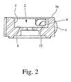
- im Schnitt den unteren Teil des Gehäuses gemäß
Fig. 1 , - Fig. 3
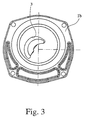
- in einer Ansicht von der Seite des Pumpraums her den oberen Teil des Gehäuses (Deckel),
- Fig. 4
- in einer Stirnansicht einen Rotor einer erfindungsgemäßen Hybrid- pumpe,
- Fig. 5
- den Rotor aus
Fig. 4 in einer perspektivischen Ansicht, bewegliche Rotorflügel demontiert, und - Fig. 6
- den Rotor aus
Fig. 4 in einer Stirnansicht von der Rückseite aus ge- sehen. - Das dargestellte Ausführungsbeispiel zeigt eine Hybridpumpe zum Fördern eines flüssiges Pumpmediums, also eine Pumpe, die aufgrund der Konstruktion des Rotors sowohl als Verdrängermaschine (Flügelzellenpumpe) als auch als Strömungsmaschine (Kreiselpumpe) arbeiten kann.
- Die Hybridpumpe hat ein Gehäuse 1, von dem man in
Fig. 1 und2 das Unterteil 1a sieht währendFig. 3 das Oberteil 1b, also praktisch den Deckel für das Unterteil 1a zeigt. Das Gehäuse 1 weist einen Pumpraum 2 auf. In den Pumpraum 2 mündet ein Einlaß 3, zu erkennen inFig. 3 im Oberteil 1b des Gehäuses 1. Hier haben wir es also mit einem axialen Einlaß 3 zu tun, dessen Kontur auf die Gestaltung des weiter unten zu erläuternden Rotors abgestimmt ist. - Der Pumpraum 2 weist ferner einen aus dem Pumpraum 2 herausführenden Auslaß 4 auf, der in
Fig. 2 zu erkennen ist. Der Auslaß 4 könnte, wie im Stand der Technik, ebenfalls axial angeordnet sein. Das dargestellte und bevorzugte Ausführungsbeispiel zeigt jedoch den Auslaß 4 tangential vom Pumpraum 2 abgehend. Die damit verbundenen Vorteile werden weiter unten noch erläutert. - In dem Pumpraum 2 ist ein um eine Rotorachse 5 drehbarer Rotor 6 angeordnet. Dieser besteht im dargestellten und bevorzugten Ausführungsbeispiel aus im wesentlichen nicht elastischem Kunststoff. Insbesondere kommt PEEK (Polyetheretherketon) in Frage. Insbesondere sollte es sich um einen chemisch beständigen Kunststoff handeln, damit die anmeldungsgemäße Hybridpumpe im Bereich chemischer Anwendungen problemlos eingesetzt werden kann.
- Für die beabsichtigte Funktionsweise ist es zweckmäßig, daß der Pumpraum 2 eine im Querschnitt im wesentlichen kreisrunde oder eine stetig verlaufende, zwar etwas von der Kreisform abweichende, aber immer noch zu einer Rotationsbewegung des Rotors 6 passende Lauffläche 7 aufweist. An den beiden Seiten des Rotors 6, also nicht an dessen Umfang, hat der Pumpraum 2 jeweils eine Seitenfläche 8; 8'.
- Um die Funktion als Verdrängermaschine ausüben zu können, ist der Rotor 6 bezogen auf die Lauffläche 7 exzentrisch im Pumpraum 2 angeordnet. Dabei weist der Rotor 6 einen der unteren Seitenfläche 8 des Pumpraums 2, die in
Fig. 1 und2 angedeutet ist, zugeordnete Grundplatte 9 auf. Der Rotor 6 ist in denFig. 4 bis 6 im einzelnen dargestellt. Die Grundplatte 9 ist insbesondere inFig. 5 und6 bezeichnet. - Der Rotor 6 weist ferner mehrere, in Umfangsrichtung im wesentlichen gleichmäßig beabstandet angeordnete, sich bei eingebautem Rotor 6 zur gegenüberliegenden Seitenfläche 8' des Pumpraums 2, angedeutet in
Fig. 3 , erstreckende Rotorteile 10 auf, die mit der Grundplatte 9 fest verbunden sind. Die Einheit aus Grundplatte 9 und Rotorteilen 10 stellt also gewissermaßen den Grundkörper des Rotors 6 dar. Dieser Grundkörper ist inFig. 5 in perspektivischer Ansicht dargestellt. - Am äußeren Ende jedes Rotorteils 10 ist ein vorzugsweise gebogener Rotorflügel 11 schwenkbar angelenkt. Man sieht die Schwenkgelenke 12 für die Rotorflügel 11 in
Fig. 4 , entsprechende Teile der Schwenkgelenke 12 auch inFig. 5 . InFig. 1 und6 sind diese ebenfalls zu erkennen, aber nicht mit Bezugszeichen identifiziert. - Man erkennt in
Fig. 1 die unterschiedliche, durch die Rotation des Rotors 6 im Pumpraum 2 erzeugte Lage der Rotorflügel 11, die zu der gewünschten Pumpwirkung führt. - Zwischen benachbarten Rotorteilen 10 und Rotorflügeln 11 sind die Pumpkammern 13 des Rotors 6 ausgebildet. Diese sind zur oberen Seitenfläche 8' des Pumpraums 2 hin offen und deren Böden 13' werden durch die Grundplatte 9 des Rotors 6 gebildet.
-
Fig. 5 läßt besonders gut erkennen, daß die Böden 13' der Pumpkammern 13 vom äußeren Rand der Grundplatte 9 ausgehend nach innen zur Rotorachse 5 hin konkav-bogenförmig ansteigend verlaufen. Man erkennt dabei ferner die Besonderheit, daß die Böden 13' der Pumpkammern 13 zur Rotorachse 5 hin einen überlagerten spiralförmigen Verlauf aufweisen, also in gewisser Weise im Raum zur Rotorachse 5 hin tordiert sind. - Die dargestellte Form der Böden 13' der Pumpkammern 13 führt dazu, daß die Pumpkammern 13 vollständig gefüllt werden und das Pumpmedium auch in den der Rotorachse 5 zugewandten Teilen der Pumpkammern 13 vollständig ausgetauscht wird. Toträume entfallen. Die Strömung des Pumpmediums in den Pumpkammern 13 ist so gleichmäßig wie möglich.
- Bereits zuvor ist darauf hingewiesen worden, daß die Rotorflügel 11 vorzugsweise gebogen ausgeführt sind. Eine bogenförmige Ausführung der Rotorflügel 11 entspricht der drehrichtungsbezogenen Ausgestaltung des Rotors 6 insgesamt. Man erkennt die Vorteile gebogener Rotorflügel 11 in
Fig. 1 ganz besonders deutlich. Insbesondere ist dabei vorgesehen, daß auch bereits die feststehenden Rotorteile 10 in Umfangsrichtung des Rotors 6 gebogen verlaufen. Dadurch ergibt sich der insgesamt bogenförmige Verlauf der Pumpkammern 13. In Draufsicht auf den Rotor 6 gesehen verlaufen die Böden 13' der Pumpkammern 13 jeweils bogenförmig dem Verlauf des benachbarten feststehenden Rotorteils 10 folgend. - Durch die drehrichtungsbezogene Asymmetrie des Rotors 6 ergibt sich, daß im dargestellten und bevorzugten Ausführungsbeispiel die Grundplatte 9 am Außenumfang nicht etwa kreisringförmig verläuft, sondern einen stufenförmigen Verlauf aufweist. Man erkennt dies besonders gut in
Fig. 6 , die die Rückseite der Grundplatte 9 zeigt. - Aus
Fig. 5 undFig. 6 im Zusammenhang läßt sich entnehmen, daß im dargestellten und bevorzugten Ausführungsbeispiel die beweglichen Rotorflügel 11 sich bis in die Ebene der Grundplatte 9 erstrecken, und zwar vorzugsweise genau bis zu deren Unterseite. Der bogenförmige Verlauf der Innenseite der Rotorflügel 11 ist an den bogenförmigen Verlauf des Außenrandes der Böden 13' angepaßt, so daß die Rotorflügel 11 an den Außenrändern 14 der Böden 13' gut zur Anlage kommen. Das sieht man besonders gut inFig. 4 undFig. 6 . Diese Konstruktion schafft bei anliegenden Rotorflügeln 11 praktisch nach unten geschlossene Pumpkammern 13. -
Fig. 1 und2 lassen im Zusammenhang erkennen, daß im dargestellten und bevorzugten Ausführungsbeispiel, wie bereits einleitend erwähnt, der Auslaß 4 aus dem Pumpraum 2 in der Lauffläche 7 des Pumpraums 2 angeordnet ist. Die Rotorflügel 11 überstreichen also beim Rotieren des Rotors 6 mit hoher Drehzahl, beispielsweise 8000 U/min, dauernd den Auslaß 4. Auch wenn das Material des Rotors 6 und seiner Rotorflügel 11 aus Kunststoff weitgehend unelastisch und verwindungssteif ist, so ergibt sich doch ein beachtlicher Verschleiß der radial außen liegenden Enden der Rotorflügel 11 beim beständigen Aufschlagen auf die Ränder des Auslasses 4. - Erfindungsgemäß ist hier nun vorgesehen, daß mindestens eine den Auslaß 4 schienenartig überbrückende Führungsleiste 15 für mindestens einen Außenrand der Rotorflügel 11 vorgesehen ist. In
Fig. 2 ist das die Führungsleiste 15 unten zur unteren Seitenfläche 8 hin. Vorzugsweise positioniert man je eine Führungsleiste oberhalb und unterhalb des Auslasses, so daß die äußeren Enden der Rotorflügel 11 ganz gleichmäßig schienenartig über den Auslaß 4 hinweggeführt werden.
Claims (6)
- Hybridpumpe zum Fördern eines flüssigen Pumpmediums
mit einem Gehäuse (1), das einen Pumpraum (2) sowie einen in den Pumpraum (2) mündenden Einlaß (3) und einen aus dem Pumpraum (2) führenden Auslaß (4) aufweist, und
mit einem in dem Pumpraum (2) angeordneten, um eine Rotorachse (5) drehbaren Rotor (6), aus im wesentlichen nicht elastischem, vorzugsweise chemisch beständigem Kunststoff, insbesondere PEEK,
wobei der Pumpraum (2) eine im Querschnitt im wesentlichen kreisrunde oder rundliche Lauffläche (7) und seitlich an beiden Seiten des Rotors (6) jeweils eine Seitenfläche (8; 8') aufweist,
wobei der Rotor (6) bezogen auf die Lauffläche (7) exzentrisch im Pumpraum (2) angeordnet ist,
wobei der Rotor (6) eine der unteren Seitenfläche (8) des Pumpraums (2) zugeordnete Grundplatte (9) und mehrere, in Umfangsrichtung im wesentlichen gleichmäßig beabstandet angeordnete, sich zur gegenüberliegenden Seitenfläche (8') des Pumpraums (2) erstreckende, mit der Grundplatte (9), fest verbundenen Rotorteile (10) aufweist,
wobei am äußeren Ende jedes Rotorteils (10) ein vorzugsweise gebogener Rotorflügel (11) schwenkbar angelenkt ist und
wobei zwischen benachbarten Rotorteilen (10) und Rotorflügeln (11) Pumpkammern (13) des Rotors (6) ausgebildet sind, die zur oberen Seitenfläche (8') des Pumpraums (2) hin offen sind und deren Böden (13') durch die Grundplatte (9) des Rotors (6) gebildet werden,
dadurch gekennzeichnet,
daß die Böden (13') der Pumpkammern (13) vom äußeren Rand der Grundplatte (9) ausgehend nach innen zur Rotorachse (5) hin konkav-bogenförmig ansteigend verlaufen. - Hybridpumpe nach Anspruch 1, dadurch gekennzeichnet,
daß die Böden (13') der Pumpkammern (13) zur Rotorachse (5) hin einen überlagerten spiralförmigen Verlauf aufweisen. - Hybridpumpe nach Anspruch 1 oder 2, dadurch gekennzeichnet,
daß die feststehenden Rotorteile (10) in Umfangsrichtung des Rotors (6) gebogen verlaufen und
daß in Draufsicht auf den Rotor (6) gesehen die Böden (13') der Pumpkammern (13) jeweils bogenförmig dem Verlauf des benachbarten feststehenden Rotorteils (10) folgend radial nach außen verlaufen. - Hybridpumpe nach Anspruch 3, dadurch gekennzeichnet,
daß die Grundplatte (9) am Außenumfang einen stufenförmigen Verlauf aufweist. - Hybridpumpe nach einem der Ansprüche 1 bis 4, dadurch gekennzeichnet,
daß die beweglichen Rotorflügel (11) sich bis in die Ebene der Grundplatte (9), vorzugsweise genau bis zu deren Unterseite, erstrecken und
daß der bogenförmige Verlauf der Innenseite der Rotorflügel (11) dem bogenförmigen Verlauf des Außenrandes der Böden (13') entspricht, so daß die Rotorflügel (11) an den Außenrändern (14) der Böden (13') gut zur Anlage kommen. - Hybridpumpe nach einem der Ansprüche 1 bis 5, dadurch gekennzeichnet,
daß der Auslaß (4) in der Lauffläche (7) des Pumpraums (2) angeordnet ist und
daß mindestens eine den Auslaß (4) schienenartig überbrückende Führungsleiste (15) für mindestens einen Außenrand der Rotorflügel (11) vorgesehen ist, wobei vorzugsweise oberhalb und unterhalb des Auslasses (4) je eine Führungsleiste vorgesehen ist.
Applications Claiming Priority (2)
| Application Number | Priority Date | Filing Date | Title |
|---|---|---|---|
| DE202007012565U DE202007012565U1 (de) | 2007-09-07 | 2007-09-07 | Hybridpumpe zum Fördern eines flüssigen Pumpmediums |
| PCT/EP2008/006186 WO2009033526A1 (de) | 2007-09-07 | 2008-07-28 | Hybridpumpe zum fördern eines flüssigen pumpmediums |
Publications (2)
| Publication Number | Publication Date |
|---|---|
| EP2160513A1 EP2160513A1 (de) | 2010-03-10 |
| EP2160513B1 true EP2160513B1 (de) | 2010-10-20 |
Family
ID=39895399
Family Applications (1)
| Application Number | Title | Priority Date | Filing Date |
|---|---|---|---|
| EP08785137A Not-in-force EP2160513B1 (de) | 2007-09-07 | 2008-07-28 | Hybridpumpe zum fördern eines flüssigen pumpmediums |
Country Status (7)
| Country | Link |
|---|---|
| US (1) | US8651844B2 (de) |
| EP (1) | EP2160513B1 (de) |
| AT (1) | ATE485449T1 (de) |
| AU (1) | AU2008298079A1 (de) |
| DE (2) | DE202007012565U1 (de) |
| ES (1) | ES2352311T3 (de) |
| WO (1) | WO2009033526A1 (de) |
Families Citing this family (2)
| Publication number | Priority date | Publication date | Assignee | Title |
|---|---|---|---|---|
| DE102017107643A1 (de) * | 2017-04-10 | 2018-10-11 | Biotrans Ag | Impellerpumpe |
| CN117329127B (zh) * | 2023-12-01 | 2024-02-02 | 成都理工大学 | 一种滑片式与离心式复合的压缩机械 |
Family Cites Families (8)
| Publication number | Priority date | Publication date | Assignee | Title |
|---|---|---|---|---|
| US3953146A (en) * | 1974-08-15 | 1976-04-27 | Whirlpool Corporation | Apparatus for treating lint in an automatic washer |
| DE2916858A1 (de) * | 1979-04-26 | 1980-11-06 | Dieter Brox | Universelle hochdruck innenzahnradpumpe |
| US6659744B1 (en) * | 2001-04-17 | 2003-12-09 | Charles Dow Raymond, Jr. | Rotary two axis expansible chamber pump with pivotal link |
| DE10158146A1 (de) | 2001-11-28 | 2003-06-18 | Horn Gmbh & Co Kg | Selbstansaugende Hybridpumpe |
| KR101172370B1 (ko) * | 2003-09-04 | 2012-08-08 | 파워 소스 테크놀로지스 인코퍼레이티드 | 유성 로터리 내연 엔진 |
| KR100590504B1 (ko) * | 2005-03-04 | 2006-06-19 | 엘지전자 주식회사 | 선회베인 압축기의 용량가변장치 |
| KR20080025366A (ko) * | 2005-04-29 | 2008-03-20 | 텐딕스 디벨롭먼트, 엘엘씨 | 래디얼 임펄스 엔진, 펌프 및 압축기 시스템과 관련 동작방법 |
| DE202005007789U1 (de) | 2005-05-12 | 2006-09-21 | Horn Gmbh & Co. Kg | Pumpe, insbesondere Hybridpumpe |
-
2007
- 2007-09-07 DE DE202007012565U patent/DE202007012565U1/de not_active Expired - Lifetime
-
2008
- 2008-07-28 ES ES08785137T patent/ES2352311T3/es active Active
- 2008-07-28 US US12/673,282 patent/US8651844B2/en not_active Expired - Fee Related
- 2008-07-28 AT AT08785137T patent/ATE485449T1/de active
- 2008-07-28 WO PCT/EP2008/006186 patent/WO2009033526A1/de not_active Ceased
- 2008-07-28 DE DE502008001606T patent/DE502008001606D1/de active Active
- 2008-07-28 EP EP08785137A patent/EP2160513B1/de not_active Not-in-force
- 2008-07-28 AU AU2008298079A patent/AU2008298079A1/en not_active Abandoned
Also Published As
| Publication number | Publication date |
|---|---|
| AU2008298079A1 (en) | 2009-03-19 |
| WO2009033526A1 (de) | 2009-03-19 |
| DE202007012565U1 (de) | 2009-01-22 |
| EP2160513A1 (de) | 2010-03-10 |
| ES2352311T3 (es) | 2011-02-17 |
| DE502008001606D1 (de) | 2010-12-02 |
| US20110236241A1 (en) | 2011-09-29 |
| US8651844B2 (en) | 2014-02-18 |
| ATE485449T1 (de) | 2010-11-15 |
Similar Documents
| Publication | Publication Date | Title |
|---|---|---|
| EP1134417A2 (de) | Verdrängerpumpe | |
| WO2015169496A1 (de) | Laufrad, insbesondere für eine seitenkanalmaschine | |
| WO2011029847A2 (de) | Drehkolbenpumpe | |
| DE2838607C2 (de) | Parallel- und innenachsige Umlaufkolbenmaschine | |
| EP1797327B1 (de) | Drehkolbenpumpe mit einem pumpengehäuse und zwei zweiflügeligen drehkolben | |
| DE102009055945B4 (de) | Flügelzellenpumpe | |
| DE2602543A1 (de) | Drehschieberpumpe | |
| EP1766237B1 (de) | Einflügelvakuumpumpe | |
| WO2009033526A1 (de) | Hybridpumpe zum fördern eines flüssigen pumpmediums | |
| DE102014212920A1 (de) | Schaufelpumpe | |
| WO2004076788A1 (de) | Getriebe, insbesondere schlagleistengetriebe für ein fenster oder dergleichen | |
| DE102012210257A1 (de) | Pumpe | |
| EP2606235B1 (de) | Flügelzellenpumpe | |
| DE102019127389A1 (de) | Flügelzellenpumpe | |
| DE102007039157B4 (de) | Flügelzellenpumpe | |
| WO2006120006A1 (de) | Pumpe, insbesondere hybridpumpe | |
| DE7630369U1 (de) | Hydraulische maschine mit axial angeordneten kolben | |
| DE10022097C1 (de) | Kreiskolbenpumpe | |
| DE4236564A1 (en) | Rotary pump with vanes in pairs - has outer contact edge on each vane in plane of surface towards compartment and has passage formed by grooves in faces of vanes | |
| DE6921357U (de) | Abwasserpumpe | |
| DE1503333C3 (de) | Rotationskolbenmaschine | |
| DE10227234A1 (de) | Fördereinrichtung zum Fördern insbesondere von gasförmigen oder flüssigen Medien | |
| DE102004037561A1 (de) | Drehkolbenpumpe | |
| DE202013006419U1 (de) | Messer | |
| DE4236721A1 (en) | Rotary vane pump for fluid - has compartments connected during compression to underside of next vanes via non-return valves |
Legal Events
| Date | Code | Title | Description |
|---|---|---|---|
| PUAI | Public reference made under article 153(3) epc to a published international application that has entered the european phase |
Free format text: ORIGINAL CODE: 0009012 |
|
| 17P | Request for examination filed |
Effective date: 20100107 |
|
| AK | Designated contracting states |
Kind code of ref document: A1 Designated state(s): AT BE BG CH CY CZ DE DK EE ES FI FR GB GR HR HU IE IS IT LI LT LU LV MC MT NL NO PL PT RO SE SI SK TR |
|
| AX | Request for extension of the european patent |
Extension state: AL BA MK RS |
|
| GRAP | Despatch of communication of intention to grant a patent |
Free format text: ORIGINAL CODE: EPIDOSNIGR1 |
|
| RBV | Designated contracting states (corrected) |
Designated state(s): AT BE BG CH CY CZ DE DK EE ES FI FR GB GR HR HU IE IS IT LI LT LU LV MC MT NL NO PL PT RO SE SI SK TR |
|
| RIN1 | Information on inventor provided before grant (corrected) |
Inventor name: DIEKMANN, RALF |
|
| GRAS | Grant fee paid |
Free format text: ORIGINAL CODE: EPIDOSNIGR3 |
|
| GRAA | (expected) grant |
Free format text: ORIGINAL CODE: 0009210 |
|
| AK | Designated contracting states |
Kind code of ref document: B1 Designated state(s): AT BE BG CH CY CZ DE DK EE ES FI FR GB GR HR HU IE IS IT LI LT LU LV MC MT NL NO PL PT RO SE SI SK TR |
|
| REG | Reference to a national code |
Ref country code: GB Ref legal event code: FG4D Free format text: NOT ENGLISH |
|
| REG | Reference to a national code |
Ref country code: CH Ref legal event code: EP |
|
| REG | Reference to a national code |
Ref country code: IE Ref legal event code: FG4D Free format text: LANGUAGE OF EP DOCUMENT: GERMAN |
|
| REF | Corresponds to: |
Ref document number: 502008001606 Country of ref document: DE Date of ref document: 20101202 Kind code of ref document: P |
|
| REG | Reference to a national code |
Ref country code: NL Ref legal event code: T3 |
|
| REG | Reference to a national code |
Ref country code: ES Ref legal event code: FG2A Effective date: 20110207 |
|
| LTIE | Lt: invalidation of european patent or patent extension |
Effective date: 20101020 |
|
| PG25 | Lapsed in a contracting state [announced via postgrant information from national office to epo] |
Ref country code: LT Free format text: LAPSE BECAUSE OF FAILURE TO SUBMIT A TRANSLATION OF THE DESCRIPTION OR TO PAY THE FEE WITHIN THE PRESCRIBED TIME-LIMIT Effective date: 20101020 Ref country code: NO Free format text: LAPSE BECAUSE OF FAILURE TO SUBMIT A TRANSLATION OF THE DESCRIPTION OR TO PAY THE FEE WITHIN THE PRESCRIBED TIME-LIMIT Effective date: 20110120 |
|
| REG | Reference to a national code |
Ref country code: IE Ref legal event code: FD4D |
|
| PG25 | Lapsed in a contracting state [announced via postgrant information from national office to epo] |
Ref country code: IS Free format text: LAPSE BECAUSE OF FAILURE TO SUBMIT A TRANSLATION OF THE DESCRIPTION OR TO PAY THE FEE WITHIN THE PRESCRIBED TIME-LIMIT Effective date: 20110220 Ref country code: PT Free format text: LAPSE BECAUSE OF FAILURE TO SUBMIT A TRANSLATION OF THE DESCRIPTION OR TO PAY THE FEE WITHIN THE PRESCRIBED TIME-LIMIT Effective date: 20110221 Ref country code: HR Free format text: LAPSE BECAUSE OF FAILURE TO SUBMIT A TRANSLATION OF THE DESCRIPTION OR TO PAY THE FEE WITHIN THE PRESCRIBED TIME-LIMIT Effective date: 20101020 Ref country code: LV Free format text: LAPSE BECAUSE OF FAILURE TO SUBMIT A TRANSLATION OF THE DESCRIPTION OR TO PAY THE FEE WITHIN THE PRESCRIBED TIME-LIMIT Effective date: 20101020 Ref country code: FI Free format text: LAPSE BECAUSE OF FAILURE TO SUBMIT A TRANSLATION OF THE DESCRIPTION OR TO PAY THE FEE WITHIN THE PRESCRIBED TIME-LIMIT Effective date: 20101020 Ref country code: SE Free format text: LAPSE BECAUSE OF FAILURE TO SUBMIT A TRANSLATION OF THE DESCRIPTION OR TO PAY THE FEE WITHIN THE PRESCRIBED TIME-LIMIT Effective date: 20101020 Ref country code: SI Free format text: LAPSE BECAUSE OF FAILURE TO SUBMIT A TRANSLATION OF THE DESCRIPTION OR TO PAY THE FEE WITHIN THE PRESCRIBED TIME-LIMIT Effective date: 20101020 Ref country code: BG Free format text: LAPSE BECAUSE OF FAILURE TO SUBMIT A TRANSLATION OF THE DESCRIPTION OR TO PAY THE FEE WITHIN THE PRESCRIBED TIME-LIMIT Effective date: 20110120 |
|
| PG25 | Lapsed in a contracting state [announced via postgrant information from national office to epo] |
Ref country code: GR Free format text: LAPSE BECAUSE OF FAILURE TO SUBMIT A TRANSLATION OF THE DESCRIPTION OR TO PAY THE FEE WITHIN THE PRESCRIBED TIME-LIMIT Effective date: 20110121 |
|
| PG25 | Lapsed in a contracting state [announced via postgrant information from national office to epo] |
Ref country code: CZ Free format text: LAPSE BECAUSE OF FAILURE TO SUBMIT A TRANSLATION OF THE DESCRIPTION OR TO PAY THE FEE WITHIN THE PRESCRIBED TIME-LIMIT Effective date: 20101020 Ref country code: EE Free format text: LAPSE BECAUSE OF FAILURE TO SUBMIT A TRANSLATION OF THE DESCRIPTION OR TO PAY THE FEE WITHIN THE PRESCRIBED TIME-LIMIT Effective date: 20101020 Ref country code: IE Free format text: LAPSE BECAUSE OF FAILURE TO SUBMIT A TRANSLATION OF THE DESCRIPTION OR TO PAY THE FEE WITHIN THE PRESCRIBED TIME-LIMIT Effective date: 20101020 |
|
| PLBE | No opposition filed within time limit |
Free format text: ORIGINAL CODE: 0009261 |
|
| STAA | Information on the status of an ep patent application or granted ep patent |
Free format text: STATUS: NO OPPOSITION FILED WITHIN TIME LIMIT |
|
| PG25 | Lapsed in a contracting state [announced via postgrant information from national office to epo] |
Ref country code: SK Free format text: LAPSE BECAUSE OF FAILURE TO SUBMIT A TRANSLATION OF THE DESCRIPTION OR TO PAY THE FEE WITHIN THE PRESCRIBED TIME-LIMIT Effective date: 20101020 Ref country code: DK Free format text: LAPSE BECAUSE OF FAILURE TO SUBMIT A TRANSLATION OF THE DESCRIPTION OR TO PAY THE FEE WITHIN THE PRESCRIBED TIME-LIMIT Effective date: 20101020 Ref country code: RO Free format text: LAPSE BECAUSE OF FAILURE TO SUBMIT A TRANSLATION OF THE DESCRIPTION OR TO PAY THE FEE WITHIN THE PRESCRIBED TIME-LIMIT Effective date: 20101020 Ref country code: PL Free format text: LAPSE BECAUSE OF FAILURE TO SUBMIT A TRANSLATION OF THE DESCRIPTION OR TO PAY THE FEE WITHIN THE PRESCRIBED TIME-LIMIT Effective date: 20101020 |
|
| 26N | No opposition filed |
Effective date: 20110721 |
|
| REG | Reference to a national code |
Ref country code: DE Ref legal event code: R097 Ref document number: 502008001606 Country of ref document: DE Effective date: 20110721 |
|
| PG25 | Lapsed in a contracting state [announced via postgrant information from national office to epo] |
Ref country code: MT Free format text: LAPSE BECAUSE OF FAILURE TO SUBMIT A TRANSLATION OF THE DESCRIPTION OR TO PAY THE FEE WITHIN THE PRESCRIBED TIME-LIMIT Effective date: 20101020 |
|
| BERE | Be: lapsed |
Owner name: HORN G.M.B.H. & CO. KG Effective date: 20110731 |
|
| PG25 | Lapsed in a contracting state [announced via postgrant information from national office to epo] |
Ref country code: MC Free format text: LAPSE BECAUSE OF NON-PAYMENT OF DUE FEES Effective date: 20110731 |
|
| REG | Reference to a national code |
Ref country code: DE Ref legal event code: R082 Ref document number: 502008001606 Country of ref document: DE Representative=s name: HANS-HERBERT STOFFREGEN, DE Ref country code: DE Ref legal event code: R082 Ref document number: 502008001606 Country of ref document: DE Representative=s name: STOFFREGEN, HANS-HERBERT, DIPL.-PHYS. DR.RER.N, DE |
|
| PG25 | Lapsed in a contracting state [announced via postgrant information from national office to epo] |
Ref country code: BE Free format text: LAPSE BECAUSE OF NON-PAYMENT OF DUE FEES Effective date: 20110731 |
|
| PGFP | Annual fee paid to national office [announced via postgrant information from national office to epo] |
Ref country code: IT Payment date: 20120727 Year of fee payment: 5 Ref country code: ES Payment date: 20120724 Year of fee payment: 5 Ref country code: FR Payment date: 20120808 Year of fee payment: 5 Ref country code: DE Payment date: 20120721 Year of fee payment: 5 |
|
| PGFP | Annual fee paid to national office [announced via postgrant information from national office to epo] |
Ref country code: NL Payment date: 20120828 Year of fee payment: 5 |
|
| PG25 | Lapsed in a contracting state [announced via postgrant information from national office to epo] |
Ref country code: CY Free format text: LAPSE BECAUSE OF EXPIRATION OF PROTECTION Effective date: 20101020 Ref country code: LU Free format text: LAPSE BECAUSE OF NON-PAYMENT OF DUE FEES Effective date: 20110728 |
|
| PG25 | Lapsed in a contracting state [announced via postgrant information from national office to epo] |
Ref country code: TR Free format text: LAPSE BECAUSE OF FAILURE TO SUBMIT A TRANSLATION OF THE DESCRIPTION OR TO PAY THE FEE WITHIN THE PRESCRIBED TIME-LIMIT Effective date: 20101020 |
|
| PG25 | Lapsed in a contracting state [announced via postgrant information from national office to epo] |
Ref country code: HU Free format text: LAPSE BECAUSE OF FAILURE TO SUBMIT A TRANSLATION OF THE DESCRIPTION OR TO PAY THE FEE WITHIN THE PRESCRIBED TIME-LIMIT Effective date: 20101020 |
|
| PGFP | Annual fee paid to national office [announced via postgrant information from national office to epo] |
Ref country code: GB Payment date: 20130719 Year of fee payment: 6 |
|
| REG | Reference to a national code |
Ref country code: NL Ref legal event code: V1 Effective date: 20140201 |
|
| REG | Reference to a national code |
Ref country code: CH Ref legal event code: PL |
|
| REG | Reference to a national code |
Ref country code: FR Ref legal event code: ST Effective date: 20140331 |
|
| PG25 | Lapsed in a contracting state [announced via postgrant information from national office to epo] |
Ref country code: LI Free format text: LAPSE BECAUSE OF NON-PAYMENT OF DUE FEES Effective date: 20130731 Ref country code: CH Free format text: LAPSE BECAUSE OF NON-PAYMENT OF DUE FEES Effective date: 20130731 Ref country code: NL Free format text: LAPSE BECAUSE OF NON-PAYMENT OF DUE FEES Effective date: 20140201 Ref country code: DE Free format text: LAPSE BECAUSE OF NON-PAYMENT OF DUE FEES Effective date: 20140201 |
|
| REG | Reference to a national code |
Ref country code: DE Ref legal event code: R119 Ref document number: 502008001606 Country of ref document: DE Effective date: 20140201 |
|
| PG25 | Lapsed in a contracting state [announced via postgrant information from national office to epo] |
Ref country code: IT Free format text: LAPSE BECAUSE OF NON-PAYMENT OF DUE FEES Effective date: 20130728 Ref country code: FR Free format text: LAPSE BECAUSE OF NON-PAYMENT OF DUE FEES Effective date: 20130731 |
|
| REG | Reference to a national code |
Ref country code: AT Ref legal event code: MM01 Ref document number: 485449 Country of ref document: AT Kind code of ref document: T Effective date: 20130728 |
|
| REG | Reference to a national code |
Ref country code: ES Ref legal event code: FD2A Effective date: 20141009 |
|
| PG25 | Lapsed in a contracting state [announced via postgrant information from national office to epo] |
Ref country code: AT Free format text: LAPSE BECAUSE OF NON-PAYMENT OF DUE FEES Effective date: 20130728 |
|
| PG25 | Lapsed in a contracting state [announced via postgrant information from national office to epo] |
Ref country code: ES Free format text: LAPSE BECAUSE OF NON-PAYMENT OF DUE FEES Effective date: 20130729 |
|
| GBPC | Gb: european patent ceased through non-payment of renewal fee |
Effective date: 20140728 |
|
| PG25 | Lapsed in a contracting state [announced via postgrant information from national office to epo] |
Ref country code: GB Free format text: LAPSE BECAUSE OF NON-PAYMENT OF DUE FEES Effective date: 20140728 |