EP2159440B1 - Dispositif de commande d'embrayage et procédé de calcul de la quantité de correction de commande d'embrayage - Google Patents
Dispositif de commande d'embrayage et procédé de calcul de la quantité de correction de commande d'embrayage Download PDFInfo
- Publication number
- EP2159440B1 EP2159440B1 EP09167315A EP09167315A EP2159440B1 EP 2159440 B1 EP2159440 B1 EP 2159440B1 EP 09167315 A EP09167315 A EP 09167315A EP 09167315 A EP09167315 A EP 09167315A EP 2159440 B1 EP2159440 B1 EP 2159440B1
- Authority
- EP
- European Patent Office
- Prior art keywords
- clutch
- correction amount
- oil pressure
- control correction
- stroke end
- Prior art date
- Legal status (The legal status is an assumption and is not a legal conclusion. Google has not performed a legal analysis and makes no representation as to the accuracy of the status listed.)
- Active
Links
- 238000012937 correction Methods 0.000 title claims description 71
- 238000000034 method Methods 0.000 title claims description 14
- 230000005540 biological transmission Effects 0.000 claims description 25
- 239000012530 fluid Substances 0.000 claims description 10
- 239000003921 oil Substances 0.000 description 88
- 238000012545 processing Methods 0.000 description 13
- 238000010586 diagram Methods 0.000 description 8
- 230000007935 neutral effect Effects 0.000 description 7
- 230000002093 peripheral effect Effects 0.000 description 4
- 230000006866 deterioration Effects 0.000 description 3
- 230000000694 effects Effects 0.000 description 2
- 238000007689 inspection Methods 0.000 description 2
- 230000002411 adverse Effects 0.000 description 1
- 238000013461 design Methods 0.000 description 1
- 238000006073 displacement reaction Methods 0.000 description 1
- 239000010687 lubricating oil Substances 0.000 description 1
- 238000012986 modification Methods 0.000 description 1
- 230000004048 modification Effects 0.000 description 1
- 230000002265 prevention Effects 0.000 description 1
Images


Classifications
-
- F—MECHANICAL ENGINEERING; LIGHTING; HEATING; WEAPONS; BLASTING
- F16—ENGINEERING ELEMENTS AND UNITS; GENERAL MEASURES FOR PRODUCING AND MAINTAINING EFFECTIVE FUNCTIONING OF MACHINES OR INSTALLATIONS; THERMAL INSULATION IN GENERAL
- F16D—COUPLINGS FOR TRANSMITTING ROTATION; CLUTCHES; BRAKES
- F16D48/00—External control of clutches
- F16D48/06—Control by electric or electronic means, e.g. of fluid pressure
- F16D48/066—Control of fluid pressure, e.g. using an accumulator
-
- F—MECHANICAL ENGINEERING; LIGHTING; HEATING; WEAPONS; BLASTING
- F16—ENGINEERING ELEMENTS AND UNITS; GENERAL MEASURES FOR PRODUCING AND MAINTAINING EFFECTIVE FUNCTIONING OF MACHINES OR INSTALLATIONS; THERMAL INSULATION IN GENERAL
- F16D—COUPLINGS FOR TRANSMITTING ROTATION; CLUTCHES; BRAKES
- F16D25/00—Fluid-actuated clutches
- F16D25/06—Fluid-actuated clutches in which the fluid actuates a piston incorporated in, i.e. rotating with the clutch
- F16D25/062—Fluid-actuated clutches in which the fluid actuates a piston incorporated in, i.e. rotating with the clutch the clutch having friction surfaces
- F16D25/063—Fluid-actuated clutches in which the fluid actuates a piston incorporated in, i.e. rotating with the clutch the clutch having friction surfaces with clutch members exclusively moving axially
- F16D25/0635—Fluid-actuated clutches in which the fluid actuates a piston incorporated in, i.e. rotating with the clutch the clutch having friction surfaces with clutch members exclusively moving axially with flat friction surfaces, e.g. discs
- F16D25/0638—Fluid-actuated clutches in which the fluid actuates a piston incorporated in, i.e. rotating with the clutch the clutch having friction surfaces with clutch members exclusively moving axially with flat friction surfaces, e.g. discs with more than two discs, e.g. multiple lamellae
-
- F—MECHANICAL ENGINEERING; LIGHTING; HEATING; WEAPONS; BLASTING
- F16—ENGINEERING ELEMENTS AND UNITS; GENERAL MEASURES FOR PRODUCING AND MAINTAINING EFFECTIVE FUNCTIONING OF MACHINES OR INSTALLATIONS; THERMAL INSULATION IN GENERAL
- F16D—COUPLINGS FOR TRANSMITTING ROTATION; CLUTCHES; BRAKES
- F16D25/00—Fluid-actuated clutches
- F16D25/10—Clutch systems with a plurality of fluid-actuated clutches
-
- F—MECHANICAL ENGINEERING; LIGHTING; HEATING; WEAPONS; BLASTING
- F16—ENGINEERING ELEMENTS AND UNITS; GENERAL MEASURES FOR PRODUCING AND MAINTAINING EFFECTIVE FUNCTIONING OF MACHINES OR INSTALLATIONS; THERMAL INSULATION IN GENERAL
- F16D—COUPLINGS FOR TRANSMITTING ROTATION; CLUTCHES; BRAKES
- F16D2500/00—External control of clutches by electric or electronic means
- F16D2500/10—System to be controlled
- F16D2500/104—Clutch
- F16D2500/10443—Clutch type
- F16D2500/1045—Friction clutch
-
- F—MECHANICAL ENGINEERING; LIGHTING; HEATING; WEAPONS; BLASTING
- F16—ENGINEERING ELEMENTS AND UNITS; GENERAL MEASURES FOR PRODUCING AND MAINTAINING EFFECTIVE FUNCTIONING OF MACHINES OR INSTALLATIONS; THERMAL INSULATION IN GENERAL
- F16D—COUPLINGS FOR TRANSMITTING ROTATION; CLUTCHES; BRAKES
- F16D2500/00—External control of clutches by electric or electronic means
- F16D2500/10—System to be controlled
- F16D2500/11—Application
- F16D2500/1107—Vehicles
- F16D2500/1117—Motorcycle
-
- F—MECHANICAL ENGINEERING; LIGHTING; HEATING; WEAPONS; BLASTING
- F16—ENGINEERING ELEMENTS AND UNITS; GENERAL MEASURES FOR PRODUCING AND MAINTAINING EFFECTIVE FUNCTIONING OF MACHINES OR INSTALLATIONS; THERMAL INSULATION IN GENERAL
- F16D—COUPLINGS FOR TRANSMITTING ROTATION; CLUTCHES; BRAKES
- F16D2500/00—External control of clutches by electric or electronic means
- F16D2500/30—Signal inputs
- F16D2500/302—Signal inputs from the actuator
- F16D2500/3024—Pressure
-
- F—MECHANICAL ENGINEERING; LIGHTING; HEATING; WEAPONS; BLASTING
- F16—ENGINEERING ELEMENTS AND UNITS; GENERAL MEASURES FOR PRODUCING AND MAINTAINING EFFECTIVE FUNCTIONING OF MACHINES OR INSTALLATIONS; THERMAL INSULATION IN GENERAL
- F16D—COUPLINGS FOR TRANSMITTING ROTATION; CLUTCHES; BRAKES
- F16D2500/00—External control of clutches by electric or electronic means
- F16D2500/30—Signal inputs
- F16D2500/302—Signal inputs from the actuator
- F16D2500/3026—Stroke
-
- F—MECHANICAL ENGINEERING; LIGHTING; HEATING; WEAPONS; BLASTING
- F16—ENGINEERING ELEMENTS AND UNITS; GENERAL MEASURES FOR PRODUCING AND MAINTAINING EFFECTIVE FUNCTIONING OF MACHINES OR INSTALLATIONS; THERMAL INSULATION IN GENERAL
- F16D—COUPLINGS FOR TRANSMITTING ROTATION; CLUTCHES; BRAKES
- F16D2500/00—External control of clutches by electric or electronic means
- F16D2500/30—Signal inputs
- F16D2500/304—Signal inputs from the clutch
- F16D2500/30404—Clutch temperature
-
- F—MECHANICAL ENGINEERING; LIGHTING; HEATING; WEAPONS; BLASTING
- F16—ENGINEERING ELEMENTS AND UNITS; GENERAL MEASURES FOR PRODUCING AND MAINTAINING EFFECTIVE FUNCTIONING OF MACHINES OR INSTALLATIONS; THERMAL INSULATION IN GENERAL
- F16D—COUPLINGS FOR TRANSMITTING ROTATION; CLUTCHES; BRAKES
- F16D2500/00—External control of clutches by electric or electronic means
- F16D2500/30—Signal inputs
- F16D2500/308—Signal inputs from the transmission
- F16D2500/30802—Transmission oil properties
- F16D2500/30803—Oil temperature
-
- F—MECHANICAL ENGINEERING; LIGHTING; HEATING; WEAPONS; BLASTING
- F16—ENGINEERING ELEMENTS AND UNITS; GENERAL MEASURES FOR PRODUCING AND MAINTAINING EFFECTIVE FUNCTIONING OF MACHINES OR INSTALLATIONS; THERMAL INSULATION IN GENERAL
- F16D—COUPLINGS FOR TRANSMITTING ROTATION; CLUTCHES; BRAKES
- F16D2500/00—External control of clutches by electric or electronic means
- F16D2500/50—Problem to be solved by the control system
- F16D2500/502—Relating the clutch
- F16D2500/50245—Calibration or recalibration of the clutch touch-point
- F16D2500/50251—During operation
-
- F—MECHANICAL ENGINEERING; LIGHTING; HEATING; WEAPONS; BLASTING
- F16—ENGINEERING ELEMENTS AND UNITS; GENERAL MEASURES FOR PRODUCING AND MAINTAINING EFFECTIVE FUNCTIONING OF MACHINES OR INSTALLATIONS; THERMAL INSULATION IN GENERAL
- F16D—COUPLINGS FOR TRANSMITTING ROTATION; CLUTCHES; BRAKES
- F16D2500/00—External control of clutches by electric or electronic means
- F16D2500/70—Details about the implementation of the control system
- F16D2500/704—Output parameters from the control unit; Target parameters to be controlled
- F16D2500/70402—Actuator parameters
- F16D2500/7041—Position
- F16D2500/70414—Quick displacement to clutch touch point
-
- F—MECHANICAL ENGINEERING; LIGHTING; HEATING; WEAPONS; BLASTING
- F16—ENGINEERING ELEMENTS AND UNITS; GENERAL MEASURES FOR PRODUCING AND MAINTAINING EFFECTIVE FUNCTIONING OF MACHINES OR INSTALLATIONS; THERMAL INSULATION IN GENERAL
- F16H—GEARING
- F16H2342/00—Calibrating
- F16H2342/04—Calibrating engagement of friction elements
- F16H2342/042—Point of engagement
-
- F—MECHANICAL ENGINEERING; LIGHTING; HEATING; WEAPONS; BLASTING
- F16—ENGINEERING ELEMENTS AND UNITS; GENERAL MEASURES FOR PRODUCING AND MAINTAINING EFFECTIVE FUNCTIONING OF MACHINES OR INSTALLATIONS; THERMAL INSULATION IN GENERAL
- F16H—GEARING
- F16H61/00—Control functions within control units of change-speed- or reversing-gearings for conveying rotary motion ; Control of exclusively fluid gearing, friction gearing, gearings with endless flexible members or other particular types of gearing
- F16H61/68—Control functions within control units of change-speed- or reversing-gearings for conveying rotary motion ; Control of exclusively fluid gearing, friction gearing, gearings with endless flexible members or other particular types of gearing specially adapted for stepped gearings
- F16H61/684—Control functions within control units of change-speed- or reversing-gearings for conveying rotary motion ; Control of exclusively fluid gearing, friction gearing, gearings with endless flexible members or other particular types of gearing specially adapted for stepped gearings without interruption of drive
- F16H61/688—Control functions within control units of change-speed- or reversing-gearings for conveying rotary motion ; Control of exclusively fluid gearing, friction gearing, gearings with endless flexible members or other particular types of gearing specially adapted for stepped gearings without interruption of drive with two inputs, e.g. selection of one of two torque-flow paths by clutches
Definitions
- the present invention relates to a clutch control device and a clutch control correction amount calculating method, and more particularly to a clutch control device and a clutch control correction amount calculating method which can calculate a control correction amount for a clutch by detecting a load required for engagement of the clutch.
- a clutch device for connecting and disconnecting a rotational drive force from a power source to a transmission, wherein the engagement/disengagement of the clutch is automatically controlled by an actuator according to a starting operation or a shift operation.
- the clutch disks in such a clutch device are worn to cause a change in clutch condition, there is a possibility that the torque capacity of the clutch may be deviated to cause a change in running feel at starting or shifting.
- Japanese Patent Laid-Open No. 2004-197842 discloses a clutch device having such a configuration that the amount of movement of a given member driven by an actuator is detected to thereby obtain the stroke of the clutch disks until they come into contact with each other and that the drive amount for the actuator is changed according to a change in this stroke.
- a clutch control device for a hydraulic clutch for connecting and disconnecting a rotational drive force from an engine to a transmission in a vehicle, wherein clutch disks are operated in their engaging direction against a biasing force of a return spring by driving an actuator
- the clutch control device including clutch control means for controlling the clutch; stroke end detecting means for detecting that the clutch has reached a stroke end position where the clutch disks are in contact with each other; oil pressure detecting means for detecting an oil pressure supplied to the clutch; and control correction amount calculating means for calculating a work load generated in the return spring according to the oil pressure detected at the time the clutch has reached the stroke end position, and calculating a control correction amount for the clutch according to the difference between the work load calculated above and a predetermined reference value.
- the stroke end detecting means determines that the clutch has reached the stroke end position.
- the clutch is of a twin clutch type composed of a first clutch and a second clutch provided on a main shaft, and the engaged conditions of the first and second clutches are alternately switched in every shift operation to thereby transmit the rotational drive force from the engine to the transmission.
- the calculation of the control correction amount by the control correction amount calculating means is performed after the temperature of a hydraulic fluid for driving the clutch becomes higher than a predetermined value.
- the calculation of the control correction amount by the control correction amount calculating means is performed at given intervals.
- a clutch control correction amount calculating method for a hydraulic clutch for connecting and disconnecting a rotational drive force from an engine to a transmission in a vehicle, wherein clutch disks are operated in their engaging direction against a biasing force of a return spring by driving an actuator
- the clutch control correction amount calculating method including the steps of detecting that the clutch has reached a stroke end position where the clutch disks are in contact with each other; calculating a work load generated in the return spring according to an oil pressure detected at the time the clutch has reached the stroke end position; and calculating a control correction amount for the clutch according to the difference between the work load generated above and a predetermined reference value.
- the clutch control device includes the clutch control means for controlling the clutch, the stroke end detecting means for detecting that the clutch has reached the stroke end position where the clutch disks are in contact with each other, the oil pressure detecting means for detecting the oil pressure supplied to the clutch, and the control correction amount calculating means for calculating the work load generated in the return spring according to the oil pressure detected at the time the clutch has reached the stroke end position and calculating the control correction amount for the clutch according to the difference between the work load calculated above and the predetermined reference value.
- the stroke end detecting means determines that the clutch has reached the stroke end position when the rate of change in the oil pressure becomes larger than the predetermined value. Accordingly, the stroke end position of the clutch can be easily detected by using the characteristics that when the clutch disks come into contact with each other in driving the clutch in its engaging direction, the oil pressure is rapidly increased.
- the clutch is of a twin clutch type composed of the first clutch and the second clutch provided on the main shaft, and the engaged conditions of the first and second clutches are alternately switched in every shift operation to thereby transmit the rotational drive force from the engine to the transmission.
- the calculation of the control correction amount by the control correction amount calculating means is performed after the temperature of the hydraulic fluid for driving the clutch becomes higher than the predetermined value. Accordingly, the temperature condition in performing the calculation of the control correction amount can be set to thereby prevent an influence of a change in viscosity of the hydraulic fluid upon the result of calculation of the control correction amount.
- the calculation of the control correction amount by the control correction amount calculating means is performed at given intervals. Accordingly, the control correction amount for the clutch can be periodically updated, so that proper clutch control can be always performed.
- a warning is given by the warning means when the control correction amount for the clutch becomes larger than the predetermined value. Accordingly, it is possible to urge the operator to inspect or replace the clutch disks or the return spring.
- the clutch control correction amount calculating method includes the steps of detecting that the clutch has reached the stroke end position where the clutch disks are in contact with each other, calculating the work load generated in the return spring according to the oil pressure detected at the time the clutch has reached the stroke end position, and calculating the control correction amount for the clutch according to the difference between the work load generated above and the predetermined reference value. Accordingly, the work load on the return spring can be calculated according to the oil pressure supplied to the clutch without providing any special load sensor or the like, thereby obtaining the control correction amount for the clutch.
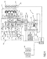
- Fig. 1 is a schematic diagram showing a system configuration of an automatic manual transmission (which will be hereinafter abbreviated to AMT) 16 as an automatic transmission and its peripheral devices applied to a motorcycle.
- AMT automatic manual transmission
- Fig. 2 is a layout diagram showing shafts and shift gear meshing in the AMT 16.
- the AMT 16 is a twin clutch type transmission having two clutches provided on a main shaft for connecting and disconnecting the transmission of a rotational drive force from an engine.
- the AMT 16 connected to an engine 11 is controlled in operation by a clutch hydraulic device 17 and an AMT control unit 18 as a shift control device.
- the engine 11 has a throttle-by-wire type throttle body 19, and this throttle body 19 is provided with a throttle opening/closing motor 20.
- the AMT 16 includes a forward six-speed transmission 21, first clutch CL1, second clutch CL2, shift drum 24, and shift control motor 25 for rotating the shift drum 24.
- Many gears constituting the transmission 21 are connected fixedly or loosely to a main shaft 26 and a counter shaft 27.
- the main shaft 26 is composed of an inner main shaft 26a and an outer main shaft 26b.
- the inner main shaft 26a is connected to the first clutch CL1, and the outer main shaft 26b is connected to the second clutch CL2.
- Shift gears are axially displaceably provided on the main shaft 26 and the counter shaft 27.
- Shift forks 23 are engaged at their opposite ends to these shift gears and guide grooves (not shown) formed on the shift drum 24.
- a primary drive gear 31 is connected to an output shaft of the engine 11, i.e., a crankshaft 30.
- the primary drive gear 31 is in mesh with a primary driven gear 32.
- the primary driven gear 32 is connected through the first clutch CL1 to the inner main shaft 26a and also connected through the second clutch CL2 to the outer main shaft 26b.
- the AMT 16 further includes an inner main shaft rotational speed sensor 73 and an outer main shaft rotational speed sensor 74 for respectively detecting the rotational speeds of the inner main shaft 26a and the outer main shaft 26b by measuring the rotational speeds of the predetermined shift gears on the counter shaft 27.
- a drive sprocket 35 is connected to the counter shaft 27, and a drive chain (not shown) is wrapped around the drive sprocket 35, so that a drive force is transmitted from the counter shaft 27 through the drive chain to a rear wheel as a drive wheel.
- the AMT 16 further includes an engine speed sensor 36 opposed to the outer circumference of the primary driven gear 32, a gear position sensor 38 for detecting the present gear position according to the rotational position of the shift drum 24, a shift sensor 64 for detecting the rotational position of a shifter driven by the shift control motor 25, and a neutral switch 63 for detecting the neutral position of the shift drum 24.
- the throttle body 19 is provided with a throttle angle sensor 47 for detecting a throttle angle.
- the clutch hydraulic device 17 uses a lubricating oil for the engine 11 as a hydraulic fluid for driving the clutch CL.
- the clutch hydraulic device 17 includes an oil tank 39 and an oil supply passage 40 for supplying oil (hydraulic fluid) from the oil tank 39 to the first clutch CL1 and the second clutch CL2.
- the oil supply passage 40 is provided with a hydraulic pump 41 as an oil pressure source and a valve (electronically controlled valve) 42 as an actuator.
- a return passage 43 is connected to the oil supply passage 40, and the return passage 43 is provided with a regulator 44 for maintaining the oil pressure to be supplied to the valve 42 at a constant value.
- the valve 42 has a structure capable of individually applying oil pressures to the first clutch CL1 and the second clutch CL2. That is, the valve 42 is composed of a first valve 42a connected to the first clutch CL1 and a second valve 42b connected to the second clutch CL2.
- the first and second valves 42a and 42b are respectively provided with oil return passages 45.
- the first valve 42a is connected through a first passage to the first clutch CL1, and this first passage is provided with a first clutch oil pressure sensor 75 for measuring an oil pressure generated in the first clutch CL1.
- the second valve 42b is connected through a second passage to the second clutch CL2, and this second passage is provided with a second clutch oil pressure sensor 76 for measuring an oil pressure generated in the second clutch CL2.
- the AMT control unit 18 Connected to the AMT control unit 18 are a mode switch 49 for switching between an automatic transmission (AT) mode and a manual transmission (MT) mode and a shift select switch 50 for instructing an upshift (UP) or a downshift (DN).
- the AMT control unit 18 includes a central processing unit (CPU) for controlling the valve 42 and the shift control motor 25 according to output signals from the sensors and switches mentioned above, thereby changing the gear position in the AMT 16 automatically or semiautomatically.
- CPU central processing unit
- the AMT control unit 18 In the case of selecting the AT mode, the AMT control unit 18 automatically changes the gear position according to information such as vehicle speed, engine speed, and throttle angle. In the case of selecting the MT mode, the AMT control unit 18 upshifts or downshifts the transmission 21 according to the operation of the shift select switch 50. However, even in the case of selecting the MT mode, the AMT control unit 18 can execute auxiliary automatic shift control for prevention of engine overrevolution and stall.
- an oil pressure is applied to the valve 42 by the hydraulic pump 41, and this oil pressure is controlled by the regulator 44 so as not to exceed an upper limit.
- the valve 42a or 42b is opened by the instruction from the AMT control unit 18, the oil pressure is applied to the first clutch CL1 or the second clutch CL2, so that the primary driven gear 32 is connected through the first clutch CL1 or the second clutch CL2 to the inner main shaft 26a or the outer main shaft 26b.
- the valve 42 is closed to stop the application of the oil pressure, the first clutch CL1 and the second clutch CL2 are biased so as to be disconnected from the inner main shaft 26a and the outer main shaft 26b by return springs (see Fig. 3 ) built in the respective clutches CL1 and CL2.
- the valve 42 for driving the clutches CL1 and CL2 by opening or closing the first and second passages connecting the oil supply passage 40 to the clutches CL1 and CL2 can arbitrarily change the time from a full closed condition to a full open condition of the first and second passages according to a drive signal from the AMT control unit 18.
- the shift control motor 25 rotates the shift drum 24 according to the instruction from the AMT control unit 18.
- the shift forks 23 are selectively displaced in the axial direction of the shift drum 24 according to the shapes of the guide grooves formed on the outer circumference of the shift drum 24. Accordingly, the meshing gears on the counter shaft 27 and the main shaft 26 are changed to thereby effect upshifting or downshifting in the transmission 21.
- the odd-numbered gears are supported to the inner main shaft 26a connected to the first clutch CL1
- the even-numbered gears are supported to the outer main shaft 26b connected to the second clutch CL2. Accordingly, during running with any odd-numbered gear, for example, the supply of an oil pressure to the first clutch CL1 is continued to maintain the engaged condition of the first clutch CL1.
- the next gear position is preliminarily determined by rotating the shift drum 24, so that the gear shift can be effected by only switching the first clutch CL1 to the second clutch CL2.
- the odd-numbered drive gears M1, M3, and M5 are supported to the inner main shaft 26a connected to the first clutch CL1.
- the first drive gear M1 is formed integrally with the inner main shaft 26a.
- the third drive gear M3 is mounted on the inner main shaft 26a so as to be axially slidable and nonrotatable relative to the inner main shaft 26a.
- the fifth drive gear M5 is mounted on the inner main shaft 26a so as to be axially nonslidable and rotatable relative to the inner main shaft 26a.
- the even-numbered drive gears M2, M4, and M6 are supported to the outer main shaft 26b connected to the second clutch CL2.
- the second drive gear M2 is formed integrally with the outer main shaft 26b.
- the fourth drive gear M4 is mounted on the outer main shaft 26b so as to be axially slidable and nonrotatable relative to the outer main shaft 26b.
- the sixth drive gear M6 is mounted on the outer main shaft 26b so as to be axially nonslidable and rotatable relative to the outer main shaft 26b.
- a plurality of driven gears C1 to C6 respectively meshing with the drive gears M1 to M6 are supported to the counter shaft 27.
- the first to fourth driven gears C1 to C4 are mounted on the counter shaft 27 so as to be axially nonslidable and rotatable relative to the counter shaft 27.
- the fifth and sixth driven gears C5 and C6 are mounted on the counter shaft 27 so as to be axially slidable and nonrotatable relative to the counter shaft 27.
- the drive gears M3 and M4 and the driven gears C5 and C6, i.e., the axially slidable gears among the above-described gears are adapted to be slid by the respective shift forks 23 to thereby engage or disengage any dog clutch, thus performing a gear shift.
- the engine torque transmitted from the crankshaft 30 to the primary driven gear 32 is transmitted through the first clutch CL1 in its engaged condition to the inner main shaft 26a.
- the rotation of the inner main shaft 26a is further transmitted from the first drive gear M1 through the first driven gear C1 to the counter shaft 27.
- the dog clutch for the first speed is engaged between the first driven gear C1 and the fifth driven gear C5.
- the dog clutch for the second speed can be preliminarily engaged between the sixth driven gear C6 and the second driven gear C2, thus performing "preliminary shift" such that the gear shift from the first gear to the second gear is awaited.
- the second clutch CL2 is in a disengaged condition. Accordingly, although the dog clutch for the second speed is engaged during running with the first gear, the engine torque is transmitted through the second drive gear M2 to the outer main shaft 26b, thereby idly rotating the outer main shaft 26b.
- the second clutch CL2 is engaged and the first clutch CL1 is disengaged after performing the above preliminary shift, the transmission of engine torque can be switched smoothly and instantaneously from the first gear to the second gear.
- a "neutral waiting" position is set between the predetermined rotational positions for selecting the gear positions in such a manner that either the group of the even-numbered gears or the group of the odd-numbered gears which does not transmit the engine torque is brought into a neutral condition. Accordingly, the odd-numbered gears can be brought into a neutral condition during running with any even-numbered gear, and the even-numbered gears can be brought into a neutral condition during running with any odd-numbered gear.
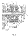
- Fig. 3 is an enlarged sectional view of the first clutch CL1 and the second clutch CL2.
- the transmission 21 has the six pairs of shift gears between the main shaft and the counter shaft, and the shift gear pair through which a rotational drive force is to be output can be selected according to the position of the slidable gears axially slidably mounted on the main shaft and the counter shaft and the engaged condition of the first clutch CL1 and the second clutch CL2.
- the twin clutch composed of the first clutch CL1 and the second clutch CL2 is provided in a clutch case 14 rotating with the primary driven gear 32.
- the first clutch CL1 is nonrotatably mounted on the inner main shaft 26a
- the second clutch CL2 is nonrotatably mounted on the outer main shaft 26b.
- a plurality of clutch disks B1 are provided between the clutch case 14 and the first clutch CL1, and a plurality of clutch disks B2 are provided between the clutch case 14 and the second clutch CL2.
- the clutch disks B1 are composed of four driving friction disks nonrotatably supported to the clutch case 14 and four driven friction disks nonrotatably supported to the first clutch CL1.
- the clutch disks B2 are composed of four driving friction disks nonrotatably supported to the clutch case 14 and four driven friction disks nonrotatably supported to the second clutch CL2.
- Each of the first and second clutches CL1 and CL2 is configured in such a manner that when an oil pressure is supplied from the hydraulic pump 41 to the clutch, a frictional force is produced between the clutch disks to achieve the engagement of the clutch.
- a distributor 8 forming two oil passages having a double pipe structure in the inner main shaft 26a is embedded in the wall of a clutch cover mounted on a crankcase.
- a clutch piston A1 is slid leftward as viewed in Fig. 3 against a biasing force of a return spring 12 as an elastic member, thereby achieving the engagement of the first clutch CL1.
- Fig. 4 is a block diagram showing the configuration of the AMT control unit 18 and its peripheral equipment according to this preferred embodiment.
- the AMT control unit 18 includes a shift control section 100 storing a shift map 101.
- the shift control section 100 including clutch control means drives the shift control motor 25 and the valve 42 (42a or 42b) by using the shift map 101 such as a three-dimensional map according to output information from the gear position sensor 38, the engine speed sensor 36, and the throttle angle sensor 47 and vehicle speed information from a vehicle speed sensor (not shown) during normal running of the vehicle, thus performing a shift operation.
- the shift control section 100 functions also as shift condition detecting means for detecting a shift condition such as a condition where the AMT 16 is being shifted according to a shift signal generated in the automatic shifting mode using the shift map 101 or in the semiautomatic shifting mode by the operation of the shift select switch 50.
- the condition where the AMT 16 is being shifted may be detected according to the output signals from the gear position sensor 38 and the engine speed sensor 36.
- the AMT 16 (see Fig. 1 ) according to this preferred embodiment is configured in such a manner that an oil pressure is supplied to the clutch by driving the actuator (valve) to thereby drive the clutch in its engaging direction against the biasing force of the corresponding return spring 12 (see Fig. 3 ). Accordingly, if the clutch disks wear to cause an increase in stroke of the clutch disks until they come into contact with each other or the return spring is replaced by another return spring having a larger biasing force, a load required to make the clutch disks come into contact with each other (return spring work load) is increased.
- the AMT control unit 18 can detect the load at the time the clutch disks come into contact with each other, i.e., at the time the clutch reaches "a stroke end position" such that the stroke of the clutch disks becomes a maximum value and can calculate a control correction amount for the clutch according to a change in this load.
- the work load can be obtained according to an oil pressure supplied to the clutch.
- the AMT control unit 18 includes oil pressure detecting means 150 for detecting the oil pressures generated in the first and second clutches CL1 and CL2 according to the output signals from the first and second clutch oil pressure sensors 75 and 76.
- the oil pressure detecting means 150 also inputs the drive signals for the first and second valves 42a and 42b from the shift control section 100 and can estimate the oil pressures generated in the clutches CL1 and CL2 from the drive control amounts for the first and second valves 42a and 42b.
- the AMT control unit 18 further includes stroke end detecting means 140 for detecting that the clutch has reached the stroke end position according to the oil pressure detected by the oil pressure detecting means 150.
- the AMT control unit 18 further includes clutch control correction amount calculating means 130 having stroke end spring work load calculating means 120 for calculating the return spring work load according to the oil pressure detected at the time the clutch has reached the stroke end position.
- Fig. 5 is a graph showing a change in clutch oil pressure in driving the clutch in its engaging direction.
- the broken line A shows a target oil pressure
- the solid line B shows an actual oil pressure detected by the oil pressure detecting means 150.
- the hydraulic clutch according to this preferred embodiment is configured in such a manner that when an oil pressure is supplied to the clutch, the clutch is driven in its engaging direction. Accordingly, immediately after opening the valve at the time t0 to engage the clutch, the clutch disks are moved toward each other, so that the actual oil pressure B is not increased at once. However, the actual oil pressure B is rapidly increased at the time t1 as shown in an encircled area in Fig. 5 . Thereafter, the actual oil pressure B becomes larger than the target oil pressure A and thereafter converges to the target oil pressure A.
- Such a rapid increase in the actual oil pressure B at the time t1 is caused by the fact that the clutch disks have come into contact with each other, i.e., the clutch has reached the stroke end position such that the stroke of the clutch disks is a maximum value. Accordingly, by observing a change in the actual oil pressure B, it is possible to estimate that the clutch has reached the stroke end position.
- the amount of change in the actual oil pressure B is obtained from the differential value thereof, and when this amount of change becomes larger than a predetermined value, it is determined that the clutch has reached the stroke end position.
- the amount of change in the actual oil pressure B at the time t1 is larger than a predetermined value, so that an oil pressure P1 detected at the time t1 is detected as the oil pressure at the stroke end position.
- the stroke end spring work load calculating means 120 calculates an actual return spring work load (actual work load) actually generated at the stroke end position by multiplying the oil pressure detected at the stroke end position by the pressure receiving area of the clutch piston (see Fig. 3 ) in calculating the clutch control correction amount.
- the actual work load is larger than a reference value, it is estimated that the clutch disks are worn to cause an increase in stroke and accordingly cause an increase in operational amount of the return spring or that the return spring has been replaced by another return spring having a larger biasing force.
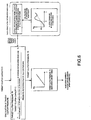
- Fig. 6 is a block diagram showing the procedure of calculating a clutch control correction amount according to an oil pressure detected at the stroke end position.
- the processing for calculating the control correction amount is performed by the clutch control correction amount calculating means 130.
- a target clutch pressure Pt to be generated in each clutch is calculated by the expression of [ ⁇ C/( ⁇ h ⁇ n ⁇ r) + F0 ⁇ /S], where C is the target clutch capacity, ⁇ h is the corrected friction coefficient, n is the number of clutch disks, r is the effective radius, F0 is the reference return spring work load, and S is the pressure receiving area of the clutch piston.
- the reference return spring work load (reference work load) F0 is a fixed value predetermined according to a design value or the like. According to this preferred embodiment, an actual return spring work load (actual work load) F actually generated in the clutch is detected according to a clutch oil pressure, and the target clutch pressure Pt is calculated by using this actual work load F.
- the oil pressure P1 is measured at the time the amount of change in actual oil pressure becomes larger than a predetermined value.
- the actual return spring work load F is calculated by multiplying this oil pressure P1 by the pressure receiving area S of the clutch piston. This actual work load F is used in place of the reference work load F0 to calculate the target clutch pressure Pt.
- the target clutch pressure Pt thus obtained in consideration of the change in condition or the like of the return spring is applied to a data table defining the relation between target clutch pressure Pt and valve drive current I, thereby obtaining a valve (actuator) drive current I for the correction control of the clutch, i.e., a clutch control amount after corrected in consideration of the actual work load.
- the clutch control correction amount calculating means 130 recognizes the difference between the clutch control amount before corrected and the clutch control amount after corrected and always monitors a change in this difference.
- the clutch control correction amount calculating means 130 controls the operation of the first and second clutches CL1 and CL2 by using the valve drive current I calculated above. Accordingly, even when there occurs a change in condition of the clutch due to a change in characteristics of the return spring, a change in running feel can be prevented.
- the clutch control amount calculation processing using the actual work load may be performed at the time of vehicle inspection or the like. Accordingly, even when there are variations in accuracy of the return spring, it is possible to make uniform the initial clutch settings prior to shipment of all vehicles from a factory.
- the clutch control correction amount calculating means 130 is connected to warning means 200 such as a warning lamp or a speaker for giving a warning to the operator when the clutch correction control amount becomes larger than a predetermined value. Accordingly, it is possible to urge the operator to replace the clutch disks or the return spring or to inspect a drive power transmitting system from the clutch to the drive wheel, for example.
- Fig. 7 is a flowchart showing the flow of clutch control correction amount calculation processing according to this preferred embodiment.
- the oil pressure detecting means 150 starts detecting the oil pressures generated in the first and second clutches CL1 and CL2.
- the first clutch CL1 or the second clutch CL2 subjected to the control correction amount calculation processing starts to be driven in its engaging direction.
- the control correction amount calculation processing i.e., the calculation processing for the clutch control amount after corrected may be performed alternately for the first and second clutches CL1 and CL2.
- the control correction amount calculation processing may be performed for any disengaged one of the clutches CL1 and CL2.
- step S3 it is determined whether or not the rate of change in clutch oil pressure has become larger than a predetermined value. If the answer in step S3 is affirmative, it is determined that the clutch has reached the stroke end position and the program then proceeds to step S4. If the answer in step S3 is negative, it is determined that the clutch has not yet reached the stroke end position and the program then proceeds to step S5 to continue to drive the clutch. Thereafter, the program returns to step S3.
- step S4 the clutch control correction amount calculating means 130 stores the oil pressure measured at the time the rate of change in clutch oil pressure has become larger than the predetermined value, i.e., at the time the clutch has reached the stroke end position.
- step S6 it is determined whether or not the temperature of the hydraulic fluid in the clutch detected by an oil temperature sensor (not shown) is less than or equal to a predetermined value (e.g., 50°C). The determination in step S6 is performed because the measured value for the oil pressure is influenced by a change in viscosity of the hydraulic fluid. If the answer in step S6 is affirmative, it is determined that the temperature of the hydraulic fluid is low and its viscosity is therefore high.
- step S6 it is determined that the condition of the clutch is not suitable for the calculation of the clutch control correction amount, and the program is accordingly ended.
- step S6 it is determined that the temperature of the hydraulic fluid has become higher than the predetermined value to reach a clutch condition suitable for the calculation of the clutch control correction amount. Then, the program proceeds to step S7.
- step S7 the calculation processing shown in Fig. 6 is performed by using the oil pressure stored in step S4, thereby calculating a clutch control correction amount.
- step S8 it is determined whether or not the clutch control correction amount has become larger than a predetermined value. If the answer in step S8 is negative, the program is ended. If the answer in step S8 is affirmative, i.e., if the clutch control correction amount has become larger than the predetermined value, it is determined that the inspection of the clutch disks or the return spring is required and the program then proceeds to step S9 to operate the warning means 200 (see Fig. 4 ), thereby giving a warning to the operator. Then, the program is ended.
- the clutch control amount calculation processing mentioned above may be performed before starting the vehicle after starting the engine, in halting the vehicle, or during running the vehicle. Further, the clutch control correction amount calculation processing may be performed at given intervals (e.g., at intervals of several days), so as to reduce the burden on the processing.
- the stroke end detecting means detects that the clutch has reached the stroke end position according to the amount of change in oil pressure in driving the clutch in its engaging direction.
- the control correction amount calculating means calculates a work load generated in the return spring according to the oil pressure detected at the time the clutch has reached the stroke end position, and then calculates a clutch control correction amount according to the difference between the work load calculated above and a predetermined reference value. Accordingly, the work load on the return spring can be calculated according to the oil pressure supplied to the clutch without the need for any special load sensor or the like, thus obtaining the clutch control correction amount.
- the configuration of the clutches and the valves in the twin clutch type transmission and the reference value for the amount of change in oil pressure in determining the stroke end position are not limited to those described above in this preferred embodiment, but various modifications may be made.
- the clutch control device according to the present invention is applied to a twin clutch type transmission in this preferred embodiment, the present invention is applicable also to a single clutch type transmission. Further, the clutch control device according to the present invention is applicable not only to a motorcycle, but also to a three-wheel vehicle and a four-wheel vehicle, for example.
Claims (7)
- Dispositif de commande d'embrayage pour un embrayage hydraulique (CL1, CL2) pour la connexion et la déconnexion d'une force de propulsion rotationnelle d'un moteur (11) à une transmission (16) dans un véhicule, dans lequel des disques d'embrayage (B1, B2) sont mis en fonctionnement dans leur direction d'engagement contre une force d'orientation d'un ressort de rappel (12) par commande d'un actionneur (A1, A2), ledit dispositif de commande d'embrayage comprenant:des moyens de commande d'embrayage (100) pour commander ledit embrayage (CL1, CL2);des moyens de détection de fin de course (140) pour détecter le fait que ledit embrayage (CL1, CL2) a atteint une position de fin de course dans laquelle lesdits disques d'embrayage (B1, B2) sont en contact mutuel;des moyens de détection de pression d'huile (75, 76) pour la détection d'une pression d'huile fournie audit embrayage (CL1, CL2); caractérisé en ce que ledit dispositif de commande d'embrayage comprend en outre des moyens pour le calcul de la quantité de correction de commande (130) pour calculer une charge de travail générée dans ledit ressort de rappel (12) en fonction de la pression d'huile détectée au moment où ledit embrayage (CL1, CL2) a atteint ladite position de fin de course, et pour calculer une quantité de correction de commande pour ledit embrayage (CL1, CL2) en fonction de la différence entre ladite charge de travail calculée ci-dessus et une valeur de référence prédéterminée.
- Dispositif de commande d'embrayage selon la revendication 1, dans lequel, quand le taux de changement de ladite pression d'huile devient plus élevé qu'une valeur prédéterminée, ledit moyen de détection de fin de course (140) détermine que ledit embrayage (CL1, CL2) a atteint ladite position de fin de course.
- Dispositif de commande d'embrayage selon la revendication 1 ou 2, dans lequel ledit embrayage est d'un type d'embrayage double, composé d'un premier embrayage (CL1) et d'un deuxième embrayage (CL2) procurés sur un arbre principal (26), et les états engagés desdits premier et deuxième embrayages (CL1, CL2) sont alternativement commutés dans chaque opération de bascule pour transmettre ainsi la force de commande rotationnelle dudit moteur (11) à ladite transmission (16).
- Dispositif de commande d'embrayage selon l'une quelconque des revendications 1 à 3, dans lequel le calcul de ladite quantité de correction de commande par ledit moyen de calcul de la quantité de correction de commande (130) est effectué après que la température d'un fluide hydraulique pour la commande dudit embrayage (CL1, CL2) devient supérieure à une valeur prédéterminée.
- Dispositif de commande d'embrayage selon l'une quelconque des revendications 1 à 4, dans lequel le calcul de ladite quantité de correction de commande par ledit moyen de calcul de la quantité de correction de commande (130) est effectué à des intervalles définis.
- Dispositif de commande d'embrayage selon l'une quelconque des revendications 1 à 5, dans lequel lorsque la quantité de correction de commande pour ledit embrayage (CL1, CL2) devient supérieure à une valeur prédéterminée, un avertissement est fourni par un moyen d'avertissement (200).
- Procédé pour le calcul d'une quantité de correction de commande d'embrayage pour un embrayage hydraulique (CL1, CL2) pour la connexion et la déconnexion d'une force de propulsion rotationnelle d'un moteur (11) à une transmission (16) dans un véhicule, dans lequel des disques d'embrayage (B1, B2) sont mis en fonctionnement dans leur direction d'engagement contre une force d'orientation d'un ressort de rappel (12) par commande d'un actionneur (A1, A2), ledit procédé de calcul de la quantité de correction de commande d'embrayage comprenant les étapes de:détection de ce que ledit embrayage (CL1, CL2) a atteint une position de fin de course dans laquelle lesdits disques d'embrayage (B1, B2) sont en contact mutuel;calcul d'une charge de travail générée dans ledit ressort de rappel (12) en fonction d'une pression d'huile détectée au moment où ledit embrayage (CL1, CL2) a atteint ladite position de fin de course; etcalcul d'une quantité de correction de commande pour ledit embrayage (CL1, CL2) en fonction de la différence entre ladite charge de travail générée ci-dessus et une valeur de référence prédéterminée.
Applications Claiming Priority (1)
| Application Number | Priority Date | Filing Date | Title |
|---|---|---|---|
| JP2008223952A JP5153525B2 (ja) | 2008-09-01 | 2008-09-01 | クラッチ制御装置 |
Publications (2)
| Publication Number | Publication Date |
|---|---|
| EP2159440A1 EP2159440A1 (fr) | 2010-03-03 |
| EP2159440B1 true EP2159440B1 (fr) | 2012-09-19 |
Family
ID=41360252
Family Applications (1)
| Application Number | Title | Priority Date | Filing Date |
|---|---|---|---|
| EP09167315A Active EP2159440B1 (fr) | 2008-09-01 | 2009-08-06 | Dispositif de commande d'embrayage et procédé de calcul de la quantité de correction de commande d'embrayage |
Country Status (4)
| Country | Link |
|---|---|
| US (1) | US8406976B2 (fr) |
| EP (1) | EP2159440B1 (fr) |
| JP (1) | JP5153525B2 (fr) |
| ES (1) | ES2393437T3 (fr) |
Families Citing this family (16)
| Publication number | Priority date | Publication date | Assignee | Title |
|---|---|---|---|---|
| GB2447507A (en) * | 2007-03-16 | 2008-09-17 | Cnh Belgium Nv | A method of engaging a clutch in an agricultural machine |
| JP5190430B2 (ja) * | 2009-09-30 | 2013-04-24 | 本田技研工業株式会社 | 常時開放型クラッチ構造 |
| JP5620671B2 (ja) * | 2009-11-24 | 2014-11-05 | ヤマハ発動機株式会社 | 変速装置 |
| JP5340978B2 (ja) * | 2010-02-03 | 2013-11-13 | 本田技研工業株式会社 | 変速制御装置 |
| WO2011127886A1 (fr) * | 2010-04-12 | 2011-10-20 | Schaeffler Technologies Gmbh & Co. Kg | Procédé de commande d'un accouplement automatique |
| GB2481838B (en) * | 2010-07-08 | 2017-05-31 | Gm Global Tech Operations Llc | Hydraulic clutch and method for determining an adaptive clutch fill volume of the hydraulic clutch |
| WO2012142277A1 (fr) * | 2011-04-12 | 2012-10-18 | Chrysler Group Llc | Procédé permettant de déterminer la température d'un embrayage à huile |
| DE102012204929A1 (de) * | 2011-04-15 | 2012-10-18 | Schaeffler Technologies AG & Co. KG | Verfahren zur Inbetriebnahme einer Kupplung |
| DE112012001718B4 (de) | 2011-04-15 | 2021-11-04 | Schaeffler Technologies AG & Co. KG | Verfahren zur Adaption von Parametern einer Kupplung |
| US8831844B2 (en) * | 2012-07-27 | 2014-09-09 | GM Global Technology Operations LLC | Clutch return spring pressure learning during a coasting maneuver |
| WO2014045357A1 (fr) * | 2012-09-19 | 2014-03-27 | ヤマハ発動機株式会社 | Dispositif de commande de véhicule, véhicule et moteur |
| EP3014136B1 (fr) * | 2013-06-27 | 2018-05-30 | Volvo Truck Corporation | Étalonnage d'embrayage automatique |
| DE102016203370A1 (de) * | 2015-03-17 | 2016-09-22 | Schaeffler Technologies AG & Co. KG | Verfahren zur Adaption eines Tastpunktes einer im unbetätigten Zustand geschlossenen Kupplung |
| US9478075B1 (en) * | 2015-04-15 | 2016-10-25 | Grant TOUTANT | Vehicle safety-inspection apparatus |
| US11009091B2 (en) * | 2016-09-23 | 2021-05-18 | Eaton Intelligent Power Limited | Clutch wear-out |
| US10647321B2 (en) * | 2016-12-22 | 2020-05-12 | Eaton Cummins Automated Transmission Technologies | High efficiency, high output transmission |
Family Cites Families (21)
| Publication number | Priority date | Publication date | Assignee | Title |
|---|---|---|---|---|
| US3968732A (en) * | 1972-11-10 | 1976-07-13 | Fitzgerald William Maurice Bar | Hydraulic power transmission system |
| JPS6084465A (ja) * | 1983-10-17 | 1985-05-13 | Honda Motor Co Ltd | 車両用自動変速機における流体伝動装置の直結制御装置 |
| JPS62155338A (ja) * | 1985-12-27 | 1987-07-10 | Aisin Warner Ltd | 摩擦係合装置のトルク容量の初期植自動設定方式 |
| JP3041163B2 (ja) * | 1993-06-03 | 2000-05-15 | トヨタ自動車株式会社 | 自動変速機の変速制御装置 |
| FR2796435B1 (fr) * | 1999-07-12 | 2008-08-01 | Luk Getriebe Systeme Gmbh | Entrainement de generation d'un deplacement relatif de deux composants |
| JP3519030B2 (ja) * | 1999-12-09 | 2004-04-12 | 本田技研工業株式会社 | 自動変速機の制御装置 |
| JP2003214467A (ja) * | 2002-01-24 | 2003-07-30 | Hitachi Constr Mach Co Ltd | 油圧ブレーキ装置、油圧クラッチ装置、およびこのブレーキ装置、クラッチ装置を備えたクレーンの巻上装置 |
| DE10390914D2 (de) * | 2002-03-07 | 2005-05-19 | Luk Lamellen & Kupplungsbau | Doppelkupplungsgetriebe und Verfahren zum Durchführen einer Schaltung bei einem Doppelkupplungsgetriebe |
| DE10316419B4 (de) * | 2002-04-10 | 2015-09-17 | Schaeffler Technologies AG & Co. KG | Verfahren zur Erkennung einer Leckage eines hydraulischen Ausrücksystems einer Doppelkupplung eines Parallelschaltgetriebes |
| WO2004036077A1 (fr) * | 2002-10-16 | 2004-04-29 | Luk Lamellen Und Kupplungsbau Beteiligungs Kg | Procede de detection de l'usure et/ou de reglage d'un embrayage double |
| JP2004197842A (ja) | 2002-12-18 | 2004-07-15 | Aisin Seiki Co Ltd | クラッチ制御装置 |
| JP4383045B2 (ja) * | 2002-12-27 | 2009-12-16 | アイシン・エィ・ダブリュ株式会社 | パワートレインの検査システム |
| JP4185878B2 (ja) * | 2004-03-31 | 2008-11-26 | ジヤトコ株式会社 | 自動変速機の制御装置 |
| DE102005019042A1 (de) * | 2004-05-05 | 2005-11-24 | Luk Lamellen Und Kupplungsbau Beteiligungs Kg | Verfahren zum Erkennen eines Fehlers einer Betätigungseinrichtung |
| JP4185922B2 (ja) * | 2005-06-03 | 2008-11-26 | ジヤトコ株式会社 | クラッチ制御装置及びクラッチ制御方法 |
| JP2007182977A (ja) * | 2006-01-10 | 2007-07-19 | Toyota Motor Corp | クラッチ式変速機の制御装置 |
| JP4699326B2 (ja) * | 2006-09-29 | 2011-06-08 | 本田技研工業株式会社 | ツインクラッチ装置 |
| JP4605169B2 (ja) * | 2007-03-20 | 2011-01-05 | 日産自動車株式会社 | クラッチ制御装置及びクラッチ制御方法 |
| JP4696105B2 (ja) * | 2007-11-30 | 2011-06-08 | 本田技研工業株式会社 | 自動二輪車のクラッチ制御装置 |
| JP5200272B2 (ja) * | 2008-05-27 | 2013-06-05 | 本田技研工業株式会社 | クラッチ制御装置 |
| JP5645414B2 (ja) * | 2010-02-03 | 2014-12-24 | 本田技研工業株式会社 | クラッチ制御装置 |
-
2008
- 2008-09-01 JP JP2008223952A patent/JP5153525B2/ja active Active
-
2009
- 2009-08-06 EP EP09167315A patent/EP2159440B1/fr active Active
- 2009-08-06 ES ES09167315T patent/ES2393437T3/es active Active
- 2009-08-19 US US12/461,646 patent/US8406976B2/en active Active
Also Published As
| Publication number | Publication date |
|---|---|
| EP2159440A1 (fr) | 2010-03-03 |
| JP5153525B2 (ja) | 2013-02-27 |
| JP2010059995A (ja) | 2010-03-18 |
| US8406976B2 (en) | 2013-03-26 |
| ES2393437T3 (es) | 2012-12-21 |
| US20100057318A1 (en) | 2010-03-04 |
Similar Documents
| Publication | Publication Date | Title |
|---|---|---|
| EP2159440B1 (fr) | Dispositif de commande d'embrayage et procédé de calcul de la quantité de correction de commande d'embrayage | |
| EP2128472B1 (fr) | Dispositif de commande d'embrayage | |
| JP5374726B2 (ja) | クラッチ制御装置およびμ補正係数算出方法 | |
| EP2532913B1 (fr) | Dispositif de commande d'embrayage | |
| EP2075492B1 (fr) | Dispositif de commande de changement de vitesse avec un embrayage double | |
| EP1816376B1 (fr) | Dispositif et procédé de contrôle pour véhicule | |
| CN101451594B (zh) | 换挡控制系统 | |
| EP2068047B1 (fr) | Système de commande de vitesse | |
| US20080006029A1 (en) | Hydraulic pressure control apparatus | |
| US8874333B2 (en) | Control apparatus for automatic transmission | |
| EP2063151B1 (fr) | Appareil de commande de vitesse automatique pour comportement anormal d'une transmission manuelle automatisée | |
| US8833191B2 (en) | Control apparatus for automatic transmission | |
| US20130261912A1 (en) | Control device for dual clutch transmission and control method for dual clutch transmission | |
| JP4934859B2 (ja) | 変速機のクラッチ制御装置 | |
| JP5512336B2 (ja) | 自動変速機の制御装置 | |
| US20100250078A1 (en) | Transmission and method of shift control for transmission | |
| US9841099B2 (en) | Automatic transmission control apparatus | |
| JP2010169210A (ja) | 車両用変速機の制御装置 | |
| JP5947070B2 (ja) | 変速機の制御装置 | |
| JP2008190701A (ja) | 自動変速機の制御方法および制御装置 | |
| JP2018100737A (ja) | 摩擦締結要素の潤滑制御装置 | |
| PH12016000222A1 (en) | Transmission and clutch control device |
Legal Events
| Date | Code | Title | Description |
|---|---|---|---|
| PUAI | Public reference made under article 153(3) epc to a published international application that has entered the european phase |
Free format text: ORIGINAL CODE: 0009012 |
|
| AK | Designated contracting states |
Kind code of ref document: A1 Designated state(s): AT BE BG CH CY CZ DE DK EE ES FI FR GB GR HR HU IE IS IT LI LT LU LV MC MK MT NL NO PL PT RO SE SI SK SM TR |
|
| AX | Request for extension of the european patent |
Extension state: AL BA RS |
|
| 17P | Request for examination filed |
Effective date: 20100728 |
|
| GRAP | Despatch of communication of intention to grant a patent |
Free format text: ORIGINAL CODE: EPIDOSNIGR1 |
|
| GRAS | Grant fee paid |
Free format text: ORIGINAL CODE: EPIDOSNIGR3 |
|
| GRAA | (expected) grant |
Free format text: ORIGINAL CODE: 0009210 |
|
| AK | Designated contracting states |
Kind code of ref document: B1 Designated state(s): AT BE BG CH CY CZ DE DK EE ES FI FR GB GR HR HU IE IS IT LI LT LU LV MC MK MT NL NO PL PT RO SE SI SK SM TR |
|
| REG | Reference to a national code |
Ref country code: GB Ref legal event code: FG4D |
|
| REG | Reference to a national code |
Ref country code: CH Ref legal event code: EP |
|
| REG | Reference to a national code |
Ref country code: IE Ref legal event code: FG4D |
|
| REG | Reference to a national code |
Ref country code: AT Ref legal event code: REF Ref document number: 576194 Country of ref document: AT Kind code of ref document: T Effective date: 20121015 |
|
| REG | Reference to a national code |
Ref country code: DE Ref legal event code: R096 Ref document number: 602009009767 Country of ref document: DE Effective date: 20121115 |
|
| REG | Reference to a national code |
Ref country code: ES Ref legal event code: FG2A Ref document number: 2393437 Country of ref document: ES Kind code of ref document: T3 Effective date: 20121221 |
|
| PG25 | Lapsed in a contracting state [announced via postgrant information from national office to epo] |
Ref country code: FI Free format text: LAPSE BECAUSE OF FAILURE TO SUBMIT A TRANSLATION OF THE DESCRIPTION OR TO PAY THE FEE WITHIN THE PRESCRIBED TIME-LIMIT Effective date: 20120919 Ref country code: HR Free format text: LAPSE BECAUSE OF FAILURE TO SUBMIT A TRANSLATION OF THE DESCRIPTION OR TO PAY THE FEE WITHIN THE PRESCRIBED TIME-LIMIT Effective date: 20120919 Ref country code: CY Free format text: LAPSE BECAUSE OF FAILURE TO SUBMIT A TRANSLATION OF THE DESCRIPTION OR TO PAY THE FEE WITHIN THE PRESCRIBED TIME-LIMIT Effective date: 20120919 Ref country code: LT Free format text: LAPSE BECAUSE OF FAILURE TO SUBMIT A TRANSLATION OF THE DESCRIPTION OR TO PAY THE FEE WITHIN THE PRESCRIBED TIME-LIMIT Effective date: 20120919 Ref country code: NO Free format text: LAPSE BECAUSE OF FAILURE TO SUBMIT A TRANSLATION OF THE DESCRIPTION OR TO PAY THE FEE WITHIN THE PRESCRIBED TIME-LIMIT Effective date: 20121219 |
|
| REG | Reference to a national code |
Ref country code: NL Ref legal event code: VDEP Effective date: 20120919 |
|
| REG | Reference to a national code |
Ref country code: AT Ref legal event code: MK05 Ref document number: 576194 Country of ref document: AT Kind code of ref document: T Effective date: 20120919 |
|
| REG | Reference to a national code |
Ref country code: LT Ref legal event code: MG4D Effective date: 20120919 |
|
| PG25 | Lapsed in a contracting state [announced via postgrant information from national office to epo] |
Ref country code: SE Free format text: LAPSE BECAUSE OF FAILURE TO SUBMIT A TRANSLATION OF THE DESCRIPTION OR TO PAY THE FEE WITHIN THE PRESCRIBED TIME-LIMIT Effective date: 20120919 Ref country code: SI Free format text: LAPSE BECAUSE OF FAILURE TO SUBMIT A TRANSLATION OF THE DESCRIPTION OR TO PAY THE FEE WITHIN THE PRESCRIBED TIME-LIMIT Effective date: 20120919 Ref country code: LV Free format text: LAPSE BECAUSE OF FAILURE TO SUBMIT A TRANSLATION OF THE DESCRIPTION OR TO PAY THE FEE WITHIN THE PRESCRIBED TIME-LIMIT Effective date: 20120919 Ref country code: GR Free format text: LAPSE BECAUSE OF FAILURE TO SUBMIT A TRANSLATION OF THE DESCRIPTION OR TO PAY THE FEE WITHIN THE PRESCRIBED TIME-LIMIT Effective date: 20121220 |
|
| PG25 | Lapsed in a contracting state [announced via postgrant information from national office to epo] |
Ref country code: EE Free format text: LAPSE BECAUSE OF FAILURE TO SUBMIT A TRANSLATION OF THE DESCRIPTION OR TO PAY THE FEE WITHIN THE PRESCRIBED TIME-LIMIT Effective date: 20120919 Ref country code: RO Free format text: LAPSE BECAUSE OF FAILURE TO SUBMIT A TRANSLATION OF THE DESCRIPTION OR TO PAY THE FEE WITHIN THE PRESCRIBED TIME-LIMIT Effective date: 20120919 Ref country code: NL Free format text: LAPSE BECAUSE OF FAILURE TO SUBMIT A TRANSLATION OF THE DESCRIPTION OR TO PAY THE FEE WITHIN THE PRESCRIBED TIME-LIMIT Effective date: 20120919 Ref country code: CZ Free format text: LAPSE BECAUSE OF FAILURE TO SUBMIT A TRANSLATION OF THE DESCRIPTION OR TO PAY THE FEE WITHIN THE PRESCRIBED TIME-LIMIT Effective date: 20120919 Ref country code: BE Free format text: LAPSE BECAUSE OF FAILURE TO SUBMIT A TRANSLATION OF THE DESCRIPTION OR TO PAY THE FEE WITHIN THE PRESCRIBED TIME-LIMIT Effective date: 20120919 Ref country code: IS Free format text: LAPSE BECAUSE OF FAILURE TO SUBMIT A TRANSLATION OF THE DESCRIPTION OR TO PAY THE FEE WITHIN THE PRESCRIBED TIME-LIMIT Effective date: 20130119 |
|
| PG25 | Lapsed in a contracting state [announced via postgrant information from national office to epo] |
Ref country code: SK Free format text: LAPSE BECAUSE OF FAILURE TO SUBMIT A TRANSLATION OF THE DESCRIPTION OR TO PAY THE FEE WITHIN THE PRESCRIBED TIME-LIMIT Effective date: 20120919 Ref country code: PT Free format text: LAPSE BECAUSE OF FAILURE TO SUBMIT A TRANSLATION OF THE DESCRIPTION OR TO PAY THE FEE WITHIN THE PRESCRIBED TIME-LIMIT Effective date: 20130121 Ref country code: PL Free format text: LAPSE BECAUSE OF FAILURE TO SUBMIT A TRANSLATION OF THE DESCRIPTION OR TO PAY THE FEE WITHIN THE PRESCRIBED TIME-LIMIT Effective date: 20120919 |
|
| PG25 | Lapsed in a contracting state [announced via postgrant information from national office to epo] |
Ref country code: AT Free format text: LAPSE BECAUSE OF FAILURE TO SUBMIT A TRANSLATION OF THE DESCRIPTION OR TO PAY THE FEE WITHIN THE PRESCRIBED TIME-LIMIT Effective date: 20120919 |
|
| PLBE | No opposition filed within time limit |
Free format text: ORIGINAL CODE: 0009261 |
|
| STAA | Information on the status of an ep patent application or granted ep patent |
Free format text: STATUS: NO OPPOSITION FILED WITHIN TIME LIMIT |
|
| PG25 | Lapsed in a contracting state [announced via postgrant information from national office to epo] |
Ref country code: BG Free format text: LAPSE BECAUSE OF FAILURE TO SUBMIT A TRANSLATION OF THE DESCRIPTION OR TO PAY THE FEE WITHIN THE PRESCRIBED TIME-LIMIT Effective date: 20121219 Ref country code: DK Free format text: LAPSE BECAUSE OF FAILURE TO SUBMIT A TRANSLATION OF THE DESCRIPTION OR TO PAY THE FEE WITHIN THE PRESCRIBED TIME-LIMIT Effective date: 20120919 |
|
| 26N | No opposition filed |
Effective date: 20130620 |
|
| REG | Reference to a national code |
Ref country code: DE Ref legal event code: R097 Ref document number: 602009009767 Country of ref document: DE Effective date: 20130620 |
|
| REG | Reference to a national code |
Ref country code: CH Ref legal event code: PL |
|
| GBPC | Gb: european patent ceased through non-payment of renewal fee |
Effective date: 20130806 |
|
| PG25 | Lapsed in a contracting state [announced via postgrant information from national office to epo] |
Ref country code: LI Free format text: LAPSE BECAUSE OF NON-PAYMENT OF DUE FEES Effective date: 20130831 Ref country code: MC Free format text: LAPSE BECAUSE OF FAILURE TO SUBMIT A TRANSLATION OF THE DESCRIPTION OR TO PAY THE FEE WITHIN THE PRESCRIBED TIME-LIMIT Effective date: 20120919 Ref country code: CH Free format text: LAPSE BECAUSE OF NON-PAYMENT OF DUE FEES Effective date: 20130831 |
|
| REG | Reference to a national code |
Ref country code: IE Ref legal event code: MM4A |
|
| REG | Reference to a national code |
Ref country code: FR Ref legal event code: ST Effective date: 20140430 |
|
| PG25 | Lapsed in a contracting state [announced via postgrant information from national office to epo] |
Ref country code: IE Free format text: LAPSE BECAUSE OF NON-PAYMENT OF DUE FEES Effective date: 20130806 Ref country code: GB Free format text: LAPSE BECAUSE OF NON-PAYMENT OF DUE FEES Effective date: 20130806 |
|
| PG25 | Lapsed in a contracting state [announced via postgrant information from national office to epo] |
Ref country code: FR Free format text: LAPSE BECAUSE OF NON-PAYMENT OF DUE FEES Effective date: 20130902 |
|
| REG | Reference to a national code |
Ref country code: DE Ref legal event code: R084 Ref document number: 602009009767 Country of ref document: DE |
|
| PG25 | Lapsed in a contracting state [announced via postgrant information from national office to epo] |
Ref country code: SM Free format text: LAPSE BECAUSE OF FAILURE TO SUBMIT A TRANSLATION OF THE DESCRIPTION OR TO PAY THE FEE WITHIN THE PRESCRIBED TIME-LIMIT Effective date: 20120919 |
|
| PG25 | Lapsed in a contracting state [announced via postgrant information from national office to epo] |
Ref country code: TR Free format text: LAPSE BECAUSE OF FAILURE TO SUBMIT A TRANSLATION OF THE DESCRIPTION OR TO PAY THE FEE WITHIN THE PRESCRIBED TIME-LIMIT Effective date: 20120919 Ref country code: MT Free format text: LAPSE BECAUSE OF FAILURE TO SUBMIT A TRANSLATION OF THE DESCRIPTION OR TO PAY THE FEE WITHIN THE PRESCRIBED TIME-LIMIT Effective date: 20120919 |
|
| PG25 | Lapsed in a contracting state [announced via postgrant information from national office to epo] |
Ref country code: LU Free format text: LAPSE BECAUSE OF NON-PAYMENT OF DUE FEES Effective date: 20130806 Ref country code: HU Free format text: LAPSE BECAUSE OF FAILURE TO SUBMIT A TRANSLATION OF THE DESCRIPTION OR TO PAY THE FEE WITHIN THE PRESCRIBED TIME-LIMIT; INVALID AB INITIO Effective date: 20090806 Ref country code: MK Free format text: LAPSE BECAUSE OF FAILURE TO SUBMIT A TRANSLATION OF THE DESCRIPTION OR TO PAY THE FEE WITHIN THE PRESCRIBED TIME-LIMIT Effective date: 20120919 |
|
| REG | Reference to a national code |
Ref country code: DE Ref legal event code: R085 Ref document number: 602009009767 Country of ref document: DE |
|
| PGFP | Annual fee paid to national office [announced via postgrant information from national office to epo] |
Ref country code: ES Payment date: 20190902 Year of fee payment: 11 |
|
| PGFP | Annual fee paid to national office [announced via postgrant information from national office to epo] |
Ref country code: IT Payment date: 20200713 Year of fee payment: 12 |
|
| REG | Reference to a national code |
Ref country code: ES Ref legal event code: FD2A Effective date: 20220110 |
|
| PG25 | Lapsed in a contracting state [announced via postgrant information from national office to epo] |
Ref country code: ES Free format text: LAPSE BECAUSE OF NON-PAYMENT OF DUE FEES Effective date: 20200807 |
|
| PG25 | Lapsed in a contracting state [announced via postgrant information from national office to epo] |
Ref country code: IT Free format text: LAPSE BECAUSE OF NON-PAYMENT OF DUE FEES Effective date: 20210806 |
|
| PGFP | Annual fee paid to national office [announced via postgrant information from national office to epo] |
Ref country code: DE Payment date: 20230613 Year of fee payment: 15 |