EP2159346A2 - Slab laying mat - Google Patents
Slab laying mat Download PDFInfo
- Publication number
- EP2159346A2 EP2159346A2 EP09168136A EP09168136A EP2159346A2 EP 2159346 A2 EP2159346 A2 EP 2159346A2 EP 09168136 A EP09168136 A EP 09168136A EP 09168136 A EP09168136 A EP 09168136A EP 2159346 A2 EP2159346 A2 EP 2159346A2
- Authority
- EP
- European Patent Office
- Prior art keywords
- tile
- layer
- laying mat
- tile laying
- moisture
- Prior art date
- Legal status (The legal status is an assumption and is not a legal conclusion. Google has not performed a legal analysis and makes no representation as to the accuracy of the status listed.)
- Withdrawn
Links
Images
Classifications
-
- E—FIXED CONSTRUCTIONS
- E04—BUILDING
- E04F—FINISHING WORK ON BUILDINGS, e.g. STAIRS, FLOORS
- E04F15/00—Flooring
- E04F15/18—Separately-laid insulating layers; Other additional insulating measures; Floating floors
- E04F15/182—Underlayers coated with adhesive or mortar to receive the flooring
-
- E—FIXED CONSTRUCTIONS
- E04—BUILDING
- E04F—FINISHING WORK ON BUILDINGS, e.g. STAIRS, FLOORS
- E04F15/00—Flooring
- E04F15/18—Separately-laid insulating layers; Other additional insulating measures; Floating floors
- E04F15/185—Underlayers in the form of studded or ribbed plates
-
- E—FIXED CONSTRUCTIONS
- E04—BUILDING
- E04F—FINISHING WORK ON BUILDINGS, e.g. STAIRS, FLOORS
- E04F15/00—Flooring
- E04F15/18—Separately-laid insulating layers; Other additional insulating measures; Floating floors
- E04F15/186—Underlayers covered with a mesh or the like
-
- E—FIXED CONSTRUCTIONS
- E04—BUILDING
- E04F—FINISHING WORK ON BUILDINGS, e.g. STAIRS, FLOORS
- E04F15/00—Flooring
- E04F15/18—Separately-laid insulating layers; Other additional insulating measures; Floating floors
- E04F15/20—Separately-laid insulating layers; Other additional insulating measures; Floating floors for sound insulation
- E04F15/203—Separately-laid layers for sound insulation
-
- Y—GENERAL TAGGING OF NEW TECHNOLOGICAL DEVELOPMENTS; GENERAL TAGGING OF CROSS-SECTIONAL TECHNOLOGIES SPANNING OVER SEVERAL SECTIONS OF THE IPC; TECHNICAL SUBJECTS COVERED BY FORMER USPC CROSS-REFERENCE ART COLLECTIONS [XRACs] AND DIGESTS
- Y10—TECHNICAL SUBJECTS COVERED BY FORMER USPC
- Y10T—TECHNICAL SUBJECTS COVERED BY FORMER US CLASSIFICATION
- Y10T428/00—Stock material or miscellaneous articles
- Y10T428/24—Structurally defined web or sheet [e.g., overall dimension, etc.]
- Y10T428/24479—Structurally defined web or sheet [e.g., overall dimension, etc.] including variation in thickness
Definitions
- the present invention relates to a tile laying mat for laying tiles on a substrate.
- tiles is used below as a generic term for all hard coverings made of ceramic, natural stone or mineral bonded tiles and slabs as well as made of plastics or wood-based materials rigid lining material.
- the DE 37 01 414 A1 a tile laying mat with a plastic plate having a profile consisting of mutually parallel, alternating dovetailed webs and dovetailed grooves, and with a connected to the underside of the plastic plate attachment layer for securing the tile laying mat on a substrate, wherein the attachment layer is formed by a coarse-meshed nonwoven fabric ,
- the wall or floor surface to be covered with tiles is first coated with an adhesive or mortar layer. Then the tile laying mat is glued to the substrate with the aid of the coarse-mesh net fleece arranged on its underside.
- the directed to the ground side dovetailed grooves of the plastic plate which are only partially filled with adhesive or mortar, form pressure equalization spaces that compensate in the finished floor joint between the substrate and the tiles occurring stresses and serve to dissipate moisture from the substrate or the adhesive - or mortar layer rises to tile laying mat.
- another adhesive or mortar layer is applied to the top of the plastic plate, wherein the adhesive or the mortar clamped in the open to the upper side of the plastic plate dovetailed grooves. In this way, a firm hold in the dried state of the adhesive or mortar generated between the plastic plate and the adhesive or mortar layer. After applying the adhesive or mortar layer tiles can now be laid on top of the tile laying mat.
- a tile laying mat which has both a decoupling and a drainage function.
- a major disadvantage of this tile laying mat is that although rising from below towards the tile laying mat moisture can be collected and removed in the pressure compensation chambers formed by the dovetailed grooves of the plastic plate directed to the ground side, but not moisture in the adhesive or mortar layer between the Tile laying mat and the tiles is present. This is particularly a problem when very large, moisture-impermeable tiles are used, so that a removal of moisture through the existing joints between the tiles is not sufficient. Accordingly, the adhesive between the tile laying mat and the tiles can not dry sufficiently, which may lead to the tiles peeling off, depending on the type of glue used or the temperature variations experienced by the composite.
- tile laying mat is in the EP 1 712 695 A2 disclosed.
- This tile laying mat comprises a film-like plastic plate with respect to its top outstanding, load-bearing, hollow towards the bottom, arranged in a uniform surface distribution, partially undercut support elements, between the support elements open wasserabracede channels are formed.
- a water- and vapor-permeable non-woven or fabric-like cover is arranged on the support elements.
- the laying mat is embedded on the substrate over its entire surface in the area of its lower bearing surfaces in a still soft, thermosetting Dünnbettmörtel für, with the mortar anchored in the undercuts of the undercut trained support elements, creating a solid bond between the ground and the tile laying mat is produced.
- the ceramic plates are laid directly on a thin-bed mortar layer on the top of the tile laying mat arranged fleece-like cover and fixed, where the mortar is clamped to the fleece, so that the tiles are securely held on the tile laying mat.
- moisture present in the thin-bed mortar layer disposed between the tile-laying mat and the tiles can pass through the non-woven or fabric-like cover into the drainage channels and be discharged therefrom.
- moisture coming from below can not penetrate the film-like plastic plate, which is why removal of moisture from the substrate or from the thin-bed mortar layer arranged underneath the tile-laying mat is not possible.
- a tile laying mat of alternative construction is to be provided which allows two-sided removal of moisture even when using large-area, moisture-impermeable tiles.
- the tile laying mat according to the present invention is a moisture-permeable mat, that is to say a mat which, when installed as intended, allows water in the liquid and / or vapor state to be passed both from above and from below.
- a moisture-receiving layer having a thickness of at least 1 mm to ensure a sufficient moisture-absorbing volume.
- This moisture absorption layer is preferably not only moisture-permeable but also moisture-wicking and / or moisture-balancing. Accordingly, the moisture absorbed in it is evenly distributed and / or derived.
- the moisture absorption layer is preferably air-permeable and / or heat-insulating and / or sound-insulating.
- the moisture-absorbing layer also has a plurality of recesses extending from the upper side toward the lower side. These recesses, which are preferably distributed evenly over the entire surface of the tile laying mat are filled in the laying of the tiles with adhesive or mortar, whereby Tragstelzen are formed, which absorb those forces and forward to the ground, which are applied to the tiles.
- These support stilts also prevent the moisture absorption volume provided by the moisture-receiving layer from being reduced due to forces acting on the tiles. So they serve as spacers, which counteract a compression of the moisture absorption layer and accordingly ensure the proper moisture absorption function of the tile laying mat.
- the tile laying mat is to perform a decoupling function in addition to its moisture absorption function, then it is important that the recesses do not penetrate the underside of the tile laying mat.
- the recesses must therefore not form through holes. Accordingly, it is prevented that the supporting stilts formed by the recesses connect with the adhesive or mortar layer arranged below the tile laying mat and a direct coupling is produced.
- the load-bearing stilts can move within the recesses-possibly with displacement of adjacently arranged regions of the moisture absorption layer.
- the bottom and / or side walls of the recesses are advantageously at least partially formed such that there is no adhesive bond between them and a tile adhesive introduced into the recesses or the load-bearing stilts.
- the bottom and / or side walls of the recesses are in the form of a smooth plastic surface which forms an adhesive bond between the bottom and / or side walls of the recesses and the tile adhesive prevented.
- the moisture absorption layer is advantageously non-woven or fabric-like and has a corresponding elasticity. It preferably comprises the same or differently formed plastic threads, in particular polyester threads, which can be arranged regularly with a predetermined orientation and / or in the form of a fabric or irregularly as a tangle.
- the moisture absorption layer is preferably a fastening layer connected, in particular glued.
- the underside or upper side of the attachment layer is preferably designed such that it forms an adhesive bond with a tile adhesive.
- the attachment layer may be formed for this purpose a fleece, tissue or lattice-like. In this case, the attachment layer should prevent too deep penetration of the adhesive into the moisture absorption layer in order not to impair the function of the moisture absorption layer.
- the moisture-receiving layer is, in accordance with an embodiment of the present invention, a pile fabric layer of a spacer fabric disposed between a lower and an upper cover fabric layer.
- spacer fabrics are already known in the prior art in other contexts and are used in particular for the upholstery of objects, such as bicycle helmets, shoe soles or the like. They are mainly made of polyamides and polyester and offer a very good heat and moisture regulation due to the existing between the threads of such a knit cavities. These spacer fabrics can be produced in different thicknesses. For the present application, spacer fabrics having a thickness of 1 mm and more are preferred.
- the defined distance between the two cover textile layers of the spacer knitted fabric is normally achieved by the pressure-elastic threads (pile threads).
- the use of such spacer fabric as a carrier for ceramic plates thus ensures both a good drainage and thermal insulation function. Further, if desired, a decoupling function can be realized.
- the underside of the lower cover textile layer and / or the upper side of the upper cover textile layer is / are, according to one embodiment of the present invention, non-woven in order to achieve a good adhesive bond between the underside of the lower cover textile layer and an adhesive.
- a bonding layer in particular glued, the underside / top or the outwardly facing side is formed such that it with a tile adhesive an adhesive bond for fixing the tile laying mat is received.
- the outwardly facing side of the attachment layer is advantageously formed like a fleece to achieve the desired adhesive bond.
- the tile laying mat has a total thickness preferably in the range of 1-5 mm. Furthermore, it is advantageously designed so flexible that it can be rolled up. Of course, it can also have a greater thickness, for example, if a good air circulation in the attachment of tiles to wall or ceiling surfaces to be guaranteed.
- the tile laying mat is designed so tear-resistant that it can be fastened to walls and ceilings with fastening means, in particular with dowels and screws.
- the present invention provides a method for producing a tile laying mat of the type defined above.
- the method includes the step of forming the recesses of the moisture-receiving layer by partially fusing at least the moisture-receiving layer, thereby producing smooth bottom and / or side walls that prevent adhesive bonding to a tile adhesive.
- the recesses are advantageously formed using hot stamping dies of a molding tool in the tile laying mat.
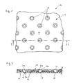
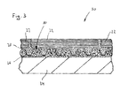
- FIGS. 1 to 3 show a tile laying mat 10 according to a first embodiment of the present invention, wherein the Figures 1 and 2 the tile laying mat 10 show itself, whereas the FIG. 3 in the Figures 1 and 2 illustrated tile laying mat 10 in the installed state represents.
- the tile laying mat 10 which may be plate, sheet or carpet-like, comprises a moisture-permeable, fleece-like moisture absorption layer 12.
- the moisture absorption layer 12 has a plurality of irregularly arranged in the manner of a tangle plastic threads, such as polyester threads, which are at least partially interconnected and Accordingly, create a coherent mat-like composite with a top 14 and a bottom 16.
- the moisture absorption layer also includes a plurality of recesses 18 extending from the top 14 towards the bottom 16, but not piercing the latter.
- the recesses 18 have a circular cross-section, which tapers conically from top to bottom, whereby upside-down truncated cone shapes are formed.
- These recesses 18 are made by pressing hot punches of a die, the ends of which have a negative contour corresponding to the contours of the recesses 18, into the top 14 of the moisture-receiving layer 12, the plastic threads contacting the punches due to the high temperature come to be melted, so that the recesses 18 arise. Due to the melting process of the plastic threads, the recesses 18 receive a smooth bottom wall 20a and a smooth side wall 20b.
- the thickness d of the moisture absorption layer 12 or the tile laying mat 10 is in the present case 3 mm. In principle, however, the thickness can be in a range between 1 and 5 mm. If, for example, a floor structure with a low height is in the foreground, then a small thickness d is recommended. If, on the other hand, a good insulation function is of particular importance, it is advisable to choose a larger thickness d.
- tile adhesive layer 26 For laying tiles 22 on a substrate 24, which may be a floor or a wall surface, is on the substrate 24, as in FIG. 3 is shown, first applied a tile adhesive layer 26. Subsequently, the tile laying mat 10 is pressed onto the tile adhesive layer 26 with the underside 16 of the moisture receiving layer 12, tile adhesive partially penetrating the interstices between the plastic threads of the moisture receiving layer 12 and enclosing the plastic threads, so that the moisture receiving layer 12 over the tile adhesive layer after drying of the adhesive 26 is firmly connected to the substrate 24. Subsequently, a further tile adhesive layer 28 is applied to the upper side 14 of the moisture absorption layer 12.
- the tile adhesive penetrates partially into the nonwoven on the upper side 14 of the moisture absorption layer 12, whereby after drying of the tile adhesive also a firm bond between the tile adhesive layer 28 and the moisture absorption layer is generated. Further the tile adhesive 28 applied to the upper side 14 of the moisture-receiving layer 12 penetrates into the recesses 18 and fills them completely. Due to the smooth bottom and side walls 20a, 20b of the recesses 18, however, unlike the top 14, no strong bond is created between the tile adhesive and the walls 20a, 20b of the recesses 18. In a subsequent step, the tiles 22 can now be placed on the tile adhesive layer 28, in order in this way the in FIG. 3 finished floor composite 30 completed.
- the moisture-receiving layer 12 of the tile-laying mat 10 is moisture-permeable, moisture present in the substrate 24 and in the lower tile adhesive layer 28 may enter the moisture-receiving layer 12 through the upper surface 16 as well as moisture present in the upper tile adhesive layer 28 , Accordingly, the substrate 24 as well as the tile adhesive layers 26 and 28 can easily completely dry out and harden, whereby the extracted moisture is collected in the moisture absorption layer 12 and possibly removed by it.
- the penetrating from above into the recesses 18 adhesive forms supporting stilts, which extend from the top 14 of the moisture receiving layer 12 in the direction of the bottom 16, the latter, however, do not break, with the support stilts compressing the underlying them fleece of the moisture absorption layer 12 against the ground Support 24 or tile adhesive 26. Accordingly, there is no direct connection between the upper adhesive layer 28 and the lower adhesive layer 26, so that the adhesive layers 26, 28 are decoupled from each other and thus the substrate 24 from the tiles 22. Due to the smooth bottom and side walls 20a, 20b of the recesses 18, the support stilts are also loosely received in the recesses 18, so they can move laterally with displacement of the adjacently arranged nonwoven moisture absorption layer 12. In this way, existing stresses between the substrate 24 and the tiles 22 can be compensated for and a loosening of the tiles 22 due to such stresses can be prevented.
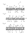
- FIG. 4 shows a cross-sectional view of a tile laying mat 40 according to a second embodiment of the present invention.
- the tile laying mat 40 comprises a moisture absorption layer 42 which is formed of plastic threads arranged transversely to each other.
- the moisture-receiving layer 42 comprises a regular, brush-like structure, which has a relatively high strength due to the orientation of the plastic threads. Accordingly, the moisture-receiving layer 42 is less likely to compress than, for example, the moisture-receiving layer 12 of FIG FIGS. 1 to 3
- the tile laying mat 40 further comprises two attachment layers 44 and 46 of nonwoven, which receive the moisture absorbing layer 42 between them and are each glued to this.
- the tile laying mat 40 further comprises analogous to FIG. 1 a plurality of recesses 48 each extending through the upper attachment layer 46 and the moisture-receiving layer 42. On the other hand, the recesses 48 do not pass through the lower attachment layer 44.
- the recesses 48 are analogous to FIG. 1 regularly distributed over the entire top of the tile laying mat 40 and have a circular cross-section gradually tapers from the upper attachment layer 46 in the direction of the lower attachment layer 46, as in FIG. 4 can be seen.
- the recesses 48 of the tile laying mat 40 smooth bottom walls 50a and smooth side walls 50b, whereby an adhesive bond between the walls 50a, 50b of the recesses 48 and a disposed in the recesses 48 tile adhesive is prevented.
- Tiles 22 on a substrate 24 below Use of the tile laying mat 40 are laid, where initially a tile adhesive layer 26 is applied to the substrate 24 again. Thereafter, the tile laying mat with the lower attachment layer 44 is pressed onto the tile adhesive layer 26, so that the tile adhesive at least partially penetrates into the fleece of the attachment layer 44 and surrounds it, so that in the cured state of the tile adhesive, a firm bond between the tile adhesive layer 26 and the attachment layer 44th is produced. Subsequently, a further tile adhesive layer 28 is applied to the top of the upper attachment layer 46 of the tile laying mat 40, wherein the tile adhesive partially penetrates into the web of the upper attachment layer 46 so that a correspondingly strong bond is also generated there.
- the tile adhesive penetrates into the recesses 48 of the tile laying mat 40 and fills them completely. Due to the smooth bottom and side walls 50a, 50b of the recesses 48, however, an adhesive bond between tile adhesive and the bottom and side walls 50a, 50b of the recesses 48 is prevented.
- FIG. 5 shows a cross-sectional view of a tile laying mat 60 according to a third embodiment of the present invention.
- the tile laying mat 60 includes a moisture-receiving layer 42 as previously described with reference to FIG FIG. 4 has been described.
- an intermediate layer 62 is further adhesively held.
- this intermediate layer is a moisture-permeable woven fabric layer which does not adhere to adhesive bond with tile adhesive when it comes into contact with it.
- a fastening layer 44 is fixed, as previously described with reference to the second embodiment.
- the tile laying mat 60 comprises a multiplicity of regularly distributed recesses 64 in an analogous manner FIG.
- These recesses 64 extend through the entire moisture absorption layer 42 and comprise a circular cross section which widens in the direction of the underside 16, starting from the upper side 14 of the moisture absorption layer 42, so that arise truncated cone shapes. Alternatively, for example, a truncated pyramidal formation or the like would be conceivable here as well.
- the recesses 64 viewed from above, form undercuts in which tile adhesives introduced into the recesses 64 can be clamped. Thus, on the in FIG. 4 omitted upper attachment layer can be omitted.
- the recesses 64 also have smooth bottom and side walls 66a, 66b which, together with the intermediate layer 62, prevent sticking of tile adhesive within the recesses 64.
- FIG. 6 shows a cross-sectional view of a tile laying mat 70 according to a fourth embodiment of the present invention.
- the tile laying mat 70 includes a moisture-receiving layer 42 as previously described with reference to FIG FIG. 4 has been described.
- a woven upper cover textile layer 72 and a woven lower cover textile layer 74 are fixedly bonded to the upper surface 14 and the lower surface 16 of the moisture receiving layer 42, so that the moisture absorption layer 42 is sandwiched between the cover textile layers 72 and 74 in a knit-knitted manner to form a so-called pile layer.
- the tile laying mat 70 further includes a plurality of recesses 66 analogous to FIG. 1 extending through the upper cover textile layer 72 and the moisture-receiving layer 42.
- the recesses 76 are cylindrically shaped and comprise smooth bottom and side walls 78a, 78b, which do not form an adhesive bond with tile adhesive. Also, the woven fabric cover layers 72 and 74 do not bond with tile adhesive. For this reason, a fastening layer 44 is attached to the lower cover layer 74, as described with reference to FIG FIG. 4 has already been explained in order to be able to stick the tile laying mat 70 to a substrate using a tile adhesive. Further, a mounting grid is glued to the upper decktextil slaughter 72, the mesh width is so large that applied to the tile laying mat 70 tile adhesive easily penetrate the mounting grid 80 and fill the recesses 76. This mounting grid 80 provides a firm adhesive bond between the Tile adhesive and the top of the tile laying mat 70 in order to produce in this way a proper floor joint can.
- the moisture-absorbing layers 12 and 42 of the tile-laying mats 10, 40, 60 and 70 of the embodiments described above are not only moisture-permeable but also moisture-wicking and moisture-compensating. In addition, they are permeable to air, heat-insulating and soundproofing.
- the moisture-receiving layers of the individual tile-laying mats may include not only plastic threads but also natural-material threads, metal threads, metal-sheathed metal threads, or the like. Also, combinations of filaments of different shapes and materials, such as open-cell foamed material, are possible. In addition, the recesses may have any cross-sectional shapes, such as polygonal, round or oval cross sections. Furthermore, the rigidity of the tile laying mat according to the invention in thickness direction is preferably selected such that the tile laying mat can at least absorb the weight of the adhesive layer arranged above it and the tiles, without any significant compression in Thickness direction to learn.
- the cavity provided by the moisture-receiving layer for absorbing moisture is prevented from being reduced during the drying of the adhesive due to the self-weight of the adhesive layer and the tiles.
- the support stilts prevent compression of the moisture-receiving layer.
- adheresive is meant all for the attachment of the tile laying mat and / or the attachment of the respective designated as tiles hard coverings suitable adhesives or mortars.
Abstract
Description
Die vorliegende Erfindung bezieht sich auf eine Fliesenverlegematte zum Verlegen von Fliesen auf einem Untergrund. Der Begriff Fliesen wird nachfolgend als Oberbegriff für sämtliche Hartbeläge aus Keramik, Naturstein oder mineralisch gebundene Fliesen und Platten sowie für aus Kunststoffen oder Holzwerkstoffen hergestelltes biegesteifes Belagmaterial verwendet.The present invention relates to a tile laying mat for laying tiles on a substrate. The term tiles is used below as a generic term for all hard coverings made of ceramic, natural stone or mineral bonded tiles and slabs as well as made of plastics or wood-based materials rigid lining material.
Fliesenverlegematten der zuvor genannten Art sind im Stand der Technik in unterschiedlichen Ausgestaltungen bekannt.Tile laying mats of the aforementioned type are known in the prior art in different embodiments.
Beispielsweise offenbart die
Mit der
Eine weitere Fliesenverlegematte ist in der
Ausgehend von diesem Stand der Technik ist es eine Aufgabe der vorliegenden Erfindung, eine Fliesenverlegematte mit alternativem Aufbau zu schaffen. Insbesondere soll eine Fliesenverlegematte bereitgestellt werden, die beidseitiges Abführen von Feuchtigkeit auch bei der Verwendung von großflächigen, feuchtigkeitsundurchlässigen Fliesen gestattet.Based on this prior art, it is an object of the present invention to provide a tile laying mat of alternative construction. In particular, a tile laying mat is to be provided which allows two-sided removal of moisture even when using large-area, moisture-impermeable tiles.
Diese Aufgabe wird gemäß der vorliegenden Erfindung durch eine Fliesenverlegematte nach Anspruch 1 sowie durch ein Verfahren zum Herstellen einer solchen Matte nach Anspruch 19 gelöst. Die abhängigen Ansprüche beziehen sich auf individuelle Ausgestaltungen der vorliegenden Erfindung.This object is achieved according to the present invention by a tile laying mat according to
Bei der Fliesenverlegematte gemäß der vorliegenden Erfindung handelt es sich um eine feuchtigkeitsdurchlässige Matte, also um eine Matte, die im bestimmungsgemäß eingebauten Zustand Wasser im flüssigen und/oder im dampfförmigen Zustand sowohl von oben als auch von unten durchlässt. Zur Aufnahme von in die Fliesenverlegematte eindringender Feuchtigkeit umfasst diese eine Feuchtigkeitsaufnahmeschicht, die eine Dicke von zumindest 1 mm aufweist, um ein ausreichendes Feuchtigkeitsaufnahmevolumen sicherzustellen. Diese Feuchtigkeitsaufnahmeschicht ist bevorzugt nicht nur feuchtigkeitsdurchlässig sondern auch feuchtigkeitsableitend und/oder feuchtigkeitsausgleichend. Entsprechend wird die in ihr aufgenommene Feuchtigkeit gleichmäßig verteilt und/oder abgeleitet. Zudem ist die Feuchtigkeitsaufnahmeschicht bevorzugt luftdurchlässig und/oder wärmedämmend und/oder schalldämmend ausgebildet.The tile laying mat according to the present invention is a moisture-permeable mat, that is to say a mat which, when installed as intended, allows water in the liquid and / or vapor state to be passed both from above and from below. For receiving moisture entering the tile laying mat, it comprises a moisture-receiving layer having a thickness of at least 1 mm to ensure a sufficient moisture-absorbing volume. This moisture absorption layer is preferably not only moisture-permeable but also moisture-wicking and / or moisture-balancing. Accordingly, the moisture absorbed in it is evenly distributed and / or derived. In addition, the moisture absorption layer is preferably air-permeable and / or heat-insulating and / or sound-insulating.
Die Feuchtigkeitsaufnahmeschicht weist zudem eine Vielzahl von Aussparungen auf, die sich ausgehend von der Oberseite in Richtung der Unterseite erstrecken. Diese Aussparungen, die bevorzugt gleichmäßig über die Gesamtfläche der Fliesenverlegematte verteilt angeordnet sind, werden bei der Verlegung der Fliesen mit Kleber bzw. Mörtel gefüllt, wodurch Tragstelzen gebildet werden, welche diejenigen Kräfte aufnehmen und an den Untergrund weiterleiten, die auf die Fliesen ausgeübt werden. Diese Tragstelzen verhindern ferner, dass das durch die Feuchtigkeitsaufnahmeschicht bereitgestellte Feuchtigkeitsaufnahmevolumen aufgrund von auf die Fliesen einwirkenden Kräften reduziert wird. Sie dienen also als Abstandshalter, die einer Komprimierung der Feuchtigkeitsaufnahmeschicht entgegenwirken und entsprechend die ordnungsgemäße Feuchtigkeitsaufnahmefunktion der Fliesenverlegematte sicherstellen.The moisture-absorbing layer also has a plurality of recesses extending from the upper side toward the lower side. These recesses, which are preferably distributed evenly over the entire surface of the tile laying mat are filled in the laying of the tiles with adhesive or mortar, whereby Tragstelzen are formed, which absorb those forces and forward to the ground, which are applied to the tiles. These support stilts also prevent the moisture absorption volume provided by the moisture-receiving layer from being reduced due to forces acting on the tiles. So they serve as spacers, which counteract a compression of the moisture absorption layer and accordingly ensure the proper moisture absorption function of the tile laying mat.
Soll die Fliesenverlegematte neben ihrer Feuchtigkeitsaufnahmefunktion auch eine Entkopplungsfunktion wahrnehmen, so ist es wichtig, dass die Aussparungen die Unterseite der Fliesenverlegematte nicht durchdringen. Die Aussparungen dürfen also keine Durchgangslöcher bilden. Entsprechend wird verhindert, dass sich die durch die Aussparungen gebildeten Tragstelzen mit der unterhalb der Fliesenverlegematte angeordneten Kleber- oder Mörtelschicht verbinden und eine direkte Kopplung erzeugt wird.If the tile laying mat is to perform a decoupling function in addition to its moisture absorption function, then it is important that the recesses do not penetrate the underside of the tile laying mat. The recesses must therefore not form through holes. Accordingly, it is prevented that the supporting stilts formed by the recesses connect with the adhesive or mortar layer arranged below the tile laying mat and a direct coupling is produced.
Ferner ist es zur Erzielung einer Entkopplungsfunktion von Vorteil, wenn sich die Lastaufnahmestelzen innerhalb der Aussparungen - ggf. unter Verdrängung benachbart angeordneter Bereiche der Feuchtigkeitsaufnahmeschicht - bewegen können. Auf diese Weisen können beispielsweise zwischen dem Untergrund und den Fliesen auftretende Scherkräfte kompensiert werden, die auf Dauer zu einem Ablösen der Fliesen führen. Hierzu sind die Boden- und/oder Seitenwände der Aussparungen vorteilhaft zumindest teilweise derart ausgebildet, dass keine Klebeverbindung zwischen diesen und einem in die Aussparungen eingebrachten Fliesenkleber bzw. den Lastaufnahmestelzen entsteht. Bevorzugt sind die Boden- und/oder Seitenwände der Aussparungen in Form einer glatten Kunststofffläche ausgebildet, die eine Kleberverbindung zwischen den Boden- und/oder Seitenwänden der Aussparungen und dem Fliesenkleber verhindert.Furthermore, in order to achieve a decoupling function, it is advantageous if the load-bearing stilts can move within the recesses-possibly with displacement of adjacently arranged regions of the moisture absorption layer. In this way, for example, occurring between the substrate and the tiles shearing forces can be compensated, leading in the long term to a detachment of the tiles. For this purpose, the bottom and / or side walls of the recesses are advantageously at least partially formed such that there is no adhesive bond between them and a tile adhesive introduced into the recesses or the load-bearing stilts. Preferably, the bottom and / or side walls of the recesses are in the form of a smooth plastic surface which forms an adhesive bond between the bottom and / or side walls of the recesses and the tile adhesive prevented.
Die Feuchtigkeitsaufnahmeschicht ist vorteilhaft vlies- oder gewebeartig ausgebildet und weist eine entsprechende Elastizität auf. Sie umfasst bevorzugt gleich oder unterschiedlich ausgebildete Kunststofffäden, insbesondere Polyesterfäden, die regelmäßig mit einer vorbestimmten Ausrichtung und/oder in Form eines Gewebes oder unregelmäßig als Gewirr angeordnet sein können.The moisture absorption layer is advantageously non-woven or fabric-like and has a corresponding elasticity. It preferably comprises the same or differently formed plastic threads, in particular polyester threads, which can be arranged regularly with a predetermined orientation and / or in the form of a fabric or irregularly as a tangle.
Mit der Unterseite und/oder Oberseite der Feuchtigkeitsaufnahmeschicht ist bevorzugt eine Befestigungsschicht verbunden, insbesondere verklebt. Die Unterseite bzw. Oberseite der Befestigungsschicht ist dabei bevorzugt derart ausgebildet, dass sie mit einem Fliesenkleber eine Klebeverbindung eingeht. Insbesondere kann die Befestigungsschicht hierzu ein vlies-, gewebe- oder gitterartig ausgebildet sein. Dabei sollte die Befestigungsschicht ein zu tiefes Eindringen des Klebers in die Feuchtigkeitsaufnahmeschicht verhindern, um die Funktion der Feuchtigkeitsaufnahmeschicht nicht zu beeinträchtigen.With the bottom and / or top of the moisture absorption layer is preferably a fastening layer connected, in particular glued. The underside or upper side of the attachment layer is preferably designed such that it forms an adhesive bond with a tile adhesive. In particular, the attachment layer may be formed for this purpose a fleece, tissue or lattice-like. In this case, the attachment layer should prevent too deep penetration of the adhesive into the moisture absorption layer in order not to impair the function of the moisture absorption layer.
Die Feuchtigkeitsaufnahmeschicht ist gemäß einer Ausgestaltung der vorliegenden Erfindung eine zwischen einer unteren und einer oberen Decktextilschicht angeordnete Poltextilschicht eines Abstandsgewirkes. Derartige Abstandsgewirke sind im Stand der Technik bereits in anderen Zusammenhängen bekannt und dienen insbesondere zur Polsterung von Gegenständen, wie beispielsweise Fahrradhelme, Schuhsolen oder dergleichen. Sie sind vor allem aus Polyamiden und Polyester hergestellt und bieten eine sehr gute Wärme- und Feuchtigkeitsregulierung aufgrund der in zwischen den Fäden eines solchen Gewirkes vorhandenen Hohlräume. Diese Abstandsgewirke lassen sich in unterschiedlichen Dicken herstellen. Für den vorliegenden Anwendungszweck werden Abstandsgewirke mit einer Dicke von 1 mm und mehr bevorzugt. Der definierte Abstand zwischen den beiden Decktextilschichten des Abstandsgewirkes wird normalerweise durch die druckelastischen Fäden (Polfäden) erreicht. Der Einsatz derartiger Abstandsgewirke als Träger für keramische Platten gewährleistet damit sowohl eine gute Drainage- als auch Wärmedämmfunktion. Ferner kann, wenn es gewünscht ist, eine Entkopplungsfunktion realisiert werden.The moisture-receiving layer is, in accordance with an embodiment of the present invention, a pile fabric layer of a spacer fabric disposed between a lower and an upper cover fabric layer. Such spacer fabrics are already known in the prior art in other contexts and are used in particular for the upholstery of objects, such as bicycle helmets, shoe soles or the like. They are mainly made of polyamides and polyester and offer a very good heat and moisture regulation due to the existing between the threads of such a knit cavities. These spacer fabrics can be produced in different thicknesses. For the present application, spacer fabrics having a thickness of 1 mm and more are preferred. The defined distance between the two cover textile layers of the spacer knitted fabric is normally achieved by the pressure-elastic threads (pile threads). The use of such spacer fabric as a carrier for ceramic plates thus ensures both a good drainage and thermal insulation function. Further, if desired, a decoupling function can be realized.
Die Unterseite der unteren Decktextilschicht und/oder die Oberseite der oberen Decktextilschicht ist/sind gemäß einer Ausgestaltung der vorliegenden Erfindung vliesartig ausgebildet, um eine gute Klebverbindung zwischen der Unterseite der unteren Decktextilschicht und einem Kleber zu erzielen. Gemäß einer alternativen Ausgestaltung der vorliegenden Erfindung ist mit der Unterseite der unteren Decktextilschicht und/oder mit der Oberseite der oberen Decktextilschicht eine Befestigungsschicht verbunden, insbesondere verklebt, deren Unterseite/Oberseite bzw. deren nach außen weisende Seite derart ausgebildet ist, dass sie mit einem Fliesenkleber eine Klebeverbindung zum Befestigen der Fliesenverlegematte eingeht. Dabei ist die nach außen weisende Seite der Befestigungsschicht, vorteilhaft vliesartig ausgebildet, um die gewünschte Klebeverbindung zu erzielen.The underside of the lower cover textile layer and / or the upper side of the upper cover textile layer is / are, according to one embodiment of the present invention, non-woven in order to achieve a good adhesive bond between the underside of the lower cover textile layer and an adhesive. According to an alternative embodiment of the present invention is connected to the underside of the lower cover textile layer and / or with the upper side of the upper cover textile layer, a bonding layer, in particular glued, the underside / top or the outwardly facing side is formed such that it with a tile adhesive an adhesive bond for fixing the tile laying mat is received. In this case, the outwardly facing side of the attachment layer is advantageously formed like a fleece to achieve the desired adhesive bond.
Die Fliesenverlegematte weist insgesamt bevorzugt eine Dicke im Bereich von 1 - 5 mm auf. Ferner ist sie vorteilhaft derart flexibel ausgebildet, dass sie aufrollbar ist. Sie kann natürlich auch eine größere Dicke aufweisen, beispielsweise wenn eine gute Luftzirkulation bei der Anbringung von Fliesen an Wand- oder Deckenflächen gewährleistet werden soll.The tile laying mat has a total thickness preferably in the range of 1-5 mm. Furthermore, it is advantageously designed so flexible that it can be rolled up. Of course, it can also have a greater thickness, for example, if a good air circulation in the attachment of tiles to wall or ceiling surfaces to be guaranteed.
Vorteilhaft ist die Fliesenverlegematte derart reißfest ausgebildet ist, dass sie mit Befestigungsmitteln, insbesondere mit Dübeln und Schrauben, an Wänden und Decken befestigbar ist.Advantageously, the tile laying mat is designed so tear-resistant that it can be fastened to walls and ceilings with fastening means, in particular with dowels and screws.
Zudem schafft die vorliegende Erfindung ein Verfahren zum Herstellen einer Fliesenverlegematte der zuvor definierten Art.In addition, the present invention provides a method for producing a tile laying mat of the type defined above.
Das Verfahren weist vorteilhaft den Schritt auf, dass die Aussparungen der Feuchtigkeitsaufnahmeschicht unter teilweisem Aufschmelzen zumindest der Feuchtigkeitsaufnahmeschicht ausgebildet werden, wodurch glatte Boden- und/oder Seitenwände erzeugt werden, die eine Klebeverbindung mit einem Fliesenkleber verhindern. Dabei werden die Aussparungen vorteilhaft unter Verwendung von heißen Prägestempeln eines Formwerkzeugs in der Fliesenverlegematte ausgebildet.Advantageously, the method includes the step of forming the recesses of the moisture-receiving layer by partially fusing at least the moisture-receiving layer, thereby producing smooth bottom and / or side walls that prevent adhesive bonding to a tile adhesive. The recesses are advantageously formed using hot stamping dies of a molding tool in the tile laying mat.
Nachfolgend werden bevorzugte Ausführungsformen der vorliegenden Erfindung unter Bezugnahme auf die beiliegende Zeichnung genauer beschrieben darin ist:
- Fig. 1
- eine Draufsicht einer Fliesenverlegematte gemäß einer ersten Ausführungsform der vorliegenden Erfindung;
- Fig. 2
- eine Schnittansicht der Fliesenverlegematte entlang der Schnittlinie II-II in
Figur 1 - Fig. 3
- eine Schnittansicht durch einen Fußbodenverbund, der die in
den Figuren 1 und 2 dargestellte Fliesenverlegematte im verlegten Zustand zeigt; - Fig. 4
- eine Schnittansicht entsprechend
Figur 2 eine Fliesenverlegematte gemäß einer zweiten Ausführungsform der vorliegenden Erfindung; - Fig. 5
- eine Schnittansicht entsprechend
Figur 2 einer Fliesenverlegematte gemäß einer dritten Ausführungsform der vorliegenden Erfindung; und - Fig. 6
- eine Schnittansicht entsprechend
Figur 2 einer Fliesenverlegematte gemäß einer vierten Ausführungsform der vorliegenden Erfindung.
- Fig. 1
- a plan view of a tile laying mat according to a first embodiment of the present invention;
- Fig. 2
- a sectional view of the tile laying mat along the section line II-II in
FIG. 1 ; - Fig. 3
- a sectional view through a floor composite, the in the
Figures 1 and 2 shown tile laying mat in the laid state shows; - Fig. 4
- a sectional view accordingly
FIG. 2 a tile laying mat according to a second embodiment of the present invention; - Fig. 5
- a sectional view accordingly
FIG. 2 a tile laying mat according to a third embodiment of the present invention; and - Fig. 6
- a sectional view accordingly
FIG. 2 a tile laying mat according to a fourth embodiment of the present invention.
Die
Zum Verlegen von Fliesen 22 auf einem Untergrund 24, bei dem es sich um einen Boden- oder um einen Wanduntergrund handeln kann, wird auf dem Untergrund 24, wie es in
Aufgrund der Tatsache, dass die Feuchtigkeitsaufnahmeschicht 12 der Fliesenverlegematte 10 feuchtigkeitsdurchlässig ausgebildet ist, kann sowohl im Untergrund 24 und in der unteren Fliesenkleberschicht 28 vorhandene Feuchtigkeit durch die Unterseite 16 als auch in der oberen Fliesenkleberschicht 28 vorhandene Feuchtigkeit durch die Oberseite 14 in die Feuchtigkeitsaufnahmeschicht 12 eintreten. Entsprechend können der Untergrund 24 sowie die Fliesenkleberschichten 26 und 28 problemlos vollständig austrocknen und aushärten, wobei die entzogene Feuchtigkeit in der Feuchtigkeitsaufnahmeschicht 12 gesammelt und ggf. durch diese abgeführt wird.Due to the fact that the moisture-receiving
Der von oben in die Aussparungen 18 eindringende Kleber bildet Tragstelzen, die sich von der Oberseite 14 der Feuchtigkeitsaufnahmeschicht 12 in Richtung der Unterseite 16 erstrecken, letztere jedoch nicht durchbrechen, wobei sich die Tragstelzen unter Verdichtung des unter ihnen vorhandenen Vlies der Feuchtigkeitsaufnahmeschicht 12 gegen den Untergrund 24 bzw. Fliesenkleber 26 stützen. Entsprechend besteht keine direkte Verbindung zwischen der oberen Kleberschicht 28 und der unteren Kleberschicht 26, so dass die Kleberschichten 26, 28 voneinander und somit der Untergrund 24 von den Fliesen 22 entkoppelt sind. Aufgrund der glatten Boden- und Seitenwände 20a, 20b der Aussparungen 18 sind die Tragstelzen ferner lose in den Aussparungen 18 aufgenommen, so sie sich seitlich unter Verdrängung des benachbart angeordneten Vlies der Feuchtigkeitsaufnahmeschicht 12 bewegen können. Auf diese Weise können zwischen dem Untergrund 24 und den Fliesen 22 vorhandene Spannungen kompensiert und ein Lockern der Fliesen 22 aufgrund solcher Spannungen verhindert werden.The penetrating from above into the recesses 18 adhesive forms supporting stilts, which extend from the top 14 of the
Durch die vliesartig ausgebildete Feuchtigkeitsaufnahmeschicht 12 wird ferner eine Wärme- und Trittschalldämmung erzielt.Due to the fleece-like
Sollen nun (analog zu
Die Drainage-, Entkopplungs- und Dämmfunktion werden analog zu dem unter Bezugnahme auf
Die Drainage-, Entkopplungs- und Dämmfunktion werden analog zu dem unter Bezugnahme auf
Die Drainage-, Entkopplungs- und Dämmfunktion werden analog zu dem unter Bezugnahme auf
Die Feuchtigkeitsaufnahmeschichten 12 und 42 der Fliesenverlegematten 10, 40, 60 und 70 der zuvor beschriebenen Ausführungsformen sind nicht nur feuchtigkeitsdurchlässig sondern zudem feuchtigkeitsableitend und feuchtigkeitsausgleichend ausgebildet. Zudem sind sie luftdurchlässig, wärmedämmend und schalldämmend ausgebildet.The moisture-absorbing
Es sollte klar sein, dass die zuvor beschriebenen Ausführungsformen lediglich als Beispiel dienen und in keiner Weise einschränkend sein sollen. Insbesondere sei darauf hingewiesen, dass es zur Erzielung der Entkopplungswirkung lediglich erforderlich ist, dass die Bodenwände der Aussparungen keine Klebeverbindung mit dem Fliesenkleber eingehen. Die Seitenwände der Aussparungen können demnach auch eine raue Oberfläche aufweisen, ohne dass die Entkopplungswirkung wesentlich beeinträchtigt wird. Auch können sowohl die Boden- als auch die Seitenwände der Aussparungen eine raue Oberfläche aufweisen, so dass sie mit dem in die Aussparungen eintretenden Fliesenkleber eine Klebeverbindung eingehen. Dies geht jedoch auf Kosten der Entkopplungswirkung der Fliesenverlegematte, weshalb zumindest glatte Bodenwände bevorzugt werden. Ferner sollte klar sein, dass die Feuchtigkeitsaufnahmeschichten der einzelnen Fliesenverlegematten nicht nur Kunststofffäden sondern auch Naturmaterialfäden, Metallfäden, mit Kunststoff ummantelte Metallfäden oder dergleichen aufweisen können. Auch sind Kombinationen von Fäden unterschiedlicher Gestalt und aus verschiedenen Materialien, wie beispielsweise aus offenporigem geschäumten Material, möglich. Zudem können die Aussparungen beliebige Querschnittsformen aufweisen, wie beispielsweise mehreckige, runde oder ovale Querschnitte. Ferner ist die Steifigkeit der erfindungsgemäßen Fliesenverlegematte in Dikkenrichtung bevorzugt derart gewählt, dass die Fliesenverlegematte zumindest das Eigengewicht der über ihr angeordneten Kleberschicht sowie der Fliesen aufnehmen kann, ohne eine wesentliche Komprimierung in Dickenrichtung zu erfahren. Entsprechend wird verhindert, dass der von der Feuchtigkeitsaufnahmeschicht zur Feuchtigkeitsaufnahme bereitgestellte Hohlraum während des Trocknens des Klebers aufgrund des Eigengewichts der Kleberschicht und der Fliesen verkleinert wird. Nach dem Trocknen des Klebers verhindern die Tragstelzen eine Komprimierung der Feuchtigkeitsaufnahmeschicht.It should be understood that the embodiments described above are by way of example only and are not intended to be limiting in any way. In particular, it should be noted that it is only necessary to achieve the decoupling effect that the bottom walls of the recesses do not form an adhesive bond with the tile adhesive. The side walls of the recesses can accordingly also have a rough surface without the decoupling effect being significantly impaired. Also, both the bottom and the side walls of the recesses may have a rough surface, so that they enter into an adhesive bond with the tile adhesive entering the recesses. However, this is at the expense of the decoupling effect of the tile laying mat, which is why at least smooth bottom walls are preferred. Further, it should be understood that the moisture-receiving layers of the individual tile-laying mats may include not only plastic threads but also natural-material threads, metal threads, metal-sheathed metal threads, or the like. Also, combinations of filaments of different shapes and materials, such as open-cell foamed material, are possible. In addition, the recesses may have any cross-sectional shapes, such as polygonal, round or oval cross sections. Furthermore, the rigidity of the tile laying mat according to the invention in thickness direction is preferably selected such that the tile laying mat can at least absorb the weight of the adhesive layer arranged above it and the tiles, without any significant compression in Thickness direction to learn. Accordingly, the cavity provided by the moisture-receiving layer for absorbing moisture is prevented from being reduced during the drying of the adhesive due to the self-weight of the adhesive layer and the tiles. After the adhesive has dried, the support stilts prevent compression of the moisture-receiving layer.
Mit dem Begriff "Kleber" sind alle für die Befestigung der Fliesenverlegematte und/oder der Befestigung der jeweiligen als Fliesen bezeichneten Hartbeläge geeigneten Kleber- oder Mörtelarten gemeint.By the term "adhesive" is meant all for the attachment of the tile laying mat and / or the attachment of the respective designated as tiles hard coverings suitable adhesives or mortars.
- 1010
- FliesenverlegematteTile laying mat
- 1212
- FeuchtigkeitsaufnahmeschichtMoisture absorption layer
- 1414
- Oberseitetop
- 1616
- Unterseitebottom
- 1818
- Aussparungrecess
- 20a20a
- Bodenwandbottom wall
- 20b20b
- SeitenwandSide wall
- 2222
- Fliesetile
- 2424
- Untergrundunderground
- 2626
- FliesenkleberschichtTile adhesive layer
- 2828
- FliesenkleberschichtTile adhesive layer
- 3030
- Fußbodenverbundcomposite floor
- 4040
- FliesenverlegematteTile laying mat
- 4242
- FeuchtigkeitsaufnahmeschichtMoisture absorption layer
- 4444
- Befestigungsschichtattachment layer
- 4646
- Befestigungsschichtattachment layer
- 4848
- Aussparungrecess
- 50a50a
- Bodenwandbottom wall
- 50b50b
- SeitenwandSide wall
- 6060
- FliesenverlegematteTile laying mat
- 6262
- Zwischenschichtinterlayer
- 6464
- Aussparungrecess
- 66a66a
- Bodenwandbottom wall
- 66b66b
- SeitenwandSide wall
- 7070
- FliesenverlegematteTile laying mat
- 7272
- obere Deckschichtupper cover layer
- 7474
- untere Deckschichtlower cover layer
- 7676
- Aussparungrecess
- 78a78a
- Bodenwandbottom wall
- 78b78b
- SeitenwandSide wall
- 8080
- Befestigungsgittermounting grid
- dd
- Dickethickness
Claims (14)
Applications Claiming Priority (1)
| Application Number | Priority Date | Filing Date | Title |
|---|---|---|---|
| DE102008045122A DE102008045122A1 (en) | 2008-09-01 | 2008-09-01 | Tile laying mat |
Publications (2)
| Publication Number | Publication Date |
|---|---|
| EP2159346A2 true EP2159346A2 (en) | 2010-03-03 |
| EP2159346A3 EP2159346A3 (en) | 2012-12-12 |
Family
ID=41445588
Family Applications (1)
| Application Number | Title | Priority Date | Filing Date |
|---|---|---|---|
| EP09168136A Withdrawn EP2159346A3 (en) | 2008-09-01 | 2009-08-19 | Slab laying mat |
Country Status (4)
| Country | Link |
|---|---|
| US (1) | US20100055405A1 (en) |
| EP (1) | EP2159346A3 (en) |
| CA (1) | CA2676939A1 (en) |
| DE (1) | DE102008045122A1 (en) |
Cited By (2)
| Publication number | Priority date | Publication date | Assignee | Title |
|---|---|---|---|---|
| EP2749712A2 (en) * | 2012-12-28 | 2014-07-02 | Walter Gutjahr | Decoupling mat |
| EP2754774A1 (en) * | 2013-01-15 | 2014-07-16 | Sandro Thronicke | Intermediate layer for a lining structure |
Families Citing this family (7)
| Publication number | Priority date | Publication date | Assignee | Title |
|---|---|---|---|---|
| DE202006015397U1 (en) * | 2006-10-04 | 2006-12-07 | Blanke Gmbh & Co. Kg | Multilayer structure system e.g. for flooring of underfloor heating, has under and lateral plate formed construction unit for admission of pipes of under-floor heating and on surface of plate construction unit uncoupling mat is arranged |
| DE202011051559U1 (en) * | 2011-10-06 | 2011-11-17 | Saniku S.A. | decoupling membrane |
| DE102012203894A1 (en) | 2012-03-13 | 2013-09-19 | Henkel Ag & Co. Kgaa | Baubereichsbahn |
| DE102012112698A1 (en) | 2012-12-20 | 2014-06-26 | Sandro Thronicke | isolation mat |
| US20150068838A1 (en) * | 2013-09-11 | 2015-03-12 | Keene Building Products Co., Inc. | Noise control device |
| JP2015212502A (en) * | 2014-05-07 | 2015-11-26 | 株式会社大林組 | Floor structure and construction method for the same |
| CA2945924C (en) * | 2015-10-19 | 2023-03-21 | Keene Building Products Co., Inc. | Mortar bed gauge device, system, and method |
Citations (2)
| Publication number | Priority date | Publication date | Assignee | Title |
|---|---|---|---|---|
| DE3701414A1 (en) | 1987-01-20 | 1988-07-28 | Werner Schlueter | METHOD AND DEVICE FOR APPLYING PANELING, LIKE CERAMIC PANEL COVERINGS, PLASTERING MATERIAL OR THE LIKE ON A WALL OR FLOOR SUBSTRATE OF A BUILDING |
| EP1712695A2 (en) | 2005-04-13 | 2006-10-18 | Schlüter Systems KG | Tiled floor structure |
Family Cites Families (6)
| Publication number | Priority date | Publication date | Assignee | Title |
|---|---|---|---|---|
| DE20317248U1 (en) * | 2003-11-06 | 2004-02-12 | Blanke & Co. | Multilayered decoupling and sealing system comprises a sealing layer not penetratable by liquids, an anchoring grid or a hardenable filler compound, and a reinforcing layer |
| US7488523B1 (en) * | 2004-02-23 | 2009-02-10 | Polyguard Products, Inc. | Stress-relieving barrier membrane for concrete slabs and foundation walls |
| US7651757B2 (en) * | 2005-08-31 | 2010-01-26 | Sealed Air Corporation (Us) | Floor underlayment |
| DE102006033803A1 (en) * | 2006-03-06 | 2007-09-13 | Ewald Dörken Ag | Railway, in particular for use in the construction sector |
| JP5123511B2 (en) * | 2006-06-23 | 2013-01-23 | ユニ・チャーム株式会社 | Non-woven |
| DE202008007390U1 (en) * | 2008-06-03 | 2008-08-14 | Weller, Jürgen | Layer composite as a carrier for ceramic, stone or similar coverings |
-
2008
- 2008-09-01 DE DE102008045122A patent/DE102008045122A1/en not_active Withdrawn
-
2009
- 2009-08-19 EP EP09168136A patent/EP2159346A3/en not_active Withdrawn
- 2009-08-28 CA CA002676939A patent/CA2676939A1/en not_active Abandoned
- 2009-08-31 US US12/584,124 patent/US20100055405A1/en not_active Abandoned
Patent Citations (2)
| Publication number | Priority date | Publication date | Assignee | Title |
|---|---|---|---|---|
| DE3701414A1 (en) | 1987-01-20 | 1988-07-28 | Werner Schlueter | METHOD AND DEVICE FOR APPLYING PANELING, LIKE CERAMIC PANEL COVERINGS, PLASTERING MATERIAL OR THE LIKE ON A WALL OR FLOOR SUBSTRATE OF A BUILDING |
| EP1712695A2 (en) | 2005-04-13 | 2006-10-18 | Schlüter Systems KG | Tiled floor structure |
Cited By (3)
| Publication number | Priority date | Publication date | Assignee | Title |
|---|---|---|---|---|
| EP2749712A2 (en) * | 2012-12-28 | 2014-07-02 | Walter Gutjahr | Decoupling mat |
| EP2749712A3 (en) * | 2012-12-28 | 2015-01-28 | Walter Gutjahr | Decoupling mat |
| EP2754774A1 (en) * | 2013-01-15 | 2014-07-16 | Sandro Thronicke | Intermediate layer for a lining structure |
Also Published As
| Publication number | Publication date |
|---|---|
| CA2676939A1 (en) | 2010-03-01 |
| DE102008045122A1 (en) | 2010-03-04 |
| US20100055405A1 (en) | 2010-03-04 |
| EP2159346A3 (en) | 2012-12-12 |
Similar Documents
| Publication | Publication Date | Title |
|---|---|---|
| EP2159346A2 (en) | Slab laying mat | |
| EP2372041B1 (en) | Carrier plate and method for its manufacture | |
| EP3128103B1 (en) | Decoupling mat | |
| EP1864551B1 (en) | Panel heating device | |
| EP1700970A2 (en) | Support plate made of a foil-like plastic material | |
| EP2213811A2 (en) | Multilayer structures as carrier for ceramic, stone or similar coverings | |
| WO2006084637A1 (en) | Web or slab-shaped drainage material for laying draining and/or ventilating slabstone pavings in a thin mortar bed | |
| EP1088945B1 (en) | Insulating element for a facade | |
| EP2239024B1 (en) | Impact-absorbing floor lining, in particular for play areas or sport facilities | |
| DE3932951A1 (en) | Tiled panel for mounting on wall - is attached to multilayer support by adhesive and carrier layer | |
| AT511765B1 (en) | PROCESS FOR CONNECTING WALLS | |
| EP1375780A1 (en) | Panel- or web-shaped material of a plastic substance for supporting tile coverings | |
| DE202008007390U1 (en) | Layer composite as a carrier for ceramic, stone or similar coverings | |
| EP0411653B1 (en) | Sport-hall flooring | |
| DE102004011610A1 (en) | Formation of secure connection between surface of concrete beam and spray-cast high molecular weight polymer coating involves production of undercut grooves in concrete | |
| EP2935723B1 (en) | Isolation mat for floor coverings | |
| DE202012103656U1 (en) | decoupling membrane | |
| EP2275624A1 (en) | Impact sound insulation | |
| DE3925742C2 (en) | Sports hall floor | |
| EP2775037A1 (en) | Decoupling mat for an area lining structure that can be covered with lining elements | |
| DE4002601C2 (en) | Prefabricated, transportable, self-supporting component such as plate, wall or molded part | |
| EP1362965B1 (en) | Building material | |
| AT13346U1 (en) | Device with layer composite for mounting a sanitary device and sanitary device with a layer composite | |
| EP2625338B1 (en) | Method for foaming a plastic foam layer on | |
| DE202009008417U1 (en) | sound insulation |
Legal Events
| Date | Code | Title | Description |
|---|---|---|---|
| PUAI | Public reference made under article 153(3) epc to a published international application that has entered the european phase |
Free format text: ORIGINAL CODE: 0009012 |
|
| AK | Designated contracting states |
Kind code of ref document: A2 Designated state(s): AT BE BG CH CY CZ DE DK EE ES FI FR GB GR HR HU IE IS IT LI LT LU LV MC MK MT NL NO PL PT RO SE SI SK SM TR |
|
| PUAL | Search report despatched |
Free format text: ORIGINAL CODE: 0009013 |
|
| AK | Designated contracting states |
Kind code of ref document: A3 Designated state(s): AT BE BG CH CY CZ DE DK EE ES FI FR GB GR HR HU IE IS IT LI LT LU LV MC MK MT NL NO PL PT RO SE SI SK SM TR |
|
| AX | Request for extension of the european patent |
Extension state: AL BA RS |
|
| RIC1 | Information provided on ipc code assigned before grant |
Ipc: E04F 15/20 20060101AFI20121108BHEP Ipc: E04F 15/18 20060101ALI20121108BHEP |
|
| 17P | Request for examination filed |
Effective date: 20130429 |
|
| STAA | Information on the status of an ep patent application or granted ep patent |
Free format text: STATUS: THE APPLICATION IS DEEMED TO BE WITHDRAWN |
|
| 18D | Application deemed to be withdrawn |
Effective date: 20150303 |