EP2159081B1 - Luftreifen - Google Patents
Luftreifen Download PDFInfo
- Publication number
- EP2159081B1 EP2159081B1 EP09010386A EP09010386A EP2159081B1 EP 2159081 B1 EP2159081 B1 EP 2159081B1 EP 09010386 A EP09010386 A EP 09010386A EP 09010386 A EP09010386 A EP 09010386A EP 2159081 B1 EP2159081 B1 EP 2159081B1
- Authority
- EP
- European Patent Office
- Prior art keywords
- dent
- land portion
- parts
- dent parts
- pneumatic tire
- Prior art date
- Legal status (The legal status is an assumption and is not a legal conclusion. Google has not performed a legal analysis and makes no representation as to the accuracy of the status listed.)
- Not-in-force
Links
Images

Classifications
-
- B—PERFORMING OPERATIONS; TRANSPORTING
- B60—VEHICLES IN GENERAL
- B60C—VEHICLE TYRES; TYRE INFLATION; TYRE CHANGING; CONNECTING VALVES TO INFLATABLE ELASTIC BODIES IN GENERAL; DEVICES OR ARRANGEMENTS RELATED TO TYRES
- B60C11/00—Tyre tread bands; Tread patterns; Anti-skid inserts
- B60C11/03—Tread patterns
- B60C11/0306—Patterns comprising block rows or discontinuous ribs
- B60C11/0309—Patterns comprising block rows or discontinuous ribs further characterised by the groove cross-section
-
- B—PERFORMING OPERATIONS; TRANSPORTING
- B60—VEHICLES IN GENERAL
- B60C—VEHICLE TYRES; TYRE INFLATION; TYRE CHANGING; CONNECTING VALVES TO INFLATABLE ELASTIC BODIES IN GENERAL; DEVICES OR ARRANGEMENTS RELATED TO TYRES
- B60C11/00—Tyre tread bands; Tread patterns; Anti-skid inserts
- B60C11/03—Tread patterns
- B60C11/0306—Patterns comprising block rows or discontinuous ribs
-
- B—PERFORMING OPERATIONS; TRANSPORTING
- B60—VEHICLES IN GENERAL
- B60C—VEHICLE TYRES; TYRE INFLATION; TYRE CHANGING; CONNECTING VALVES TO INFLATABLE ELASTIC BODIES IN GENERAL; DEVICES OR ARRANGEMENTS RELATED TO TYRES
- B60C11/00—Tyre tread bands; Tread patterns; Anti-skid inserts
- B60C11/03—Tread patterns
- B60C11/12—Tread patterns characterised by the use of narrow slits or incisions, e.g. sipes
- B60C11/1259—Depth of the sipe
- B60C11/1263—Depth of the sipe different within the same sipe
-
- B—PERFORMING OPERATIONS; TRANSPORTING
- B60—VEHICLES IN GENERAL
- B60C—VEHICLE TYRES; TYRE INFLATION; TYRE CHANGING; CONNECTING VALVES TO INFLATABLE ELASTIC BODIES IN GENERAL; DEVICES OR ARRANGEMENTS RELATED TO TYRES
- B60C11/00—Tyre tread bands; Tread patterns; Anti-skid inserts
- B60C11/03—Tread patterns
- B60C2011/0337—Tread patterns characterised by particular design features of the pattern
- B60C2011/0339—Grooves
- B60C2011/0381—Blind or isolated grooves
- B60C2011/0383—Blind or isolated grooves at the centre of the tread
-
- B—PERFORMING OPERATIONS; TRANSPORTING
- B60—VEHICLES IN GENERAL
- B60C—VEHICLE TYRES; TYRE INFLATION; TYRE CHANGING; CONNECTING VALVES TO INFLATABLE ELASTIC BODIES IN GENERAL; DEVICES OR ARRANGEMENTS RELATED TO TYRES
- B60C11/00—Tyre tread bands; Tread patterns; Anti-skid inserts
- B60C11/03—Tread patterns
- B60C2011/0337—Tread patterns characterised by particular design features of the pattern
- B60C2011/0386—Continuous ribs
- B60C2011/0388—Continuous ribs provided at the equatorial plane
-
- B—PERFORMING OPERATIONS; TRANSPORTING
- B60—VEHICLES IN GENERAL
- B60C—VEHICLE TYRES; TYRE INFLATION; TYRE CHANGING; CONNECTING VALVES TO INFLATABLE ELASTIC BODIES IN GENERAL; DEVICES OR ARRANGEMENTS RELATED TO TYRES
- B60C11/00—Tyre tread bands; Tread patterns; Anti-skid inserts
- B60C11/03—Tread patterns
- B60C11/12—Tread patterns characterised by the use of narrow slits or incisions, e.g. sipes
- B60C11/1204—Tread patterns characterised by the use of narrow slits or incisions, e.g. sipes with special shape of the sipe
- B60C2011/1209—Tread patterns characterised by the use of narrow slits or incisions, e.g. sipes with special shape of the sipe straight at the tread surface
-
- B—PERFORMING OPERATIONS; TRANSPORTING
- B60—VEHICLES IN GENERAL
- B60C—VEHICLE TYRES; TYRE INFLATION; TYRE CHANGING; CONNECTING VALVES TO INFLATABLE ELASTIC BODIES IN GENERAL; DEVICES OR ARRANGEMENTS RELATED TO TYRES
- B60C11/00—Tyre tread bands; Tread patterns; Anti-skid inserts
- B60C11/03—Tread patterns
- B60C11/12—Tread patterns characterised by the use of narrow slits or incisions, e.g. sipes
- B60C11/1204—Tread patterns characterised by the use of narrow slits or incisions, e.g. sipes with special shape of the sipe
- B60C2011/1213—Tread patterns characterised by the use of narrow slits or incisions, e.g. sipes with special shape of the sipe sinusoidal or zigzag at the tread surface
-
- Y—GENERAL TAGGING OF NEW TECHNOLOGICAL DEVELOPMENTS; GENERAL TAGGING OF CROSS-SECTIONAL TECHNOLOGIES SPANNING OVER SEVERAL SECTIONS OF THE IPC; TECHNICAL SUBJECTS COVERED BY FORMER USPC CROSS-REFERENCE ART COLLECTIONS [XRACs] AND DIGESTS
- Y10—TECHNICAL SUBJECTS COVERED BY FORMER USPC
- Y10S—TECHNICAL SUBJECTS COVERED BY FORMER USPC CROSS-REFERENCE ART COLLECTIONS [XRACs] AND DIGESTS
- Y10S152/00—Resilient tires and wheels
- Y10S152/03—Slits in threads
Definitions
- the present invention relates to a pneumatic tire, and more specifically a pneumatic tire that is excellent in both wet traction and wear resistance.
- wet traction In order to improve tires in terms of a driving stability on wet roads and a braking ability on snowy and icy roads (hereinafter, these abilities are collectively referred to as "wet traction"), there has been heretofore a widely used practice in which sipes extending in a tire width direction are formed in tread land portions to produce an edge effect of improving drainage and snow clearing of the tires.
- the tires if an increased number of sipes or deeper sipes are formed in tread land portions, the tires have a problem of decrease in the stiffness of the land portions, and accordingly decrease in the wear resistance on dry roads.
- the tires are advantageous from the viewpoint of the wear resistance, but have another problem that, when the wear of the tires reaches an advanced stage, the wet traction is sharply decreased due to disappearance of the sipes.
- the wet traction and the wear resistance are in a trade-off relationship as described above, and various proposals have been heretofore made to overcome the trade-off problem.
- One of the approaches to this issue is disclosed in a proposal to arrange block rows in a tread portion and to form a sipe in the surface of each of blocks included in each block row so that the sipe can traverse the block and open to main grooves.
- the sipe is formed to be shallow at its end parts on the opening sides and to be deep at its center part for the purpose of ensuring the stiffness of the block, and is also formed to be wide at the end parts on the opening sides for the purpose of ensuring the drainage (for example, Japanese patent application Kokai publication No. 2001-233021 ).
- a block is formed to be narrow at its front and rear parts in a tire circumferential direction in a planar shape and to have a recessed portion in its center position in the tire circumferential direction (for example, Japanese patent application Kokai publication No. 2007-153275 ).
- the present invention provides a pneumatic tire in which: multiple land portions defined by main grooves extending in a tire circumferential direction are formed in a tread surface; and multiple dent parts are formed, at certain intervals in the tire circumferential direction, in both side walls of each of at least two land portions of the multiple land portions.
- each of the dent parts has a smaller depth than the main grooves defining the land portion where this dent part is formed; multiple sipes are each formed to traverse in the tire width direction between the dent parts formed in both the side walls of the land portion; and each of the sipes has a greater depth in both end regions opening to the dent parts than in a center region between both the end regions.
- the pneumatic tire with the aforementioned structure be configured as described in the following features (1) to (5).
- the multiple dent parts are formed, at the certain intervals, in both the side ends of each of the at least two land portions of the multiple land portions being formed in the tread surface and extending in the tire circumferential direction, and each of the dent parts has a smaller depth than the main grooves that define the land portion where this dent part is formed.
- the multiple sipes traversing in the tire width direction are formed between the dent parts formed on a tread surface side (an upper step side) of the land portion formed in the two-stepped shape. Since each of the sipes has a greater depth in both end regions opening to the dent parts than in a center region between both the end regions, excellent wet traction can be maintained from an early stage to an advanced stage of wear by ensuring both of the stiffness of the land portion around the dent parts and the edge effect on the opening side of the sipes.
- multiple (five in Fig. 1 ) land portions 11, 12, 12, 13, 13 are formed in a tread surface 1 of a pneumatic tire according to the present invention.
- the land portions 11, 12, 12, 13, 13 are defined by main grooves 2, 2, 3, 3 extending in a tire circumferential direction with a tire center line CL in between.
- multiple dent parts 5 are formed at certain intervals in the tire circumferential direction.
- a depth h1 of the dent part 5 is smaller than a depth H of the main grooves 2, 3 defining the land portion 12 where the dent part 5 is formed, as shown in Fig. 3 .
- multiple (two in Fig. 2 ) sipes 6 are formed so as to extend in the tire width direction between the right and left dent parts 5, 5 that are opposed to each other.
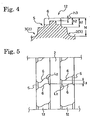
- a depth in both end regions opening to the dent parts 5 is different from a depth in a center region connecting both the end regions, as shown in Fig. 4 .
- a depth h2 of the sipe 6 in both the end regions is greater than a depth h3 of the sipe 6 in the center region (h2>h3).
- the pneumatic tire thus configured according to the present invention has the wet traction improved by the edge effect produced by the dent parts 5 thus formed.
- the land portion 12 is formed to have a two-stepped cross sectional shape at a part of each of the dent parts 5 as shown in Fig. 3 , and thus the stiffness of the land portion 12 around the dent parts 5 is ensured, which in turn improves the wear resistance of the pneumatic tire of the present invention.
- the multiple sipes 6 are each formed to traverse in the tire width direction between the dent parts 5 formed on the tread surface sides of the land portion 12, which is formed in the two-stepped shape.
- Each of the sipes 6 is formed to have a greater depth in both the end regions opening to the dent parts 5 than that of the center region, in other words, is formed to be deeper in both the end regions and to be shallower in the center region.
- the pneumatic tire thus configured is capable of maintaining excellent wet traction from an early stage to an advanced stage of wear by ensuring the stiffness of the land portion 12 around the dent parts 5 while surely producing the edge effect of the sipes 6 on the opening sides.
- the pneumatic tire of the present invention is set to have dimensions within the following ranges: the depth H of the main grooves 2, 3 is 8 mm to 15 mm; the depth h1 of the dent part 5 is 6 mm to 13 mm; the width of the sipe 6 is 0.4 mm to 1.5 mm; the depth h2 of the sipe 6 in both the end regions is 5 mm to 13 mm; and the depth h3 of the sipe 6 in the center region is 2 mm to 6 mm.
- Fig. 1 illustrates a case where five ribs extending in the tire circumferential direction are formed in the tread surface 1 as the land portions, the number and shape of the land portions are not limited to this case.
- Fig. 1 shows the land portions 11, 13, 13 while omitting various types of grooves formed in the surfaces of the land portions 11, 13, 13.
- various types of grooves suitable to achieve performance required for the tire are formed in the surface of the land portions 11, 13, 13.
- sipes 6 are formed to traverse in the tire width direction between each pair of the right and left dent parts 5, which are opposed to each other, in the land portion 12.
- an additional sipe may be provided to the land portion 12 between the dent parts 5 adjacent to each other in the tire circumferential direction. In this case, the number and the depth of such additional sipes are not limited particularly.
- the land portion 12 in the case of a tire intended to achieve excellent wet traction especially, may be formed in a block row with lug grooves 4 that are formed between the dent parts 5 adjacent in the tire circumferential direction so as to traverse the land portion 12 in the tire width direction.
- the right and left dent parts 5, 5 formed in both the side walls of the land portion 12 so as to be opposed to each other are preferably formed to be offset from each other in the tire circumferential direction as shown in Fig. 1 .
- Such placement of the dent parts 5 improves the drainage and thereby ensures the wet traction at a high level.
- the offset amount between the right and left opposed dent parts 5, 5 in the tire circumferential direction is set on a case-by-case basis depending on the width of the land portion 12, but is generally set to be on the order of 2 mm to 10 mm.
- a width W1 of a main part of the land portion 12 (a part excluding the right and left dent parts 5, 5) is set to 10 mm to 50 mm preferably, and is set to 15 mm to 30 mm more preferably.
- the width W1 of the main part of the land portion 12 is less than 10 mm, the stiffness of the land portion 12 is so decreased that the wear resistance is difficult to improve.
- the width W1 is more than 50 mm, the drainage and the snow clearing are adversely affected, so that the wet traction is difficult to ensure.
- the width W2 of the dent part 5 in the tire width direction is set to 5% to 20% preferably, and 7% to 15% more preferably, of the width W1 of the main part of the land portion 12. This setting ensures the wet traction at a high level while maintaining the excellent wear resistance.
- the shape of the sipe 6 traversing in the tire width direction between the right and left dent parts 5, 5 opposed to each other is not particularly limited, but the sipe 6 is preferably formed to have several bending parts, as shown in Figs. 1 and 2 , for the purpose of ensuring the excellent wet traction. More specifically, the sipe 6 is preferably formed so that both the end regions can extend approximately in the tire width direction while the center region can be inclined with respect to the tire width direction.
- a degree within a range of 70° to 150° preferably, and 90° to 130° more preferably, is set for an intersecting angle ⁇ between a center part of the sipe 6 in the center region inclined with respect to the tire width direction and a side part of the sipe 6 extending from the bending part of either side of the center part to the corresponding end region.
- the intersecting angle ⁇ formed by the sipe 6 bent at the bending part is set to be in the above range, the stiffness of the land portion 12 is ensured, and thereby the wear resistance is effectively prevented from decreasing.
- the dent part 5 is preferably formed to have a trapezoidal shape in a plan view. More specifically, the trapezoidal shape has, as a lower base, an edge line Q between two intersections P, P, and extends to the inner side of the land portion 12, where the intersections P, P denote intersections between the dent part 5 and the main groove 2 or 3 that defines the land portion 12 where the dent part 5 is formed.
- the trapezoidal shape is set to have the lower base L 1 within a range of 10 mm ⁇ L 1 ⁇ 20 mm in length, and an upper base L 2 within a range of 3 mm ⁇ L 2 ⁇ 15 mm in length, where L 2 ⁇ L 1 . With this configuration, the stiffness of the land portion 12 around the dent part 5 is prevented from decreasing, which, in turn, effectively improves the wet traction while ensuring the wear resistance.
- the pneumatic tire of the present invention is formed to have two or more (two in Fig. 5 ) land portions 12, where the dent parts 5 are formed, arranged side by side with a single main groove 2 in between as shown in Fig. 5 .
- the dent parts 5, 5 in the side walls, facing each other across the main groove 2, of the adjacent land portions 12 are arranged so that their upper bases can overlap each other along the tire circumferential direction and that a length L 3 of the overlapping part of the upper bases can be 3 mm to 30 mm preferably, and 5 mm to 15 mm more preferably. This arrangement allows both the wear resistance and the wet traction to be improved in good balance.
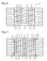
- a lug groove 4 traversing in the tire width direction is formed between each two dent parts 5, 5 in the land portion 12, which are adjacent in the tire circumferential direction.
- the lug grooves 4 thus formed divide the land portion 12 in the circumferential direction into multiple blocks, whereby the whole of the land portion 12 is formed as a block row.
- the wet traction can be improved even more surely.
- another sipe (not illustrated) traversing the land portion 12 in the tire width direction may be formed in each of the blocks.
- a lug groove 4 is formed between each two dent parts 5, 5 in the land portion 12, which are adjacent in the tire circumferential direction.
- This lug groove 4 is inclined with respect to the tire width direction and extends to the inside of a land portion 11 next to the land portion 12.
- the lug groove 4 has the tip end bent in a dogleg shape.
- sipes 7 are formed to traverse a space between the dogleg-shaped tip end of the lug groove 4 and the main groove 2 formed between the land portions 11, 12.
- dent parts 5 are formed, at certain intervals in the tire circumferential direction, in a side wall, on the main groove 3 side, of each of land portions 13.
- other sipes 7 are formed to extend in the tire width direction from each of the dent parts 5 in the land portion 13 toward a shoulder side of the tire. Employing such groove arrangement improves the wet traction to a large extent.
- the dent parts 5 are formed, at the certain intervals in the tire circumferential direction, in both the side walls of each of at least two land portions 12, 12 out of the multiple land portions that are formed in the tread surface 1 to extend in the tire circumferential direction.
- the depth h1 of each of the dent parts 5 is smaller than the depth H of the main grooves 2, 3 that define the land portion 12 where the dent part 5 is formed.
- the multiple sipes 6 traversing in the tire width direction are formed between the dent parts 5, 5 formed in both the side walls of the land portion 12.
- each of the sipes 6 is set such that the depth in both the end regions opening to the dent parts 5, 5 is great whereas the depth of the center region is smaller than that of both the end regions.
- the sipes 6 thus configured allow the wet traction and the wear resistance to be maintained at high levels in good balance from an early stage to an advanced stage of wear. Having a simple structure, the aforementioned configuration is capable of producing such an excellent effect that the configuration is usable, as a pattern structure, for a wide range of tires for all seasons.
- the tires of the present invention (Examples 1 to 3) and comparative tires (Comparative Examples 1 to 3) were fabricated in size of P265/70R17 113H with a tread pattern of the pattern shown in Fig. 7 so as to entirely have the same specifications in common except for the land portion 12.
- the tires of Examples 1 to 3 and Comparative Examples 1 to 3 were formed differently from each other in terms of the width W1 of the main part of the land portion 12, the depth h1 of the dent part 5, the depth h2 of the sipe 6 in both the end regions, and the depth h3 of the sipe 6 in the center region, as shown in Table 1.
- the main grooves 2, 3 in each of the tires were formed with a depth H of 11 mm.
- Each of tires was mounted on a rim of 17 ⁇ 8.0J, and was inflated until the air pressure reaches 210 kPa. Then, the tires were mounted as front and rear wheels on an SUV with a 6L displacement engine. The SUV was driven to run on a snowy road, and then the brakes were locked up while the SUV was running at a speed of 40 km/h. At this time, the braking distance until the SUV was stopped was measured.
- This test was conducted repeatedly five times for each type of tires in each of a brand-new condition (called “early stage of wear” in Table 1), and a worn condition with wearing of 3 mm (called “middle stage of wear” in Table 1). Thereafter, the average value of three of the five braking distances excluding the greatest and smallest values was calculated, and the wet traction was evaluated based on the inverse of the calculated average value.
- the SUV was driven to run on an asphalt road over a distance of 15,000 km at a speed of 40 km/h to 100 km/h. Then, each of the tires after the run was measured to determine step amounts around the lug grooves and around the sipes at 16 positions in the circumference surface of the tire. The average value of the step amounts thus measured was calculated, and the wear resistance was evaluated based on the inverse of the calculated average value.
- Table 1 clearly shows that the tires of the present invention achieve both wet traction and wear resistance improved in good balance, as compared with those of the tires of Comparative Examples.
Landscapes
- Engineering & Computer Science (AREA)
- Mechanical Engineering (AREA)
- Tires In General (AREA)
Claims (9)
- Luftreifen, in dem eine Mehrzahl von Bodenabschnitten, die durch Hauptrillen (2, 3) definiert sind, die sich in einer Reifenumfangsrichtung erstrecken, in einer Lauffläche ausgebildet sind, und bei dem beide Seitenwände in jedem von wenigstens zwei Bodenabschnitten (12, 12) der Mehrzahl von Bodenabschnitten mit einer Mehrzahl von Kerben (5) vorgesehen sind, die in bestimmten Abständen in der Reifenumfangsrichtung ausgebildet sind, wobei
jede der Kerben (5) eine geringere Tiefe als die Hauptrillen (2, 3), welche den Bodenabschnitt (12) definieren, wo die Kerbe (5) ausgebildet ist aufweist, wobei der Luftreifen dadurch gekennzeichnet ist, dass
eine Mehrzahl von Feinschnitten (6) jeweils ausgebildet sind, um in einer Reifenbreitenrichtung zwischen den Kerben (5), die in beiden Seitenwänden des Bodenabschnitts (12) ausgebildet sind, zu queren, und
jeder der Feinschnitte (6) in beiden Endbereichen, welche sich zu den Kerben (5) öffnen, tiefer ist als in einem mittleren Bereich zwischen beiden Endbereichen. - Luftreifen nach Anspruch 1, dadurch gekennzeichnet, dass die Kerben (5), die in beiden Seitenwänden des Bodenabschnitts (12) ausgebildet sind, vorgesehen sind, um in der Reifenumfangsrichtung voneinander versetzt zu sein.
- Luftreifen nach Anspruch 1 oder 2, dadurch gekennzeichnet, dass eine Breite W1 eines Hauptteils des Bodenabschnitts (12), in dem die Kerben (5) in beiden Seitenwänden ausgebildet sind, 10 mm bis 50 mm beträgt.
- Luftreifen nach Anspruch 3, dadurch gekennzeichnet, dass
eine Breite W2 jeder Kerbe (5) in der Reifenbreitenrichtung 5 % bis 20 % der Breite W1 des Hauptteils des Bodenabschnitts (12) beträgt. - Luftreifen nach einem der Ansprüche 1 bis 4, dadurch gekennzeichnet, dass die Feinschnitte (6) jeweils ausgebildet sind, um eine Mehrzahl von Biegungsbereichen aufzuweisen und in dem mittleren Bereich bezüglich der Reifenbreitenrichtung geneigt zu sein.
- Luftreifen nach Anspruch 5, dadurch gekennzeichnet, dass
ein Schnittwinkel zwischen einem mittleren Bereich jedes Feinschnitts (6) in dem mittleren Bereich, der bezüglich der Reifenbreitenrichtung geneigt ist, und einem Seitenbereich des Feinschnitts (6), der sich von dem Biegungsbereich an jedem Ende des mittleren Bereichs des Feinschnitts (6) zu einem entsprechenden Endbereich erstreckt, auf 70° bis 150° festgelegt ist. - Luftreifen nach einem der Ansprüche 1 bis 6, dadurch gekennzeichnet, dass
jede der Kerben (5) in einer Draufsicht sich in einer trapezförmigen Gestalt befindet, die als untere Basis eine Kantenlinie zwischen zwei Schnittpunkten der Kerbe (5) und der Hauptrille (2 oder 3), die den Bodenabschnitt (12) definiert, wo die Kerbe ausgebildet ist aufweist, und sich zu einer Innenseite des Bodenabschnitts (12) erstreckt, wobei die trapezförmige Gestalt festgelegt ist, um eine untere Basis (L1) in einem Bereich von 10 mm ≤ L1 ≤ 20 mm in der Länge und eine obere Basis (L2) in einem Bereich von 3 mm ≤ L2 ≤ 15 mm in der Länge aufzuweisen, wobei L2 < L1 ist. - Luftreifen nach Anspruch 7, dadurch gekennzeichnet, dass
zwei oder mehr Bodenabschnitte (12), wo die Kerben (5) ausgebildet sind, Seite an Seite mit einer einzelnen Hauptrille (2) dazwischen ausgebildet sind,
die Kerben (5, 5) in den Seitenwänden, die über die Hauptrille (2) einander zugewandt sind, der benachbarten Bodenabschnitte (12, 12) auf eine Weise angeordnet sind, dass die oberen Basen der Kerben (5, 5) einander entlang der Reifenumfangsrichtung überlappen, und dass eine Länge (L3) des Überlappungsbereichs der oberen Basen 3 mm bis 30 mm beträgt. - Luftreifen nach einem der Ansprüche 1 bis 8, dadurch gekennzeichnet, dass
der Bodenabschnitt (12), wo die Kerben (5) in beiden Seitenwänden ausgebildet sind, eine Nebenrille (4) aufweist, die zwischen jeweils zwei benachbarten Kerben (5) in der Reifenumfangsrichtung ausgebildet ist, und dadurch als ein Blockreihe ausgebildet ist.
Applications Claiming Priority (1)
| Application Number | Priority Date | Filing Date | Title |
|---|---|---|---|
| JP2008223486A JP4548534B2 (ja) | 2008-09-01 | 2008-09-01 | 空気入りタイヤ |
Publications (2)
| Publication Number | Publication Date |
|---|---|
| EP2159081A1 EP2159081A1 (de) | 2010-03-03 |
| EP2159081B1 true EP2159081B1 (de) | 2011-05-18 |
Family
ID=41314554
Family Applications (1)
| Application Number | Title | Priority Date | Filing Date |
|---|---|---|---|
| EP09010386A Not-in-force EP2159081B1 (de) | 2008-09-01 | 2009-08-12 | Luftreifen |
Country Status (5)
| Country | Link |
|---|---|
| US (1) | US8881779B2 (de) |
| EP (1) | EP2159081B1 (de) |
| JP (1) | JP4548534B2 (de) |
| CN (1) | CN101665065B (de) |
| AT (1) | ATE509782T1 (de) |
Families Citing this family (10)
| Publication number | Priority date | Publication date | Assignee | Title |
|---|---|---|---|---|
| JP5227355B2 (ja) * | 2010-03-19 | 2013-07-03 | 住友ゴム工業株式会社 | 重荷重用タイヤ |
| JP5698622B2 (ja) * | 2011-08-04 | 2015-04-08 | 株式会社ブリヂストン | タイヤ |
| JP5835112B2 (ja) * | 2012-06-05 | 2015-12-24 | 横浜ゴム株式会社 | 空気入りタイヤ |
| US10214054B2 (en) * | 2013-07-23 | 2019-02-26 | The Yokohama Rubber Co., Ltd. | Pneumatic tire |
| JP6138663B2 (ja) * | 2013-10-29 | 2017-05-31 | 株式会社ブリヂストン | タイヤ |
| JP6467309B2 (ja) * | 2015-07-16 | 2019-02-13 | 住友ゴム工業株式会社 | 空気入りタイヤ |
| JP6747888B2 (ja) * | 2016-06-30 | 2020-08-26 | Toyo Tire株式会社 | 空気入りタイヤ |
| USD815024S1 (en) * | 2016-09-16 | 2018-04-10 | Compagnie Generale Des Etablissements Michelin | Retread band |
| JP6904019B2 (ja) * | 2017-04-06 | 2021-07-14 | 住友ゴム工業株式会社 | タイヤ |
| JP7136658B2 (ja) * | 2018-10-22 | 2022-09-13 | Toyo Tire株式会社 | 空気入りタイヤ |
Family Cites Families (16)
| Publication number | Priority date | Publication date | Assignee | Title |
|---|---|---|---|---|
| JPH01123707U (de) * | 1988-02-12 | 1989-08-23 | ||
| JPH0253608A (ja) * | 1988-08-12 | 1990-02-22 | Sumitomo Rubber Ind Ltd | 空気入りラジアルタイヤ |
| JPH03128706A (ja) * | 1989-10-13 | 1991-05-31 | Yokohama Rubber Co Ltd:The | 空気入りラジアルタイヤ |
| JP2980970B2 (ja) * | 1990-11-30 | 1999-11-22 | 株式会社ブリヂストン | 氷結湿濡地表上での走行性能に優れる空気入りタイヤ |
| JP3159748B2 (ja) * | 1991-11-01 | 2001-04-23 | 株式会社ブリヂストン | 空気入りタイヤ |
| US6123130A (en) * | 1997-11-11 | 2000-09-26 | Bridgestone/Firestone, Inc. | Tire having improved wet stopping capability |
| US6923232B1 (en) * | 1999-06-24 | 2005-08-02 | The Goodyear Tire & Rubber Company | Tread for a light truck or automobile tire |
| EP1090781B1 (de) * | 1999-10-06 | 2005-01-12 | Sumitomo Rubber Industries Limited | Spikeloser Reifen |
| JP4392944B2 (ja) * | 2000-02-21 | 2010-01-06 | 株式会社ブリヂストン | 空気入りタイヤの陸部構造 |
| CA2430465C (en) * | 2000-11-28 | 2009-07-07 | Cooper Tire & Rubber Company | Serrated groove sides in a tire |
| JP4516342B2 (ja) * | 2004-03-31 | 2010-08-04 | 住友ゴム工業株式会社 | 重荷重用タイヤ |
| JP4268576B2 (ja) * | 2004-08-23 | 2009-05-27 | 住友ゴム工業株式会社 | 空気入りタイヤ |
| JP4886288B2 (ja) | 2005-12-08 | 2012-02-29 | 住友ゴム工業株式会社 | 空気入りタイヤ |
| JP4950491B2 (ja) * | 2005-12-29 | 2012-06-13 | 住友ゴム工業株式会社 | 重荷重用タイヤ |
| US20080271826A1 (en) * | 2007-05-03 | 2008-11-06 | Paul Bryan Maxwell | Pnuematic tire |
| JP4816675B2 (ja) * | 2008-04-22 | 2011-11-16 | 横浜ゴム株式会社 | 空気入りタイヤ |
-
2008
- 2008-09-01 JP JP2008223486A patent/JP4548534B2/ja not_active Expired - Fee Related
-
2009
- 2009-08-07 US US12/537,629 patent/US8881779B2/en not_active Expired - Fee Related
- 2009-08-12 EP EP09010386A patent/EP2159081B1/de not_active Not-in-force
- 2009-08-12 AT AT09010386T patent/ATE509782T1/de not_active IP Right Cessation
- 2009-08-18 CN CN200910163144.8A patent/CN101665065B/zh not_active Expired - Fee Related
Also Published As
| Publication number | Publication date |
|---|---|
| JP2010058540A (ja) | 2010-03-18 |
| JP4548534B2 (ja) | 2010-09-22 |
| US20100051154A1 (en) | 2010-03-04 |
| CN101665065A (zh) | 2010-03-10 |
| ATE509782T1 (de) | 2011-06-15 |
| EP2159081A1 (de) | 2010-03-03 |
| US8881779B2 (en) | 2014-11-11 |
| CN101665065B (zh) | 2012-08-29 |
Similar Documents
| Publication | Publication Date | Title |
|---|---|---|
| EP2159081B1 (de) | Luftreifen | |
| KR101562679B1 (ko) | 공기 타이어 | |
| EP2163405B1 (de) | Luftreifen | |
| CN107150555B (zh) | 充气轮胎 | |
| EP2578418B1 (de) | Luftreifen | |
| EP1669217B1 (de) | Luftreifen | |
| EP2308695B1 (de) | Luftreifen | |
| US8210222B2 (en) | Pneumatic tire | |
| US8555940B2 (en) | Pneumatic tire with tread having circumferential grooves | |
| US7311127B2 (en) | Pneumatic tire with tread having sipes | |
| CA2969727C (en) | Pneumatic tire | |
| US20070240801A1 (en) | Pneumatic Tire | |
| JP3636253B2 (ja) | 空気入りタイヤの加硫用金型 | |
| EP2186654B1 (de) | Luftreifen | |
| US9469159B2 (en) | Pneumatic tire | |
| US11046117B2 (en) | Tire | |
| CN107554200B (zh) | 充气轮胎 | |
| US8162015B2 (en) | Pneumatic tire having asymmetrical tread pattern | |
| US10814676B2 (en) | Tread for heavy truck winter tire | |
| US8281828B2 (en) | Pneumatic tire with tread having lug grooves and sipes | |
| EP1826027B1 (de) | Luftreifen | |
| US7942177B2 (en) | Pneumatic tire with tread having lug grooves, sipes, and fine groove | |
| CN104918795A (zh) | 充气轮胎 | |
| EP3995324B1 (de) | Reifen mit einer oder mehreren aussparungen in den seitlichen rillen von mindestens einem schulterteil | |
| JP4386679B2 (ja) | 冬用空気入りラジアルタイヤ |
Legal Events
| Date | Code | Title | Description |
|---|---|---|---|
| PUAI | Public reference made under article 153(3) epc to a published international application that has entered the european phase |
Free format text: ORIGINAL CODE: 0009012 |
|
| AK | Designated contracting states |
Kind code of ref document: A1 Designated state(s): AT BE BG CH CY CZ DE DK EE ES FI FR GB GR HR HU IE IS IT LI LT LU LV MC MK MT NL NO PL PT RO SE SI SK SM TR |
|
| AX | Request for extension of the european patent |
Extension state: AL BA RS |
|
| 17P | Request for examination filed |
Effective date: 20100423 |
|
| GRAP | Despatch of communication of intention to grant a patent |
Free format text: ORIGINAL CODE: EPIDOSNIGR1 |
|
| RIN1 | Information on inventor provided before grant (corrected) |
Inventor name: EBIKO, MASAHIROC/O THE YOKOHAMA RUBBER CO., LTD. |
|
| GRAS | Grant fee paid |
Free format text: ORIGINAL CODE: EPIDOSNIGR3 |
|
| GRAA | (expected) grant |
Free format text: ORIGINAL CODE: 0009210 |
|
| REG | Reference to a national code |
Ref country code: GB Ref legal event code: FG4D |
|
| REG | Reference to a national code |
Ref country code: CH Ref legal event code: EP |
|
| REG | Reference to a national code |
Ref country code: IE Ref legal event code: FG4D |
|
| REG | Reference to a national code |
Ref country code: DE Ref legal event code: R096 Ref document number: 602009001291 Country of ref document: DE Effective date: 20110630 |
|
| REG | Reference to a national code |
Ref country code: NL Ref legal event code: VDEP Effective date: 20110518 |
|
| PG25 | Lapsed in a contracting state [announced via postgrant information from national office to epo] |
Ref country code: PT Free format text: LAPSE BECAUSE OF FAILURE TO SUBMIT A TRANSLATION OF THE DESCRIPTION OR TO PAY THE FEE WITHIN THE PRESCRIBED TIME-LIMIT Effective date: 20110919 Ref country code: NO Free format text: LAPSE BECAUSE OF FAILURE TO SUBMIT A TRANSLATION OF THE DESCRIPTION OR TO PAY THE FEE WITHIN THE PRESCRIBED TIME-LIMIT Effective date: 20110818 Ref country code: LT Free format text: LAPSE BECAUSE OF FAILURE TO SUBMIT A TRANSLATION OF THE DESCRIPTION OR TO PAY THE FEE WITHIN THE PRESCRIBED TIME-LIMIT Effective date: 20110518 Ref country code: SE Free format text: LAPSE BECAUSE OF FAILURE TO SUBMIT A TRANSLATION OF THE DESCRIPTION OR TO PAY THE FEE WITHIN THE PRESCRIBED TIME-LIMIT Effective date: 20110518 Ref country code: HR Free format text: LAPSE BECAUSE OF FAILURE TO SUBMIT A TRANSLATION OF THE DESCRIPTION OR TO PAY THE FEE WITHIN THE PRESCRIBED TIME-LIMIT Effective date: 20110518 |
|
| PG25 | Lapsed in a contracting state [announced via postgrant information from national office to epo] |
Ref country code: GR Free format text: LAPSE BECAUSE OF FAILURE TO SUBMIT A TRANSLATION OF THE DESCRIPTION OR TO PAY THE FEE WITHIN THE PRESCRIBED TIME-LIMIT Effective date: 20110819 Ref country code: LV Free format text: LAPSE BECAUSE OF FAILURE TO SUBMIT A TRANSLATION OF THE DESCRIPTION OR TO PAY THE FEE WITHIN THE PRESCRIBED TIME-LIMIT Effective date: 20110518 Ref country code: ES Free format text: LAPSE BECAUSE OF FAILURE TO SUBMIT A TRANSLATION OF THE DESCRIPTION OR TO PAY THE FEE WITHIN THE PRESCRIBED TIME-LIMIT Effective date: 20110829 Ref country code: IS Free format text: LAPSE BECAUSE OF FAILURE TO SUBMIT A TRANSLATION OF THE DESCRIPTION OR TO PAY THE FEE WITHIN THE PRESCRIBED TIME-LIMIT Effective date: 20110918 Ref country code: FI Free format text: LAPSE BECAUSE OF FAILURE TO SUBMIT A TRANSLATION OF THE DESCRIPTION OR TO PAY THE FEE WITHIN THE PRESCRIBED TIME-LIMIT Effective date: 20110518 Ref country code: BE Free format text: LAPSE BECAUSE OF FAILURE TO SUBMIT A TRANSLATION OF THE DESCRIPTION OR TO PAY THE FEE WITHIN THE PRESCRIBED TIME-LIMIT Effective date: 20110518 Ref country code: SI Free format text: LAPSE BECAUSE OF FAILURE TO SUBMIT A TRANSLATION OF THE DESCRIPTION OR TO PAY THE FEE WITHIN THE PRESCRIBED TIME-LIMIT Effective date: 20110518 Ref country code: CY Free format text: LAPSE BECAUSE OF FAILURE TO SUBMIT A TRANSLATION OF THE DESCRIPTION OR TO PAY THE FEE WITHIN THE PRESCRIBED TIME-LIMIT Effective date: 20110518 Ref country code: AT Free format text: LAPSE BECAUSE OF FAILURE TO SUBMIT A TRANSLATION OF THE DESCRIPTION OR TO PAY THE FEE WITHIN THE PRESCRIBED TIME-LIMIT Effective date: 20110518 |
|
| PG25 | Lapsed in a contracting state [announced via postgrant information from national office to epo] |
Ref country code: NL Free format text: LAPSE BECAUSE OF FAILURE TO SUBMIT A TRANSLATION OF THE DESCRIPTION OR TO PAY THE FEE WITHIN THE PRESCRIBED TIME-LIMIT Effective date: 20110518 Ref country code: MT Free format text: LAPSE BECAUSE OF FAILURE TO SUBMIT A TRANSLATION OF THE DESCRIPTION OR TO PAY THE FEE WITHIN THE PRESCRIBED TIME-LIMIT Effective date: 20110518 |
|
| PG25 | Lapsed in a contracting state [announced via postgrant information from national office to epo] |
Ref country code: EE Free format text: LAPSE BECAUSE OF FAILURE TO SUBMIT A TRANSLATION OF THE DESCRIPTION OR TO PAY THE FEE WITHIN THE PRESCRIBED TIME-LIMIT Effective date: 20110518 Ref country code: CZ Free format text: LAPSE BECAUSE OF FAILURE TO SUBMIT A TRANSLATION OF THE DESCRIPTION OR TO PAY THE FEE WITHIN THE PRESCRIBED TIME-LIMIT Effective date: 20110518 |
|
| PG25 | Lapsed in a contracting state [announced via postgrant information from national office to epo] |
Ref country code: DK Free format text: LAPSE BECAUSE OF FAILURE TO SUBMIT A TRANSLATION OF THE DESCRIPTION OR TO PAY THE FEE WITHIN THE PRESCRIBED TIME-LIMIT Effective date: 20110518 Ref country code: RO Free format text: LAPSE BECAUSE OF FAILURE TO SUBMIT A TRANSLATION OF THE DESCRIPTION OR TO PAY THE FEE WITHIN THE PRESCRIBED TIME-LIMIT Effective date: 20110518 Ref country code: PL Free format text: LAPSE BECAUSE OF FAILURE TO SUBMIT A TRANSLATION OF THE DESCRIPTION OR TO PAY THE FEE WITHIN THE PRESCRIBED TIME-LIMIT Effective date: 20110518 Ref country code: SK Free format text: LAPSE BECAUSE OF FAILURE TO SUBMIT A TRANSLATION OF THE DESCRIPTION OR TO PAY THE FEE WITHIN THE PRESCRIBED TIME-LIMIT Effective date: 20110518 |
|
| PLBE | No opposition filed within time limit |
Free format text: ORIGINAL CODE: 0009261 |
|
| STAA | Information on the status of an ep patent application or granted ep patent |
Free format text: STATUS: NO OPPOSITION FILED WITHIN TIME LIMIT |
|
| PG25 | Lapsed in a contracting state [announced via postgrant information from national office to epo] |
Ref country code: MC Free format text: LAPSE BECAUSE OF NON-PAYMENT OF DUE FEES Effective date: 20110831 |
|
| 26N | No opposition filed |
Effective date: 20120221 |
|
| REG | Reference to a national code |
Ref country code: FR Ref legal event code: ST Effective date: 20120430 |
|
| REG | Reference to a national code |
Ref country code: IE Ref legal event code: MM4A |
|
| PG25 | Lapsed in a contracting state [announced via postgrant information from national office to epo] |
Ref country code: IT Free format text: LAPSE BECAUSE OF FAILURE TO SUBMIT A TRANSLATION OF THE DESCRIPTION OR TO PAY THE FEE WITHIN THE PRESCRIBED TIME-LIMIT Effective date: 20110518 |
|
| REG | Reference to a national code |
Ref country code: DE Ref legal event code: R097 Ref document number: 602009001291 Country of ref document: DE Effective date: 20120221 |
|
| PG25 | Lapsed in a contracting state [announced via postgrant information from national office to epo] |
Ref country code: IE Free format text: LAPSE BECAUSE OF NON-PAYMENT OF DUE FEES Effective date: 20110812 |
|
| PG25 | Lapsed in a contracting state [announced via postgrant information from national office to epo] |
Ref country code: FR Free format text: LAPSE BECAUSE OF NON-PAYMENT OF DUE FEES Effective date: 20110831 |
|
| PG25 | Lapsed in a contracting state [announced via postgrant information from national office to epo] |
Ref country code: MK Free format text: LAPSE BECAUSE OF FAILURE TO SUBMIT A TRANSLATION OF THE DESCRIPTION OR TO PAY THE FEE WITHIN THE PRESCRIBED TIME-LIMIT Effective date: 20110518 |
|
| PG25 | Lapsed in a contracting state [announced via postgrant information from national office to epo] |
Ref country code: SM Free format text: LAPSE BECAUSE OF FAILURE TO SUBMIT A TRANSLATION OF THE DESCRIPTION OR TO PAY THE FEE WITHIN THE PRESCRIBED TIME-LIMIT Effective date: 20110518 |
|
| PG25 | Lapsed in a contracting state [announced via postgrant information from national office to epo] |
Ref country code: LU Free format text: LAPSE BECAUSE OF NON-PAYMENT OF DUE FEES Effective date: 20110812 |
|
| PG25 | Lapsed in a contracting state [announced via postgrant information from national office to epo] |
Ref country code: BG Free format text: LAPSE BECAUSE OF FAILURE TO SUBMIT A TRANSLATION OF THE DESCRIPTION OR TO PAY THE FEE WITHIN THE PRESCRIBED TIME-LIMIT Effective date: 20110818 |
|
| PG25 | Lapsed in a contracting state [announced via postgrant information from national office to epo] |
Ref country code: TR Free format text: LAPSE BECAUSE OF FAILURE TO SUBMIT A TRANSLATION OF THE DESCRIPTION OR TO PAY THE FEE WITHIN THE PRESCRIBED TIME-LIMIT Effective date: 20110518 |
|
| PG25 | Lapsed in a contracting state [announced via postgrant information from national office to epo] |
Ref country code: HU Free format text: LAPSE BECAUSE OF FAILURE TO SUBMIT A TRANSLATION OF THE DESCRIPTION OR TO PAY THE FEE WITHIN THE PRESCRIBED TIME-LIMIT Effective date: 20110518 |
|
| REG | Reference to a national code |
Ref country code: CH Ref legal event code: PL |
|
| GBPC | Gb: european patent ceased through non-payment of renewal fee |
Effective date: 20130812 |
|
| PG25 | Lapsed in a contracting state [announced via postgrant information from national office to epo] |
Ref country code: CH Free format text: LAPSE BECAUSE OF NON-PAYMENT OF DUE FEES Effective date: 20130831 Ref country code: LI Free format text: LAPSE BECAUSE OF NON-PAYMENT OF DUE FEES Effective date: 20130831 |
|
| PG25 | Lapsed in a contracting state [announced via postgrant information from national office to epo] |
Ref country code: GB Free format text: LAPSE BECAUSE OF NON-PAYMENT OF DUE FEES Effective date: 20130812 |
|
| PGFP | Annual fee paid to national office [announced via postgrant information from national office to epo] |
Ref country code: DE Payment date: 20140806 Year of fee payment: 6 |
|
| REG | Reference to a national code |
Ref country code: DE Ref legal event code: R119 Ref document number: 602009001291 Country of ref document: DE |
|
| PG25 | Lapsed in a contracting state [announced via postgrant information from national office to epo] |
Ref country code: DE Free format text: LAPSE BECAUSE OF NON-PAYMENT OF DUE FEES Effective date: 20160301 |