EP2157594A1 - Vakuumhülle mit selbstausrichtender Endabschirmung, Vakuumschalter, Vakuumschutzschalter und Verfahren damit - Google Patents
Vakuumhülle mit selbstausrichtender Endabschirmung, Vakuumschalter, Vakuumschutzschalter und Verfahren damit Download PDFInfo
- Publication number
- EP2157594A1 EP2157594A1 EP09010351A EP09010351A EP2157594A1 EP 2157594 A1 EP2157594 A1 EP 2157594A1 EP 09010351 A EP09010351 A EP 09010351A EP 09010351 A EP09010351 A EP 09010351A EP 2157594 A1 EP2157594 A1 EP 2157594A1
- Authority
- EP
- European Patent Office
- Prior art keywords
- shield
- open end
- ceramic tube
- open
- generally
- Prior art date
- Legal status (The legal status is an assumption and is not a legal conclusion. Google has not performed a legal analysis and makes no representation as to the accuracy of the status listed.)
- Granted
Links
- 238000000034 method Methods 0.000 title claims description 13
- 239000000919 ceramic Substances 0.000 claims abstract description 114
- 230000007246 mechanism Effects 0.000 claims description 9
- 238000005219 brazing Methods 0.000 claims 1
- 239000002184 metal Substances 0.000 description 6
- 229910052751 metal Inorganic materials 0.000 description 6
- 230000006872 improvement Effects 0.000 description 3
- 238000000429 assembly Methods 0.000 description 2
- 230000008030 elimination Effects 0.000 description 2
- 238000003379 elimination reaction Methods 0.000 description 2
- 238000004519 manufacturing process Methods 0.000 description 2
- 239000000615 nonconductor Substances 0.000 description 2
- 230000004044 response Effects 0.000 description 2
- RYGMFSIKBFXOCR-UHFFFAOYSA-N Copper Chemical compound [Cu] RYGMFSIKBFXOCR-UHFFFAOYSA-N 0.000 description 1
- 230000002159 abnormal effect Effects 0.000 description 1
- 230000000712 assembly Effects 0.000 description 1
- 239000004020 conductor Substances 0.000 description 1
- 229910052802 copper Inorganic materials 0.000 description 1
- 239000010949 copper Substances 0.000 description 1
- 230000008878 coupling Effects 0.000 description 1
- 238000010168 coupling process Methods 0.000 description 1
- 238000005859 coupling reaction Methods 0.000 description 1
- 238000010292 electrical insulation Methods 0.000 description 1
- 239000012212 insulator Substances 0.000 description 1
- 238000002955 isolation Methods 0.000 description 1
- 230000004048 modification Effects 0.000 description 1
- 238000012986 modification Methods 0.000 description 1
- 230000009467 reduction Effects 0.000 description 1
Images


Classifications
-
- H—ELECTRICITY
- H01—ELECTRIC ELEMENTS
- H01H—ELECTRIC SWITCHES; RELAYS; SELECTORS; EMERGENCY PROTECTIVE DEVICES
- H01H33/00—High-tension or heavy-current switches with arc-extinguishing or arc-preventing means
- H01H33/60—Switches wherein the means for extinguishing or preventing the arc do not include separate means for obtaining or increasing flow of arc-extinguishing fluid
- H01H33/66—Vacuum switches
- H01H33/662—Housings or protective screens
- H01H33/66261—Specific screen details, e.g. mounting, materials, multiple screens or specific electrical field considerations
- H01H2033/66276—Details relating to the mounting of screens in vacuum switches
Definitions
- This invention pertains generally to vacuum interrupters which provide protection in electric power circuits and, more particularly, to vacuum interrupters or vacuum envelopes including end shields that provide a self-alignment function.
- the invention also pertains to a self-alignment method for ends shields of vacuum interrupters.
- the invention further pertains to vacuum circuit interrupters including vacuum interrupters having end shields that provide a self-alignment function.
- Vacuum circuit interrupters provide protection for electrical systems from electrical fault conditions such as current overloads, short circuits, and low level voltage conditions.
- vacuum circuit interrupters include a spring-powered or other suitable operating mechanism, which opens electrical contacts inside a number of vacuum interrupters to interrupt the current flowing through the conductors in an electrical system in response to abnormal conditions.
- Vacuum interrupters include separable main contacts disposed within an insulated and hermetically sealed vacuum chamber.
- the vacuum chamber typically includes a number of sections of ceramics (e.g., a number of tubular ceramic portions) for electrical insulation capped by a number of end members (e.g., metal components, such as metal end plates; end caps; seal cups) to form an envelope in which a vacuum may be drawn.
- the ceramic section is typically cylindrical; however, other suitable cross-sectional shapes may be used. Two end members are typically employed. Where there are multiple ceramic sections, an internal center shield is disposed between the ceramic sections.
- the main contacts are electrically connected to the external circuit to be protected by the vacuum circuit interrupter by electrode stems, typically an elongated member made from high purity copper.
- electrode stems typically an elongated member made from high purity copper.
- a contact and a stem are identified collectively as an electrode.
- one of the contacts is fixed relative to the vacuum chamber as well as to the external circuit.
- the fixed contact is mounted in the vacuum envelope on a first electrode extending through one end member.
- the other contact is movable relative to the vacuum envelope.
- the moveable contact is mounted on a moveable electrode axially slideable through the other end member.
- the movable contact is driven by the operating mechanism and the motion of the operating mechanism is transferred inside the vacuum envelope by a coupling that includes a sealed metallic bellows.
- the fixed and moveable contacts form a pair of separable contacts which are opened and closed by movement of the moveable electrode in response to the operating mechanism located outside of the vacuum envelope.
- the electrodes, end members, bellows, ceramic shell(s), and the internal center shield, if any, are joined together to form a vacuum interrupter capable of maintaining a vacuum at a suitable level for an extended period of time.
- the separable contacts When the separable contacts are opened with current flowing through the vacuum interrupter, a metal-vapor arc is struck between the contact surfaces. This arc continues until the current is interrupted, typically as the alternating current goes through a zero crossing.
- several metal vapor shields are typically provided within the vacuum envelope.
- the metal vapor shields can be between the contacts and the ceramic inside the vacuum envelope, and at one or both ends of the envelope.
- a vacuum envelope including an end shield comprising a first end having an opening therein, a second open end, an intermediate portion disposed between the first end and the second open end, and a flange portion disposed from the second open end.
- the flange portion extends outwardly from the intermediate portion and generally back toward the first end.
- the flange portion includes an edge engaging an inside surface of an end member and is normally offset from an insulative tube of the vacuum envelope.
- a vacuum interrupter comprises: a ceramic tube including a first open end and a second open end; a first end member secured to the first open end of the ceramic tube; a second end member including an inside surface, the second end member secured to the second open end of the ceramic tube, the first and second end members cooperating with the ceramic tube to form a vacuum envelope; an end shield comprising: a first end having an opening therein, a second open end, an intermediate portion disposed between the first end and the second open end of the end shield, and a flange portion disposed from the second open end of the end shield, the flange portion extending outwardly from the intermediate portion and generally back toward the first end, the flange portion including an edge engaging the inside surface of the second end member, the flange portion being normally offset from the ceramic tube; a fixed contact mounted on a fixed electrode extending through the second end member and extending through the opening of the first end of the end shield; and a moveable contact mounted on a moveable electrode extending through
- the intermediate portion and the flange portion of the end shield may form a generally V-shaped structure at the second open end of the end shield;
- the generally V-shaped structure may include a free circular edge forming the edge of the flange portion and an end;
- the inside surface of the second end member may include a cylindrical surface and an end surface normal to the cylindrical surface;
- the free circular edge of the generally V-shaped structure may engage the cylindrical surface;
- the end of the generally V-shaped structure may engage the end surface; and the generally V-shaped structure may be structured to self-align the end shield within the second end member.
- a braze ring may be disposed at the end surface of the second end member and proximate the end of the generally V-shaped structure; and the end of the generally V-shaped structure may be brazed to the end surface of the second end member.
- the end of the generally V-shaped structure may not be secured to the end surface of the second end member; and the end shield may be captured between the end surface of the second end member and the second open end of the ceramic tube.
- the second end member may further include a first end having an opening therein, a second open end, and a cylindrical portion disposed between the first end of the second end member and the second open end of the second end member; the cylindrical portion may form the inside surface; the fixed electrode may extend through the opening of the first end of the second end member; and the second open end of the second end member may be secured to the second open end of the ceramic tube.
- a braze washer may be disposed between the second open end of the second end member and the second open end of the ceramic tube; and the second open end of the second end member may be brazed to the second open end of the ceramic tube.
- Only the intermediate portion of the end shield may engage the ceramic tube.
- the intermediate portion of the end shield may be a generally cylindrical portion including a plurality of dimples which engage the ceramic tube. Only the dimples of the end shield may engage the ceramic tube.
- the second end member may further include a first end, a second open end secured to the second open end of the ceramic tube, and a cylindrical portion disposed between the first end of the second end member and the second open end of the second end member; the cylindrical portion may have a first height; and the flange portion of the end shield may have a second height, which is smaller than the first height, in order that the edge of the flange portion is normally offset from where the second open end of the second end member is secured to the second open end of the ceramic tube.
- a vacuum envelope is for a fixed contact mounted on a fixed electrode and a moveable contact mounted on a moveable electrode.
- the vacuum envelope comprises: an insulative tube including a first open end and a second open end; a first end member secured to the first open end of the insulative tube; a second end member including an inside surface, the second end member secured to the second open end of the insulative tube; and an end shield comprising: a first end having an opening therein, a second open end, an intermediate portion disposed between the first end and the second open end of the end shield, and a flange portion disposed from the second open end of the end shield, the flange portion extending outwardly from the intermediate portion and generally back toward the first end, the flange portion including an edge engaging the inside surface of the second end member, the flange portion being normally offset from the insulative tube.
- a method of self-aligning an end shield of a vacuum interrupter comprises: employing a ceramic tube including a first open end and a second open end; securing a first end member to the first open end of the ceramic tube; securing a second end member to the second open end of the ceramic tube; forming a vacuum envelope with the first and second end members; employing an end shield comprising a first end having an opening therein, a second open end, and an intermediate portion disposed between the first end and the second open end of the end shield; disposing a flange portion including an edge from the second open end of the end shield; extending the flange portion outwardly from the intermediate portion and generally back toward the first end; engaging the edge with the inside surface of the second end member; and offsetting the flange portion from the ceramic tube.
- a vacuum circuit interrupter comprises: a vacuum interrupter comprising: a ceramic tube including a first open end and a second open end, a first end member secured to the first open end of the ceramic tube, a second end member including an inside surface, the second end member secured to the second open end of the ceramic tube, the first and second end members cooperating with the ceramic tube to form a vacuum envelope, an end shield comprising: a first end having an opening therein, a second open end, an intermediate portion disposed between the first end and the second open end of the end shield, and a flange portion disposed from the second open end of the end shield, the flange portion extending outwardly from the intermediate portion and generally back toward the first end, the flange portion including an edge engaging the inside surface of the second end member, the flange portion being normally offset from the ceramic tube, a fixed contact mounted on a fixed electrode extending through the second end member and extending through the opening of the first end of the end shield, and a moveable contact mounted on a
- the intermediate portion of the end shield may be a generally cylindrical portion including a plurality of dimples which engage the ceramic tube; and only the dimples of the end shield may engage the ceramic tube.
- number shall mean one or an integer greater than one (i.e., a plurality).
- the vacuum interrupter 1 includes an insulative tube, such as the example ceramic tube 3, which with end members 5 and 7 forms a vacuum envelope 9.
- a fixed contact 11 is mounted on a fixed electrode 13, which extends through the end member 5.
- a moveable contact 15 is carried by a moveable electrode 17 and extends through the end member 7.
- a bellows 19 forms a seal between the end member 7 and the moveable electrode 17 while allowing axial movement of the moveable electrode 17 to bring the moveable contact 15 into and out of contact with the fixed contact 11.
- the fixed contact 11 and moveable contact 15 form separable contacts 21, which when closed, complete an electrical circuit between the fixed electrode 13 and the moveable electrode 17, and when opened by axial movement of the moveable electrode 17 interrupt current flowing through the vacuum interrupter 1.
- the moveable electrode 17 is moved axially to open and close the separable contacts 21 by an operating mechanism 22 ( Figure 2 ) connected to the moveable electrode 17 outside of the vacuum envelope 9.
- the vapor shield 25 is a floating shield. That is, it is not electrically connected to either electrode 13,17 so that its potential floats. To provide this electrical isolation, the vapor shield 25 is supported by the ceramic tube 3 which, as mentioned, is an electrical insulator.
- the ceramic tube 3 has a groove 29 in the center thereof. A snap ring 31 is popped into that groove 29. The shield 25 is then lowered into the ceramic tube 3 and brazed onto the snap ring 31.
- the invention is applicable to vacuum interrupters including a plurality of ceramic tubes (e.g., without limitation, an upper ceramic and a lower ceramic, with a center shield flange sandwiched therebetween).
- a plurality of ceramic tubes e.g., without limitation, an upper ceramic and a lower ceramic, with a center shield flange sandwiched therebetween.
- the example ceramic tube 3 includes a first open end 33 and a second open end 35.
- the end member 7 is suitably secured (e.g., brazed) to the first open end 33 of the ceramic tube 3.
- the other end member 5 e.g., without limitation, a seal cup
- the end members 5,7 cooperate with the ceramic tube 3 to form the vacuum envelope 9.
- an end shield 39 includes a first end 41 having an opening 43 therein, a second open end 45, an intermediate portion 47 disposed between the first end 41 and the second open end 45, and a flange portion 49 disposed from the second open end 45.
- the flange portion 49 extends outwardly from the intermediate portion 47 and generally back toward the first end 41.
- the flange portion 49 extends outwardly from the intermediate portion 47 at an angle of about 10 degrees, although the flange portion 49 may be generally parallel to the intermediate portion 47 or may be disposed any suitable angle of less than 90 degrees, as long as the edge 51 of the flange portion 49 engages the inside surface 37 of the second end member 5.
- the example flange portion 49 includes the edge 51 engaging the inside surface 37 of the second end member 5.
- the flange portion 49 is normally offset from the ceramic tube 3.
- the fixed contact 11 is mounted on the fixed electrode 13 and extends through the second end member 5 and through the opening 43 of the first end 41 of the end shield 39.
- the moveable contact 15 is mounted on the moveable electrode 17 and extends through the first end member 7 and axially reciprocates into and out of contact with the fixed contact 11.
- the vacuum envelope 9 is for the fixed contact 11 and the moveable contact 15.
- the vacuum envelope 9 includes, for example, the ceramic tube 3, the end members 5,7, and the end shield 39.
- a method of self-aligning the end shield 39 includes employing the ceramic tube 3 including the first open end 33 and the second open end 35; securing the first end member 7 to the first open end 33 of the ceramic tube 3; securing the second end member 5 to the second open end 35 of the ceramic tube 3; forming the vacuum envelope 9 with the first and second end members 5,7; employing the end shield 39 including the first end 41 having the opening 43 therein, the second open end 45, and the intermediate portion 47 disposed between the first end 41 and the second open end 45; disposing the flange portion 49 including the edge 51 from the second open end 45; extending the flange portion 49 outwardly from the intermediate portion 47 and generally back toward the first end 41; engaging the edge 51 with the inside surface 37 of the second end member 5; and offsetting the flange portion 49 from the ceramic tube 3.
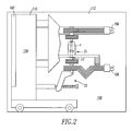
- a vacuum circuit interrupter such as the example vacuum circuit breaker 100, incorporates the vacuum interrupter 1 of Figure 1 .
- the circuit breaker 100 preferably includes a front panel 102, which has controls for manually operating the circuit breaker 100 and changing the state of the separable contacts 21 to either an open or closed condition, and a circuit breaker housing 104.
- the circuit breaker 100 has upper and lower (with respect to Figure 2 ) terminals 106,108, and may have additional terminals not visible in Figure 2 , which can be connected to a line (not shown) and a load (not shown).
- the circuit breaker 100 has a low voltage portion 110 coupled to the front panel 102 and a high voltage portion 112 including the vacuum interrupter 1.
- the vacuum circuit breaker 100 also includes the operating mechanism 22 structured to axially reciprocate the moveable electrode 17 and move the moveable contact 15 ( Figure 1 ) into and out of contact with the fixed contact 11 ( Figure 1 ). Although one pole and one vacuum interrupter 1 are shown, it will be appreciated that the invention is applicable to vacuum circuit interrupters having any number of poles.
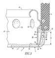
- an end portion of the vacuum interrupter 1 of Figure 1 is shown including the ceramic tube 3, the end shield 39 and the end member 5.
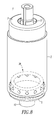
- the intermediate portion 47 of the end shield 39 is a generally cylindrical portion 47 including a plurality of dimples 53 (as best shown in Figures 4 and 5 ) which engage the ceramic tube 3. Only the dimples 53 of the end shield 39 engage the ceramic tube 3.
- the intermediate portion 47 and the flange portion 49 of the end shield 39 form a generally V-shaped structure 55 at the second open end 45 of the end shield 39.
- the generally V-shaped structure 55 includes a free circular edge 57 forming the edge 51 of the flange portion 49 and an end 59, which forms the second open end 45 of the end shield 39.
- the inside surface 37 of the second end member 5 includes a cylindrical surface 61 and an end surface 63 normal to the cylindrical surface 61.
- the free circular edge 57 of the generally V-shaped structure 55 engages the cylindrical surface 61.
- the end 59 of the generally V-shaped structure 55 engages the end surface 63.
- the generally V-shaped structure 55 is structured to self-align the end shield 39 within the second end member 5, while the dimples 53 perform a corresponding self-alignment function of the end shield 39 within the ceramic tube 3.
- a braze ring 65 is disposed at the end surface 63 of the second end member 5 and proximate the end 59 of the generally V-shaped structure 55.
- the end 59 of the generally V-shaped structure 55 is brazed to the end surface 63 of the second end member 5. If the end 59 of the generally V-shaped structure 55 is erroneously not secured to (or if it becomes unsecured from) the end surface 63 of the second end member 5, then the end shield 39 is advantageously captured between the end surface 63 of the second end member 5 and the second open end 35 of the ceramic tube 3.
- a braze washer 67 is disposed between the second open end 69 of the second end member 5 and the second open end 35 of the ceramic tube 3.
- the second open end 69 of the second end member 5 is brazed to the second open end 35 of the ceramic tube 3.
- the intermediate portion 47 of the end shield 39 is a generally cylindrical portion 47 including the dimples 53 which engage the ceramic tube 3.
- the second end member 5 further includes a first end 71, the second open end 69 secured to the second open end 35 of the ceramic tube 3, and a cylindrical portion 73 disposed between the first end 71 and the second open end 69.
- the cylindrical portion 73 has a first height 75.
- the flange portion 49 of the end shield 39 has a second height 77 ( Figure 3 ), which is smaller than the first height 75, in order that the circular edge 51 of the flange portion 49 and the flange portion 49 are normally offset from where the second open end 69 of the second end member 5 is secured to the second open end 35 of the ceramic tube 3.
- the end shield 39 includes a curved flange 78 that engages the inside surface 37 of the end member 5.
- the curved flange 78 provides a self-alignment function, which advantageously acts to align the end shield 39 within the end member 5.
- the end shield 39 also includes the dimples 53, which provide an additional alignment function. The end shield 39 only engages the ceramic tube 3 at the dimples 53.
- a relatively narrow edge 69 of the end member 5 engages the bottom (with respect to Figure 3 ) end 35 of the ceramic tube 3.
- the end member second open end 69 is brazed (e.g., without limitation, using the braze washer 67) to the ceramic tube second open end 35.
- the vacuum interrupter 1 is assembled into the vacuum circuit breaker 100 with the moveable electrode 17 (best shown in Figure 1 ) facing down (with respect to Figure 2 ).
- Figure 3 shows the end member 5 and the end shield 39 for the fixed electrode 13 facing down (with respect to Figure 3 ).
- the end shield 39 does not contact the bottom (with respect to Figure 3 ) end 35 of the ceramic tube 3.
- the end shield 39 on the fixed electrode end was erroneously loose (e.g., caused by a forgotten braze at the braze ring 65), then, in the position shown in Figure 2 , it would "fall".
- the flange portion 49 of the end shield 39 is structured to be slightly lower in height than the corresponding height of the end member 5, in order that it does not interfere with the end member/ceramic tube braze joint.
- the second end member 5 further includes a first end 71 having an opening 79 therein, the second open end 69, and the cylindrical portion 73 ( Figure 6 ) disposed between the first end 71 and the second open end 69.
- the cylindrical portion 73 forms the inside surface 61.
- the fixed electrode 13 extends through the opening 79 of the first end 71 of the second end member 5.
- the second open end 69 of the second end member 5 is secured to the second open end 35 of the ceramic tube 3.
- the advantages of the disclosed vacuum interrupter 1 and end shield 39 include: (1) improved self-alignment as is provided by the flange portion 49 of the end shield 39; (2) a cost savings and an inventory reduction since the self-alignment flange portion 49 centers the end shield 39 within the end member 5, which eliminates an external self-aligning ceramic fixture (not shown), an internal braze ring (not shown) and an internal alignment flange (not shown); (3) elimination of an external self-aligning ceramic fixture and corresponding fixture weight speed up furnace run times and productivity; (4) elimination of an external self-aligning ceramic fixture, which can shield radiant heat from braze joints and result in a relatively poor joint and leaking vacuum interrupters, enable heat to directly penetrate the braze joints, thereby reducing leak-related scrap; (5) error-proofing, since if the end shield-to-end member braze is forgotten, the end shield flange 49 is trapped by the end 35 of the ceramic tube 3, as was discussed above; (6) reduced misalignment through improved self-alignment; and (7) improved productivity
- end shield 39 can be employed with one or both of the end members (e.g., end members 5,7) of a vacuum interrupter.
Landscapes
- High-Tension Arc-Extinguishing Switches Without Spraying Means (AREA)
Applications Claiming Priority (1)
| Application Number | Priority Date | Filing Date | Title |
|---|---|---|---|
| US12/189,320 US8039771B2 (en) | 2008-08-11 | 2008-08-11 | Vacuum envelope including self-aligning end shield, vacuum interrupter, vacuum circuit interrupter and method including the same |
Publications (2)
| Publication Number | Publication Date |
|---|---|
| EP2157594A1 true EP2157594A1 (de) | 2010-02-24 |
| EP2157594B1 EP2157594B1 (de) | 2014-06-04 |
Family
ID=41268164
Family Applications (1)
| Application Number | Title | Priority Date | Filing Date |
|---|---|---|---|
| EP09010351.6A Active EP2157594B1 (de) | 2008-08-11 | 2009-08-11 | Vakuumhülle mit selbstausrichtender Endabschirmung, Vakuumschalter, Vakuumschutzschalter und Verfahren damit |
Country Status (2)
| Country | Link |
|---|---|
| US (1) | US8039771B2 (de) |
| EP (1) | EP2157594B1 (de) |
Cited By (2)
| Publication number | Priority date | Publication date | Assignee | Title |
|---|---|---|---|---|
| EP2960921A1 (de) * | 2014-06-27 | 2015-12-30 | Schneider Electric Industries SAS | Selbstzentrierende einheit für vakuumröhre, und entsprechende vakuumröhre |
| CN108352272A (zh) * | 2015-11-20 | 2018-07-31 | 伊顿智能动力有限公司 | 通过将接触间隙远离中心凸缘轴向位置移动来最大化cu-cr浮动中心罩组件的壁厚 |
Families Citing this family (16)
| Publication number | Priority date | Publication date | Assignee | Title |
|---|---|---|---|---|
| US8269130B2 (en) * | 2010-02-24 | 2012-09-18 | Eaton Corporation | Retainer, vacuum interrupter, and electrical switching apparatus including the same |
| KR101520552B1 (ko) * | 2010-07-07 | 2015-05-14 | 지멘스 엘티디 | 전기 절연기 |
| DE102011006013B3 (de) * | 2011-03-24 | 2012-08-16 | Siemens Aktiengesellschaft | Vakuumschaltröhre und Schalterpol |
| KR200464610Y1 (ko) * | 2011-09-14 | 2013-01-11 | 엘에스산전 주식회사 | 진공 인터럽터 |
| RU2532627C2 (ru) * | 2012-08-14 | 2014-11-10 | Общество с ограниченной ответственностью "Вакуумные технологии" | Способ изготовления вакуумных дугогасительных камер (вдк) |
| US10978256B1 (en) | 2013-03-15 | 2021-04-13 | Innovative Switchgear IP, LLC | Electrical switching device |
| CN104362035B (zh) * | 2014-10-31 | 2017-10-10 | 平高集团有限公司 | 一种高压开关装置及其灭弧室、罐体 |
| CN104362031B (zh) * | 2014-10-31 | 2017-09-29 | 平高集团有限公司 | 罐体及使用该罐体的灭弧室、高压开关装置 |
| CN104362535B (zh) * | 2014-10-31 | 2017-05-03 | 平高集团有限公司 | 一种罐体及使用该罐体的灭弧室、封闭式开关装置 |
| US9704658B2 (en) | 2014-11-17 | 2017-07-11 | Eaton Corporation | Vacuum switching apparatus, and contact assembly and method of securing an electrical contact to an electrode therefor |
| KR101697580B1 (ko) * | 2015-02-23 | 2017-02-01 | 엘에스산전 주식회사 | 진공 인터럽터 |
| US9842713B2 (en) * | 2016-03-30 | 2017-12-12 | Eaton Corporation | Vacuum circuit interrupter |
| JP6342090B2 (ja) * | 2016-04-19 | 2018-06-13 | 三菱電機株式会社 | 真空バルブ |
| DE102017222415B4 (de) * | 2017-12-11 | 2021-03-25 | Siemens Aktiengesellschaft | Schirmelement für eine Vakuumschaltröhre |
| USD937331S1 (en) * | 2018-12-19 | 2021-11-30 | Aktiebolaget Skf | Housing for ball bearings |
| FR3118278A1 (fr) * | 2020-12-23 | 2022-06-24 | Schneider Electric Industries Sas | Contact de coupure électrique |
Citations (3)
| Publication number | Priority date | Publication date | Assignee | Title |
|---|---|---|---|---|
| EP0419940A2 (de) * | 1989-09-23 | 1991-04-03 | ABB Calor Emag Schaltanlagen Aktiengesellschaft | Verfahren zur Herstellung einer Vakuumschaltkammer |
| WO2001097242A1 (de) * | 2000-06-16 | 2001-12-20 | Siemens Aktiengesellschaft | Vakuumschaltröhre |
| DE10220110A1 (de) * | 2002-05-04 | 2003-11-13 | Abb Patent Gmbh | Vakuumschaltkammer |
Family Cites Families (12)
| Publication number | Priority date | Publication date | Assignee | Title |
|---|---|---|---|---|
| JPS58176345U (ja) * | 1982-05-20 | 1983-11-25 | 株式会社明電舎 | 真空インタラプタ |
| DE3628174A1 (de) | 1986-08-20 | 1988-02-25 | Calor Emag Elektrizitaets Ag | Vakuum-schaltkammer |
| DE3719256C2 (de) | 1987-06-10 | 1993-11-04 | Calor Emag Elektrizitaets Ag | Vakuumschaltkammer |
| DE3806921A1 (de) * | 1988-03-03 | 1989-09-14 | Calor Emag Elektrizitaets Ag | Vakuumschalterkammer |
| GB2308498B (en) | 1995-12-21 | 2000-04-19 | Gec Alsthom Ltd | Electrically conductive shield for a vacuum switching device |
| DE19753031C1 (de) | 1997-11-18 | 1999-04-22 | Siemens Ag | Kreisringförmige Lotfolie und Verfahren zur Herstellung von Vakuumschaltröhren mit schneidgelöteten Metall-Keramik-Verbindungen |
| GB9820717D0 (en) | 1998-09-24 | 1998-11-18 | Alstom Uk Ltd | Improvements relating to vacuum switching devices |
| US6417473B1 (en) * | 2000-07-14 | 2002-07-09 | Eaton Corporation | Method and apparatus for mounting vapor shield in vacuum interrupter and vacuum interrupter incorporating same |
| WO2002049056A1 (de) * | 2000-12-13 | 2002-06-20 | Siemens Aktiengesellschaft | Verbindungsbereich zwischen gehäuseteilen einer vakuumschaltröhre und vakuumschaltröhre mit einem solchen verbindungsbereich |
| NL1019651C2 (nl) | 2001-12-21 | 2003-06-24 | Holec Holland Nv | Soldeerring voor vervaardigen van vacuümbuis, en werkwijze voor het vervaardigen van een dergelijke soldeerring en van een vacuümbuis. |
| US20070007250A1 (en) * | 2005-07-08 | 2007-01-11 | Eaton Corporation | Sealing edge cross-sectional profiles to allow brazing of metal parts directly to a metallized ceramic for vacuum interrupter envelope construction |
| US7781694B2 (en) * | 2007-06-05 | 2010-08-24 | Cooper Technologies Company | Vacuum fault interrupter |
-
2008
- 2008-08-11 US US12/189,320 patent/US8039771B2/en active Active
-
2009
- 2009-08-11 EP EP09010351.6A patent/EP2157594B1/de active Active
Patent Citations (3)
| Publication number | Priority date | Publication date | Assignee | Title |
|---|---|---|---|---|
| EP0419940A2 (de) * | 1989-09-23 | 1991-04-03 | ABB Calor Emag Schaltanlagen Aktiengesellschaft | Verfahren zur Herstellung einer Vakuumschaltkammer |
| WO2001097242A1 (de) * | 2000-06-16 | 2001-12-20 | Siemens Aktiengesellschaft | Vakuumschaltröhre |
| DE10220110A1 (de) * | 2002-05-04 | 2003-11-13 | Abb Patent Gmbh | Vakuumschaltkammer |
Cited By (4)
| Publication number | Priority date | Publication date | Assignee | Title |
|---|---|---|---|---|
| EP2960921A1 (de) * | 2014-06-27 | 2015-12-30 | Schneider Electric Industries SAS | Selbstzentrierende einheit für vakuumröhre, und entsprechende vakuumröhre |
| FR3023056A1 (fr) * | 2014-06-27 | 2016-01-01 | Schneider Electric Ind Sas | Ensemble autocentre pour ampoule a vide et ampoule a vide |
| CN108352272A (zh) * | 2015-11-20 | 2018-07-31 | 伊顿智能动力有限公司 | 通过将接触间隙远离中心凸缘轴向位置移动来最大化cu-cr浮动中心罩组件的壁厚 |
| CN108352272B (zh) * | 2015-11-20 | 2020-11-24 | 伊顿智能动力有限公司 | 通过将接触间隙远离中心凸缘轴向位置移动来最大化cu-cr浮动中心罩组件的壁厚 |
Also Published As
| Publication number | Publication date |
|---|---|
| EP2157594B1 (de) | 2014-06-04 |
| US8039771B2 (en) | 2011-10-18 |
| US20100032412A1 (en) | 2010-02-11 |
Similar Documents
| Publication | Publication Date | Title |
|---|---|---|
| EP2157594B1 (de) | Vakuumhülle mit selbstausrichtender Endabschirmung, Vakuumschalter, Vakuumschutzschalter und Verfahren damit | |
| EP2539911B1 (de) | Verriegelung, vakuumschalter und elektrische schaltvorrichtung damit | |
| EP2761639B1 (de) | Vakuumschaltvorrichtung mit einer ersten und einer zweiten beweglichen kontaktanordnung sowie elektrische vakuumschaltvorrichtung damit | |
| CN103329234A (zh) | 用于断路器的真空断续器装置 | |
| EP1172834B1 (de) | Verfahren und Vorrichtung zur Befestigung eines Dampfschildes in einen Vakuumschalter, und damit versehener Vakuumschalter | |
| CN108352272B (zh) | 通过将接触间隙远离中心凸缘轴向位置移动来最大化cu-cr浮动中心罩组件的壁厚 | |
| US4672156A (en) | Vacuum interrupter with bellows shield | |
| JP2020510982A (ja) | 真空スイッチ | |
| EP0241814A2 (de) | Vakuumschalter | |
| US20120091102A1 (en) | Contact for vacuum interrupter | |
| KR100474173B1 (ko) | 절연형개폐장치 | |
| KR100972266B1 (ko) | 진공 스위치 기어 | |
| KR20140101731A (ko) | 진공 스위치 및 그를 위한 전극 조립체 | |
| CN111415836B (zh) | 用于真空断路器的真空断流器 | |
| JP2016127744A (ja) | 真空遮断器 | |
| KR200401664Y1 (ko) | 진공인터럽터의 아크실드 플랜지 | |
| EP1383148B1 (de) | Vakuumschalter | |
| US20030085200A1 (en) | Device and method for securing bellows and bellows vapor shield to stem prior to brazing | |
| US11417479B2 (en) | Arrangement and method for switching high currents in high-, medium- and/or low-voltage engineering | |
| US20220230824A1 (en) | Switching device with ceramic/glass eyelets | |
| US10541094B1 (en) | Vacuum interrupter with radial bellows | |
| SU662991A1 (ru) | Вакуумный выключатель высокого напр жени | |
| JPH0425654B2 (de) | ||
| JP2016127743A (ja) | 真空遮断器及び真空遮断器の開閉構造 |
Legal Events
| Date | Code | Title | Description |
|---|---|---|---|
| PUAI | Public reference made under article 153(3) epc to a published international application that has entered the european phase |
Free format text: ORIGINAL CODE: 0009012 |
|
| AK | Designated contracting states |
Kind code of ref document: A1 Designated state(s): AT BE BG CH CY CZ DE DK EE ES FI FR GB GR HR HU IE IS IT LI LT LU LV MC MK MT NL NO PL PT RO SE SI SK SM TR |
|
| AX | Request for extension of the european patent |
Extension state: AL BA RS |
|
| 17P | Request for examination filed |
Effective date: 20100812 |
|
| GRAP | Despatch of communication of intention to grant a patent |
Free format text: ORIGINAL CODE: EPIDOSNIGR1 |
|
| INTG | Intention to grant announced |
Effective date: 20131118 |
|
| RIN1 | Information on inventor provided before grant (corrected) |
Inventor name: TRONDSEN, WILLIAM J. |
|
| GRAS | Grant fee paid |
Free format text: ORIGINAL CODE: EPIDOSNIGR3 |
|
| GRAA | (expected) grant |
Free format text: ORIGINAL CODE: 0009210 |
|
| AK | Designated contracting states |
Kind code of ref document: B1 Designated state(s): AT BE BG CH CY CZ DE DK EE ES FI FR GB GR HR HU IE IS IT LI LT LU LV MC MK MT NL NO PL PT RO SE SI SK SM TR |
|
| RAP1 | Party data changed (applicant data changed or rights of an application transferred) |
Owner name: EATON CORPORATION |
|
| REG | Reference to a national code |
Ref country code: GB Ref legal event code: FG4D |
|
| REG | Reference to a national code |
Ref country code: CH Ref legal event code: EP |
|
| REG | Reference to a national code |
Ref country code: AT Ref legal event code: REF Ref document number: 671485 Country of ref document: AT Kind code of ref document: T Effective date: 20140615 |
|
| REG | Reference to a national code |
Ref country code: IE Ref legal event code: FG4D |
|
| REG | Reference to a national code |
Ref country code: DE Ref legal event code: R096 Ref document number: 602009024392 Country of ref document: DE Effective date: 20140710 |
|
| REG | Reference to a national code |
Ref country code: AT Ref legal event code: MK05 Ref document number: 671485 Country of ref document: AT Kind code of ref document: T Effective date: 20140604 |
|
| REG | Reference to a national code |
Ref country code: NL Ref legal event code: VDEP Effective date: 20140604 |
|
| PG25 | Lapsed in a contracting state [announced via postgrant information from national office to epo] |
Ref country code: CY Free format text: LAPSE BECAUSE OF FAILURE TO SUBMIT A TRANSLATION OF THE DESCRIPTION OR TO PAY THE FEE WITHIN THE PRESCRIBED TIME-LIMIT Effective date: 20140604 Ref country code: NO Free format text: LAPSE BECAUSE OF FAILURE TO SUBMIT A TRANSLATION OF THE DESCRIPTION OR TO PAY THE FEE WITHIN THE PRESCRIBED TIME-LIMIT Effective date: 20140904 Ref country code: LT Free format text: LAPSE BECAUSE OF FAILURE TO SUBMIT A TRANSLATION OF THE DESCRIPTION OR TO PAY THE FEE WITHIN THE PRESCRIBED TIME-LIMIT Effective date: 20140604 Ref country code: GR Free format text: LAPSE BECAUSE OF FAILURE TO SUBMIT A TRANSLATION OF THE DESCRIPTION OR TO PAY THE FEE WITHIN THE PRESCRIBED TIME-LIMIT Effective date: 20140905 Ref country code: FI Free format text: LAPSE BECAUSE OF FAILURE TO SUBMIT A TRANSLATION OF THE DESCRIPTION OR TO PAY THE FEE WITHIN THE PRESCRIBED TIME-LIMIT Effective date: 20140604 |
|
| REG | Reference to a national code |
Ref country code: LT Ref legal event code: MG4D |
|
| PG25 | Lapsed in a contracting state [announced via postgrant information from national office to epo] |
Ref country code: HR Free format text: LAPSE BECAUSE OF FAILURE TO SUBMIT A TRANSLATION OF THE DESCRIPTION OR TO PAY THE FEE WITHIN THE PRESCRIBED TIME-LIMIT Effective date: 20140604 Ref country code: LV Free format text: LAPSE BECAUSE OF FAILURE TO SUBMIT A TRANSLATION OF THE DESCRIPTION OR TO PAY THE FEE WITHIN THE PRESCRIBED TIME-LIMIT Effective date: 20140604 Ref country code: AT Free format text: LAPSE BECAUSE OF FAILURE TO SUBMIT A TRANSLATION OF THE DESCRIPTION OR TO PAY THE FEE WITHIN THE PRESCRIBED TIME-LIMIT Effective date: 20140604 Ref country code: SE Free format text: LAPSE BECAUSE OF FAILURE TO SUBMIT A TRANSLATION OF THE DESCRIPTION OR TO PAY THE FEE WITHIN THE PRESCRIBED TIME-LIMIT Effective date: 20140604 |
|
| PG25 | Lapsed in a contracting state [announced via postgrant information from national office to epo] |
Ref country code: RO Free format text: LAPSE BECAUSE OF FAILURE TO SUBMIT A TRANSLATION OF THE DESCRIPTION OR TO PAY THE FEE WITHIN THE PRESCRIBED TIME-LIMIT Effective date: 20140604 Ref country code: SK Free format text: LAPSE BECAUSE OF FAILURE TO SUBMIT A TRANSLATION OF THE DESCRIPTION OR TO PAY THE FEE WITHIN THE PRESCRIBED TIME-LIMIT Effective date: 20140604 Ref country code: ES Free format text: LAPSE BECAUSE OF FAILURE TO SUBMIT A TRANSLATION OF THE DESCRIPTION OR TO PAY THE FEE WITHIN THE PRESCRIBED TIME-LIMIT Effective date: 20140604 Ref country code: CZ Free format text: LAPSE BECAUSE OF FAILURE TO SUBMIT A TRANSLATION OF THE DESCRIPTION OR TO PAY THE FEE WITHIN THE PRESCRIBED TIME-LIMIT Effective date: 20140604 Ref country code: EE Free format text: LAPSE BECAUSE OF FAILURE TO SUBMIT A TRANSLATION OF THE DESCRIPTION OR TO PAY THE FEE WITHIN THE PRESCRIBED TIME-LIMIT Effective date: 20140604 Ref country code: PT Free format text: LAPSE BECAUSE OF FAILURE TO SUBMIT A TRANSLATION OF THE DESCRIPTION OR TO PAY THE FEE WITHIN THE PRESCRIBED TIME-LIMIT Effective date: 20141006 |
|
| PG25 | Lapsed in a contracting state [announced via postgrant information from national office to epo] |
Ref country code: PL Free format text: LAPSE BECAUSE OF FAILURE TO SUBMIT A TRANSLATION OF THE DESCRIPTION OR TO PAY THE FEE WITHIN THE PRESCRIBED TIME-LIMIT Effective date: 20140604 Ref country code: IS Free format text: LAPSE BECAUSE OF FAILURE TO SUBMIT A TRANSLATION OF THE DESCRIPTION OR TO PAY THE FEE WITHIN THE PRESCRIBED TIME-LIMIT Effective date: 20141004 Ref country code: NL Free format text: LAPSE BECAUSE OF FAILURE TO SUBMIT A TRANSLATION OF THE DESCRIPTION OR TO PAY THE FEE WITHIN THE PRESCRIBED TIME-LIMIT Effective date: 20140604 |
|
| REG | Reference to a national code |
Ref country code: DE Ref legal event code: R097 Ref document number: 602009024392 Country of ref document: DE |
|
| PG25 | Lapsed in a contracting state [announced via postgrant information from national office to epo] |
Ref country code: MC Free format text: LAPSE BECAUSE OF FAILURE TO SUBMIT A TRANSLATION OF THE DESCRIPTION OR TO PAY THE FEE WITHIN THE PRESCRIBED TIME-LIMIT Effective date: 20140604 Ref country code: LU Free format text: LAPSE BECAUSE OF FAILURE TO SUBMIT A TRANSLATION OF THE DESCRIPTION OR TO PAY THE FEE WITHIN THE PRESCRIBED TIME-LIMIT Effective date: 20140811 |
|
| REG | Reference to a national code |
Ref country code: CH Ref legal event code: PL |
|
| PLBE | No opposition filed within time limit |
Free format text: ORIGINAL CODE: 0009261 |
|
| STAA | Information on the status of an ep patent application or granted ep patent |
Free format text: STATUS: NO OPPOSITION FILED WITHIN TIME LIMIT |
|
| PG25 | Lapsed in a contracting state [announced via postgrant information from national office to epo] |
Ref country code: CH Free format text: LAPSE BECAUSE OF NON-PAYMENT OF DUE FEES Effective date: 20140831 Ref country code: DK Free format text: LAPSE BECAUSE OF FAILURE TO SUBMIT A TRANSLATION OF THE DESCRIPTION OR TO PAY THE FEE WITHIN THE PRESCRIBED TIME-LIMIT Effective date: 20140604 Ref country code: BE Free format text: LAPSE BECAUSE OF NON-PAYMENT OF DUE FEES Effective date: 20140831 Ref country code: IT Free format text: LAPSE BECAUSE OF FAILURE TO SUBMIT A TRANSLATION OF THE DESCRIPTION OR TO PAY THE FEE WITHIN THE PRESCRIBED TIME-LIMIT Effective date: 20140604 Ref country code: LI Free format text: LAPSE BECAUSE OF NON-PAYMENT OF DUE FEES Effective date: 20140831 |
|
| 26N | No opposition filed |
Effective date: 20150305 |
|
| REG | Reference to a national code |
Ref country code: IE Ref legal event code: MM4A |
|
| REG | Reference to a national code |
Ref country code: DE Ref legal event code: R097 Ref document number: 602009024392 Country of ref document: DE Effective date: 20150305 |
|
| PG25 | Lapsed in a contracting state [announced via postgrant information from national office to epo] |
Ref country code: BE Free format text: LAPSE BECAUSE OF FAILURE TO SUBMIT A TRANSLATION OF THE DESCRIPTION OR TO PAY THE FEE WITHIN THE PRESCRIBED TIME-LIMIT Effective date: 20140604 |
|
| PG25 | Lapsed in a contracting state [announced via postgrant information from national office to epo] |
Ref country code: SI Free format text: LAPSE BECAUSE OF FAILURE TO SUBMIT A TRANSLATION OF THE DESCRIPTION OR TO PAY THE FEE WITHIN THE PRESCRIBED TIME-LIMIT Effective date: 20140604 |
|
| PG25 | Lapsed in a contracting state [announced via postgrant information from national office to epo] |
Ref country code: IE Free format text: LAPSE BECAUSE OF NON-PAYMENT OF DUE FEES Effective date: 20140811 |
|
| PG25 | Lapsed in a contracting state [announced via postgrant information from national office to epo] |
Ref country code: SM Free format text: LAPSE BECAUSE OF FAILURE TO SUBMIT A TRANSLATION OF THE DESCRIPTION OR TO PAY THE FEE WITHIN THE PRESCRIBED TIME-LIMIT Effective date: 20140604 |
|
| PG25 | Lapsed in a contracting state [announced via postgrant information from national office to epo] |
Ref country code: BG Free format text: LAPSE BECAUSE OF FAILURE TO SUBMIT A TRANSLATION OF THE DESCRIPTION OR TO PAY THE FEE WITHIN THE PRESCRIBED TIME-LIMIT Effective date: 20140604 Ref country code: MT Free format text: LAPSE BECAUSE OF FAILURE TO SUBMIT A TRANSLATION OF THE DESCRIPTION OR TO PAY THE FEE WITHIN THE PRESCRIBED TIME-LIMIT Effective date: 20140604 |
|
| REG | Reference to a national code |
Ref country code: FR Ref legal event code: PLFP Year of fee payment: 8 |
|
| PG25 | Lapsed in a contracting state [announced via postgrant information from national office to epo] |
Ref country code: TR Free format text: LAPSE BECAUSE OF FAILURE TO SUBMIT A TRANSLATION OF THE DESCRIPTION OR TO PAY THE FEE WITHIN THE PRESCRIBED TIME-LIMIT Effective date: 20140604 Ref country code: HU Free format text: LAPSE BECAUSE OF FAILURE TO SUBMIT A TRANSLATION OF THE DESCRIPTION OR TO PAY THE FEE WITHIN THE PRESCRIBED TIME-LIMIT; INVALID AB INITIO Effective date: 20090811 |
|
| REG | Reference to a national code |
Ref country code: FR Ref legal event code: PLFP Year of fee payment: 9 |
|
| PG25 | Lapsed in a contracting state [announced via postgrant information from national office to epo] |
Ref country code: MK Free format text: LAPSE BECAUSE OF FAILURE TO SUBMIT A TRANSLATION OF THE DESCRIPTION OR TO PAY THE FEE WITHIN THE PRESCRIBED TIME-LIMIT Effective date: 20140604 |
|
| REG | Reference to a national code |
Ref country code: FR Ref legal event code: PLFP Year of fee payment: 10 |
|
| REG | Reference to a national code |
Ref country code: GB Ref legal event code: 732E Free format text: REGISTERED BETWEEN 20181115 AND 20181130 |
|
| REG | Reference to a national code |
Ref country code: DE Ref legal event code: R082 Ref document number: 602009024392 Country of ref document: DE Ref country code: DE Ref legal event code: R081 Ref document number: 602009024392 Country of ref document: DE Owner name: EATON INTELLIGENT POWER LIMITED, IE Free format text: FORMER OWNER: EATON CORP., CLEVELAND, OHIO, US |
|
| P01 | Opt-out of the competence of the unified patent court (upc) registered |
Effective date: 20230521 |
|
| PGFP | Annual fee paid to national office [announced via postgrant information from national office to epo] |
Ref country code: GB Payment date: 20230720 Year of fee payment: 15 |
|
| PGFP | Annual fee paid to national office [announced via postgrant information from national office to epo] |
Ref country code: FR Payment date: 20230720 Year of fee payment: 15 Ref country code: DE Payment date: 20230720 Year of fee payment: 15 |