EP2157394A2 - Fahrzeugtür für gepanzerte Fahrzeuge - Google Patents
Fahrzeugtür für gepanzerte Fahrzeuge Download PDFInfo
- Publication number
- EP2157394A2 EP2157394A2 EP09166802A EP09166802A EP2157394A2 EP 2157394 A2 EP2157394 A2 EP 2157394A2 EP 09166802 A EP09166802 A EP 09166802A EP 09166802 A EP09166802 A EP 09166802A EP 2157394 A2 EP2157394 A2 EP 2157394A2
- Authority
- EP
- European Patent Office
- Prior art keywords
- vehicle door
- movement
- door according
- release
- switching element
- Prior art date
- Legal status (The legal status is an assumption and is not a legal conclusion. Google has not performed a legal analysis and makes no representation as to the accuracy of the status listed.)
- Granted
Links
Images




Classifications
-
- F—MECHANICAL ENGINEERING; LIGHTING; HEATING; WEAPONS; BLASTING
- F41—WEAPONS
- F41H—ARMOUR; ARMOURED TURRETS; ARMOURED OR ARMED VEHICLES; MEANS OF ATTACK OR DEFENCE, e.g. CAMOUFLAGE, IN GENERAL
- F41H5/00—Armour; Armour plates
- F41H5/22—Manhole covers, e.g. on tanks; Doors on armoured vehicles or structures
-
- E—FIXED CONSTRUCTIONS
- E05—LOCKS; KEYS; WINDOW OR DOOR FITTINGS; SAFES
- E05B—LOCKS; ACCESSORIES THEREFOR; HANDCUFFS
- E05B83/00—Vehicle locks specially adapted for particular types of wing or vehicle
- E05B83/01—Locks for military or armoured vehicles
-
- E—FIXED CONSTRUCTIONS
- E05—LOCKS; KEYS; WINDOW OR DOOR FITTINGS; SAFES
- E05C—BOLTS OR FASTENING DEVICES FOR WINGS, SPECIALLY FOR DOORS OR WINDOWS
- E05C17/00—Devices for holding wings open; Devices for limiting opening of wings or for holding wings open by a movable member extending between frame and wing; Braking devices, stops or buffers, combined therewith
- E05C17/02—Devices for holding wings open; Devices for limiting opening of wings or for holding wings open by a movable member extending between frame and wing; Braking devices, stops or buffers, combined therewith by mechanical means
- E05C17/04—Devices for holding wings open; Devices for limiting opening of wings or for holding wings open by a movable member extending between frame and wing; Braking devices, stops or buffers, combined therewith by mechanical means with a movable bar or equivalent member extending between frame and wing
- E05C17/30—Devices for holding wings open; Devices for limiting opening of wings or for holding wings open by a movable member extending between frame and wing; Braking devices, stops or buffers, combined therewith by mechanical means with a movable bar or equivalent member extending between frame and wing of extensible, e.g. telescopic, construction
-
- F—MECHANICAL ENGINEERING; LIGHTING; HEATING; WEAPONS; BLASTING
- F41—WEAPONS
- F41H—ARMOUR; ARMOURED TURRETS; ARMOURED OR ARMED VEHICLES; MEANS OF ATTACK OR DEFENCE, e.g. CAMOUFLAGE, IN GENERAL
- F41H5/00—Armour; Armour plates
- F41H5/22—Manhole covers, e.g. on tanks; Doors on armoured vehicles or structures
- F41H5/226—Doors on armoured vehicles or structures
-
- F—MECHANICAL ENGINEERING; LIGHTING; HEATING; WEAPONS; BLASTING
- F41—WEAPONS
- F41H—ARMOUR; ARMOURED TURRETS; ARMOURED OR ARMED VEHICLES; MEANS OF ATTACK OR DEFENCE, e.g. CAMOUFLAGE, IN GENERAL
- F41H7/00—Armoured or armed vehicles
- F41H7/02—Land vehicles with enclosing armour, e.g. tanks
- F41H7/04—Armour construction
-
- E—FIXED CONSTRUCTIONS
- E05—LOCKS; KEYS; WINDOW OR DOOR FITTINGS; SAFES
- E05B—LOCKS; ACCESSORIES THEREFOR; HANDCUFFS
- E05B85/00—Details of vehicle locks not provided for in groups E05B77/00 - E05B83/00
- E05B85/20—Bolts or detents
- E05B85/22—Rectilinearly moving bolts
-
- E—FIXED CONSTRUCTIONS
- E05—LOCKS; KEYS; WINDOW OR DOOR FITTINGS; SAFES
- E05Y—INDEXING SCHEME ASSOCIATED WITH SUBCLASSES E05D AND E05F, RELATING TO CONSTRUCTION ELEMENTS, ELECTRIC CONTROL, POWER SUPPLY, POWER SIGNAL OR TRANSMISSION, USER INTERFACES, MOUNTING OR COUPLING, DETAILS, ACCESSORIES, AUXILIARY OPERATIONS NOT OTHERWISE PROVIDED FOR, APPLICATION THEREOF
- E05Y2900/00—Application of doors, windows, wings or fittings thereof
- E05Y2900/50—Application of doors, windows, wings or fittings thereof for vehicles
- E05Y2900/504—Application of doors, windows, wings or fittings thereof for vehicles for armoured vehicles
Definitions
- the invention relates to a vehicle door for armored vehicles with a brake device braking a vehicle door movement.
- a brake device is used to secure the door, which may have a high weight in armored vehicles, against unwanted movements, for example in the case where the vehicle is transverse to a slope.
- Such a braking device can thus also provide protection against entrapment.
- the braking device can be released by means of an actuating device, which is usually manually operable and includes a door handle. at Operation of the door handle, the braking device can be released so that a person can open or close the door.
- the actuator for a vehicle door movement must be permanently actuated, so that letting go of the actuator leads to a braking of the vehicle door movement.
- a disadvantage of such a configuration is that a person can close the vehicle door only when the actuating device is actuated during the entire closing movement.
- people tend to release the door handle in the last movement portion of the movement of the vehicle door in the closed position, so that the door falls with momentum.
- the braking device acts to brake the vehicle door movement, so that closing the vehicle door is prevented.
- the invention has the object to design a vehicle door for armored vehicles such that a closing of the vehicle door is made possible in a simple manner.
- a basic idea of the invention is to design the vehicle door in such a way that the braking effect of the braking device on the vehicle door movement in the last movement section of a movement of the vehicle door into the closed position is reduced.
- the last movement section may extend from the closed position over a predetermined angular range of 0 ° to 45 °, in particular from 0 ° to 30 °.
- the brake device may comprise a gas spring which can be ventilated for release via a release element arranged on the gas pressure spring.
- the brake device may also be manually releasable to release the vehicle door by means of an actuator.
- the actuating device may in this case comprise one or more door handles and an actuating element, which acts on a release element for releasing the braking device.
- the vehicle door may further include a brake release device, which reduces the braking effect of the braking device in the last movement portion of the movement of the vehicle door in the closed position and in particular automatically releases.
- the brake release device may in this case comprise a switching element, in particular a cam, which is moved in a vehicle door movement and which acts in the last movement section on a release element for releasing the brake device.
- the brake release device may further comprise a telescopic linkage, which is connected for the articulation of the switching element at one end portion with the switching element and which is connectable to the vehicle at the other end portion, in particular via a pivot bearing.
- a telescopic linkage which is connected for the articulation of the switching element at one end portion with the switching element and which is connectable to the vehicle at the other end portion, in particular via a pivot bearing.
- the switching element may comprise a switching cam, which is arranged on the switching element such that it acts on a release element only in the last movement section.
- the switching element may also be mounted eccentrically and in turn be configured such that only in the last movement section, an effect on a release element.
- the switching element acts on the actuating element, which also causes the manual release of the braking device.
- the actuator may further be configured to be permanently actuated for manual release of the brake device.
- the vehicle door movement is unbraked in the last movement section.
- the last movement section thus runs in an empty angle.
- the vehicle door can be closed by its own momentum or pushed or pulled in a simple manner.
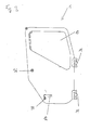
- FIGS. 1 and 2 show an interior view of a vehicle door for an unillustrated armored vehicle with the inner lining removed.
- the vehicle door 1 has an armored glass pane 10 and is connected via the hinges 11 to the vehicle.
- the vehicle door 1 has an internal handle 2, by means of which the door lock 42 can be opened via the linkage 51.
- the armored vehicle door as in Fig. 3 shown, also a handle 12 which is arranged on a lock cylinder 34 and in the same way on the door lock 42 via a linkage 33, inter alia consisting of driving element 50, rotary member 52, rotary member 53, spring 55, linkage 56 and slot 57 acts.
- the vehicle door 1 can be opened by a predetermined angle until a damping element 27, which is arranged on a stop device 5, abuts against a door stop 28.
- the vehicle door 1 on a brake device comprising a gas spring 3.
- the gas spring 3 is connected at one end to a vehicle-fixed rod 6 via a rotary bearing 35 to the vehicle.
- a door movement is braked in the unventilated state of the gas spring 3.
- the braking device is designed such that it can be released manually.
- it has an actuating device which comprises the handles 2 and 12.
- the handles 2 and 12 are mechanically connected to an intermediate element 21 which rotatably follows a rotational movement of the handles 2 and 12 follows.
- the intermediate element 21 has an actuating surface which comes into contact with a predetermined angle of pivoting of the intermediate element 21 with a lever 22 which is arranged on the vehicle door 1 via the pivot bearing 25.
- a push rod 23 is moved, which abuts against a stop element 24 of an actuating element 16.
- the actuating element 16 is rotatably mounted on the vehicle door 1 via a pivot bearing 17.
- the actuating element 16 in this case has an actuating switch 9, which abuts upon rotation of the actuating element 16 against a pin-shaped release element 8, which aerates the gas spring 3.
- actuating switch 9 which abuts upon rotation of the actuating element 16 against a pin-shaped release element 8, which aerates the gas spring 3.
- the braking effect on the door movement is reduced, so that the door 1 can be moved by the operation of the handles 2 and 12.
- the vehicle door 1 also has a brake release device, which reduces the braking effect of the brake device on the vehicle door movement in the last movement section of a movement of the vehicle door 1 in the closed position.
- the brake release device in this case comprises a telescopic linkage 4, which is connected at one end portion to the vehicle via the vehicle-fixed rod 6 by means of a pivot bearing 32.
- a cam is hinged as a switching element 7.
- the switching element 7 is connected via a pivot bearing 14 with the vehicle door 1.
- the pivot bearing 14 is in this case arranged eccentrically to the switching element 7.
- the switching element 7 has a switching cam 31, which at a rotation of the switching element 7 by a predetermined angular amount of a driving piece 18, which is arranged on an arm 19 of the actuating element 16, entrains and thus causes a rotational movement of the actuating element 16.
- the actuating element 16 can in turn act on the pin-shaped release element 8 and reduce the braking effect.
- the switching element 7 is configured and arranged such that the switching cam 31 only acts on the driving piece 18 when the door is in the last movement portion of a movement of the vehicle door 1 in the closed position.
- This last movement section extends from the closed position over an angular range of 0 ° to 30 °.
- the brake device is thus released automatically via the brake release device in the last movement section.
- the angle range from 0 ° to 30 ° there is no braking effect of the gas spring 3 on the vehicle door movement.
- the brake release device is structurally and / or spatially separated from the brake device.
- the brake release device acts on the brake device from the outside.
- the brake release device is releasably connected to the brake device, so that an interchangeability of the individual components is given.
- the brake release device is adjustable with respect to the angular range. By adaptation of the switching element 7, for example by displacement of the axis of rotation or by changing the geometry of the switching element 7, the angular range of the last movement section can be adjusted in a simple manner.
Landscapes
- Engineering & Computer Science (AREA)
- General Engineering & Computer Science (AREA)
- Mechanical Engineering (AREA)
- Closing And Opening Devices For Wings, And Checks For Wings (AREA)
- Braking Arrangements (AREA)
Abstract
Description
- Die Erfindung betrifft eine Fahrzeugtür für gepanzerte Fahrzeuge mit einer eine Fahrzeugtürbewegung bremsenden Bremsvorrichtung. Eine solche Bremsvorrichtung wird verwendet, um die Tür, die bei gepanzerten Fahrzeugen ein hohes Eigengewicht aufweisen kann, gegen ungewollte Bewegungen zu sichern, beispielsweise in dem Fall, in dem das Fahrzeug quer zu einem Hang steht. Eine solche Bremsvorrichtung kann somit auch einen Schutz vor Einklemmungen bieten.
- Die Bremsvorrichtung kann mittels einer Betätigungsvorrichtung freigegeben werden, die zumeist manuell betätigbar ist und einen Türgriff umfasst. Bei Betätigung des Türgriffes kann die Bremsvorrichtung freigegeben werden, so dass eine Person die Türe öffnen oder schließen kann. In der Regel muss die Betätigungsvorrichtung für eine Fahrzeugtürbewegung dauerhaft betätigt werden, so dass ein Loslassen der Betätigungsvorrichtung zu einer Bremsung der Fahrzeugtürbewegung führt.
- Nachteilig an einer solchen Ausgestaltung ist, dass eine Person die Fahrzeugtür nur dann schließen kann, wenn die Betätigungsvorrichtung während der gesamten Schließbewegung betätigt ist. Es hat sich jedoch gezeigt, dass Personen dazu neigen, den Türgriff im letzten Bewegungsabschnitt der Bewegung der Fahrzeugtür in die Schließstellung loszulassen, damit die Tür mit Schwung zufällt. Beim Loslassen der Betätigungsvorrichtung wirkt allerdings wiederum die Bremsvorrichtung bremsend auf die Fahrzeugtürbewegung, so dass ein Schließen der Fahrzeugtür verhindert wird.
- Die Erfindung hat die Aufgabe, eine Fahrzeugtür für gepanzerte Fahrzeuge derart auszugestalten, dass ein Schließen der Fahrzeugtür in einfacher Weise ermöglicht wird.
- Die Erfindung löst die Aufgabe mit den Merkmalen aus dem kennzeichnenden Teil des Patentanspruchs 1. Vorteilhafte Weiterbildungen sind Bestandteil der abhängigen Ansprüche.
- Ein Grundgedanke der Erfindung liegt darin, die Fahrzeugtür derart auszugestalten, dass die Bremswirkung der Bremsvorrichtung auf die Fahrzeugtürbewegung im letzten Bewegungsabschnitt einer Bewegung der Fahrzeugtür in die Schließstellung verringert ist. Der letzte Bewegungsabschnitt kann sich hierbei ausgehend von der Schließstellung über einen vorgegebenen Winkelbereich von 0° bis 45°, insbesondere von 0° bis 30°, erstrecken.
- Die Bremsvorrichtung kann eine Gasdruckfeder umfassen, die zur Freigabe über ein an der Gasdruckfeder angeordnetes Freigabeelement belüftbar ist. Die Bremsvorrichtung kann ferner zum Freigeben der Fahrzeugtür mittels einer Betätigungsvorrichtung manuell freigebbar sein. Die Betätigungsvorrichtung kann hierbei einen oder mehrere Türgriffe sowie ein Betätigungselement umfassen, welches auf ein Freigabeelement zur Freigabe der Bremsvorrichtung wirkt.
- Die Fahrzeugtür kann des Weiteren eine Bremsfreigabevorrichtung aufweisen, die im letzten Bewegungsabschnitt der Bewegung der Fahrzeugtür in die Schließstellung die Bremswirkung der Bremsvorrichtung verringert und insbesondere automatisch freigibt. Die Bremsfreigabevorrichtung kann hierbei ein Schaltelement, insbesondere eine Kurvenscheibe, umfassen, welches bei einer Fahrzeugtürbewegung bewegt wird und welches im letzten Bewegungsabschnitt auf ein Freigabeelement zur Freigabe der Bremsvorrichtung wirkt.
- Die Bremsfreigabevorrichtung kann ferner eine Teleskopanlenkung umfassen, die zur Anlenkung des Schaltelements an einem Endabschnitt mit dem Schaltelement verbunden ist und die am anderen Endabschnitt mit dem Fahrzeug insbesondere über ein Drehlager verbindbar ist. Bei einer Schließbewegung der Fahrzeugtür verringert sich die Länge der Teleskopanlenkung, so dass das Schaltelement, welches insbesondere mit der Fahrzeugtür über ein Drehlager verbunden ist, bewegt wird. Das Schaltelement kann einen Schaltnocken aufweisen, welcher derart am Schaltelement angeordnet ist, dass er erst im letzten Bewegungsabschnitt auf ein Freigabeelement einwirkt. Das Schaltelement kann ferner exzentrisch gelagert sein und wiederum derart ausgestaltet sein, dass erst im letzten Bewegungsabschnitt eine Wirkung auf ein Freigabeelement entsteht. Bei einer bevorzugten Ausgestaltung wirkt das Schaltelement auf das Betätigungselement, welches auch die manuelle Freigabe der Bremsvorrichtung bewirkt.
- Die Betätigungsvorrichtung kann ferner derart ausgestaltet sein, dass sie zum manuellen Freigeben der Bremsvorrichtung dauerhaft zu betätigen ist.
- Bei einer besonders bevorzugten Ausgestaltung ist die Fahrzeugtürbewegung im letzten Bewegungsabschnitt ungebremst. Der letzte Bewegungsabschnitt verläuft somit in einem Leerwinkel. Die Fahrzeugtür kann hierbei durch den eigenen Schwung schließen oder in einfacher Weise zugedrückt oder zugezogen werden.
- Ein vorteilhaftes Ausführungsbeispiel der Erfindung wird anhand der
Figuren 1 bis 8 beschrieben. Es zeigen: - Fig. 1
- eine Innenansicht einer Fahrzeugtür;
- Fig. 2
- einen vergrößerten Ausschnitt der Fahrzeugtür nach
Fig. 1 ; - Fig. 3
- eine Außenansicht der Fahrzeugtür nach
Fig. 1 ; - Fig. 4
- den Ausschnitt der Fahrzeugtür nach
Fig. 2 in einer perspektivischen Darstellung; - Fig. 5
- die Fahrzeugtür nach
Fig. 1 in der Draufsicht; - Fig. 6
- einen vergrößerten Ausschnitt der
Fig. 5 ; - Fig. 7
- einen vergrößerten Ausschnitt der
Fig. 1 in einer perspektivischen Darstellung und - Fig. 8
- einen vergrößerten Ausschnitt der
Fig. 7 . - Die
Figuren 1 und2 zeigen eine Innenansicht einer Fahrzeugtüre für ein nicht dargestelltes gepanzertes Fahrzeug mit abgenommener Innenverblendung. Die Fahrzeugtür 1 weist eine Panzerglasscheibe 10 auf und ist über die Scharniere 11 mit dem Fahrzeug verbunden. Die Fahrzeugtür 1 weist einen innenliegenden Handgriff 2 auf, mittels dessen das Türschloss 42 über das Gestänge 51 geöffnet werden kann. Von außen weist die gepanzerte Fahrzeugtür, wie inFig. 3 dargestellt, ebenfalls einen Handgriff 12 auf, der über einem Schließzylinder 34 angeordnet ist und der in gleicher Weise auf das Türschloss 42 über ein Gestänge 33 u. a. bestehend aus Mitnahmeelement 50, Drehstück 52, Drehelement 53, Feder 55, Gestänge 56 und Langloch 57 wirkt. - Die Fahrzeugtür 1 kann um einen vorgegebenen Winkel geöffnet werden, bis ein Dämpfungselement 27, welches an einer Anschlagvorrichtung 5 angeordnet ist, gegen einen Türanschlag 28 stößt.
- Wie in
Fig. 4 dargestellt, weist die Fahrzeugtür 1 eine Bremsvorrichtung auf, die eine Gasdruckfeder 3 umfasst. Die Gasdruckfeder 3 ist an einem Ende mit einer fahrzeugfesten Stange 6 über eine Drehlagerung 35 mit dem Fahrzeug verbunden. Somit wird im unbelüfteten Zustand der Gasdruckfeder 3 eine Türbewegung gebremst. - Die Bremsvorrichtung ist derart ausgestaltet, dass sie manuell freigegeben werden kann. Hierzu weist sie eine Betätigungsvorrichtung auf, die die Griffe 2 und 12 umfasst. Die Griffe 2 und 12 sind mechanisch mit einem Zwischenelement 21 verbunden, welches drehbar gelagert einer Drehbewegung der Griffe 2 und 12 folgt. Das Zwischenelement 21 weist eine Betätigungsfläche auf, die bei einem vorgegebenen Schwenkwinkel des Zwischenelements 21 mit einem Hebel 22, der über das Drehlager 25 an der Fahrzeugtür 1 angeordnet ist, in Kontakt kommt. Durch die Bewegung des Hebels 22 wird eine Schubstange 23 bewegt, welche gegen ein Anschlagelement 24 eines Betätigungselementes 16 anschlägt. Wie in
Fig. 8 dargestellt, ist das Betätigungselement 16 über ein Drehlager 17 drehbar an der Fahrzeugtür 1 angeordnet. Das Betätigungselement 16 weist hierbei einen Betätigungsschalter 9 auf, welcher bei einer Drehung des Betätigungselementes 16 gegen ein stiftförmiges Freigabeelement 8 stößt, welches die Gasdruckfeder 3 belüftet. Durch die Belüftung der Gasdruckfeder 3 wird die Bremswirkung auf die Türbewegung verringert, so dass die Tür 1 über die Betätigung der Griffe 2 und 12 bewegt werden kann. - Die Fahrzeugtür 1 weist zudem eine Bremsfreigabevorrichtung auf, welche die Bremswirkung der Bremsvorrichtung auf die Fahrzeugtürbewegung im letzten Bewegungsabschnitt einer Bewegung der Fahrzeugtür 1 in die Schließstellung verringert. Die Bremsfreigabevorrichtung umfasst hierbei eine Teleskopanlenkung 4, welche an einem Endabschnitt mit dem Fahrzeug über die fahrzeugfeste Stange 6 mittels eines Drehlagers 32 verbunden ist. Am anderen Endabschnitt der Teleskopanlenkung 4 ist eine Kurvenscheibe als Schaltelement 7 angelenkt. Das Schaltelement 7 ist über ein Drehlager 14 mit der Fahrzeugtür 1 verbunden. Das Drehlager 14 ist hierbei exzentrisch zum Schaltelement 7 angeordnet. Über das Drehlager 15 wird somit eine Bewegung der Teleskopanlenkung 4 in eine Drehbewegung des Schaltelementes 7 umgewandelt. Das Schaltelement 7 weist einen Schaltnocken 31 auf, welcher bei einer Drehung des Schaltelementes 7 um einen vorgegebenen Winkelbetrag ein Mitnahmestück 18, welches an einem Arm 19 des Betätigungselementes 16 angeordnet ist, mitnimmt und somit eine Drehbewegung des Betätigungselementes 16 bewirkt. Das Betätigungselement 16 kann wiederum auf das stiftförmige Freigabeelement 8 einwirken und die Bremswirkung reduzieren.
- Das Schaltelement 7 ist derart ausgestaltet und angeordnet, dass der Schaltnocken 31 nur dann auf das Mitnahmestück 18 einwirkt, wenn sich die Tür im letzten Bewegungsabschnitt einer Bewegung der Fahrzeugtür 1 in die Schließstellung befindet. Dieser letzte Bewegungsabschnitt erstreckt sich ausgehend von der Schließstellung über einen Winkelbereich von 0° bis 30°.
- Die Bremsvorrichtung wird somit über die Bremsfreigabevorrichtung im letzten Bewegungsabschnitt automatisch freigegeben. Im Winkelbereich von 0° bis 30° liegt keine Bremswirkung der Gasdruckfeder 3 auf die Fahrzeugtürbewegung vor.
- Die Bremsfreigabevorrichtung ist baulich und/oder räumlich von der Bremsvorrichtung getrennt. Die Bremsfreigabevorrichtung wirkt von außen auf die Bremsvorrichtung. Die Bremsfreigabevorrichtung ist lösbar mit der Bremsvorrichtung verbunden, so dass eine Austauschbarkeit der einzelnen Komponenten gegeben ist. Die Bremsfreigabevorrichtung ist hinsichtlich des Winkelbereichs einstellbar. Durch Anpassung des Schaltelements 7, beispielsweise durch Versatz der Drehachse oder durch Veränderung der Geometrie des Schaltelements 7, kann in einfacher Weise der Winkelbereich des letzten Bewegungsabschnitts eingestellt werden.
-
- 1
- Fahrzeugtür
- 2
- Handgriff
- 3
- Gasdruckfeder
- 4
- Teleskopanlenkung
- 5
- Anschlagvorrichtung
- 6
- fahrzeugfeste Stange
- 7
- Schaltelement
- 8
- Freigabeelement
- 9
- Betätigungsschalter
- 10
- Panzerglasscheibe
- 11
- Türscharnier
- 12
- Handgriff
- 13
- Schließfeder
- 14
- Drehlager
- 15
- Drehlager
- 16
- Betätigungselement
- 17
- Drehlager
- 18
- Mitnahmestück
- 19
- Arm
- 20
- Feder
- 21
- Zwischenelement
- 22
- Hebel
- 23
- Schubstange
- 24
- Anschlagstück
- 25
- Drehlager
- 26
- Anschlagstück
- 27
- Dämpfungselement
- 28
- Türanschlag
- 29
- Griffmechanik
- 31
- Schaltnocken
- 32
- Drehlager
- 33
- Gestänge
- 34
- Schließzylinder
- 35
- Drehlager
- 36
- Notentriegelung
- 40a,b
- Minenschutzriegel
- 41a,b
- Halteelement
- 42
- Türschloss
- 50
- Mitnahmeelement
- 51
- Gestänge
- 52
- Drehstück
- 53
- Drehelement
- 55
- Feder
- 56
- Gestänge
- 57
- Langloch
Claims (14)
- Fahrzeugtür für gepanzerte Fahrzeuge, mit einer eine Fahrzeugtürbewegung bremsenden Bremsvorrichtung (3), dadurch gekennzeichnet, dass die Bremswirkung der Bremsvorrichtung (3) auf die Fahrzeugtürbewegung im letzten Bewegungsabschnitt einer Bewegung der Fahrzeugtür in die Schließstellung verringert ist.
- Fahrzeugtür nach Anspruch 1, dadurch gekennzeichnet, dass sich der letzte Bewegungsabschnitt ausgehend von der Schließstellung über einen Winkelbereich von 0° bis 45°, insbesondere von 0° bis 30°, erstreckt.
- Fahrzeugtür nach einem der vorhergehenden Ansprüche, dadurch gekennzeichnet, dass die Bremsvorrichtung eine Gasdruckfeder (3) umfasst, die zur Freigabe über ein Freigabeelement (8) belüftbar ist.
- Fahrzeugtür nach einem der vorhergehenden Ansprüche, dadurch gekennzeichnet, dass die Bremsvorrichtung zum Freigeben der Fahrzeugtür (1) mittels einer Betätigungsvorrichtung (2, 9, 12, 16, 21, 22, 23, 24, 26) manuell freigebbar ist.
- Fahrzeugtür nach Anspruch 4, dadurch gekennzeichnet, dass Betätigungsvorrichtung einen oder mehrere Türgriffe (2, 12) und ein Betätigungselement (16) umfasst, welches auf ein Freigabeelement (8) zur Freigabe der Bremsvorrichtung (3) wirkt.
- Fahrzeugtür nach Anspruch 4 oder 5, dadurch gekennzeichnet, dass die Betätigungsvorrichtung (2, 9, 12, 16, 21, 22, 23, 24, 26) zum manuellen Freigeben der Bremsvorrichtung (3) dauerhaft betätigt werden muss.
- Fahrzeugtür nach einem der vorhergehenden Ansprüche, dadurch gekennzeichnet, dass sie eine, insbesondere einstellbare, Bremsfreigabevorrichtung (4, 7, 9, 16, 18, 19, 31) aufweist, die im letzten Bewegungsabschnitt die Bremsvorrichtung (3) automatisch freigibt.
- Fahrzeugtür nach Anspruch 7, dadurch gekennzeichnet, dass die Bremsfreigabevorrichtung ein Schaltelement (7), insbesondere eine Kurvenscheibe, umfasst, das bei einer Fahrzeugtürbewegung bewegt wird und das im letzten Bewegungsabschnitt auf ein Freigabeelement (8) zur Freigabe der Bremsvorrichtung (3) wirkt.
- Fahrzeugtür nach Anspruch 8, dadurch gekennzeichnet, dass die Bremsfreigabevorrichtung eine Teleskopanlenkung (4) umfasst, die zur Anlenkung des Schaltelements (7) an einem Endabschnitt mit dem Schaltelement (7) verbunden ist und die am anderen Endabschnitt mit dem Fahrzeug, insbesondere über ein Drehlager (32), verbindbar ist.
- Fahrzeugtür nach einem der Ansprüche 8 oder 9, dadurch gekennzeichnet, dass das Schaltelement (7) einen Schaltnocken (31) aufweist.
- Fahrzeugtür nach einem der Ansprüche 8 bis 10, dadurch gekennzeichnet, dass das Schaltelement (7) exzentrisch gelagert ist.
- Fahrzeugtür nach Anspruch 5 und einem der Ansprüche 7 bis 11, dadurch gekennzeichnet, dass das Schaltelement (7) auf das Betätigungselement (16) wirkt.
- Fahrzeugtür nach einem der vorhergehenden Ansprüche, dadurch gekennzeichnet, dass die Fahrzeugtürbewegung im letzten Bewegungsabschnitt ungebremst ist.
- Fahrzeugtür nach einem der vorhergehenden Ansprüche, dadurch gekennzeichnet, dass sie eine Schließfeder (13) zur Unterstützung der Schließbewegung der Fahrzeugtür (1) aufweist.
Applications Claiming Priority (1)
| Application Number | Priority Date | Filing Date | Title |
|---|---|---|---|
| DE200810039510 DE102008039510A1 (de) | 2008-08-23 | 2008-08-23 | Fahrzeugtür für gepanzerte Fahrzeuge |
Publications (3)
| Publication Number | Publication Date |
|---|---|
| EP2157394A2 true EP2157394A2 (de) | 2010-02-24 |
| EP2157394A3 EP2157394A3 (de) | 2012-10-17 |
| EP2157394B1 EP2157394B1 (de) | 2016-07-20 |
Family
ID=41037821
Family Applications (1)
| Application Number | Title | Priority Date | Filing Date |
|---|---|---|---|
| EP09166802.0A Active EP2157394B1 (de) | 2008-08-23 | 2009-07-30 | Fahrzeugtür für gepanzerte Fahrzeuge |
Country Status (2)
| Country | Link |
|---|---|
| EP (1) | EP2157394B1 (de) |
| DE (1) | DE102008039510A1 (de) |
Citations (1)
| Publication number | Priority date | Publication date | Assignee | Title |
|---|---|---|---|---|
| DE102005005891A1 (de) | 2005-02-09 | 2006-08-24 | Hs Genion Gmbh | Tür mit Türbremse |
Family Cites Families (5)
| Publication number | Priority date | Publication date | Assignee | Title |
|---|---|---|---|---|
| DE3629250A1 (de) * | 1986-08-28 | 1988-03-03 | Stabilus Gmbh | Stufenlos blockierbare verstelleinrichtung |
| DE4403703C1 (de) * | 1994-02-07 | 1995-04-13 | Daimler Benz Ag | Türfeststellvorrichtung für eine Fahrzeugtür |
| DE29517724U1 (de) * | 1995-11-09 | 1996-12-19 | Fürst, Peter, 63927 Bürgstadt | Arretierungseinrichtung für Kraftfahrzeugtüren |
| DE102004061687A1 (de) * | 2004-12-22 | 2006-07-06 | Daimlerchrysler Ag | Fahrzeugtür mit einer Abbremsfunktion |
| US7556304B2 (en) * | 2006-03-14 | 2009-07-07 | Strattec Power Access Llc | Actuation device for vehicle panel |
-
2008
- 2008-08-23 DE DE200810039510 patent/DE102008039510A1/de not_active Withdrawn
-
2009
- 2009-07-30 EP EP09166802.0A patent/EP2157394B1/de active Active
Patent Citations (1)
| Publication number | Priority date | Publication date | Assignee | Title |
|---|---|---|---|---|
| DE102005005891A1 (de) | 2005-02-09 | 2006-08-24 | Hs Genion Gmbh | Tür mit Türbremse |
Also Published As
| Publication number | Publication date |
|---|---|
| EP2157394A3 (de) | 2012-10-17 |
| DE102008039510A1 (de) | 2010-02-25 |
| EP2157394B1 (de) | 2016-07-20 |
Similar Documents
| Publication | Publication Date | Title |
|---|---|---|
| EP2157396B1 (de) | Fahrzeugtür für gepanzerte Fahrzeuge mit einem Minenschutzriegel | |
| DE2813347C2 (de) | Verschluß an einer Notausgangstür | |
| EP0792404B1 (de) | Pneumatisches türschloss | |
| EP3049598B1 (de) | Kraftfahrzeugtürgriff | |
| DE102014212863B4 (de) | Klappensteuerung | |
| WO2006119530A1 (de) | Holster für handfeuerwaffen | |
| EP2094923B1 (de) | Verriegelungsvorrichtung für schiebetüren von luftfahrzeugen, insbesondere von hubschraubern | |
| EP3396088A1 (de) | Fahrzeugtürgriff | |
| EP2094924B1 (de) | Türschloss für türen von luftfahrzeugen, insbesondere von hubschraubern | |
| DE102014114945A1 (de) | Kraftfahrzeugtürschloss | |
| DE2805639B1 (de) | Vorrichtung zur Sicherung der Verriegelungsstellung von durch Drehsaeulen betaetigten Fahrzeugtueren | |
| DE102009007686A1 (de) | Manuelle Feststellvorrichtung für höhenverstellbare hintere Fahrzeugfenster, feststellbare Kurbelvorrichtung und Kraftfahrzeuge hiermit | |
| DE10114438A1 (de) | Schließeinrichtung mit Zuziehhilfe | |
| DE102010041913A1 (de) | Entriegelungsvorrichtung | |
| EP2157394B1 (de) | Fahrzeugtür für gepanzerte Fahrzeuge | |
| EP3179021B1 (de) | Türgriffanordnung für ein kraftfahrzeug | |
| DE102013222053A1 (de) | Schließeinrichtung für eine Kraftfahrzeughaube und Verfahren | |
| WO2018145693A1 (de) | Kraftfahrzeugtürschloss | |
| DE102010053179A1 (de) | Kraftfahrzeugtürverschluss | |
| DE10339542B4 (de) | Kraftfahrzeugtürverschluss | |
| DE4339654A1 (de) | Kraftfahrzeugtürverschluß | |
| EP3118401A1 (de) | Kantriegel | |
| EP2993287B1 (de) | Druckstange zur Betätigung eines Türverschlusses | |
| EP2683891A2 (de) | Möbelschloss | |
| WO2006084445A2 (de) | Tür mit türbremse |
Legal Events
| Date | Code | Title | Description |
|---|---|---|---|
| PUAI | Public reference made under article 153(3) epc to a published international application that has entered the european phase |
Free format text: ORIGINAL CODE: 0009012 |
|
| AK | Designated contracting states |
Kind code of ref document: A2 Designated state(s): AT BE BG CH CY CZ DE DK EE ES FI FR GB GR HR HU IE IS IT LI LT LU LV MC MK MT NL NO PL PT RO SE SI SK SM TR |
|
| PUAL | Search report despatched |
Free format text: ORIGINAL CODE: 0009013 |
|
| AK | Designated contracting states |
Kind code of ref document: A3 Designated state(s): AT BE BG CH CY CZ DE DK EE ES FI FR GB GR HR HU IE IS IT LI LT LU LV MC MK MT NL NO PL PT RO SE SI SK SM TR |
|
| RIC1 | Information provided on ipc code assigned before grant |
Ipc: E05C 17/22 20060101ALI20120910BHEP Ipc: F41H 7/04 20060101ALI20120910BHEP Ipc: F41H 5/22 20060101AFI20120910BHEP |
|
| 17P | Request for examination filed |
Effective date: 20130410 |
|
| 17Q | First examination report despatched |
Effective date: 20130719 |
|
| GRAP | Despatch of communication of intention to grant a patent |
Free format text: ORIGINAL CODE: EPIDOSNIGR1 |
|
| RIC1 | Information provided on ipc code assigned before grant |
Ipc: E05C 17/30 20060101ALN20160115BHEP Ipc: F41H 5/22 20060101AFI20160115BHEP Ipc: E05B 85/22 20140101ALN20160115BHEP Ipc: F41H 7/04 20060101ALI20160115BHEP |
|
| INTG | Intention to grant announced |
Effective date: 20160202 |
|
| GRAS | Grant fee paid |
Free format text: ORIGINAL CODE: EPIDOSNIGR3 |
|
| GRAA | (expected) grant |
Free format text: ORIGINAL CODE: 0009210 |
|
| AK | Designated contracting states |
Kind code of ref document: B1 Designated state(s): AT BE BG CH CY CZ DE DK EE ES FI FR GB GR HR HU IE IS IT LI LT LU LV MC MK MT NL NO PL PT RO SE SI SK SM TR |
|
| REG | Reference to a national code |
Ref country code: GB Ref legal event code: FG4D Free format text: NOT ENGLISH |
|
| REG | Reference to a national code |
Ref country code: CH Ref legal event code: EP |
|
| REG | Reference to a national code |
Ref country code: IE Ref legal event code: FG4D Free format text: LANGUAGE OF EP DOCUMENT: GERMAN |
|
| REG | Reference to a national code |
Ref country code: AT Ref legal event code: REF Ref document number: 814456 Country of ref document: AT Kind code of ref document: T Effective date: 20160815 |
|
| REG | Reference to a national code |
Ref country code: FR Ref legal event code: PLFP Year of fee payment: 8 |
|
| REG | Reference to a national code |
Ref country code: DE Ref legal event code: R096 Ref document number: 502009012839 Country of ref document: DE |
|
| REG | Reference to a national code |
Ref country code: LT Ref legal event code: MG4D |
|
| REG | Reference to a national code |
Ref country code: NL Ref legal event code: MP Effective date: 20160720 |
|
| PG25 | Lapsed in a contracting state [announced via postgrant information from national office to epo] |
Ref country code: BE Free format text: LAPSE BECAUSE OF NON-PAYMENT OF DUE FEES Effective date: 20160731 |
|
| PG25 | Lapsed in a contracting state [announced via postgrant information from national office to epo] |
Ref country code: NO Free format text: LAPSE BECAUSE OF FAILURE TO SUBMIT A TRANSLATION OF THE DESCRIPTION OR TO PAY THE FEE WITHIN THE PRESCRIBED TIME-LIMIT Effective date: 20161020 Ref country code: HR Free format text: LAPSE BECAUSE OF FAILURE TO SUBMIT A TRANSLATION OF THE DESCRIPTION OR TO PAY THE FEE WITHIN THE PRESCRIBED TIME-LIMIT Effective date: 20160720 Ref country code: LT Free format text: LAPSE BECAUSE OF FAILURE TO SUBMIT A TRANSLATION OF THE DESCRIPTION OR TO PAY THE FEE WITHIN THE PRESCRIBED TIME-LIMIT Effective date: 20160720 Ref country code: NL Free format text: LAPSE BECAUSE OF FAILURE TO SUBMIT A TRANSLATION OF THE DESCRIPTION OR TO PAY THE FEE WITHIN THE PRESCRIBED TIME-LIMIT Effective date: 20160720 Ref country code: FI Free format text: LAPSE BECAUSE OF FAILURE TO SUBMIT A TRANSLATION OF THE DESCRIPTION OR TO PAY THE FEE WITHIN THE PRESCRIBED TIME-LIMIT Effective date: 20160720 Ref country code: IS Free format text: LAPSE BECAUSE OF FAILURE TO SUBMIT A TRANSLATION OF THE DESCRIPTION OR TO PAY THE FEE WITHIN THE PRESCRIBED TIME-LIMIT Effective date: 20161120 |
|
| PG25 | Lapsed in a contracting state [announced via postgrant information from national office to epo] |
Ref country code: PT Free format text: LAPSE BECAUSE OF FAILURE TO SUBMIT A TRANSLATION OF THE DESCRIPTION OR TO PAY THE FEE WITHIN THE PRESCRIBED TIME-LIMIT Effective date: 20161121 Ref country code: ES Free format text: LAPSE BECAUSE OF FAILURE TO SUBMIT A TRANSLATION OF THE DESCRIPTION OR TO PAY THE FEE WITHIN THE PRESCRIBED TIME-LIMIT Effective date: 20160720 Ref country code: PL Free format text: LAPSE BECAUSE OF FAILURE TO SUBMIT A TRANSLATION OF THE DESCRIPTION OR TO PAY THE FEE WITHIN THE PRESCRIBED TIME-LIMIT Effective date: 20160720 Ref country code: GR Free format text: LAPSE BECAUSE OF FAILURE TO SUBMIT A TRANSLATION OF THE DESCRIPTION OR TO PAY THE FEE WITHIN THE PRESCRIBED TIME-LIMIT Effective date: 20161021 Ref country code: SE Free format text: LAPSE BECAUSE OF FAILURE TO SUBMIT A TRANSLATION OF THE DESCRIPTION OR TO PAY THE FEE WITHIN THE PRESCRIBED TIME-LIMIT Effective date: 20160720 Ref country code: LV Free format text: LAPSE BECAUSE OF FAILURE TO SUBMIT A TRANSLATION OF THE DESCRIPTION OR TO PAY THE FEE WITHIN THE PRESCRIBED TIME-LIMIT Effective date: 20160720 |
|
| REG | Reference to a national code |
Ref country code: DE Ref legal event code: R097 Ref document number: 502009012839 Country of ref document: DE |
|
| PG25 | Lapsed in a contracting state [announced via postgrant information from national office to epo] |
Ref country code: RO Free format text: LAPSE BECAUSE OF FAILURE TO SUBMIT A TRANSLATION OF THE DESCRIPTION OR TO PAY THE FEE WITHIN THE PRESCRIBED TIME-LIMIT Effective date: 20160720 Ref country code: EE Free format text: LAPSE BECAUSE OF FAILURE TO SUBMIT A TRANSLATION OF THE DESCRIPTION OR TO PAY THE FEE WITHIN THE PRESCRIBED TIME-LIMIT Effective date: 20160720 Ref country code: MC Free format text: LAPSE BECAUSE OF FAILURE TO SUBMIT A TRANSLATION OF THE DESCRIPTION OR TO PAY THE FEE WITHIN THE PRESCRIBED TIME-LIMIT Effective date: 20160720 |
|
| REG | Reference to a national code |
Ref country code: IE Ref legal event code: MM4A |
|
| PLBE | No opposition filed within time limit |
Free format text: ORIGINAL CODE: 0009261 |
|
| STAA | Information on the status of an ep patent application or granted ep patent |
Free format text: STATUS: NO OPPOSITION FILED WITHIN TIME LIMIT |
|
| PG25 | Lapsed in a contracting state [announced via postgrant information from national office to epo] |
Ref country code: SK Free format text: LAPSE BECAUSE OF FAILURE TO SUBMIT A TRANSLATION OF THE DESCRIPTION OR TO PAY THE FEE WITHIN THE PRESCRIBED TIME-LIMIT Effective date: 20160720 Ref country code: CZ Free format text: LAPSE BECAUSE OF FAILURE TO SUBMIT A TRANSLATION OF THE DESCRIPTION OR TO PAY THE FEE WITHIN THE PRESCRIBED TIME-LIMIT Effective date: 20160720 Ref country code: SM Free format text: LAPSE BECAUSE OF FAILURE TO SUBMIT A TRANSLATION OF THE DESCRIPTION OR TO PAY THE FEE WITHIN THE PRESCRIBED TIME-LIMIT Effective date: 20160720 Ref country code: DK Free format text: LAPSE BECAUSE OF FAILURE TO SUBMIT A TRANSLATION OF THE DESCRIPTION OR TO PAY THE FEE WITHIN THE PRESCRIBED TIME-LIMIT Effective date: 20160720 Ref country code: BG Free format text: LAPSE BECAUSE OF FAILURE TO SUBMIT A TRANSLATION OF THE DESCRIPTION OR TO PAY THE FEE WITHIN THE PRESCRIBED TIME-LIMIT Effective date: 20161020 |
|
| 26N | No opposition filed |
Effective date: 20170421 |
|
| REG | Reference to a national code |
Ref country code: FR Ref legal event code: PLFP Year of fee payment: 9 |
|
| PG25 | Lapsed in a contracting state [announced via postgrant information from national office to epo] |
Ref country code: IE Free format text: LAPSE BECAUSE OF NON-PAYMENT OF DUE FEES Effective date: 20160730 |
|
| PG25 | Lapsed in a contracting state [announced via postgrant information from national office to epo] |
Ref country code: SI Free format text: LAPSE BECAUSE OF FAILURE TO SUBMIT A TRANSLATION OF THE DESCRIPTION OR TO PAY THE FEE WITHIN THE PRESCRIBED TIME-LIMIT Effective date: 20160720 Ref country code: LU Free format text: LAPSE BECAUSE OF NON-PAYMENT OF DUE FEES Effective date: 20160730 |
|
| PG25 | Lapsed in a contracting state [announced via postgrant information from national office to epo] |
Ref country code: CY Free format text: LAPSE BECAUSE OF FAILURE TO SUBMIT A TRANSLATION OF THE DESCRIPTION OR TO PAY THE FEE WITHIN THE PRESCRIBED TIME-LIMIT Effective date: 20160720 Ref country code: HU Free format text: LAPSE BECAUSE OF FAILURE TO SUBMIT A TRANSLATION OF THE DESCRIPTION OR TO PAY THE FEE WITHIN THE PRESCRIBED TIME-LIMIT; INVALID AB INITIO Effective date: 20090730 |
|
| PG25 | Lapsed in a contracting state [announced via postgrant information from national office to epo] |
Ref country code: MK Free format text: LAPSE BECAUSE OF FAILURE TO SUBMIT A TRANSLATION OF THE DESCRIPTION OR TO PAY THE FEE WITHIN THE PRESCRIBED TIME-LIMIT Effective date: 20160720 Ref country code: MT Free format text: LAPSE BECAUSE OF FAILURE TO SUBMIT A TRANSLATION OF THE DESCRIPTION OR TO PAY THE FEE WITHIN THE PRESCRIBED TIME-LIMIT Effective date: 20160720 Ref country code: TR Free format text: LAPSE BECAUSE OF FAILURE TO SUBMIT A TRANSLATION OF THE DESCRIPTION OR TO PAY THE FEE WITHIN THE PRESCRIBED TIME-LIMIT Effective date: 20160720 |
|
| REG | Reference to a national code |
Ref country code: FR Ref legal event code: PLFP Year of fee payment: 10 |
|
| PGFP | Annual fee paid to national office [announced via postgrant information from national office to epo] |
Ref country code: GB Payment date: 20200724 Year of fee payment: 12 Ref country code: FR Payment date: 20200727 Year of fee payment: 12 |
|
| PGFP | Annual fee paid to national office [announced via postgrant information from national office to epo] |
Ref country code: IT Payment date: 20200731 Year of fee payment: 12 Ref country code: AT Payment date: 20200720 Year of fee payment: 12 Ref country code: CH Payment date: 20200724 Year of fee payment: 12 |
|
| REG | Reference to a national code |
Ref country code: CH Ref legal event code: PL |
|
| REG | Reference to a national code |
Ref country code: AT Ref legal event code: MM01 Ref document number: 814456 Country of ref document: AT Kind code of ref document: T Effective date: 20210730 |
|
| GBPC | Gb: european patent ceased through non-payment of renewal fee |
Effective date: 20210730 |
|
| PG25 | Lapsed in a contracting state [announced via postgrant information from national office to epo] |
Ref country code: LI Free format text: LAPSE BECAUSE OF NON-PAYMENT OF DUE FEES Effective date: 20210731 Ref country code: GB Free format text: LAPSE BECAUSE OF NON-PAYMENT OF DUE FEES Effective date: 20210730 Ref country code: CH Free format text: LAPSE BECAUSE OF NON-PAYMENT OF DUE FEES Effective date: 20210731 Ref country code: AT Free format text: LAPSE BECAUSE OF NON-PAYMENT OF DUE FEES Effective date: 20210730 |
|
| PG25 | Lapsed in a contracting state [announced via postgrant information from national office to epo] |
Ref country code: FR Free format text: LAPSE BECAUSE OF NON-PAYMENT OF DUE FEES Effective date: 20210731 |
|
| PG25 | Lapsed in a contracting state [announced via postgrant information from national office to epo] |
Ref country code: IT Free format text: LAPSE BECAUSE OF NON-PAYMENT OF DUE FEES Effective date: 20210730 |
|
| P01 | Opt-out of the competence of the unified patent court (upc) registered |
Effective date: 20230517 |
|
| REG | Reference to a national code |
Ref country code: DE Ref legal event code: R081 Ref document number: 502009012839 Country of ref document: DE Owner name: KNDS DEUTSCHLAND GMBH & CO. KG, DE Free format text: FORMER OWNER: KRAUSS-MAFFEI WEGMANN GMBH & CO. KG, 80997 MUENCHEN, DE |
|
| PGFP | Annual fee paid to national office [announced via postgrant information from national office to epo] |
Ref country code: DE Payment date: 20250731 Year of fee payment: 17 |