EP3396088A1 - Fahrzeugtürgriff - Google Patents
Fahrzeugtürgriff Download PDFInfo
- Publication number
- EP3396088A1 EP3396088A1 EP18152137.8A EP18152137A EP3396088A1 EP 3396088 A1 EP3396088 A1 EP 3396088A1 EP 18152137 A EP18152137 A EP 18152137A EP 3396088 A1 EP3396088 A1 EP 3396088A1
- Authority
- EP
- European Patent Office
- Prior art keywords
- handle
- vehicle door
- lever
- movement
- mass balance
- Prior art date
- Legal status (The legal status is an assumption and is not a legal conclusion. Google has not performed a legal analysis and makes no representation as to the accuracy of the status listed.)
- Granted
Links
- 230000033001 locomotion Effects 0.000 claims abstract description 74
- 230000001133 acceleration Effects 0.000 claims abstract description 12
- 230000007246 mechanism Effects 0.000 claims description 43
- 230000008878 coupling Effects 0.000 claims description 23
- 238000010168 coupling process Methods 0.000 claims description 23
- 238000005859 coupling reaction Methods 0.000 claims description 23
- 230000005540 biological transmission Effects 0.000 description 9
- 238000013461 design Methods 0.000 description 6
- 238000013459 approach Methods 0.000 description 3
- 238000010276 construction Methods 0.000 description 3
- 230000004048 modification Effects 0.000 description 2
- 238000012986 modification Methods 0.000 description 2
- 238000012546 transfer Methods 0.000 description 2
- 230000006978 adaptation Effects 0.000 description 1
- 230000004888 barrier function Effects 0.000 description 1
- 230000001419 dependent effect Effects 0.000 description 1
- 238000011161 development Methods 0.000 description 1
- 230000018109 developmental process Effects 0.000 description 1
- 230000000694 effects Effects 0.000 description 1
- 230000003993 interaction Effects 0.000 description 1
- 238000002955 isolation Methods 0.000 description 1
- 238000004519 manufacturing process Methods 0.000 description 1
- 230000001960 triggered effect Effects 0.000 description 1
Images


Classifications
-
- E—FIXED CONSTRUCTIONS
- E05—LOCKS; KEYS; WINDOW OR DOOR FITTINGS; SAFES
- E05B—LOCKS; ACCESSORIES THEREFOR; HANDCUFFS
- E05B77/00—Vehicle locks characterised by special functions or purposes
- E05B77/02—Vehicle locks characterised by special functions or purposes for accident situations
- E05B77/04—Preventing unwanted lock actuation, e.g. unlatching, at the moment of collision
- E05B77/06—Preventing unwanted lock actuation, e.g. unlatching, at the moment of collision by means of inertial forces
-
- E—FIXED CONSTRUCTIONS
- E05—LOCKS; KEYS; WINDOW OR DOOR FITTINGS; SAFES
- E05B—LOCKS; ACCESSORIES THEREFOR; HANDCUFFS
- E05B85/00—Details of vehicle locks not provided for in groups E05B77/00 - E05B83/00
- E05B85/10—Handles
- E05B85/103—Handles creating a completely closed wing surface
-
- E—FIXED CONSTRUCTIONS
- E05—LOCKS; KEYS; WINDOW OR DOOR FITTINGS; SAFES
- E05B—LOCKS; ACCESSORIES THEREFOR; HANDCUFFS
- E05B85/00—Details of vehicle locks not provided for in groups E05B77/00 - E05B83/00
- E05B85/10—Handles
- E05B85/107—Pop-out handles, e.g. sliding outwardly before rotation
-
- E—FIXED CONSTRUCTIONS
- E05—LOCKS; KEYS; WINDOW OR DOOR FITTINGS; SAFES
- E05B—LOCKS; ACCESSORIES THEREFOR; HANDCUFFS
- E05B81/00—Power-actuated vehicle locks
- E05B81/54—Electrical circuits
- E05B81/64—Monitoring or sensing, e.g. by using switches or sensors
- E05B81/76—Detection of handle operation; Detection of a user approaching a handle; Electrical switching actions performed by door handles
-
- E—FIXED CONSTRUCTIONS
- E05—LOCKS; KEYS; WINDOW OR DOOR FITTINGS; SAFES
- E05B—LOCKS; ACCESSORIES THEREFOR; HANDCUFFS
- E05B81/00—Power-actuated vehicle locks
- E05B81/54—Electrical circuits
- E05B81/90—Manual override in case of power failure
Definitions
- the invention is directed to a vehicle door handle comprising a handle carrier and a handle movably mounted on the handle, wherein the handle can assume at least a rest position and a standby position, and wherein the handle when installed in a vehicle door in the rest position aligned flush with the outside of the vehicle door is arranged and arranged in the standby position for actuation relative to the outside of the vehicle door issued in a Ausstellraum.
- a vehicle door handle in which the handle in its rest position is flush with the outside of the vehicle door, is known from the prior art.
- vehicle door handles there are a variety of different constructions and embodiments.
- the inventive design of a vehicle door handle refers to such structures in which the handle support on the back of the vehicle door, ie, inside the motor vehicle, is attached.
- the handle mounted on the handle support is in such embodiments usually protruding from the vehicle door and disturbs both the aesthetic impression of the vehicle and the vehicle aerodynamics.
- vehicle door handles are therefore known from the prior art, in which the handle in its rest position, ie in which it is not needed, approximately flush with the outside of the vehicle door, so flush or flush, runs.
- Such a handle is for opening the vehicle door or a vehicle-mounted lock in a standby position can be converted, in which the handle protrudes from the outside of the vehicle door.
- the handle is extended by a motor when a legitimate operator is the vehicle approaches. As soon as the handle is no longer needed, it returns to the rest position and thus disappears into the body so as not to create any air resistance.
- the invention is based on a prior art, in which such flush-mounted vehicle door handles have no crash barrier or similar security elements that should ensure in the event of a vehicle accident that the vehicle door remains closed and is not opened undesirable due to acting on the handle acceleration forces.
- This results in particular for flush-fitted vehicle door handles the problem of very low crash safety when the handle is in different positions, such as in the rest position or the ready position. Consequently, there is the danger that in the case of flush vehicle door handles, small and unfavorably directed acceleration forces can cause the vehicle door to open.
- the invention has for its object to provide a solution that provides a vehicle door handle in a structurally simple manner that is inexpensive to manufacture and also has improved safety in the event of a vehicle accident, to prevent unwanted opening of the vehicle door.
- a mass balance element is coupled to the handle and is pivotally mounted on the handle support about a pivot axis, wherein upon movement of the handle from the rest position to the standby position, the handle mass balancing element from a basic position in pivots an operating position, and wherein the mass balance element with its mass and / or its geometry is designed so adapted to the handle, that the mass balance element both in the rest position and in the ready position of the handle upon exposure to a the Ausstellraum directed acceleration force acting on the handle and generates the handle at least at a further movement in Ausstellraum hindering counter-torque.
- the mass balance element holds the handle at least either in the rest position or in the ready position, wherein the mass balance element, for example, a movement of the handle in one of the Ausstellcardi opposite direction, ie in the direction of rest, can cause when the handle is in the standby position ,
- the handle next to the rest position and the standby position can also occupy an actuating position, in which the handle is then moved by an operator from the standby position further in Ausstellcardi to effect a door opening operation.
- the invention provides a vehicle door handle is provided which is characterized by a functional design and has a compact and inexpensive construction.
- a balancing mass in the form of the mass balance element is kinematically coupled as an additional component to the handle.
- the mass balance element is moved by the handle, wherein the kinematics of the mass balance element is designed such that the mass balance element in both the rest position and the standby position, a "closing moment", i. generates a counter-torque at a critical lateral force acting in Ausstellraum acceleration force.
- the invention provides in an embodiment that the mass balance element with a first distance to Pivoting axis arranged balancing mass body and spaced a second distance from the pivot axis arranged coupling device for movement coupling with the handle.
- the mass balance element may be disk-shaped or designed in the manner of a lever, wherein it is rotatably mounted on the pivot axis and both the coupling device and the balancing mass body are arranged at predetermined intervals to the pivot axis on the mass balance element.
- the first distance is smaller than the second distance.
- the balancing mass body is mounted substantially closer to the pivot axis than the coupling device, so that a strong acceleration of the mass balance element in the event of a crash at acting acceleration forces is possible.
- the invention provides in a further embodiment, that the compensation mass body and the coupling device are formed and arranged with respect to the pivot axis at different circumferential positions on the mass balance element.
- the mass balance element is designed as a two-sided lever which is pivotally mounted about the pivot axis on the handle support, wherein a first lever arm of the two-sided lever, the coupling device for movement coupling the handle has and a second lever arm of the two-sided lever having the balancing mass body.
- the mass balance element could also be designed as an angle lever.
- the coupling device is designed as a guide recess, in which a movement pin coupled to the handle is arranged, which is movably guided along the guide recess during a movement of the handle.
- the invention provides in a further embodiment, that the guide recess is formed to extend radially with respect to the pivot axis.
- the guide recess therefore extends radially to the pivot axis or radially away from the pivot axis.
- the movement pin is integrally formed on a lever mechanism rotatably mounted on the handle carrier via an axis of rotation, which movably fixes the handle to the handle carrier, the mass balance element being motion-coupled to the handle via the lever mechanism. It is particularly advantageous if the lever mechanism is further coupled with a Bowden cable system, so that the mass balance element can be effective directly on the component, which is responsible for opening the door.
- the invention provides in an embodiment that the pivoting angle between the basic position and the intermediate position to the pivot angle between the intermediate position and the operating position is carried out symmetrically. In this way, the tight space conditions and a large pivoting of the handle in their movement from the rest position into the ready position bill taken into account.
- FIG. 1 is a vehicle or motor vehicle 1 in the form of a car exemplified, which in the example of four vehicle doors 2 (two of which are from FIG. 1 apparent), which can be opened via a respective vehicle door handle 3 and in particular by means of a handle 4 of the vehicle door handle 3.
- the vehicle doors 2 are firmly closed by a respective door lock 5 and can be opened or unlocked from the outside only via a respective movement of the handle 4.
- This movement on the handle 4 consists of a pulling movement, wherein the corresponding movement of the handle 4 is transmitted via a Bowden cable system 6 to the corresponding lock 5.
- the associated vehicle door 2 can then open, wherein in the case of a current-driven normal operation, a slight pulling movement sufficient so that the Bowden cable system 6 is electrically operated to unlock the door lock 5.
- the vehicle door handle 3 is designed such that a manual unlocking of the door lock 5 and thus a manual opening of the vehicle door 2 by an operator effected actuation of the handle 4 is possible, which is characterized by a required, increased actuation force in Compared to the necessary operating force in normal operation.
- FIG. 2 shows in perspective view one of the vehicle doors 2 and serving to open the vehicle door 2 handle 4.
- the handle 4 - when installing the vehicle door handle 3 in the vehicle door 2 - approximately flush with the outside 7 of the vehicle door 2, ie flush or flush mounted, arranged.
- the handle 4 is in a rest position in which it is not needed.
- the handle 4 From the in FIG. 2 shown rest position (see also FIGS. 16 and 17 ) is the handle 4 in a standby position (see FIGS. 18 and 19 ), in which it protrudes relative to the outside 7 of the vehicle door 2. Accordingly, the handle 4 is arranged protruding from the vehicle door 2 in its ready position.
- proximity sensors or other sensors may be provided to bring the handle 4 from the flush or flush position to the ready position as soon as an operator approaches the vehicle door handle 3 or the handle 4.
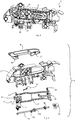
- FIGS. 3 to 10 the vehicle door handle 3 is shown in different views and for different structural details.
- the vehicle door handle 3 has in addition to the handle 4, a handle support 8, which is fastened in the installed state on the inside of the vehicle door 2 and serves, inter alia, the handle 4 to store such that the handle 4 in its rest position flush with the outside 7 of the Vehicle door 2 is arranged to extend and is movable to operate in its standby position, wherein the handle 4 protrudes in its standby position relative to the outside 7 of the vehicle door 2 and can be engaged and operated by the operator to open the vehicle door 2.
- FIG. 3 shows the vehicle door handle 3 in a perspective front view, wherein the handle 4 is in its rest position.
- the handle 4 is in its rest position.
- FIG. 4 shown rear view of the vehicle door handle 3 illustrates the compact and a small space consuming design of the vehicle door handle 3.
- This compact design is inter alia by a complex lever system 9 (see, for example FIGS. 6 and 7 ), which comprises a lever element 10, a lever mechanism 11 and a motion transmission bracket 12, such as the single part illustration in FIG FIG. 5 shows.
- the lever member 10, the lever mechanism 11 and the movement transmission bracket 12 are on stored the handle support 8, wherein the handle 4 is connected by means of the lever system 9 on the handle support 8.
- the vehicle door handle 3 comprises a vehicle door opening lever 14, an actuating element 15 and a mass balance element 16, which are also mounted in each case on the handle support 8.
- a first longitudinal end 17 of the handle 4 is connected via the lever member 10 with the handle support 8, wherein the lever member 10 is attached to a rotatably mounted on the handle support 8 lever pivot axis 18.
- the lever member 10 which is formed one arm and angled, motion-coupled to the handle 4 when the lever member 10 rotates about the lever rotation axis 18.
- a second longitudinal end 19 of the handle 4 is connected via the lever mechanism 11 to the handle support 8, wherein the lever mechanism 11 is rotatably supported via a rotation axis 21 on the handle support 8, so that the second longitudinal end 19 of the handle 4 via the lever mechanism 11 on the handle support 8 is movably mounted.
- the lever mechanism 11 comprises a handle lever 20 connected to the handle 4 and a lever body 22 rotatably mounted on a rotation axis 21 (see, for example FIG. 8 ).
- the handle lever 20 is formed one arm and angled and rotatably connected to the second longitudinal end 19 of the handle 4. Between the two sections of the two-part rotary axis 21 of the handle lever 20 is arranged, whereby a very compact design can be realized.
- the handle lever 20 is further rotatably connected to the lever body 22, wherein the lever body 22 has a passive lever 23 and an active lever 24 (see, for example FIG. 8 ).
- the passive lever 23 and the active lever 24 are mounted on the mounted on the handle support 8 axis of rotation 21 and rotate at a movement of the handle 4 from the rest position to the standby position together, whereas upon actuation of the handle 4 from the standby position, a relative movement between the Passive lever 23 and the active lever 24 takes place.
- the handle lever 20 is rotatably connected to the passive lever 23, wherein the passive lever 23 is rotatably connected to the rotation axis 21.
- the active lever 24 is rotatably connected to the rotation axis 21, so that the active lever 24 is rotatably mounted relative to the rotation axis 21 at this.
- the special feature of the lever mechanism 11 is the aspect that the passive lever 23 and the active lever 24, which form the lever body 22, act as a single lever in the movement of the handle 4 from the rest position to the standby position and rotate together about the rotation axis 21, whereas for actuation operations of the handle 4 effected by the operator in the standby position, the passive lever 23 and the active lever 24 rotate relative to each other about the rotation axis 21 and accordingly act as separate levers.
- the lever element 10 is connected in a motion-coupled manner via the movement transmission bracket 12 to the lever mechanism 11 (see, for example, FIG FIG. 6 ).
- a first longitudinal end 25 of thesupersübertragungsbügels 12 spaced from the lever pivot axis 18 to the lever member 10 is rotatably connected.
- a second longitudinal end 26 of theabsolusübertragungsbügels 12 is spaced from the axis of rotation 21 to the lever mechanism 11 rotatably connected.
- the lever member 10 and the lever mechanism 11 out of engagement with the eastsübertragungsbügel 12, so that in the rest position of the handle 4, the lever member 10 and the lever mechanism 11 are decoupled from the movement transmission bracket 12.
- the movement transmission bracket 12 In the rest position of the handle 4, the movement transmission bracket 12 is arranged in a position from which he is movable to an unlocking position to unlock the door lock 5.
- the motor-driven actuator 15 is decoupled in the rest position of the handle 4 of the lever member 10 and the lever mechanism 11 and has no fixed connection to the lever member 10 and the lever mechanism 16.
- the adjusting element 15 is consequently not in engagement with the lever element 10 and with the lever mechanism 11 when the handle 4 is arranged in its rest position.
- the motor-driven actuator 15 is mounted on the handle support 8, wherein a motor drive axis of an electric motor drives and rotates the actuator 15.
- a vehicle control controller In a current-driven normal operation of the vehicle door handle 3, an approach of an authorized operator to the vehicle 1 is detected by a vehicle control controller, whereupon a signal from the vehicle control controller is sent to the electric motor, which then begins its operation and rotates the actuator 15 via the motor drive axis.
- the electric motor is energized for a predetermined period of time and rotates the actuator 15 about the motor drive axis by a predetermined angle which is in a range of 90 ° to 130 °.
- the actuator 15 is disc-shaped with a non-uniform edge 27 (see, for example FIGS. 9 and 10 ) and rotatably mounted on the handle support 8 via the motor drive shaft. Upon a rotational movement of the actuating element 15 about the motor drive axis, the non-uniform edge 27 cooperates with the lever element 10 in such a way that a rotation of the actuating element 15 leads to a uniform handle disengaging movement.
- the motor-driven actuator 15 presses an edge portion with increasing radius against the lever member 10 and moves the handle 4 via the lever member 10 from the rest position to its standby position.
- the uniform Griffausstellmony the motor-driven actuator 15 then stops when on formed with the adjusting element 15 edge portion with a constant radius 27a (see, for example FIG. 9 ) rests against the lever member 10, thereby ensuring that the first longitudinal end 17 of the handle 4 is arranged exposed to the outside 7 of the vehicle door 2.
- the movement transmission bracket 12 cooperates with the active lever 24 and rotates the active lever 24 about the rotation axis 21.
- the passive lever 23 and the active lever 24 rotate as the common lever body 22 about the rotation axis 21.
- the transmitted by the movement of the movement transmission bracket 12 on the lever mechanism 11 Force causes the handle lever 20 moves away due to its coupling with the handle 4 of the rotation axis 21, whereby the second longitudinal end 19 of the handle 4 is issued exhibited from the outside 7 of the vehicle door 2.
- the connection of the second longitudinal end 20 of the handle 4 is thus formed in the manner of a toggle lever.
- the actuator 15 is further rotated by an operation of the handle 4, whereby the Entriegelungskontur 28 the vehicle door opening lever 14 in the direction of the lever mechanism 11 urges and thus the Bowden cable system 6 is actuated to unlock the door by the Bowden cable lever 14 b by the movement of the Vehicle door opening lever 14 is moved.
- the handle 4 can also be pulled so far in Ausstellcardi by increased force by the operator that on the lever mechanism 11 of the vehicle door opening lever 14 manually from the operator moved and thus the Bowden cable system 6 is actuated.
- FIGS. 11 to 19 show structural details that are related to the mass balance element 16.
- the mass balance element 16 of the vehicle door handle 3 according to the invention serves to ensure that the handle 4 both in the rest position as well as in the standby position upon exposure to a in a Ausstellcardi 29 (see, for example, arrow in FIG FIG. 17 ) directed acceleration force is prevented from moving in the direction of the Ausstelltechnik 29 by the mass balance element 16 generates a corresponding counter-torque 41.
- the mass balance element 16 is pivotally mounted on the handle support 8 via a pivot axis 30, wherein the mass balance element 16 is further coupled to the handle 4.
- the mass balance element 16 has a balancing mass body 31 and a coupling device 32 for movement coupling with the handle 4, wherein the balancing mass body 31 is disposed at a first distance 33 to the pivot axis 30 on the mass balance element 16 and the coupling device at a second distance 34 to Pivoting axis 30 is arranged on the mass balance element 16.
- the first distance 33 is smaller than the second distance 34 is formed.
- the illustration in FIG. 12 It can be seen that the balancing mass body 31 and the coupling device 32 are formed and arranged with respect to the pivot axis 30 at different circumferential positions on the mass balance element 16.
- the Mass balance element 16 is formed as a two-sided lever 35.
- This two-sided lever 35 is pivotally mounted about the pivot axis 30 on the handle carrier 8, wherein a first lever arm 35a of the two-sided lever 35 has the coupling means 32 for movement coupling with the handle 4 and a second lever arm 35b of the two-sided lever 35 has the balancing mass body 31 , Accordingly, the length 36 of the second lever arm 35b is shorter than the length 37 of the first lever arm 35a.
- the coupling device 32 is formed on the first lever arm 35a as a guide recess 38.
- the guide recess 38 serves that in it a coupled to the handle 4 movement pin 39 (see, for example FIGS. 8 and 11 ), wherein the movement pin 39 is movably guided during a movement of the handle 4 along the guide recess 38.
- the movement pin 39 is integrally formed on the pivoting about the axis of rotation 21 on the handle support 8 mounted lever mechanism 11 which the handle 4 movably attached to the handle support 8. Consequently, the mass balance element 16 is coupled in terms of movement via the lever mechanism 11 to the handle 4.
- the movement pin 39 is formed on a rotatable about the axis of rotation 21 lever 40 of the lever mechanism 11, wherein also existing levers of the lever mechanism 11 with appropriate modification / adaptation could be used for this purpose. How further the FIG. 12 can be seen, the guide recess 38 is formed with respect to the pivot axis 30 extending radially.
- FIGS. 13 to 15 is the interaction of lever mechanism 11 and mass balance element 16 during a movement of the handle 4 from the rest position (see FIG. 13 ) via an intermediate position (see FIG. 14 ) in the ready position (see FIG. 15 ), for illustration in the FIGS. 16 and 17 Views are shown in which the handle 4 is arranged in the rest position is, and in the FIGS. 18 and 19 Views are shown in which the handle 4 is arranged in the standby position.
- the mass balance element 16 from its basic position (see FIG. 13 ) via an intermediate position (see FIG. 14 ) in its operating position (see FIG. 15 ) pans.
- This movement is effected by the coupling with the lever 40 of the lever mechanism 11 and consequently by the movement of the handle 4, so that the handle 4, the mass balance element 16 moves, which is advantageous in terms of the mobility of the mass balance element 16.
- the mass balance element 16 is thus coupled in a motion-coupled manner with the handle 4 and assumes a corresponding position (basic position, operating position) in dependence on the position of the handle 4.
- the two-sided lever 35 passes through the intermediate position lying between the home position and the operating position (see FIG. 14 ).
- mass balance element 16 is arranged in line with the lever 40 of the lever mechanism 11.
- the swing angle 42a between the home position and the intermediate position is made symmetrical to the swing angle 42b between the intermediate position and the operating position, as schematically illustrated in FIG FIG. 14 is shown.
- the mass balance element 16 is formed so matched to the handle 4 with its mass and geometry that the mass balance element 16 both in the rest position and in the ready position of the handle 4 by acting in the Ausstellraum 29 directed acceleration force, such as occurs in the case of a vehicle accident, an acting on the handle 4 and the handle 4 at least at a further movement in Ausstellraum 29 preventing counter-torque 41 generated.
- the counter-moment 41 counteracts Clockwise in the FIGS. 13, 14 and 15 , so that the lever 40 is held by the influence of the counter-torque 41 at least in its position shown in the figures or from the in the FIGS. 14 and 15 shown positions back to the in FIG. 13 shown position (by rotation of the lever 40 in a clockwise direction with respect to FIG. 15 ) is moved, in which the handle 4 is arranged in its rest position.
- the mass balance element 16 prevents further movement of the handle 4 in the Ausstellraum 29th
- the present invention relates to a vehicle door handle 3, which has the handle support 8 and the handle 4 on the handle 8 movably mounted handle.
- the handle 4 occupy at least the rest position and the standby position, but also be moved beyond the standby position when actuated by an operator.
- the handle 4 is arranged flush with the outside 7 of the vehicle door 2 when installed in a vehicle door 2 in the rest position and arranged in the standby position for actuation relative to the outside 7 of the vehicle door 2 in the direction of deployment.
- the mass balance element 16 is provided, which is coupled to the handle 4 and is pivotably mounted on the handle support 8 about a pivot axis 30.
- the mass balance element 16 Upon movement of the handle 4 from the rest position to the standby position, the handle 4 pivots the mass balance element 16 from the basic position to the operating position.
- the mass balance element 16 is designed with its mass and / or its geometry so matched to the handle 4, that the mass balance element 16 both in the rest position and in the ready position of the handle 4 when acting in the Ausstellraum 29 accelerating force acting on the handle 4 and the handle 4 at least at a further movement in Ausstellraum 29 preventing counter-torque 41 generated.
Landscapes
- Lock And Its Accessories (AREA)
Abstract
Description
- Die Erfindung richtet sich auf einen Fahrzeugtürgriff, aufweisend einen Griffträger und eine an dem Griffträger bewegbar gelagerte Handhabe, wobei die Handhabe zumindest eine Ruhestellung und eine Bereitschaftsstellung einnehmen kann, und wobei die Handhabe bei Einbau in eine Fahrzeugtür in Ruhestellung strakbündig mit der Außenseite der Fahrzeugtür verlaufend angeordnet ist und in Bereitschaftsstellung zur Betätigung gegenüber der Außenseite der Fahrzeugtür in eine Ausstellrichtung ausgestellt angeordnet ist.
- Ein Fahrzeugtürgriff, bei dem die Handhabe in ihrer Ruhestellung strakbündig mit der Außenseite der Fahrzeugtür verläuft, ist aus dem Stand der Technik bekannt. Für solche bekannten Fahrzeugtürgriffe gibt es eine Vielzahl von verschiedenen Konstruktionen und Ausführungsformen. Die erfindungsgemäße Ausführung eines Fahrzeugtürgriffes bezieht sich auf solche Konstruktionen, bei denen der Griffträger auf der Rückseite der Fahrzeugtür, d.h. innenseitig des Kraftfahrzeugs, befestigt wird. Die an dem Griffträger angebrachte Handhabe steht bei solchen Ausführungsformen üblicherweise von der Fahrzeugtür hervor und stört sowohl den ästhetischen Eindruck des Fahrzeugs als auch die Fahrzeug-Aerodynamik. Um diese Nachteile zu vermeiden, sind daher aus dem Stand der Technik Fahrzeugtürgriffen bekannt, bei denen die Handhabe in ihrer Ruhestellung, d.h. in welcher sie nicht gebraucht wird, in etwa bündig zur Außenseite der Fahrzeugtür, also strakbündig bzw. flächenbündig, verläuft. Eine solche Handhabe ist zum Öffnen der Fahrzeugtür oder eines fahrzeugseitigen Schlosses in eine Bereitschaftsstellung überführbar, in welcher die Handhabe gegenüber der Außenseite der Fahrzeugtür vorsteht. Dabei wird die Handhabe motorisch ausgefahren, wenn sich ein legitimierter Bediener dem Fahrzeug nähert. Sobald die Handhabe nicht mehr gebraucht wird, fährt sie wieder in die Ruhestellung und verschwindet somit in der Karosserie, um keinen Luftwiderstand zu erzeugen.
- Die Erfindung geht von einem Stand der Technik aus, bei dem solche flächenbündigen Fahrzeugtürgriffe keine Crashsperre oder ähnliche Sicherheitselemente aufweisen, die im Fall eines Fahrzeugunfalls sicherstellen sollen, dass die Fahrzeugtür geschlossen bleibt und nicht unerwünscht aufgrund von an der Handhabe angreifenden Beschleunigungskräften geöffnet wird. Dabei ergibt sich insbesondere für flächenbündige Fahrzeugtürgriffe das Problem einer sehr geringen Crashsicherheit, wenn sich die Handhabe in unterschiedlichen Stellungen, wie zum Beispiel in der Ruhestellung oder der Bereitschaftsstellung, befindet. Folglich besteht die Gefahr, dass bei flächenbündigen Fahrzeugtürgriffen geringe und ungünstig gerichtete Beschleunigungskräfte ein Öffnen der Fahrzeugtür bewirken können.
- Der Erfindung liegt die Aufgabe zugrunde eine Lösung zu schaffen, die auf konstruktiv einfache Weise einen Fahrzeugtürgriff bereitstellt, der kostengünstig in seiner Herstellung ist und der darüber hinaus eine verbesserte Sicherheit im Fall eines Fahrzeugunfalls aufweist, um ein unerwünschtes Öffnen der Fahrzeugtür zu verhindern.
- Bei einem Fahrzeugtürgriff der eingangs genannten Art wird die Aufgabe dadurch gelöst, dass ein Massenausgleichselement mit der Handhabe gekoppelt ist und am Griffträger um eine Schwenkachse schwenkbar gelagert ist, wobei bei Bewegung der Handhabe aus der Ruhestellung in die Bereitschaftsstellung die Handhabe das Massenausgleichselement aus einer Grundposition in eine Betriebsposition schwenkt, und wobei das Massenausgleichselement mit seiner Masse und/oder seiner Geometrie derart auf die Handhabe abgestimmt ausgebildet ist, dass das Massenausgleichselement sowohl in Ruhestellung als auch in Bereitschaftsstellung der Handhabe bei Einwirkung einer in die Ausstellrichtung gerichteten Beschleunigungskraft ein auf die Handhabe wirkendes und die Handhabe zumindest an einer weiteren Bewegung in Ausstellrichtung hinderndes Gegenmoment erzeugt. Erfindungsgemäß hält das Massenausgleichselement die Handhabe zumindest entweder in der Ruhestellung oder in der Bereitschaftsstellung, wobei das Massenausgleichselement zum Beispiel auch eine Bewegung der Handhabe in eine der Ausstellrichtung entgegengesetzte Richtung, also in Richtung der Ruhestellung, bewirken kann, wenn sich die Handhabe in der Bereitschaftsstellung befindet. Erfindungsgemäß kann die Handhabe neben der Ruhestellung und der Bereitschaftsstellung auch eine Betätigungsstellung einnehmen, bei welcher die Handhabe dann von einem Bediener aus der Bereitschaftsstellung heraus weiter in Ausstellrichtung bewegt wird, um einen Türöffnungsvorgang zu bewirken.
- Vorteilhafte und zweckmäßige Ausgestaltungen und Weiterbildungen der Erfindung ergeben sich aus den Unteransprüchen.
- Durch die Erfindung wird ein Fahrzeugtürgriff zur Verfügung gestellt, der sich durch eine funktionsgerechte Konstruktion auszeichnet und einen kompakten und kostengünstigen Aufbau aufweist. Bei dem Fahrzeugtürgriff gemäß der Erfindung wird eine Ausgleichsmasse in Form des Massenausgleichselements als zusätzliches Bauteil an die Handhabe kinematisch angekoppelt. Während der Bewegung der Handhabe aus der Ruhestellung in die Bereitschaftsstellung wird das Massenausgleichselement von der Handhabe mitbewegt, wobei die Kinematik des Massenausgleichselements derart gestaltet ist, dass das Massenausgleichselement sowohl in der Ruhestellung als auch in der Bereitschaftsstellung ein "schließendes Moment", d.h. ein Gegenmoment bei einer kritischen lateralen in Ausstellrichtung wirkenden Beschleunigungskraft erzeugt.
- Die Erfindung sieht in Ausgestaltung vor, dass das Massenausgleichselement einen mit einem ersten Abstand zur Schwenkachse angeordneten Ausgleichsmasse-Körper und eine mit einem zweiten Abstand zur Schwenkachse beabstandet angeordnete Kopplungseinrichtung zur Bewegungskopplung mit der Handhabe aufweist. Das Massenausgleichselement kann dabei scheibenförmig oder nach Art eines Hebels ausgebildete sein, wobei es an der Schwenkachse drehbar gelagert ist und sowohl die Kopplungseinrichtung als auch der Ausgleichsmasse-Körper in vorbestimmten Abständen zur Schwenkachse an dem Massenausgleichselement angeordnet ausgebildet sind.
- Zur Einhaltung der engen Bauraumbedingungen ist es in Ausgestaltung der Erfindung von Vorteil, wenn der erste Abstand kleiner ist als der zweite Abstand. Auf diese Weise ist der Ausgleichsmasse-Körper wesentlich näher an der Schwenkachse gelagert als die Kopplungseinrichtung, so dass eine starke Beschleunigung des Massenausgleichselements im Crashfall bei wirksam werdenden Beschleunigungskräften möglich ist.
- Unter Berücksichtigung der engen Bauraumbedingungen sieht die Erfindung in weiterer Ausgestaltung vor, dass der Ausgleichsmasse-Körper und die Kopplungseinrichtung mit Bezug auf die Schwenkachse an unterschiedlichen Umfangspositionen an dem Massenausgleichselement ausgebildet und angeordnet sind.
- Eine Möglichkeit zur kompakten und platzsparenden Ausbildung des Massenausgleichselements sieht die Erfindung in Ausgestaltung dadurch vor, dass das Massenausgleichselement als ein zweiseitiger Hebel ausgebildet ist, welcher um die Schwenkachse schwenkbar an dem Griffträger gelagert ist, wobei ein erster Hebelarm des zweiseitigen Hebels die Kopplungseinrichtung zur Bewegungskopplung mit der Handhabe aufweist und ein zweiter Hebelarm des zweiseitigen Hebels den Ausgleichsmasse-Körper aufweist. Im Hinblick auf eine starke Beschleunigung des Massenausgleichselements, die im Crashfall bei in Ausstellrichtung wirkenden Beschleunigungskräften erwünscht ist, sieht die Erfindung vor, dass die Länge des zweiten Hebelarms kürzer ausgebildet ist als die Länge des ersten Hebelarms. Alternativ zur Ausgestaltung eines zweiseitigen Hebels könnte das Massenausgleichselement auch als ein Winkelhebel ausgebildet sein.
- Konstruktiv besonders günstig ist es in weiterer Ausgestaltung der Erfindung, wenn die Kopplungseinrichtung als eine Führungsausnehmung ausgebildet ist, in welcher ein mit der Handhabe gekoppelter Bewegungszapfen angeordnet ist, der bei einer Bewegung der Handhabe entlang der Führungsausnehmung bewegbar geführt ist.
- Damit das Massenausgleichselement von der Handhabe mitbewegt werden kann und bei der Mitbewegung kein erhöhter Widerstand erzeugt wird, sieht die Erfindung in weiterer Ausgestaltung vor, dass die Führungsausnehmung mit Bezug auf die Schwenkachse radial verlaufend ausgebildet ist. Die Führungsausnehmung erstreckt sich also radial zur Schwenkachse hin bzw. radial von der Schwenkachse weg.
- In einer weiteren Ausgestaltung der Erfindung ist vorgesehen, dass der Bewegungszapfen an einer über eine Drehachse drehbar an dem Griffträger gelagerten Hebelmechanik angeformt ist, welche die Handhabe an dem Griffträger bewegbar befestigt, wobei das Massenausgleichselement über die Hebelmechanik mit der Handhabe bewegungsgekoppelt ist. Besonders günstig ist es dabei, wenn die Hebelmechanik ferner mit einem Bowdenzugsystem gekoppelt ist, so dass das Massenausgleichselement direkt an dem Bauteil wirksam werden kann, welches für eine Öffnung der Tür verantwortlich ist.
- Konstruktiv und kinematisch von Vorteil ist es in Ausgestaltung der Erfindung, wenn der Bewegungszapfen an einem um die Drehachse drehbaren Hebel der Hebelmechanik ausgebildet ist, wobei bei einer Bewegung der Handhabe aus der Ruhestellung in die Bereitschaftsstellung der zweiseitige Hebel eine zwischen der Grundposition und der Betriebsposition liegende Zwischenposition durchläuft, in welcher der zweiseitige Hebel in Linie zu dem Hebel der Hebelmechanik angeordnet ist.
- Schließlich sieht die Erfindung in Ausgestaltung vor, dass der Schwenkwinkel zwischen der Grundposition und der Zwischenposition zu dem Schwenkwinkel zwischen der Zwischenposition und der Betriebsposition symmetrisch ausgeführt ist. Auf diese Weise wird den engen Bauraumbedingungen und einem großen Schwenkweg der Handhabe bei ihrer Bewegung aus der Ruhestellung in die Bereitschaftsstellung Rechnung getragen.
- Es versteht sich, dass die vorstehend genannten und nachstehend noch zu erläuternden Merkmale nicht nur in der jeweils angegebenen Kombination, sondern auch in anderen Kombinationen oder in Alleinstellung verwendbar sind, ohne den Rahmen der vorliegenden Erfindung zu verlassen. Der Rahmen der Erfindung ist nur durch die Ansprüche definiert.
- Weitere Einzelheiten, Merkmale und Vorteile des Gegenstandes der Erfindung ergeben sich aus der nachfolgenden Beschreibung im Zusammenhang mit der Zeichnung, in der beispielhaft ein bevorzugtes Ausführungsbeispiel der Erfindung dargestellt ist. In der Zeichnung zeigt:
-
Figur 1 ein schematisch dargestelltes Kraftfahrzeug mit exemplarisch angedeuteten Fahrzeugtürgriffen gemäß der Erfindung, -
Figur 2 eine perspektivische Darstellung einer Fahrzeugtür mit einer strakbündig bzw. flächenbündig angeordneten Handhabe des erfindungsgemäßen Fahrzeugtürgriffs, -
Figur 3 eine perspektivische Vorderansicht auf den erfindungsgemäßen Fahrzeugtürgriff, -
Figur 4 eine perspektivische Rückansicht auf den inFigur 3 gezeigten Fahrzeugtürgriff, -
Figur 5 eine perspektivische Einzelteildarstellung des in denFiguren 3 und4 gezeigten Fahrzeugtürgriffs, -
Figur 6 eine Draufsicht auf ein Hebelsystem des Fahrzeugtürgriffs, -
Figur 7 eine Einzelteildarstellung des Hebelsystems ausFigur 6 , -
Figur 8 eine perspektivische Ansicht auf eine Hebelmechanik des Hebelsystems ausFigur 7 , -
Figur 9 eine perspektivische Draufsicht auf ein Stellelement des Fahrzeugtürgriffs, -
Figur 10 eine perspektivische Unteransicht auf das Stellelement des Fahrzeugtürgriffs, -
Figur 11 eine Perspektivansicht auf einen an der Hebelmechanik ausgebildeten Bewegungszapfen, -
Figur 12 eine Perspektivansicht auf ein Massenausgleichselement des Fahrzeugtürgriffs, -
Figur 13 eine Draufsicht auf die Hebelmechanik und das in seiner Grundposition angeordnete Massenausgleichselement in einer Ruhestellung einer Handhabe des Fahrzeugtürgriffs, -
Figur 14 eine Draufsicht auf die Hebelmechanik und das Massenausgleichselement in einer aus der Ruhestellung der Handhabe herausbewegten Stellung, -
Figur 15 eine Draufsicht auf die Hebelmechanik und das in seiner Betriebsposition angeordnete Massenausgleichselement in einer Bereitschaftsstellung der Handhabe, -
Figur 16 eine Ansicht auf den Fahrzeugtürgriff, wenn die Handhabe in ihrer Ruhestellung angeordnet ist, -
Figur 17 eine Ansicht auf den Fahrzeugtürgriff ausFigur 16 unter Weglassung eines Griffträgers des Fahrzeugtürgriffs, -
Figur 18 eine Ansicht auf den Fahrzeugtürgriff, wenn die Handhabe in ihrer Bereitschaftsstellung angeordnet ist, und -
Figur 19 eine Ansicht auf den Fahrzeugtürgriff ausFigur 18 unter Weglassung des Griffträgers des Fahrzeugtürgriffes. - In
Figur 1 ist ein Fahrzeug bzw. Kraftfahrzeug 1 in Form eines PKWs exemplarisch dargestellt, welches in dem Beispiel über vier Fahrzeugtüren 2 (zwei davon sind ausFigur 1 ersichtlich) verfügt, die über einen jeweiligen Fahrzeugtürgriff 3 und insbesondere mit Hilfe einer Handhabe 4 des Fahrzeugtürgriffes 3 geöffnet werden können. Die Fahrzeugtüren 2 werden über ein jeweiliges Türschloss 5 fest verschlossen und können von außen nur über eine jeweilige Bewegung der Handhabe 4 geöffnet bzw. entriegelt werden. Diese Bewegung an der Handhabe 4 besteht aus einer Ziehbewegung, wobei die entsprechende Bewegung der Handhabe 4 über ein Bowdenzugsystem 6 auf das entsprechende Schloss 5 übertragen wird. Durch die entsprechende Bewegung der Handhabe 4 lässt sich die zugehörige Fahrzeugtür 2 dann öffnen, wobei im Fall eines strombetriebenen Normalbetriebs eine leichte Ziehbewegung ausreicht, damit das Bowdenzugsystem 6 zum Entriegeln des Türschlosses 5 elektrisch betrieben wird. Im Fall eines stromlosen Notbetriebs ist der Fahrzeugtürgriff 3 derart ausgebildet, dass auch ein manuelles Entriegeln des Türschlosses 5 und damit ein manuelles Öffnen der Fahrzeugtür 2 durch eine von einem Bediener bewirkte Betätigung der Handhabe 4 möglich ist, die sich durch eine erforderliche, erhöhte Betätigungskraft im Vergleich zu der im Normalbetrieb notwendigen Betätigungskraft unterscheidet. - Die
Figur 2 zeigt in perspektivischer Ansicht eine der Fahrzeugtüren 2 und die zum Öffnen der Fahrzeugtür 2 dienende Handhabe 4. In derFigur 2 ist die Handhabe 4 - bei Einbau des Fahrzeugtürgriffs 3 in die Fahrzeugtür 2 - in etwa bündig zur Außenseite 7 der Fahrzeugtür 2, d.h. strakbündig bzw. flächenbündig, angeordnet. In dieser Stellung befindet sich die Handhabe 4 in einer Ruhestellung, in welcher sie nicht gebraucht wird. Aus der inFigur 2 gezeigten Ruhestellung (siehe auchFiguren 16 und 17 ) ist die Handhabe 4 in eine Bereitschaftsstellung (sieheFiguren 18 und 19 ) überführbar, in welcher sie gegenüber der Außenseite 7 der Fahrzeugtür 2 vorsteht. Demnach ist die Handhabe 4 in ihrer Bereitschaftsstellung aus der Fahrzeugtür 2 hervorstehend angeordnet. In dieser vorstehenden oder aus der Außenseite 7 ausgefahrenen Bereitschaftsstellung kann ein Bediener die Handhabe 4 hintergreifen und betätigen bzw. handhaben, um die Fahrzeugtür 2 zu öffnen bzw. das fahrzeugseitige Türschloss 5 zu entriegeln. Gemäß der vorliegenden Erfindung kann das Überführen der Handhabe 4 aus der Ruhestellung in die Bereitschaftsstellung entweder in einem strombetriebenen Normalbetrieb mittels eines geeigneten Antriebsmittels oder in einem stromlosen Notbetrieb mittels manueller Betätigung durch den Bediener erfolgen, was aber nicht Gegenstand der vorliegenden Erfindung ist, weshalb nicht näher auf den dafür vorgesehenen Mechanismus eingegangen wird. Für den strombetriebenen Normalbetrieb können Annäherungssensoren oder sonstige Sensoren vorgesehen sein, um die Handhabe 4 aus der strakbündigen bzw. flächenbündigen Ruhestellung in die Bereitschaftsstellung zu bringen, sobald ein Bediener sich dem Fahrzeugtürgriff 3 bzw. der Handhabe 4 nähert. - In den
Figuren 3 bis 10 ist der Fahrzeugtürgriff 3 in verschiedenen Ansichten und für unterschiedliche bauliche Details näher dargestellt. Der Fahrzeugtürgriff 3 weist neben der Handhabe 4 einen Griffträger 8 auf, welcher im eingebauten Zustand innenseitig an der Fahrzeugtür 2 befestigt ist und dazu dient, unter anderem die Handhabe 4 derart zu lagern, dass die Handhabe 4 in ihrer Ruhestellung strakbündig mit der Außenseite 7 der Fahrzeugtür 2 verlaufend angeordnet ist und zur Betätigung in ihre Bereitschaftsstellung bewegbar ist, wobei die Handhabe 4 in ihrer Bereitschaftsstellung gegenüber der Außenseite 7 der Fahrzeugtür 2 vorsteht und von dem Bediener zum Öffnen der Fahrzeugtür 2 hintergriffen und betätigt werden kann.Figur 3 zeigt den Fahrzeugtürgriff 3 in einer perspektivischen Vorderansicht, wobei die Handhabe 4 sich in ihrer Ruhestellung befindet. Die inFigur 4 gezeigte Rückansicht auf den Fahrzeugtürgriff 3 verdeutlicht die kompakte und einen geringen Bauraum beanspruchende Konstruktion des Fahrzeugtürgriffs 3. Dieser kompakte Aufbau wird unter anderem durch ein komplexes Hebelsystem 9 (siehe zum BeispielFiguren 6 und 7 ) realisiert, welches ein Hebelelement 10, eine Hebelmechanik 11 und einen Bewegungsübertragungsbügel 12 umfasst, wie beispielsweise die Einzelteildarstellung inFigur 5 zeigt. Das Hebelelement 10, die Hebelmechanik 11 und der Bewegungsübertragungsbügel 12 sind an dem Griffträger 8 gelagert, wobei die Handhabe 4 mittels des Hebelsystems 9 an dem Griffträger 8 angebunden ist. Wie ferner derFigur 5 anhand der Einzelteildarstellung zu entnehmen ist, umfasst der Fahrzeugtürgriff 3 einen Fahrzeugtüröffnungshebel 14, ein Stellelement 15 und ein Massenausgleichselement 16, die ebenfalls jeweils an dem Griffträger 8 gelagert sind. Ein erstes Längsende 17 der Handhabe 4 ist über das Hebelelement 10 mit dem Griffträger 8 verbunden, wobei das Hebelelement 10 an einer an dem Griffträger 8 drehbar gelagerten Hebeldrehachse 18 angebracht ist. Somit ist das Hebelelement 10, welches einarmig und abgewinkelt ausgebildet ist, mit der Handhabe 4 bewegungsgekoppelt, wenn sich das Hebelelement 10 um die Hebeldrehachse 18 dreht. Ein zweites Längsende 19 der Handhabe 4 ist über die Hebelmechanik 11 an dem Griffträger 8 angebunden, wobei die Hebelmechanik 11 über eine Drehachse 21 an dem Griffträger 8 drehbar gelagert ist, so dass das zweite Längsende 19 der Handhabe 4 über die Hebelmechanik 11 an dem Griffträger 8 bewegbar befestigt ist. - Die Hebelmechanik 11 umfasst einen mit der Handhabe 4 verbundenen Griffhebel 20 und einen drehbar an einer Drehachse 21 gelagerten Hebelkörper 22 (siehe zum Beispiel
Figur 8 ). Der Griffhebel 20 ist einarmig und abgewinkelt ausgebildet und mit dem zweiten Längsende 19 der Handhabe 4 drehbar verbunden. Zwischen den beiden Abschnitten der zweiteilig ausgeführten Drehachse 21 ist der Griffhebel 20 angeordnet, wodurch eine sehr kompakte Bauform realisierbar wird. Der Griffhebel 20 ist ferner mit dem Hebelkörper 22 drehbar verbunden, wobei der Hebelkörper 22 einen Passivhebel 23 und einen Aktivhebel 24 aufweist (siehe zum BeispielFigur 8 ). Der Passivhebel 23 und der Aktivhebel 24 sind an der an dem Griffträger 8 gelagerten Drehachse 21 gelagert und drehen bei einer Bewegung der Handhabe 4 aus der Ruhestellung in die Bereitschaftsstellung gemeinsam, wohingegen bei einer Betätigung der Handhabe 4 aus der Bereitschaftsstellung eine Relativbewegung zwischen dem Passivhebel 23 und dem Aktivhebel 24 erfolgt. Der Griffhebel 20 ist mit dem Passivhebel 23 drehbar verbunden, wobei der Passivhebel 23 mit der Drehachse 21 drehfest verbunden ist. Demgegenüber ist der Aktivhebel 24 mit der Drehachse 21 drehbar verbunden, so dass der Aktivhebel 24 relativ zu der Drehachse 21 drehbar an dieser gelagert ist. Das besondere an der Hebelmechanik 11 ist der Aspekt, dass der Passivhebel 23 und der Aktivhebel 24, die den Hebelkörper 22 bilden, bei der Bewegung der Handhabe 4 aus der Ruhestellung in die Bereitschaftsstellung als ein einziger Hebel agieren und gemeinsam um die Drehachse 21 drehen, wohingegen für vom Bediener in der Bereitschaftsstellung bewirkte Betätigungsvorgänge der Handhabe 4 der Passivhebel 23 und der Aktivhebel 24 relativ zueinander um die Drehachse 21 drehen und entsprechend als separate Hebel agieren. - Das Hebelelement 10 ist über den Bewegungsübertragungsbügel 12 mit der Hebelmechanik 11 bewegungsgekoppelt verbunden (siehe zum Beispiel
Figur 6 ). Dabei ist ein erstes Längsende 25 des Bewegungsübertragungsbügels 12 beabstandet zu der Hebeldrehachse 18 mit dem Hebelelement 10 drehbar verbunden. Ein zweites Längsende 26 des Bewegungsübertragungsbügels 12 ist beabstandet zu der Drehachse 21 mit der Hebelmechanik 11 drehbar verbunden. Wenn die Handhabe 4 aus ihrer Ruhestellung in die Bereitschaftsstellung bewegt wird, dann dreht das Hebelelement 10 im Uhrzeigersinn um die Hebeldrehachse 18, woraufhin der mit dem Hebelelement 10 gelenkig verbundene Bewegungsübertagungsbügel 12 in Richtung der Hebelmechanik 11 bzw. in Richtung des zweiten Längsendes 19 der Handhabe 4 um die Hebeldrehachse 12 bewegt wird. Ferner schwenkt das Hebelelement 10, an welchem die Handhabe 4 gelenkig angebracht ist, um die Hebeldrehachse 18, wodurch die Handhabe 4 aus ihrer flächenbündigen Ruhestellung in die Bereitschaftsstellung bewegt wird und aus der Außenseite 7 der Fahrzeugtür 2 hervorsteht. Die Bewegung des Bewegungsübertragungsbügels 12 in Richtung der Hebelmechanik 11 bzw. in Richtung des zweiten Längsendes 19 der Handhabe 4 bewirkt, dass die Hebelmechanik 11 um die Drehachse 21 herum entgegen dem Uhrzeigersinn dreht, was durch den Bewegungsübertragungsbügel 12 bewirkt wird. - Wenn die Handhabe 4 von einem Bediener aus der Bereitschaftsstellung heraus betätigt wird, ist dies eine Ziehbewegung an der Handhabe 4, wodurch diese in eine Betriebsstellung gelangt. In einer solchen Betriebsstellung ist das Hebelelement 10 weiterhin in der Position angeordnet, in welcher es in der Bereitschaftsstellung angelangt war. Es findet folglich keine weitere Drehung um die Hebeldrehachse 18 statt. Vielmehr erfolgt an der Hebelmechanik 11 eine Relativbewegung zwischen dem Passivhebel 23 und dem Aktivhebel 24, wobei dazu der Bediener eine entsprechende Kraft bei seiner Ziehbewegung an der Handhabe 4 aufbringen muss. Durch die Krafteinwirkung des Bedieners über die Handhabe 4 wird der Passivhebel 23 relativ zu dem Aktivhebel 24 bewegt, wobei der Aktivhebel 24 in seiner Position verbleibt, die er in der Bereitschaftsstellung der Handhabe 4 bereits eingenommen hat.
- Der Fahrzeugtüröffnungshebel 14, der stangenförmig ausgebildet ist, ist über zwei Gelenkpunkte 14a an dem Griffträger 8 parallel bewegbar zu dem Bewegungsübertragungsbügel 12 gelagert, wobei von einem der beiden Gelenkpunkte 14a radial ein Bodenzughebel 14b absteht (siehe
Figur 5 ), an dem ein in den Figuren nicht gezeigtes Bowdenzugkabel befestigbar ist, welches wiederum mit dem Türschloss 5 der Fahrzeugtür 2 verbunden ist und in bekannter Weise zum Entriegeln des Türschlosses 5 dient. Bei dem vorliegenden Fahrzeugtürgriff 3 stehen in der Ruhestellung der Handhabe 4 das Hebelelement 10 und die Hebelmechanik 11 außer Eingriff mit dem Bewegungsübertragungsbügel 12, so dass in der Ruhestellung der Handhabe 4 das Hebelelement 10 und die Hebelmechanik 11 von dem Bewegungsübertragungsbügel 12 entkoppelt sind. In der Ruhestellung der Handhabe 4 ist der Bewegungsübertragungsbügel 12 in einer Stellung angeordnet, aus welcher er in eine Entriegelungsposition bewegbar ist, um das Türschloss 5 zu entriegeln. - Das motorangetriebene Stellelement 15 ist in der Ruhestellung der Handhabe 4 von dem Hebelelement 10 und der Hebelmechanik 11 entkoppelt und weist keine feste Verbindung zu dem Hebelelement 10 und der Hebelmechanik 16 auf. Das Stellelement 15 steht folglich mit dem Hebelelement 10 und mit der Hebelmechanik 11 nicht in Eingriff, wenn die Handhabe 4 in ihrer Ruhestellung angeordnet ist. Das motorangetriebene Stellelement 15 ist an dem Griffträger 8 gelagert, wobei eine Motorantriebsachse eines Elektromotors das Stellelement 15 antreibt und dreht. In einem strombetriebenen Normalbetrieb des Fahrzeugtürgriffs 3 wird von einer Fahrzeugkontrollsteuerung eine Annäherung eines berechtigten Bedieners an das Fahrzeug 1 erkannt, woraufhin ein Signal von der Fahrzeugkontrollsteuerung an den Elektromotor gesandt wird, der daraufhin seinen Betrieb aufnimmt und über die Motorantriebsachse das Stellelement 15 dreht. Dabei wird der Elektromotor für eine vorbestimmte Zeitdauer bestromt und dreht das Stellelement 15 um die Motorantriebsachse um einen vorbestimmten Winkel, der in einem Bereich von 90° bis 130° liegt. Das Stellelement 15 ist scheibenförmig mit einem ungleichförmigen Rand 27 ausgebildet (siehe zum Beispiel
Figuren 9 und 10 ) und über die Motorantriebsachse drehbar an dem Griffträger 8 gelagert. Bei einer Drehbewegung des Stellelements 15 um die Motorantriebsachse wirkt der ungleichförmige Rand 27 mit dem Hebelelement 10 derart zusammen, dass eine Drehung des Stellelements 15 zu einer gleichförmigen Griffausstellbewegung führt. Bei dieser gleichförmigen Griffausstellbewegung des motorangetriebenen Stellelements 15 drückt ein Randabschnitt mit ansteigendem Radius gegen das Hebelelement 10 und bewegt die Handhabe 4 über das Hebelelement 10 aus der Ruhestellung in ihre Bereitschaftsstellung. Die gleichförmige Griffausstellbewegung des motorangetriebenen Stellelements 15 stoppt dann, wenn ein an dem Stellelement 15 ausgebildeter Randabschnitt mit konstantem Radius 27a (siehe zum BeispielFigur 9 ) an dem Hebelelement 10 anliegt, wodurch sichergestellt ist, dass das erste Längsende 17 der Handhabe 4 gegenüber der Außenseite 7 der Fahrzeugtür 2 ausgestellt angeordnet ist. - Der Bewegungsübertragungsbügel 12 wirkt mit dem Aktivhebel 24 zusammen und dreht den Aktivhebel 24 um die Drehachse 21. Dabei drehen der Passivhebel 23 und der Aktivhebel 24 als der gemeinsamer Hebelkörper 22 um die Drehachse 21. Die durch die Bewegung des Bewegungsübertragungsbügels 12 auf die Hebelmechanik 11 übertragene Kraft bewirkt, dass sich der Griffhebel 20 aufgrund seiner Kopplung mit der Handhabe 4 von der Drehachse 21 wegbewegt, wodurch das zweite Längsende 19 der Handhabe 4 aus der Außenseite 7 der Fahrzeugtür 2 ausgestellt angeordnet ist. Die Anbindung des zweiten Längsendes 20 der Handhabe 4 ist folglich nach Art eines Kniehebels ausgebildet.
- Bei der vorstehend beschriebenen Bewegung des Stellelements 27 wird lediglich die Handhabe 4 in die Bereitschaftsstellung bewegt, wohingegen der Fahrzeugöffnungshebel 14 nach wie unbewegt verbleibt. Dies ist auf eine Entriegelungskontur 28 (siehe zum Beispiel
Figur 10 ) zurückzuführen, die auf einer der beiden Seitenflächen (in dem dargestellten Ausführungsbeispiel ist der ungleichförmige Rand 27 auf der Oberseite und die Entriegelungskontur 28 auf der Unterseite des Stellelements 15 ausgebildet) des scheibenförmig ausgebildeten und motorangetriebenen Stellelements 15 ausgebildet ist. Die Entriegelungskontur 28 wirkt bei einer Bewegung des Stellelements 15, die durch eine Betätigung der Handhabe 4 durch den Bediener ausgelöst bzw. bewirkt wird. Im Normalbetrieb wird durch eine Betätigung der Handhabe 4 das Stellelement 15 weitergedreht, wodurch die Entriegelungskontur 28 den Fahrzeugtüröffnungshebel 14 in Richtung der Hebelmechanik 11 drängt und damit das Bowdenzugsystem 6 zum Entriegeln der Tür betätigt, indem der Bowdenzughebel 14b durch die Bewegung des Fahrzeugtüröffnungshebels 14 mitbewegt wird. In einem stromlosen Notbetrieb, welcher bei Ausfall der elektrischen Versorgung des Fahrzeugs 2 oder bei Ausfall des Antriebsmotors eintreten kann, kann durch erhöhte Krafteinwirkung durch den Bediener die Handhabe 4 auch soweit in Ausstellrichtung gezogen werden, dass über die Hebelmechanik 11 der Fahrzeugtüröffnungshebel 14 manuell vom Bediener bewegt und damit das Bowdenzugsystem 6 betätigt wird. - Die
Figuren 11 bis 19 zeigen bauliche Details, die in Verbindung mit dem Massenausgleichselement 16 stehen. Das Massenausgleichselement 16 des erfindungsgemäßen Fahrzeugtürgriffs 3 dient dazu, dass die Handhabe 4 sowohl in Ruhestellung als auch in Bereitschaftsstellung bei Einwirkung einer in eine Ausstellrichtung 29 (siehe zum Beispiel Pfeil inFigur 17 ) gerichteten Beschleunigungskraft an einer Bewegung in Richtung der Ausstellrichtung 29 gehindert wird, indem das Massenausgleichselement 16 ein entsprechendes Gegenmoment 41 erzeugt. Das Massenausgleichselement 16 ist über eine Schwenkachse 30 an dem Griffträger 8 schwenkbar gelagert, wobei das Massenausgleichselement 16 ferner mit der Handhabe 4 gekoppelt ist. Das Massenausgleichselement 16 weist einen Ausgleichsmasse-Körper 31 und eine Kopplungseinrichtung 32 zur Bewegungskopplung mit der Handhabe 4 auf, wobei der Ausgleichsmasse-Körper 31 in einem ersten Abstand 33 zur Schwenkachse 30 an dem Massenausgleichselement 16 angeordnet ist und die Kopplungseinrichtung in einem zweiten Abstand 34 zur Schwenkachse 30 an dem Massenausgleichselement 16 angeordnet ist. Wie ausFigur 12 ersichtlich ist, ist der erste Abstand 33 kleiner als der zweite Abstand 34 ausgebildet. Ferner ist der Darstellung inFigur 12 zu entnehmen, dass der Ausgleichsmasse-Körper 31 und die Kopplungseinrichtung 32 mit Bezug auf die Schwenkachse 30 an unterschiedlichen Umfangspositionen an dem Massenausgleichselement 16 ausgebildet und angeordnet sind. Insbesondere ist in dem dargestellten Ausführungsbeispiel das Massenausgleichselement 16 als ein zweiseitiger Hebel 35 ausgebildet. Dieser zweiseitige Hebel 35 ist um die Schwenkachse 30 schwenkbar an dem Griffträger 8 gelagert, wobei ein erster Hebelarm 35a des zweiseitigen Hebels 35 die Kopplungseinrichtung 32 zur Bewegungskopplung mit der Handhabe 4 aufweist und ein zweiter Hebelarm 35b des zweiseitigen Hebels 35 den Ausgleichsmasse-Körper 31 aufweist. Entsprechend ist die Länge 36 des zweiten Hebelarms 35b kürzer ausgebildet als die Länge 37 des ersten Hebelarms 35a. Die Kopplungseinrichtung 32 ist an dem ersten Hebelarm 35a als eine Führungsausnehmung 38 ausgebildet. Die Führungsausnehmung 38 dient dazu, dass in ihr ein mit der Handhabe 4 gekoppelter Bewegungszapfen 39 (siehe zum BeispielFiguren 8 und11 ) angeordnet ist, wobei der Bewegungszapfen 39 bei einer Bewegung der Handhabe 4 entlang der Führungsausnehmung 38 bewegbar geführt ist. Dabei ist der Bewegungszapfen 39 an der über die Drehachse 21 drehbar an dem Griffträger 8 gelagerten Hebelmechanik 11 angeformt, welche die Handhabe 4 an dem Griffträger 8 bewegbar befestigt. Folglich ist das Massenausgleichselement 16 über die Hebelmechanik 11 mit der Handhabe 4 bewegungsgekoppelt. In dem dargestellten Ausführungsbeispiel ist der Bewegungszapfen 39 an einem um die Drehachse 21 drehbaren Hebel 40 der Hebelmechanik 11 ausgebildet, wobei auch vorhandene Hebel der Hebelmechanik 11 mit entsprechender Modifikation/Anpassung zu diesem Zweck genutzt werden könnten. Wie ferner derFigur 12 zu entnehmen ist, ist die Führungsausnehmung 38 mit Bezug auf die Schwenkachse 30 radial verlaufend ausgebildet. - In den
Figuren 13 bis 15 ist das Zusammenwirken von Hebelmechanik 11 und Massenausgleichselement 16 bei einer Bewegung der Handhabe 4 aus der Ruhestellung (sieheFigur 13 ) über eine Zwischenstellung (sieheFigur 14 ) in die Bereitschaftsstellung (sieheFigur 15 ) dargestellt, wobei zur Veranschaulichung in denFiguren 16 und 17 Ansichten gezeigt sind, bei denen die Handhabe 4 in der Ruhestellung angeordnet ist, und in denFiguren 18 und 19 Ansichten gezeigt sind, bei denen die Handhabe 4 in der Bereitschaftsstellung angeordnet ist. Mit Bezug auf dieFiguren 11 bis 19 ist zu erkennen, dass bei einer Bewegung der Handhabe 4 aus der Ruhestellung in die Bereitschaftsstellung das Massenausgleichselement 16 aus seiner Grundposition (sieheFigur 13 ) über eine Zwischenposition (sieheFigur 14 ) in seine Betriebsposition (sieheFigur 15 ) schwenkt. Diese Bewegung wird durch die Kopplung mit dem Hebel 40 der Hebelmechanik 11 und folglich durch die Bewegung der Handhabe 4 bewirkt, so dass die Handhabe 4 das Massenausgleichselement 16 mitbewegt, was vorteilhaft im Hinblick auf die Gängigkeit des Massenausgleichselements 16 ist. Das Massenausgleichselement 16 ist also mit der Handhabe 4 bewegungsgekoppelt und nimmt in Abhängigkeit der Stellung der Handhabe 4 eine entsprechende Position (Grundposition, Betriebsposition) ein. Bei der Bewegung der Handhabe 4 aus der Ruhestellung in die Bereitschaftsstellung durchläuft der zweiseitige Hebel 35 die zwischen der Grundposition und der Betriebsposition liegende Zwischenposition (sieheFigur 14 ). In der Zwischenposition ist das als zweiseitiger Hebel 35 ausgebildete Massenausgleichselement 16 in Linie zu dem Hebel 40 der Hebelmechanik 11 angeordnet ist. Dabei ist der Schwenkwinkel 42a zwischen der Grundposition und der Zwischenposition zu dem Schwenkwinkel 42b zwischen der Zwischenposition und der Betriebsposition symmetrisch ausgeführt, wie schematisch inFigur 14 gezeigt ist. - Das Massenausgleichselement 16 ist mit seiner Masse und Geometrie derart auf die Handhabe 4 abgestimmt ausgebildet, dass das Massenausgleichselement 16 sowohl in Ruhestellung als auch in Bereitschaftsstellung der Handhabe 4 bei Einwirkung einer in die Ausstellrichtung 29 gerichteten Beschleunigungskraft, wie sie beispielsweise im Fall eines Fahrzeugunfalls auftritt, ein auf die Handhabe 4 wirkendes und die Handhabe 4 zumindest an einer weiteren Bewegung in Ausstellrichtung 29 hinderndes Gegenmoment 41 erzeugt. Das Gegenmoment 41 wirkt entgegen dem Uhrzeigersinn in den
Figuren 13, 14 und 15 , so dass der Hebel 40 durch den Einfluss des Gegenmoments 41 zumindest in seiner in den Figuren gezeigten Stellung gehalten wird oder aber aus den in denFiguren 14 und 15 gezeigten Stellungen zurück in die inFigur 13 gezeigte Stellung (durch Drehung des Hebels 40 im Uhrzeigersinn mit Bezug aufFigur 15 ) bewegt wird, in welcher die Handhabe 4 in ihrer Ruhestellung angeordnet ist. In jedem Fall verhindert das Massenausgleichselement 16 eine weitere Bewegung der Handhabe 4 in Ausstellrichtung 29. - Zusammenfassend betrifft die vorliegende Erfindung einen Fahrzeugtürgriff 3, der den Griffträger 8 und die an dem Griffträger 8 bewegbar gelagerte Handhabe 4 aufweist. Dabei kann die Handhabe 4 zumindest die Ruhestellung und die Bereitschaftsstellung einnehmen, aber auch über die Bereitschaftsstellung hinaus bei Betätigung durch einen Bediener bewegt werden. Die Handhabe 4 ist bei Einbau in eine Fahrzeugtür 2 in Ruhestellung strakbündig mit der Außenseite 7 der Fahrzeugtür 2 verlaufend angeordnet und in Bereitschaftsstellung zur Betätigung gegenüber der Außenseite 7 der Fahrzeugtür 2 in Ausstellrichtung ausgestellt angeordnet. Erfindungsgemäß ist das Massenausgleichselement 16 vorgesehen, welches mit der Handhabe 4 gekoppelt ist und am Griffträger 8 um eine Schwenkachse 30 schwenkbar gelagert ist. Bei Bewegung der Handhabe 4 aus der Ruhestellung in die Bereitschaftsstellung schwenkt die Handhabe 4 das Massenausgleichselement 16 aus der Grundposition in die Betriebsposition. Das Massenausgleichselement 16 ist mit seiner Masse und/oder seiner Geometrie derart auf die Handhabe 4 abgestimmt ausgebildet, dass das Massenausgleichselement 16 sowohl in Ruhestellung als auch in Bereitschaftsstellung der Handhabe 4 bei Einwirkung einer in die Ausstellrichtung 29 gerichteten Beschleunigungskraft das auf die Handhabe 4 wirkende und die Handhabe 4 zumindest an einer weiteren Bewegung in Ausstellrichtung 29 hindernde Gegenmoment 41 erzeugt.
- Die vorstehend beschriebene Erfindung ist selbstverständlich nicht auf die beschriebene und dargestellte Ausführungsform beschränkt. Es ist ersichtlich, dass an der in der Zeichnung dargestellten Ausführungsform zahlreiche, dem Fachmann entsprechend der beabsichtigten Anwendung naheliegende Abänderungen vorgenommen werden können, ohne dass dadurch der Bereich der Erfindung verlassen wird. Zur Erfindung gehört alles dasjenige, was in der Beschreibung enthalten und/oder in der Zeichnung dargestellt ist, einschließlich dessen, was abweichend von dem konkreten Ausführungsbeispiel für den Fachmann naheliegt.
Claims (11)
- Fahrzeugtürgriff (3), aufweisend einen Griffträger (8) und eine an dem Griffträger (8) bewegbar gelagerte Handhabe (4), wobei die Handhabe (4) zumindest eine Ruhestellung und eine Bereitschaftsstellung einnehmen kann, und wobei die Handhabe (4) bei Einbau in eine Fahrzeugtür (2) in Ruhestellung strakbündig mit der Außenseite (7) der Fahrzeugtür (2) verlaufend angeordnet ist und in Bereitschaftsstellung zur Betätigung gegenüber der Außenseite (7) der Fahrzeugtür (2) in eine Ausstellrichtung (29) ausgestellt angeordnet ist,
dadurch gekennzeichnet, dass
ein Massenausgleichselement (16) mit der Handhabe (4) gekoppelt ist und am Griffträger (8) um eine Schwenkachse (30) schwenkbar gelagert ist, wobei bei Bewegung der Handhabe (4) aus der Ruhestellung in die Bereitschaftsstellung die Handhabe (4) das Massenausgleichselement (16) aus einer Grundposition in eine Betriebsposition schwenkt, und wobei das Massenausgleichselement (16) mit seiner Masse und/oder seiner Geometrie derart auf die Handhabe (4) abgestimmt ausgebildet ist, dass das Massenausgleichselement (16) sowohl in Ruhestellung als auch in Bereitschaftsstellung der Handhabe (4) bei Einwirkung einer in die Ausstellrichtung (29) gerichteten Beschleunigungskraft ein auf die Handhabe (4) wirkendes und die Handhabe (4) zumindest an einer weiteren Bewegung in Ausstellrichtung (29) hinderndes Gegenmoment (41) erzeugt. - Fahrzeugtürgriff (3) nach Anspruch 1, dadurch gekennzeichnet, dass das Massenausgleichselement (16) einen mit einem ersten Abstand (33) zur Schwenkachse (30) angeordneten Ausgleichsmasse-Körper (31) und eine mit einem zweiten Abstand (34) zur Schwenkachse (30) beabstandet angeordnete Kopplungseinrichtung (32) zur Bewegungskopplung mit der Handhabe (4) aufweist.
- Fahrzeugtürgriff (3) nach Anspruch 2, dadurch gekennzeichnet, dass der erste Abstand (33) kleiner ist als der zweite Abstand (34).
- Fahrzeugtürgriff (3) nach Anspruch 2 oder 3, dadurch gekennzeichnet, dass der Ausgleichsmasse-Körper (31) und die Kopplungseinrichtung (32) mit Bezug auf die Schwenkachse (30) an unterschiedlichen Umfangspositionen an dem Massenausgleichselement (16) ausgebildet und angeordnet sind.
- Fahrzeugtürgriff (3) nach einem der Ansprüche 2 bis 4, dadurch gekennzeichnet, dass das Massenausgleichselement (16) als ein zweiseitiger Hebel (35) ausgebildet ist, welcher um die Schwenkachse (30) schwenkbar an dem Griffträger (8) gelagert ist, wobei ein erster Hebelarm (35a) des zweiseitigen Hebels (35) die Kopplungseinrichtung (32) zur Bewegungskopplung mit der Handhabe (4) aufweist und ein zweiter Hebelarm (35b) des zweiseitigen Hebels (35) den Ausgleichsmasse-Körper (31) aufweist.
- Fahrzeugtürgriff (3) nach Anspruch 5, dadurch gekennzeichnet, dass die Länge (36) des zweiten Hebelarms (35b) kürzer ausgebildet ist als die Länge (37) des ersten Hebelarms (35a).
- Fahrzeugtürgriff (3) nach einem der Ansprüche 2 bis 6, dadurch gekennzeichnet, dass die Kopplungseinrichtung (32) als eine Führungsausnehmung (38) ausgebildet ist, in welcher ein mit der Handhabe (4) gekoppelter Bewegungszapfen (39) angeordnet ist, der bei einer Bewegung der Handhabe (4) entlang der Führungsausnehmung (38) bewegbar geführt ist.
- Fahrzeugtürgriff (3) nach Anspruch 7, dadurch gekennzeichnet, dass die Führungsausnehmung (38) mit Bezug auf die Schwenkachse (30) radial verlaufend ausgebildet ist.
- Fahrzeugtürgriff (3) nach Anspruch 7 oder 8, dadurch gekennzeichnet, dass der Bewegungszapfen (39) an einer über eine Drehachse (21) drehbar an dem Griffträger (8) gelagerten Hebelmechanik (11) angeformt ist, welche die Handhabe (4) an dem Griffträger (8) bewegbar befestigt, wobei das Massenausgleichselement (16) über die Hebelmechanik (11) mit der Handhabe (4) bewegungsgekoppelt ist.
- Fahrzeugtürgriff (3) nach Anspruch 5 und 9, dadurch gekennzeichnet, dass der Bewegungszapfen (39) an einem um die Drehachse (21) drehbaren Hebel (40) der Hebelmechanik (11) ausgebildet ist, wobei bei einer Bewegung der Handhabe (4) aus der Ruhestellung in die Bereitschaftsstellung der zweiseitige Hebel (35) eine zwischen der Grundposition und der Betriebsposition liegende Zwischenposition durchläuft, in welcher der zweiseitige Hebel (35) in Linie zu dem Hebel (40) der Hebelmechanik (11) angeordnet ist.
- Fahrzeugtürgriff (3) nach Anspruch 10, dadurch gekennzeichnet, dass der Schwenkwinkel (42a) zwischen der Grundposition und der Zwischenposition zu dem Schwenkwinkel (42b) zwischen der Zwischenposition und der Betriebsposition symmetrisch ausgeführt ist.
Applications Claiming Priority (1)
| Application Number | Priority Date | Filing Date | Title |
|---|---|---|---|
| DE102017109113.0A DE102017109113A1 (de) | 2017-04-27 | 2017-04-27 | Fahrzeugtürgriff |
Publications (2)
| Publication Number | Publication Date |
|---|---|
| EP3396088A1 true EP3396088A1 (de) | 2018-10-31 |
| EP3396088B1 EP3396088B1 (de) | 2020-02-26 |
Family
ID=61005742
Family Applications (1)
| Application Number | Title | Priority Date | Filing Date |
|---|---|---|---|
| EP18152137.8A Active EP3396088B1 (de) | 2017-04-27 | 2018-01-17 | Fahrzeugtürgriff |
Country Status (2)
| Country | Link |
|---|---|
| EP (1) | EP3396088B1 (de) |
| DE (1) | DE102017109113A1 (de) |
Cited By (8)
| Publication number | Priority date | Publication date | Assignee | Title |
|---|---|---|---|---|
| US20200386019A1 (en) * | 2019-01-22 | 2020-12-10 | Woobo Tech Co., Ltd. | Flush Handle for Vehicle Door |
| US20210087862A1 (en) * | 2018-06-11 | 2021-03-25 | U-Shin Italia S.P.A. | Motor-driven control for a flush door handle and method for operating it |
| US20210363795A1 (en) * | 2019-02-08 | 2021-11-25 | Alpha Corporation | Door handle device for vehicle |
| US20220106818A1 (en) * | 2019-01-08 | 2022-04-07 | Huf Hülsbeck & Fürst Gmbh & Co. Kg | Vehicle door handle |
| US20220194188A1 (en) * | 2019-09-11 | 2022-06-23 | Alpha Corporation | Handle device for vehicle |
| US11542729B2 (en) * | 2019-04-08 | 2023-01-03 | Akwel Vigo Spain Sl | Handle system with a safety device |
| EP4030023A4 (de) * | 2019-09-11 | 2023-09-27 | Alpha Corporation | Griffvorrichtung für ein fahrzeug |
| EP4372192A1 (de) * | 2022-11-18 | 2024-05-22 | HUF Hülsbeck & Fürst GmbH & Co. KG | Griffanordnung eines kraftfahrzeugs |
Citations (4)
| Publication number | Priority date | Publication date | Assignee | Title |
|---|---|---|---|---|
| WO2008129003A2 (de) * | 2007-04-18 | 2008-10-30 | Friedr. Fingscheidt Gmbh | Türgriff mit betätigungseinrichtung zur anordnung in einem kraftfahrzeug |
| WO2015043705A1 (de) * | 2013-09-27 | 2015-04-02 | Huf Hülsbeck & Fürst Gmbh & Co. Kg | Kraftfahrzeugtürgriff |
| WO2016041996A1 (de) * | 2014-09-18 | 2016-03-24 | Huf Hülsbeck & Fürst Gmbh & Co. Kg | Flächenbündiger komfortgriff |
| EP3067494A1 (de) * | 2013-11-06 | 2016-09-14 | Kabushiki Kaisha Honda Lock | Aussengriffvorrichtung für fahrzeugtür |
-
2017
- 2017-04-27 DE DE102017109113.0A patent/DE102017109113A1/de active Pending
-
2018
- 2018-01-17 EP EP18152137.8A patent/EP3396088B1/de active Active
Patent Citations (4)
| Publication number | Priority date | Publication date | Assignee | Title |
|---|---|---|---|---|
| WO2008129003A2 (de) * | 2007-04-18 | 2008-10-30 | Friedr. Fingscheidt Gmbh | Türgriff mit betätigungseinrichtung zur anordnung in einem kraftfahrzeug |
| WO2015043705A1 (de) * | 2013-09-27 | 2015-04-02 | Huf Hülsbeck & Fürst Gmbh & Co. Kg | Kraftfahrzeugtürgriff |
| EP3067494A1 (de) * | 2013-11-06 | 2016-09-14 | Kabushiki Kaisha Honda Lock | Aussengriffvorrichtung für fahrzeugtür |
| WO2016041996A1 (de) * | 2014-09-18 | 2016-03-24 | Huf Hülsbeck & Fürst Gmbh & Co. Kg | Flächenbündiger komfortgriff |
Cited By (12)
| Publication number | Priority date | Publication date | Assignee | Title |
|---|---|---|---|---|
| US20210087862A1 (en) * | 2018-06-11 | 2021-03-25 | U-Shin Italia S.P.A. | Motor-driven control for a flush door handle and method for operating it |
| US11725432B2 (en) * | 2018-06-11 | 2023-08-15 | U-Shin Italia S.P.A. | Motor-driven control for a flush door handle and method for operating it |
| US20220106818A1 (en) * | 2019-01-08 | 2022-04-07 | Huf Hülsbeck & Fürst Gmbh & Co. Kg | Vehicle door handle |
| US20200386019A1 (en) * | 2019-01-22 | 2020-12-10 | Woobo Tech Co., Ltd. | Flush Handle for Vehicle Door |
| US11643856B2 (en) * | 2019-01-22 | 2023-05-09 | Woobo Tech Co., Ltd. | Flush handle for vehicle door actuated by a slider |
| US20210363795A1 (en) * | 2019-02-08 | 2021-11-25 | Alpha Corporation | Door handle device for vehicle |
| US12006742B2 (en) * | 2019-02-08 | 2024-06-11 | Alpha Corporation | Door handle device for vehicle |
| US11542729B2 (en) * | 2019-04-08 | 2023-01-03 | Akwel Vigo Spain Sl | Handle system with a safety device |
| US20220194188A1 (en) * | 2019-09-11 | 2022-06-23 | Alpha Corporation | Handle device for vehicle |
| EP4030023A4 (de) * | 2019-09-11 | 2023-09-27 | Alpha Corporation | Griffvorrichtung für ein fahrzeug |
| US11926196B2 (en) * | 2019-09-11 | 2024-03-12 | Alpha Corporation | Handle device for vehicle |
| EP4372192A1 (de) * | 2022-11-18 | 2024-05-22 | HUF Hülsbeck & Fürst GmbH & Co. KG | Griffanordnung eines kraftfahrzeugs |
Also Published As
| Publication number | Publication date |
|---|---|
| DE102017109113A1 (de) | 2018-10-31 |
| EP3396088B1 (de) | 2020-02-26 |
Similar Documents
| Publication | Publication Date | Title |
|---|---|---|
| EP3396088A1 (de) | Fahrzeugtürgriff | |
| EP3194695B1 (de) | Türgriffanordnung für ein kraftfahrzeug | |
| DE19642698C2 (de) | Türgriff für ein Kraftfahrzeug | |
| WO2018137817A1 (de) | Türgriffanordnung für eine fahrzeugtür | |
| WO2018137839A1 (de) | Türgriffanordnung für eine fahrzeugtür | |
| EP3612696B1 (de) | Türgriffanordnung für ein kraftfahrzeug | |
| EP3087237B1 (de) | Schliessvorrichtung für eine kraftfahrzeughaube und verfahren | |
| EP1268959A1 (de) | Zugangssystem für ein fahrzeug | |
| WO2007144294A1 (de) | Betätigungsvorrichtung | |
| WO2018137840A1 (de) | Türgriffanordnung für eine fahrzeugtür | |
| WO2018137837A1 (de) | Türgriffanordnung für eine fahrzeugtür | |
| WO2018137819A1 (de) | Türgriffanordnung für eine fahrzeugtür | |
| DE102007022504B4 (de) | Türhilfspedalzusammenbau | |
| EP3688259B1 (de) | Türgriffanordnung einer fahrzeugtür | |
| EP3397829B1 (de) | Türgriffanordnung eines kraftfahrzeugs | |
| DE202014010524U1 (de) | Türgriffanordnung für ein Kraftfahrzeug | |
| WO2020048653A1 (de) | Türgriffanordnung für ein kraftfahrzeug | |
| DE202006005103U1 (de) | Verstellsystem für einen Fahrzeugsitz | |
| EP3728770B1 (de) | Türgriffanordnung eines kraftfahrzeugs | |
| DE102013016885A1 (de) | Fahrzeugtür und Türgriffeinheit für eine Fahrzeugtür | |
| EP3688256A1 (de) | Türgriffanordnung einer fahrzeugtür | |
| EP3803006B1 (de) | Türgriffanordnung für ein kraftfahrzeug | |
| EP3513021B1 (de) | Kraftfahrzeugtürschloss | |
| DE102015121272A1 (de) | Türgriffanordnung eines Kraftfahrzeugs | |
| DE10109824A1 (de) | Betätigungseinrichtung für ein Türschloss einer Fahrzeugtür |
Legal Events
| Date | Code | Title | Description |
|---|---|---|---|
| PUAI | Public reference made under article 153(3) epc to a published international application that has entered the european phase |
Free format text: ORIGINAL CODE: 0009012 |
|
| STAA | Information on the status of an ep patent application or granted ep patent |
Free format text: STATUS: THE APPLICATION HAS BEEN PUBLISHED |
|
| AK | Designated contracting states |
Kind code of ref document: A1 Designated state(s): AL AT BE BG CH CY CZ DE DK EE ES FI FR GB GR HR HU IE IS IT LI LT LU LV MC MK MT NL NO PL PT RO RS SE SI SK SM TR |
|
| AX | Request for extension of the european patent |
Extension state: BA ME |
|
| STAA | Information on the status of an ep patent application or granted ep patent |
Free format text: STATUS: REQUEST FOR EXAMINATION WAS MADE |
|
| 17P | Request for examination filed |
Effective date: 20190402 |
|
| RBV | Designated contracting states (corrected) |
Designated state(s): AL AT BE BG CH CY CZ DE DK EE ES FI FR GB GR HR HU IE IS IT LI LT LU LV MC MK MT NL NO PL PT RO RS SE SI SK SM TR |
|
| GRAP | Despatch of communication of intention to grant a patent |
Free format text: ORIGINAL CODE: EPIDOSNIGR1 |
|
| RIC1 | Information provided on ipc code assigned before grant |
Ipc: E05B 81/76 20140101ALN20190926BHEP Ipc: E05B 85/10 20140101ALI20190926BHEP Ipc: E05B 77/06 20140101AFI20190926BHEP Ipc: E05B 81/90 20140101ALN20190926BHEP |
|
| STAA | Information on the status of an ep patent application or granted ep patent |
Free format text: STATUS: GRANT OF PATENT IS INTENDED |
|
| INTG | Intention to grant announced |
Effective date: 20191031 |
|
| GRAS | Grant fee paid |
Free format text: ORIGINAL CODE: EPIDOSNIGR3 |
|
| GRAA | (expected) grant |
Free format text: ORIGINAL CODE: 0009210 |
|
| STAA | Information on the status of an ep patent application or granted ep patent |
Free format text: STATUS: THE PATENT HAS BEEN GRANTED |
|
| AK | Designated contracting states |
Kind code of ref document: B1 Designated state(s): AL AT BE BG CH CY CZ DE DK EE ES FI FR GB GR HR HU IE IS IT LI LT LU LV MC MK MT NL NO PL PT RO RS SE SI SK SM TR |
|
| REG | Reference to a national code |
Ref country code: GB Ref legal event code: FG4D Free format text: NOT ENGLISH |
|
| REG | Reference to a national code |
Ref country code: CH Ref legal event code: EP |
|
| REG | Reference to a national code |
Ref country code: AT Ref legal event code: REF Ref document number: 1237802 Country of ref document: AT Kind code of ref document: T Effective date: 20200315 |
|
| REG | Reference to a national code |
Ref country code: IE Ref legal event code: FG4D Free format text: LANGUAGE OF EP DOCUMENT: GERMAN |
|
| REG | Reference to a national code |
Ref country code: DE Ref legal event code: R096 Ref document number: 502018000799 Country of ref document: DE |
|
| PG25 | Lapsed in a contracting state [announced via postgrant information from national office to epo] |
Ref country code: NO Free format text: LAPSE BECAUSE OF FAILURE TO SUBMIT A TRANSLATION OF THE DESCRIPTION OR TO PAY THE FEE WITHIN THE PRESCRIBED TIME-LIMIT Effective date: 20200526 Ref country code: FI Free format text: LAPSE BECAUSE OF FAILURE TO SUBMIT A TRANSLATION OF THE DESCRIPTION OR TO PAY THE FEE WITHIN THE PRESCRIBED TIME-LIMIT Effective date: 20200226 Ref country code: RS Free format text: LAPSE BECAUSE OF FAILURE TO SUBMIT A TRANSLATION OF THE DESCRIPTION OR TO PAY THE FEE WITHIN THE PRESCRIBED TIME-LIMIT Effective date: 20200226 |
|
| REG | Reference to a national code |
Ref country code: NL Ref legal event code: MP Effective date: 20200226 |
|
| REG | Reference to a national code |
Ref country code: LT Ref legal event code: MG4D |
|
| PG25 | Lapsed in a contracting state [announced via postgrant information from national office to epo] |
Ref country code: SE Free format text: LAPSE BECAUSE OF FAILURE TO SUBMIT A TRANSLATION OF THE DESCRIPTION OR TO PAY THE FEE WITHIN THE PRESCRIBED TIME-LIMIT Effective date: 20200226 Ref country code: IS Free format text: LAPSE BECAUSE OF FAILURE TO SUBMIT A TRANSLATION OF THE DESCRIPTION OR TO PAY THE FEE WITHIN THE PRESCRIBED TIME-LIMIT Effective date: 20200626 Ref country code: HR Free format text: LAPSE BECAUSE OF FAILURE TO SUBMIT A TRANSLATION OF THE DESCRIPTION OR TO PAY THE FEE WITHIN THE PRESCRIBED TIME-LIMIT Effective date: 20200226 Ref country code: LV Free format text: LAPSE BECAUSE OF FAILURE TO SUBMIT A TRANSLATION OF THE DESCRIPTION OR TO PAY THE FEE WITHIN THE PRESCRIBED TIME-LIMIT Effective date: 20200226 Ref country code: BG Free format text: LAPSE BECAUSE OF FAILURE TO SUBMIT A TRANSLATION OF THE DESCRIPTION OR TO PAY THE FEE WITHIN THE PRESCRIBED TIME-LIMIT Effective date: 20200526 Ref country code: GR Free format text: LAPSE BECAUSE OF FAILURE TO SUBMIT A TRANSLATION OF THE DESCRIPTION OR TO PAY THE FEE WITHIN THE PRESCRIBED TIME-LIMIT Effective date: 20200527 |
|
| PG25 | Lapsed in a contracting state [announced via postgrant information from national office to epo] |
Ref country code: NL Free format text: LAPSE BECAUSE OF FAILURE TO SUBMIT A TRANSLATION OF THE DESCRIPTION OR TO PAY THE FEE WITHIN THE PRESCRIBED TIME-LIMIT Effective date: 20200226 |
|
| PG25 | Lapsed in a contracting state [announced via postgrant information from national office to epo] |
Ref country code: PT Free format text: LAPSE BECAUSE OF FAILURE TO SUBMIT A TRANSLATION OF THE DESCRIPTION OR TO PAY THE FEE WITHIN THE PRESCRIBED TIME-LIMIT Effective date: 20200719 Ref country code: LT Free format text: LAPSE BECAUSE OF FAILURE TO SUBMIT A TRANSLATION OF THE DESCRIPTION OR TO PAY THE FEE WITHIN THE PRESCRIBED TIME-LIMIT Effective date: 20200226 Ref country code: RO Free format text: LAPSE BECAUSE OF FAILURE TO SUBMIT A TRANSLATION OF THE DESCRIPTION OR TO PAY THE FEE WITHIN THE PRESCRIBED TIME-LIMIT Effective date: 20200226 Ref country code: CZ Free format text: LAPSE BECAUSE OF FAILURE TO SUBMIT A TRANSLATION OF THE DESCRIPTION OR TO PAY THE FEE WITHIN THE PRESCRIBED TIME-LIMIT Effective date: 20200226 Ref country code: SK Free format text: LAPSE BECAUSE OF FAILURE TO SUBMIT A TRANSLATION OF THE DESCRIPTION OR TO PAY THE FEE WITHIN THE PRESCRIBED TIME-LIMIT Effective date: 20200226 Ref country code: SM Free format text: LAPSE BECAUSE OF FAILURE TO SUBMIT A TRANSLATION OF THE DESCRIPTION OR TO PAY THE FEE WITHIN THE PRESCRIBED TIME-LIMIT Effective date: 20200226 Ref country code: DK Free format text: LAPSE BECAUSE OF FAILURE TO SUBMIT A TRANSLATION OF THE DESCRIPTION OR TO PAY THE FEE WITHIN THE PRESCRIBED TIME-LIMIT Effective date: 20200226 Ref country code: EE Free format text: LAPSE BECAUSE OF FAILURE TO SUBMIT A TRANSLATION OF THE DESCRIPTION OR TO PAY THE FEE WITHIN THE PRESCRIBED TIME-LIMIT Effective date: 20200226 Ref country code: ES Free format text: LAPSE BECAUSE OF FAILURE TO SUBMIT A TRANSLATION OF THE DESCRIPTION OR TO PAY THE FEE WITHIN THE PRESCRIBED TIME-LIMIT Effective date: 20200226 |
|
| REG | Reference to a national code |
Ref country code: DE Ref legal event code: R097 Ref document number: 502018000799 Country of ref document: DE |
|
| PLBE | No opposition filed within time limit |
Free format text: ORIGINAL CODE: 0009261 |
|
| STAA | Information on the status of an ep patent application or granted ep patent |
Free format text: STATUS: NO OPPOSITION FILED WITHIN TIME LIMIT |
|
| PG25 | Lapsed in a contracting state [announced via postgrant information from national office to epo] |
Ref country code: IT Free format text: LAPSE BECAUSE OF FAILURE TO SUBMIT A TRANSLATION OF THE DESCRIPTION OR TO PAY THE FEE WITHIN THE PRESCRIBED TIME-LIMIT Effective date: 20200226 |
|
| 26N | No opposition filed |
Effective date: 20201127 |
|
| PG25 | Lapsed in a contracting state [announced via postgrant information from national office to epo] |
Ref country code: SI Free format text: LAPSE BECAUSE OF FAILURE TO SUBMIT A TRANSLATION OF THE DESCRIPTION OR TO PAY THE FEE WITHIN THE PRESCRIBED TIME-LIMIT Effective date: 20200226 Ref country code: PL Free format text: LAPSE BECAUSE OF FAILURE TO SUBMIT A TRANSLATION OF THE DESCRIPTION OR TO PAY THE FEE WITHIN THE PRESCRIBED TIME-LIMIT Effective date: 20200226 |
|
| PG25 | Lapsed in a contracting state [announced via postgrant information from national office to epo] |
Ref country code: MC Free format text: LAPSE BECAUSE OF FAILURE TO SUBMIT A TRANSLATION OF THE DESCRIPTION OR TO PAY THE FEE WITHIN THE PRESCRIBED TIME-LIMIT Effective date: 20200226 |
|
| REG | Reference to a national code |
Ref country code: CH Ref legal event code: PL |
|
| PG25 | Lapsed in a contracting state [announced via postgrant information from national office to epo] |
Ref country code: LU Free format text: LAPSE BECAUSE OF NON-PAYMENT OF DUE FEES Effective date: 20210117 |
|
| REG | Reference to a national code |
Ref country code: BE Ref legal event code: MM Effective date: 20210131 |
|
| PG25 | Lapsed in a contracting state [announced via postgrant information from national office to epo] |
Ref country code: LI Free format text: LAPSE BECAUSE OF NON-PAYMENT OF DUE FEES Effective date: 20210131 Ref country code: CH Free format text: LAPSE BECAUSE OF NON-PAYMENT OF DUE FEES Effective date: 20210131 |
|
| PG25 | Lapsed in a contracting state [announced via postgrant information from national office to epo] |
Ref country code: IE Free format text: LAPSE BECAUSE OF NON-PAYMENT OF DUE FEES Effective date: 20210117 |
|
| PG25 | Lapsed in a contracting state [announced via postgrant information from national office to epo] |
Ref country code: BE Free format text: LAPSE BECAUSE OF NON-PAYMENT OF DUE FEES Effective date: 20210131 |
|
| P01 | Opt-out of the competence of the unified patent court (upc) registered |
Effective date: 20230507 |
|
| PG25 | Lapsed in a contracting state [announced via postgrant information from national office to epo] |
Ref country code: CY Free format text: LAPSE BECAUSE OF FAILURE TO SUBMIT A TRANSLATION OF THE DESCRIPTION OR TO PAY THE FEE WITHIN THE PRESCRIBED TIME-LIMIT Effective date: 20200226 |
|
| PG25 | Lapsed in a contracting state [announced via postgrant information from national office to epo] |
Ref country code: HU Free format text: LAPSE BECAUSE OF FAILURE TO SUBMIT A TRANSLATION OF THE DESCRIPTION OR TO PAY THE FEE WITHIN THE PRESCRIBED TIME-LIMIT; INVALID AB INITIO Effective date: 20180117 |
|
| REG | Reference to a national code |
Ref country code: AT Ref legal event code: MM01 Ref document number: 1237802 Country of ref document: AT Kind code of ref document: T Effective date: 20230117 |
|
| PG25 | Lapsed in a contracting state [announced via postgrant information from national office to epo] |
Ref country code: AT Free format text: LAPSE BECAUSE OF NON-PAYMENT OF DUE FEES Effective date: 20230117 |
|
| PG25 | Lapsed in a contracting state [announced via postgrant information from national office to epo] |
Ref country code: MK Free format text: LAPSE BECAUSE OF FAILURE TO SUBMIT A TRANSLATION OF THE DESCRIPTION OR TO PAY THE FEE WITHIN THE PRESCRIBED TIME-LIMIT Effective date: 20200226 Ref country code: AT Free format text: LAPSE BECAUSE OF NON-PAYMENT OF DUE FEES Effective date: 20230117 |
|
| PGFP | Annual fee paid to national office [announced via postgrant information from national office to epo] |
Ref country code: DE Payment date: 20240131 Year of fee payment: 7 Ref country code: GB Payment date: 20240124 Year of fee payment: 7 |
|
| PGFP | Annual fee paid to national office [announced via postgrant information from national office to epo] |
Ref country code: FR Payment date: 20240124 Year of fee payment: 7 |