EP2157291A1 - Dispositif de commande de synchronisation d'ouverture/fermeture de soupape - Google Patents
Dispositif de commande de synchronisation d'ouverture/fermeture de soupape Download PDFInfo
- Publication number
- EP2157291A1 EP2157291A1 EP08831906A EP08831906A EP2157291A1 EP 2157291 A1 EP2157291 A1 EP 2157291A1 EP 08831906 A EP08831906 A EP 08831906A EP 08831906 A EP08831906 A EP 08831906A EP 2157291 A1 EP2157291 A1 EP 2157291A1
- Authority
- EP
- European Patent Office
- Prior art keywords
- phase
- locking
- retarding
- rotational member
- engine
- Prior art date
- Legal status (The legal status is an assumption and is not a legal conclusion. Google has not performed a legal analysis and makes no representation as to the accuracy of the status listed.)
- Granted
Links
Images


Classifications
-
- F—MECHANICAL ENGINEERING; LIGHTING; HEATING; WEAPONS; BLASTING
- F01—MACHINES OR ENGINES IN GENERAL; ENGINE PLANTS IN GENERAL; STEAM ENGINES
- F01L—CYCLICALLY OPERATING VALVES FOR MACHINES OR ENGINES
- F01L1/00—Valve-gear or valve arrangements, e.g. lift-valve gear
- F01L1/34—Valve-gear or valve arrangements, e.g. lift-valve gear characterised by the provision of means for changing the timing of the valves without changing the duration of opening and without affecting the magnitude of the valve lift
- F01L1/344—Valve-gear or valve arrangements, e.g. lift-valve gear characterised by the provision of means for changing the timing of the valves without changing the duration of opening and without affecting the magnitude of the valve lift changing the angular relationship between crankshaft and camshaft, e.g. using helicoidal gear
- F01L1/3442—Valve-gear or valve arrangements, e.g. lift-valve gear characterised by the provision of means for changing the timing of the valves without changing the duration of opening and without affecting the magnitude of the valve lift changing the angular relationship between crankshaft and camshaft, e.g. using helicoidal gear using hydraulic chambers with variable volume to transmit the rotating force
-
- F—MECHANICAL ENGINEERING; LIGHTING; HEATING; WEAPONS; BLASTING
- F01—MACHINES OR ENGINES IN GENERAL; ENGINE PLANTS IN GENERAL; STEAM ENGINES
- F01L—CYCLICALLY OPERATING VALVES FOR MACHINES OR ENGINES
- F01L1/00—Valve-gear or valve arrangements, e.g. lift-valve gear
- F01L1/02—Valve drive
- F01L1/022—Chain drive
-
- F—MECHANICAL ENGINEERING; LIGHTING; HEATING; WEAPONS; BLASTING
- F02—COMBUSTION ENGINES; HOT-GAS OR COMBUSTION-PRODUCT ENGINE PLANTS
- F02D—CONTROLLING COMBUSTION ENGINES
- F02D13/00—Controlling the engine output power by varying inlet or exhaust valve operating characteristics, e.g. timing
- F02D13/02—Controlling the engine output power by varying inlet or exhaust valve operating characteristics, e.g. timing during engine operation
- F02D13/0203—Variable control of intake and exhaust valves
- F02D13/0215—Variable control of intake and exhaust valves changing the valve timing only
-
- F—MECHANICAL ENGINEERING; LIGHTING; HEATING; WEAPONS; BLASTING
- F01—MACHINES OR ENGINES IN GENERAL; ENGINE PLANTS IN GENERAL; STEAM ENGINES
- F01L—CYCLICALLY OPERATING VALVES FOR MACHINES OR ENGINES
- F01L1/00—Valve-gear or valve arrangements, e.g. lift-valve gear
- F01L1/02—Valve drive
- F01L1/024—Belt drive
-
- F—MECHANICAL ENGINEERING; LIGHTING; HEATING; WEAPONS; BLASTING
- F01—MACHINES OR ENGINES IN GENERAL; ENGINE PLANTS IN GENERAL; STEAM ENGINES
- F01L—CYCLICALLY OPERATING VALVES FOR MACHINES OR ENGINES
- F01L1/00—Valve-gear or valve arrangements, e.g. lift-valve gear
- F01L1/34—Valve-gear or valve arrangements, e.g. lift-valve gear characterised by the provision of means for changing the timing of the valves without changing the duration of opening and without affecting the magnitude of the valve lift
- F01L1/344—Valve-gear or valve arrangements, e.g. lift-valve gear characterised by the provision of means for changing the timing of the valves without changing the duration of opening and without affecting the magnitude of the valve lift changing the angular relationship between crankshaft and camshaft, e.g. using helicoidal gear
- F01L1/3442—Valve-gear or valve arrangements, e.g. lift-valve gear characterised by the provision of means for changing the timing of the valves without changing the duration of opening and without affecting the magnitude of the valve lift changing the angular relationship between crankshaft and camshaft, e.g. using helicoidal gear using hydraulic chambers with variable volume to transmit the rotating force
- F01L2001/34423—Details relating to the hydraulic feeding circuit
- F01L2001/34426—Oil control valves
-
- F—MECHANICAL ENGINEERING; LIGHTING; HEATING; WEAPONS; BLASTING
- F01—MACHINES OR ENGINES IN GENERAL; ENGINE PLANTS IN GENERAL; STEAM ENGINES
- F01L—CYCLICALLY OPERATING VALVES FOR MACHINES OR ENGINES
- F01L1/00—Valve-gear or valve arrangements, e.g. lift-valve gear
- F01L1/34—Valve-gear or valve arrangements, e.g. lift-valve gear characterised by the provision of means for changing the timing of the valves without changing the duration of opening and without affecting the magnitude of the valve lift
- F01L1/344—Valve-gear or valve arrangements, e.g. lift-valve gear characterised by the provision of means for changing the timing of the valves without changing the duration of opening and without affecting the magnitude of the valve lift changing the angular relationship between crankshaft and camshaft, e.g. using helicoidal gear
- F01L1/3442—Valve-gear or valve arrangements, e.g. lift-valve gear characterised by the provision of means for changing the timing of the valves without changing the duration of opening and without affecting the magnitude of the valve lift changing the angular relationship between crankshaft and camshaft, e.g. using helicoidal gear using hydraulic chambers with variable volume to transmit the rotating force
- F01L2001/34423—Details relating to the hydraulic feeding circuit
- F01L2001/34446—Fluid accumulators for the feeding circuit
-
- F—MECHANICAL ENGINEERING; LIGHTING; HEATING; WEAPONS; BLASTING
- F01—MACHINES OR ENGINES IN GENERAL; ENGINE PLANTS IN GENERAL; STEAM ENGINES
- F01L—CYCLICALLY OPERATING VALVES FOR MACHINES OR ENGINES
- F01L1/00—Valve-gear or valve arrangements, e.g. lift-valve gear
- F01L1/34—Valve-gear or valve arrangements, e.g. lift-valve gear characterised by the provision of means for changing the timing of the valves without changing the duration of opening and without affecting the magnitude of the valve lift
- F01L1/344—Valve-gear or valve arrangements, e.g. lift-valve gear characterised by the provision of means for changing the timing of the valves without changing the duration of opening and without affecting the magnitude of the valve lift changing the angular relationship between crankshaft and camshaft, e.g. using helicoidal gear
- F01L1/3442—Valve-gear or valve arrangements, e.g. lift-valve gear characterised by the provision of means for changing the timing of the valves without changing the duration of opening and without affecting the magnitude of the valve lift changing the angular relationship between crankshaft and camshaft, e.g. using helicoidal gear using hydraulic chambers with variable volume to transmit the rotating force
- F01L2001/3445—Details relating to the hydraulic means for changing the angular relationship
- F01L2001/34453—Locking means between driving and driven members
- F01L2001/34463—Locking position intermediate between most retarded and most advanced positions
-
- F—MECHANICAL ENGINEERING; LIGHTING; HEATING; WEAPONS; BLASTING
- F01—MACHINES OR ENGINES IN GENERAL; ENGINE PLANTS IN GENERAL; STEAM ENGINES
- F01L—CYCLICALLY OPERATING VALVES FOR MACHINES OR ENGINES
- F01L1/00—Valve-gear or valve arrangements, e.g. lift-valve gear
- F01L1/34—Valve-gear or valve arrangements, e.g. lift-valve gear characterised by the provision of means for changing the timing of the valves without changing the duration of opening and without affecting the magnitude of the valve lift
- F01L1/344—Valve-gear or valve arrangements, e.g. lift-valve gear characterised by the provision of means for changing the timing of the valves without changing the duration of opening and without affecting the magnitude of the valve lift changing the angular relationship between crankshaft and camshaft, e.g. using helicoidal gear
- F01L1/3442—Valve-gear or valve arrangements, e.g. lift-valve gear characterised by the provision of means for changing the timing of the valves without changing the duration of opening and without affecting the magnitude of the valve lift changing the angular relationship between crankshaft and camshaft, e.g. using helicoidal gear using hydraulic chambers with variable volume to transmit the rotating force
- F01L2001/3445—Details relating to the hydraulic means for changing the angular relationship
- F01L2001/34453—Locking means between driving and driven members
- F01L2001/34466—Locking means between driving and driven members with multiple locking devices
-
- F—MECHANICAL ENGINEERING; LIGHTING; HEATING; WEAPONS; BLASTING
- F01—MACHINES OR ENGINES IN GENERAL; ENGINE PLANTS IN GENERAL; STEAM ENGINES
- F01L—CYCLICALLY OPERATING VALVES FOR MACHINES OR ENGINES
- F01L1/00—Valve-gear or valve arrangements, e.g. lift-valve gear
- F01L1/34—Valve-gear or valve arrangements, e.g. lift-valve gear characterised by the provision of means for changing the timing of the valves without changing the duration of opening and without affecting the magnitude of the valve lift
- F01L1/344—Valve-gear or valve arrangements, e.g. lift-valve gear characterised by the provision of means for changing the timing of the valves without changing the duration of opening and without affecting the magnitude of the valve lift changing the angular relationship between crankshaft and camshaft, e.g. using helicoidal gear
- F01L1/3442—Valve-gear or valve arrangements, e.g. lift-valve gear characterised by the provision of means for changing the timing of the valves without changing the duration of opening and without affecting the magnitude of the valve lift changing the angular relationship between crankshaft and camshaft, e.g. using helicoidal gear using hydraulic chambers with variable volume to transmit the rotating force
- F01L2001/3445—Details relating to the hydraulic means for changing the angular relationship
- F01L2001/34453—Locking means between driving and driven members
- F01L2001/34473—Lock movement perpendicular to camshaft axis
-
- F—MECHANICAL ENGINEERING; LIGHTING; HEATING; WEAPONS; BLASTING
- F01—MACHINES OR ENGINES IN GENERAL; ENGINE PLANTS IN GENERAL; STEAM ENGINES
- F01L—CYCLICALLY OPERATING VALVES FOR MACHINES OR ENGINES
- F01L1/00—Valve-gear or valve arrangements, e.g. lift-valve gear
- F01L1/34—Valve-gear or valve arrangements, e.g. lift-valve gear characterised by the provision of means for changing the timing of the valves without changing the duration of opening and without affecting the magnitude of the valve lift
- F01L1/344—Valve-gear or valve arrangements, e.g. lift-valve gear characterised by the provision of means for changing the timing of the valves without changing the duration of opening and without affecting the magnitude of the valve lift changing the angular relationship between crankshaft and camshaft, e.g. using helicoidal gear
- F01L1/3442—Valve-gear or valve arrangements, e.g. lift-valve gear characterised by the provision of means for changing the timing of the valves without changing the duration of opening and without affecting the magnitude of the valve lift changing the angular relationship between crankshaft and camshaft, e.g. using helicoidal gear using hydraulic chambers with variable volume to transmit the rotating force
- F01L2001/3445—Details relating to the hydraulic means for changing the angular relationship
- F01L2001/34479—Sealing of phaser devices
-
- F—MECHANICAL ENGINEERING; LIGHTING; HEATING; WEAPONS; BLASTING
- F01—MACHINES OR ENGINES IN GENERAL; ENGINE PLANTS IN GENERAL; STEAM ENGINES
- F01L—CYCLICALLY OPERATING VALVES FOR MACHINES OR ENGINES
- F01L1/00—Valve-gear or valve arrangements, e.g. lift-valve gear
- F01L1/34—Valve-gear or valve arrangements, e.g. lift-valve gear characterised by the provision of means for changing the timing of the valves without changing the duration of opening and without affecting the magnitude of the valve lift
- F01L1/344—Valve-gear or valve arrangements, e.g. lift-valve gear characterised by the provision of means for changing the timing of the valves without changing the duration of opening and without affecting the magnitude of the valve lift changing the angular relationship between crankshaft and camshaft, e.g. using helicoidal gear
- F01L1/3442—Valve-gear or valve arrangements, e.g. lift-valve gear characterised by the provision of means for changing the timing of the valves without changing the duration of opening and without affecting the magnitude of the valve lift changing the angular relationship between crankshaft and camshaft, e.g. using helicoidal gear using hydraulic chambers with variable volume to transmit the rotating force
- F01L2001/3445—Details relating to the hydraulic means for changing the angular relationship
- F01L2001/34483—Phaser return springs
-
- F—MECHANICAL ENGINEERING; LIGHTING; HEATING; WEAPONS; BLASTING
- F01—MACHINES OR ENGINES IN GENERAL; ENGINE PLANTS IN GENERAL; STEAM ENGINES
- F01L—CYCLICALLY OPERATING VALVES FOR MACHINES OR ENGINES
- F01L2800/00—Methods of operation using a variable valve timing mechanism
- F01L2800/01—Starting
-
- F—MECHANICAL ENGINEERING; LIGHTING; HEATING; WEAPONS; BLASTING
- F01—MACHINES OR ENGINES IN GENERAL; ENGINE PLANTS IN GENERAL; STEAM ENGINES
- F01L—CYCLICALLY OPERATING VALVES FOR MACHINES OR ENGINES
- F01L2800/00—Methods of operation using a variable valve timing mechanism
- F01L2800/03—Stopping; Stalling
-
- Y—GENERAL TAGGING OF NEW TECHNOLOGICAL DEVELOPMENTS; GENERAL TAGGING OF CROSS-SECTIONAL TECHNOLOGIES SPANNING OVER SEVERAL SECTIONS OF THE IPC; TECHNICAL SUBJECTS COVERED BY FORMER USPC CROSS-REFERENCE ART COLLECTIONS [XRACs] AND DIGESTS
- Y02—TECHNOLOGIES OR APPLICATIONS FOR MITIGATION OR ADAPTATION AGAINST CLIMATE CHANGE
- Y02T—CLIMATE CHANGE MITIGATION TECHNOLOGIES RELATED TO TRANSPORTATION
- Y02T10/00—Road transport of goods or passengers
- Y02T10/10—Internal combustion engine [ICE] based vehicles
- Y02T10/12—Improving ICE efficiencies
Definitions
- the present invention relates to a valve opening/closing timing control apparatus for controlling opening/closing timing of at least one of an intake valve and an exhaust valve of an internal combustion engine.
- the convention has implemented a valve timing control apparatus for changing opening/closing timing of an intake valve and/or an exhaust valve according to an operational condition of an internal combustion engine ("engine").
- engine an internal combustion engine
- a mechanism for changing the opening/closing timing of the intake valve which is opened/closed in association with rotation of a cam shaft, by changing a rotational phase of the cam shaft relative to a crank shaft.
- the intake valve and the exhaust valve each has its own timing favorable for starting the engine.
- this opening/closing timing often differs from the opening/closing timing of the same valve during traveling of the vehicle.
- the rotational phase of the cam shaft at the time of start of engine is often located at an intermediate position between the angle advancing side and the angle retarding side.
- variable valve timing mechanism having a locking mechanism for locking the rotational phase of the cam shaft at the intermediate locking phase (see. e.g. Patent Document 1).
- this variable valve timing mechanism After the engine starts at the intermediate locking phase and subsequently enters its operational state and when the hydraulic pressure builds up thereafter, the locking mechanism is released, thus allowing phase control suitable for the operational state.
- valve timing adjusting apparatus in order to ensure change, at the time of engine start, from the retarding phase side to the intermediate locking phase side (intermediate locking position) that is the relative phase suitable for engine start, a valve timing adjusting apparatus is known that has an (angle) advance assisting spring for assisting the phase displacement toward the advancing side (see e.g. Patent Document 2).
- the range of urging phase of the advance assisting spring is set to the sum of the intermediate locking phase and 10 degrees , as measured from the maximal retarding phase.
- the urging force of the advance assisting spring be strong.
- the cam reaction force, and the force resulting from e.g. viscosity of oil, effective in the retarding direction are weak, the displacement from the intermediate lock position to the retarding side needs to rely on the control oil pressure in overcoming the resistive urging force of the advance assisting spring. For this reason, it is needed to set in advance the strength of the advance assisting spring such that the control operation to the retarding side is possible even with the minimal oil pressure.
- the object of the present invention is to provide a valve opening/closing timing control apparatus which allows smooth slight displacement from the intermediate locking phase suitable for engine start toward the retarding side, thus achieving emission performance improvement and torque increase.
- a valve opening/closing timing control apparatus comprises:
- an internal combustion engine (“engine”) is stopped during its idling state. So, the relative phase provided by the phase displacing mechanism is in a retarding region in this situation.
- this relative phase is speedily shifted to the intermediate restricting phase by a displacing force due to the urging force toward the advancing side generated by the urging mechanism and the work fluid fed to the phase displacing mechanism. Thereafter, under the effect of the displacing force provided by the work fluid, the relative phase reaches the intermediate locking phase and then becomes locked thereto by the locking mechanism. Therefore, the engine can be restarted at the intermediate locking phase suitable for engine start.
- the relative phase will be displaced toward the retarding side due to the displacing force of the work fluid and the cam reaction force.
- the urging force provided by the urging mechanism acts as a resistance to inhibit the relative phase from being displaced further toward the retarding phase side beyond the intermediate restricted position.
- the phase can be smoothly shifted from this intermediate locking phase to the intermediate restricting phase for enabling emission improvement and torque increase.
- the above-described intermediate restricting phase is a phase on the retarding phase side relative to the intermediate locking phase, this intermediate restricting phase yet satisfies the requirement of enabling engine start.
- said relative phase upon lapse of a predetermined period, e.g. upon lapse of a few tens of seconds, subsequent to the start of the internal combustion engine at said intermediate locking phase, said relative phase is displaced to said intermediate restricting phase.
- This arrangement allows for smooth and automatic implementation of the displacement of the relative phase, requested upon lapse of the predetermined period, from the intermediate locking phase suitable for engine start to the intermediate restricting phase suitable for torque increase under low temperature condition and emission improvement.
- this locking mechanism includes:
- the inventive apparatus further comprises:
- said second pump is activated during a period from the issuance of the engine stop request to detection of stop of the engine, so as to assist the operation for returning the relative phase to the intermediate locking phase.
- the first pump too is stopped.
- the pressure of the work fluid provided by the first pump will be lost.
- this loss is compensated for by the pressure of work fluid provided by the second pump that is driven by a different power source than the engine. Therefore, when the engine is stopped at an retarded phase, there is provided an increased displacing force together with the urging force of the urging mechanism from the retarding phase region to the intermediate locking phase, so that the returning to the intermediate locking phase is effected speedily.
- Fig. 1 is a section view schematically showing the construction of a valve opening/closing timing control apparatus according to the present invention.
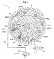
- Fig. 2 is a section view taken along a line II-II in Fig. 1 , as a plane view schematically showing a condition of a phase displacing mechanism under one operational state.
- Numeral 1 in the figures denotes the phase displacing mechanism.
- This phase displacing mechanism 1 includes a drive-side rotational member 12 rotatable in synchronism with an internal combustion engine (“engine”) and a driven-side rotational member 11 arranged coaxially with the drive-side rotational member 12.
- the driven-side rotational member 11 being disposed on the inner side of the drive-side rotational member 12.
- the drive-side rotational member 12 is provided in the exemplary form of a pulley or a sprocket as shown.
- the drive-side rotational member 12 receives rotational force from a crank shaft of the engine via an unillustrated belt or chain.
- the driven-side rotational member 11 is fixed on a cam shaft 10 via a bolt 14 and is rotatable in unison with the drive-side rotational member 12, to rotate the cam shaft 10, thus opening/closing an intake valve and/or an exhaust valve of the engine.
- Each cavity 2 is divided into two kinds of pressure chambers 2A and 2B by means of a vane 13 acting as a movable partition therebetween. While the total capacity of the cavity remains fixed, as the position of the vane 13 is varied within the cavity, respective capacities of the two kinds of pressure chambers 2A and 2B are varied correspondingly in a mutually complimentary manner. And, in association with this change of capacities, the opening/closing timings of the intake valve and/or exhaust valve for the piston-operating engine are changed.
- the partition between the pressure chamber 2A and the pressure chamber 2B is not limited to the vane 13 provided in the form of block shown in Fig. 2 , but can be provided by a plate-like member, instead.
- Fig. 2 shows a condition of an intermediate locking phase that is set as being suitable for start of the internal combustion engine.
- This intermediate locking phase is set within an intermediate region between a most retarding phase where the relative phase of the driven-side rotational member 11 relative to the drive-side rotational member 12 is most retarded and a most advancing phase where the relative phase of the driven-side rotational member 11 relative to the drive-side rotational member is most advanced and fixedly maintained, i.e. locked, by a locking mechanism 6 to be described later.
- valve opening/closing timing control apparatus of the present invention at the time of stopping the engine, the relative phase between the drive-side rotational member 12 and the driven-side rotational member 11 is displaced to this intermediate locking phase and maintained thereto by the locking mechanism 6. Therefore, at this intermediate locking phase condition, the engine can be started in a reliable manner.
- an intermediate restricting phase is set at this intermediate restricting phase.
- this intermediate restricting phase during an idling condition of the engine after its start, improvement of emission performance and torque increase can be achieved, as compared with the intermediate locking phase.
- the phase of the drive-side rotational member 11 is controlled or displaced toward the retarding side relative to the drive-side rotational member 12. Conversely, if the work fluid is fed into the pressure chamber 2B and discharged from the pressure chamber 2A, the phase of the drive-side rotational member 11 is controlled or displaced toward the advancing side relative to the drive-side rotational member 12.
- the pressure chamber 2A will be referred to as an advancing chamber and the pressure chamber 2B will be referred to as a retarding chamber, respectively.
- a passage 21 communicating to the retarding chamber 2A will be referred to as a retarding passage and a passage 22 communicating to the advancing chamber 2B will be referred to as an advancing passage, respectively.
- the retarding chamber 2A and the advancing chamber 2B are not completely sealed, so that if an amount of work oil exceeding the respective capacity thereof is fed thereto, the excess amount of fluid will leak to the outside of the phase displacing mechanism 1.
- An example of the work fluid is engine oil and this leaking excess work fluid or engine oil will be recovered together with an amount of work fluid (engine oil) fed to the respective parts of the engine.
- a torsion spring 3 as an "urging mechanism” for urging the phase displacing mechanism 1 in the direction toward the intermediate locking phase.
- This torsion spring 3 provides an urging force (phase displacement assisting torque) for urging the driven-side rotational member 11 in the advancing direction relative to the drive-side rotational member 12.
- the drive-side rotational member 11 tends to lag, in its displacement, relative to the drive-side rotational member 12, due to resistance received from a valve spring of the intake valve or exhaust valve and/or from the phase displacing mechanism 1.
- the torsion spring 3 acts to restrict this lag, i.e.
- displacement of the phase toward the retarding side more particularly, displacement of the phase toward the retarding side, in a region between the intermediate restricting phase and the most retarding phase and provides also a stopper function in the course of displacement from the intermediate locking phase to the intermediate restricting phase after start of the engine.
- a hydraulic circuit 7 includes a first pump 71 driven by the engine for effecting feeding of oil (this also is engine oil) as the work fluid, a second pump 72, and a work oil reservoir 73 disposed between the first pump 71 and the second pump 72 and capable of reserving an amount of the work oil.
- the second pump 72 is disposed on the downstream of the first pump 71 and is driven by a power source separate from the engine for effecting feeding of the work oil.
- the hydraulic circuit 7 further includes a first control valve 74 for controlling feeding of the work oil to the pressure chambers 2, and a second control valve 75 for controlling feeding of the work oil to the locking mechanism 6.
- This hydraulic circuit 7 still further includes a control unit (ECU) 8 as a controlling means for controlling operations of the second pump 72, the first control valve 74 and the second control valve 75.
- ECU control unit
- the control unit 8 receives signals from a sensor for detecting a crank angle and a sensor for detecting an angular (rotational) phase of a cam shaft. Based upon detection results of these sensors, the control unit 8 calculates a relative phase between the driven-side rotational member 11 and the drive-side rotational member 12 and calculates also a difference, if any, between the calculated relative phase and the intermediate locking phase together with a direction of this displacement (the advancing phase direction or retarding phase direction). And, the control unit 8 operates in such a manner that at the time of stopping engine, the relative phase between the drive-side rotational member 12 and the driven-side rotational member 11 may be displaced to the intermediate locking phase and then locked at this phase by the locking mechanism 6.
- control unit 8 stores, within its memory, optimum relative phases according respectively to various operational states of the engine, so that in accordance with each particular operational state (e.g. rotational speed of the engine, temperature of cooling water) separately detected, an optimum relative phase therefor may be obtained. Therefore, this control unit 8 operates also to render the relative phase optimum for any particular operational state of the engine at that moment. Moreover, this control unit 8 further receives e.g. ON/OFF information of an ignition key, information from an oil leak sensor for detecting leak of the engine oil, etc.
- the first pump 71 is a mechanically driven hydraulic pump driven as receiving the drive force of the crank shaft of the engine. In operation, this first pump 71 draws the work oil reserved in an oil pan 76 via an inlet port and discharges this work oil to the downstream side via a discharge port. This discharge port of the first pump 71 is communicated via a filter 77 to an engine lubricant section 78 and a work oil reservoir 73. In this, it is noted that the engine lubricant section 78 includes all parts or components required for feeding of the work oil to the engine and its peripherals.
- the second pump 72 is constructed as an electrically driven pump driven by a power source different from the engine, in this case, the different power source being an electric motor in particular. With this arrangement, the second pump 72 is rendered operable according to operation signals from the control unit 8, irrespectively or independently of whatever operational state of the engine. In operation, this second pump 72 draws the work oil reserved in the work oil reservoir 73 through its inlet port and discharges this work oil to the downstream side through its discharge port. This discharge port of the second pump 72 is communicated to the first control valve 74 and the second control valve 75.
- the hydraulic circuit 7 includes a bypass passage 79 in parallel with the second pump 72, the bypass passage 79 being configured for establishing communication between the passage on the upstream side of the second pump and the passage on the downstream side of the same.
- This bypass passage 79 incorporates therein a check valve 79a.
- the work oil reservoir 73 is disposed between the first pump 71 and the second pump 72 and includes a reservoir chamber 73a capable of reserving a fixed amount of work oil.
- This work oil reservoir 73 further includes a first communication port 73a for communicating the reservoir chamber 73a to the passage downstream of the first pump 71, a second communication port 73b provided at a lower position than the first communication port 73a and configured for communicating the reservoir chamber 73a to the passage upstream of the second pump 72, and a lubricant communication port 73d provided at a higher position than the first communication port 73b and configured for communicating the reservoir chamber 73a to the engine lubricant section 78.
- the capacity of the reservoir chamber 73a of the work oil reservoir 73 is set such that the capacity portion of its area that is lower than the first communication port 73b and higher than the second communication port 73c may be equal to or greater than the amount (volume) of work oil needed to be fed by the second pump 72 under stopped state of the first pump 71.
- the second pump 72 Under the stopped state of the engine, namely, under the stopped condition of the first pump 71 driven thereby, the second pump 72 effects feeding operation for feeding the work oil to a fluid pressure chamber 4 and the locking mechanism 6. Accordingly, the capacity of the reservoir chamber 73a of the work oil reservoir 73 is set to be equal to or greater than an added-up capacity of the capacities of the fluid pressure chamber 4 and an engaging recess 51 of the locking mechanism 5 and the capacities of the pipes or the like extending from these components to the second pump 72. With this arrangement, under the stopped condition of the first pump 71, the second pump 72, instead, can effect the displacement of the relative phase between the drive-side rotational member 12 and the driven-side rotational member 11 to a target relative phase.
- first control valve 74 it is possible to employ e.g. a variable electromagnetic spool valve configured to displace a spool slidably disposed within a sleeve, against a spring, in response to power supply to a solenoid from the control unit 8.
- This first control valve 74 includes an advancing port communicated to the advancing passage 22, a retarding port communicated to the retarding passage 21, a feeding port communicated to the passage downstream of the second pump 72, and a drain port communicated to the oil pan 76.
- this first control valve 74 is configured as a three-position control valve capable of effecting three modes of control, namely, an advancing control in which communications are established between the advancing port to the feeding port, and between the retarding port and the drain port, a retarding control in which communications are established between the retarding port an the feeding port and between the advancing port and the drain port, and a hold control in which the advancing port and the retarding port are closed. And, the first control valve 74 executes the advancing control or the retarding control under the operational control by the control unit 8.
- This second control valve 75 it is possible to employ a variable electromagnetic spool valve, like the first control valve 74.
- This second control valve 75 includes a lock port communicated to a locking passage 63 as the work oil passage of the locking mechanism 6, a feeding port communicated to the passage downstream of the second pump 72, and a drain port communicated to the oil pan 76.
- this second control valve 75 is configured as a two-position control valve capable of executing two modes of control, namely, a lock releasing control in which communication is established between the locking port and the feeding port and a locking control in which communication is established between the restricting port and the drain port.
- the second control valve 75 effects control of the locking mechanism 6 under the operational control of the control unit 8.
- the locking passage 63 interconnecting between this second control valve 75 and the locking mechanism 6 is independent of the passages interconnecting between the advancing passage 22 or the retarding passage 21 formed inside the phase displacing mechanism 1 to the first control valve 75. So, the control operations for feeding/discharging work oil to/from the locking mechanism 6 can be done, independently of the control operations for feeding/discharging work oil to/from the retarding chamber 2A or the advancing chamber 2B.
- the torsion spring 3 as shown in Figs. 1 and 3 , has its one end 3a fixed to the drive-side rotational member 12 and its other end 3b that can come into contact with a contact face 15a which is a lateral face along the axial direction of a radial opening 15 provided in the driven-side rotational member 11. Further, the leading end of the end 3b is inserted in a spring receiving recess 16 defined in the drive-side rotational member 12 and extending along the radial direction.
- Figs. 3 through 6 show transitions of the relative phase between the drive-side rotational member 12 and the driven-side rotational member 11.
- Fig. 3 shows the most retarding phase state
- Fig. 4 shows an intermediate restricting phase state
- Fig. 5 shows the intermediate locking phase state
- Fig. 6 shows a most advancing phase state, respectively. That is to say, in association with clockwise rotation of the driven-side rotational member 11 relative to the drive-side rotational member 12, there occurs transition from the most retarding phase, via the intermediate restricting phase and the intermediate locking phase, to the most advancing phase.
- the torsion spring 3 is configured to provide its urging force for urging the driven-side rotational member 11 toward the advancing side, only in the pre-defined limited range from the most retarding phase to the intermediate restricting phase.
- the effective range of the urging force 3 is from the relative phase between the driven-side rotational member 11 and the drive-side rotational member 12 being at the most retarding phase (see Fig. 3 ) to the relative phase being substantially at the intermediate restricting phase (see Fig. 4 ).
- the leading end of the end 3b of the torsion spring 3 comes into contact with the contact face 15a to urge the driven-side rotational member 11 in the advancing direction.
- the torsion spring 3 there is selected a torsion spring having such strong enough spring characteristics that the minimal urging force of this torsion spring 3 in the above-described urging force effective range may exceed the displacing force in the retarding direction provided by the phase displacing mechanism 1 when fed with the work oil at the minimum pressure by the first pump 71 driven by the engine.
- the transition of the relative phase from the most retarding phase to the intermediate restricting phase may proceed speedily, thank to the strong assisting force provided by the torsion spring 3.
- the transition of the relative phase from the advancing phase to the intermediate locking phase and the further transition of the same to the intermediate restricting phase may proceed speedily by the cam reaction force and the hydraulic force of the second pump 72 which is activated when needed, since in these displacement ranges, the urging force of the torsion spring 3 is not effective.
- the hydraulic force of the second pump 72 is utilized as an assisting force.
- the strong spring force of this torsion spring 3 provides a stopper effect at the intermediate restricting phase, in case the relative phase is displaced from the intermediate locking phase to the intermediate restricting phase, the phase retention at the intermediate restricting phase is made easy.
- the locking mechanism 6 for locking the relative phase between the drive-side rotational member 12 and the driven-side rotational member 11 to the intermediate locking phase includes, as shown in Fig. 2 , a retarding locking portion 6A and an advancing locking portion 6B both provided in the drive-side rotational member 12, and a locking recess 12 formed in the drive-side rotational member 11 at a part of its outermost peripheral face.
- the retarding locking portion 6A for restricting phase displacement toward the retarding side and the advancing locking portion 6B for restricting phase displacement toward the advancing side each includes a locking piece 60A, 40B supported on the drive-side rotational member 12 to be slidable in the radial direction and a spring 61 protruding to urge the respective locking piece 60A, 40B in the radially inner direction.
- the locking recess 62 extends along the peripheral direction of the driven-side rotational member 11 and is formed not as a ones-stepped recess receiving the locking piece 60A, 60B, but as a two-stepped recess having a retaining recess 62A for providing the locking function as its original function and a restriction assisting retaining recess 62a having a shallower engaging depth for engagement with the locking piece 60a than the retaining recess 62A.
- the restriction assisting retaining recess 62a extends in the advancing direction from the most advancing side end of the retaining recess 62M and its peripheral length corresponds to the distance between the intermediate restricting phase and the intermediate locking phase. That is to say, as may be apparent from Figs.
- the position where the locking piece 60A comes into contact with the end of the restriction assisting retaining recess 62a constitutes the intermediate restricting phase.
- the bottom faces of the retaining recess 62A, the restriction assisting retaining recess 62a and a second assisting retaining recess 26b extend substantially parallel with the outermost peripheral face of the drive-side rotational member 11.
- the shapes of the locking pieces 60A, 60B can be appropriately selected from such shapes as a plate-like shape, a pin-like shape, and the like.
- the retarding locking portion 6A inhibits displacement of the driven-side rotational member 11 from the intermediate locking phase toward the retarding phase side relative to the drive-side rotational member 12 by engaging the retarding locking piece 60A into the retaining recess 62M. and inhibits also displacement of the driven-side rotational member 11 toward the retarding phase side by bringing the retarding locking piece 60A into engagement with the restriction assisting retaining recess 62a.
- the advancing locking portion 6B inhibits relative rotation of the driven-side rotational member 11 relative to the drive-side rotational member 12 from the intermediate locking phase toward the advancing side by bringing the advancing locking piece 60B into engagement with the locking recess 62.
- the width of the retaining recess 62M that is deeper than the restriction assisting retaining recess 62a is set to be substantially equal to the distance between lateral faces of the retarding locking piece 60A and the advancing locking piece 60B which lateral faces are remote from each other in the peripheral direction of the driven-side rotational member 11. Therefore, as shown in Fig. 2 and Fig. 5 , by simultaneously engaging both the retarding locking piece 60A and the advancing locking piece 60B into the retaining recess 62M, the relative phase between the driven-side rotational member 11 and the drive-side rotational member 12 can be restricted to the intermediate locking phase having substantially zero width, i.e. the so-called locked state.
- the locking recess 62 is communicated to the locking passage 63 formed in the driven-side rotational member 11 and this locking passage 63 is connected to the second control valve 75 of the hydraulic circuit 7.
- the pair of locking pieces 60A and 60B which have been engaged within the locking recess 62 will be retracted toward the drive-side rotational member 12 until the leading ends thereof reach positions slightly radially more outward than the outermost peripheral face of the driven-side rotational member 11. With this, the locked state between the drive-side rotational member 12 and the driven-side rotational member 11 is released, thus allowing displacement of the relative phase.
- valve opening/closing timing control apparatus With the valve opening/closing timing control apparatus described above, based upon result of phase detection indicative of which of the advancing or retarding phase the relative phase between the drive-side rotational member 12 and the driven-side rotational member 11 is located relative to the intermediate locking phase, this relative phase can be returned to and locked at the intermediate locking phase at the time of stopping the engine. As the phase is located at the intermediate locking phase at the time of engine stop, the engine can be re-started reliably at the intermediate locking phase suitable for starting the engine.
- examples of the control operations effected by the valve opening/closing timing control apparatus at the time of engine start and engine stop will be described.
- the phase is locked at the intermediate locking phase at the time of starting the engine. So, before an ON operation of the ignition key, the phase displacing mechanism 1 is under the locked state wherein the phase is restricted as being locked to the intermediate locking phase by the locking mechanism 6. Further, the first control valve 74 is located at its neutral position and the feeding/discharging of the work oil to/from the advancing chamber 2B and the retarding chamber 2A are stopped. Then, when engine start is instructed with an ON operation of the ignition key, a cranking operation by a starter motor is effected. With this, the engine is started and the first pump 71 is rotated to allow feeding of the work oil to the advancing chamber 2B and the retarding chamber 2A (#20).
- control unit 8 operates the first control valve 74 to fill both the retarding chamber 2A and the advancing chamber 2B with the work oil (#21). Simultaneously therewith, the control unit controls the second control valve 75 to discharge the work oil from the locking mechanism 6 (#22). With this discharging of work oil of the locking mechanism 6, at the time of engine start, the locking mechanism 6 is retained to the locked state by the force of the spring 61. Once the engine has started (#23) and enters idling rotation, the process checks whether a stepping-on operation of the accelerator pedal has been effected or not (#24).
- the process further checks whether a predetermined period: (t) has lapsed or not (#25).
- This period: (t) is also a period when emission improvement in the intermediate restricting phase can be expected after engine start. So, this period (t) is selected preferably from 20 seconds to 30 seconds, depending on the water temperature of the engine cooling water. If the predetermined period: (t) has not yet lapsed after the engine start ("NO" branching at #25), the process jumps to step #24 to repeat the foregoing procedure.
- step #24 In case it was found at step #24 that a stepping-on operation of the accelerator pedal was effected ("YES" branching at step #24) or it was found at step #25 that the predetermined period (t) had lapsed after the engine start ("YES" branching at step #25), the second control valve 75 is operated to feed the work oil to the locking mechanism 6 (#26). With this feeding of the work oil to the locking mechanism 6, the locked state of the locking mechanism 6 is released. Upon this release of the locked state, the relative phase is displaced by the cam reaction force to the phase retarding direction and when the phase has reached the intermediate restricting phase, under the effect of the strong resistance from the torsion spring 3, the relative phase is maintained in the proximity of the intermediate restricting phase.
- the process checks whether this has been done or not (#27), if, for some reason, the relative phase is currently off the intermediate restricting phase, the control unit 8 operates the first control valve 24 to effect feeding of the work oil to the advancing chamber 2B and the retarding chamber 2A appropriately, thus adjusting the relative phase to the intermediate restricting phase (#28). Once this intermediate restricting phase is maintained, the starting control is terminated and the process goes on to the normal driving control.
- This stopping control process is initiated upon issuance of request for engine stopping by an OFF operation of the ignition key.
- the engine is under its idling rotation. So, with the OFF operation of the ignition key, its rotational speed begins to decrease toward the stop state.
- the control unit 8 activates the second control valve 75 for discharging the work oil from the locking mechanism 6 and lets the movements of the locking pieces 60A and 60B of the locking mechanism 6 subjected to the force of the spring 61 in this projecting direction (#01).
- the second pump 72 is started (#02). Then, based on signals from the sensor for detecting the crank angle and the sensor for detecting an angular phase of the cam shaft, the control unit 8 obtains a current relative phase ("current relative phase") and executes a control operation corresponding to a difference between this current relative phase and the intermediate locking phase (#03).
- the process executes the advancing control for operating the first control valve 74 to feed the work oil to the advancing chamber 2B and to discharge the work oil from the retarding chamber 2A (#04).
- the force tending to displace the phase toward the intermediate locking phase as the locking position comprises the spring force of the torsion spring 3 and the hydraulic force of the second pump 72 and the fore resistant to this comprises the cam reaction force and viscosity reactive force in case the oil has high viscous load.
- the retarding locking piece 60A which was pressed against the surface of the driven-side rotational member 11 will pass the bottom face of the restriction assisting retaining recess 62a and engage into the retaining recess 62M upon returning to the intermediate locking phase and come into contact with the advancing side end of the retaining recess 62M.
- the retaining control will be executed.
- the first control valve 74 may be set to the neutral position and the second pump too can be stopped at this stage (#05). If the current relative phase is located in the intermediate locking phase region, this is a situation where either the retarding locking piece 60A or the advancing locking piece 60B is engaged within the retaining recess 62M or where both the retarding locking piece 60A and the advancing locking piece 60B are engaged in the retaining recess 62M. In the case of the latter situation where both the retarding locking piece 60A and the advancing locking piece 60B are engaged in the retaining recess 62M, the locking state is completed already.
- the displacement width of the relative displacement is only the length of the retaining recess 62M. Therefore, even if the first control valve 74 and the second control valve 75 are set to the neutral position, the relative phase will be returned to the intermediate locking phase by the spring force of the torsion spring 3 and/or the cam reaction force, so that both the retarding locking piece 60A and the advancing locking piece 60B will be engaged into the retaining recess 62M.
- the process executes a retarding control in which the first control valve 74 is operated to feed work oil to the retarding chamber 2A and to discharge work oil from the advancing chamber 2B (#06).
- a retarding control in which the first control valve 74 is operated to feed work oil to the retarding chamber 2A and to discharge work oil from the advancing chamber 2B (#06).
- the force for displacement toward the intermediate locking phase comprises not only the hydraulic force provided by the second pump 72, but also the cam reaction force or the viscosity reaction force in the case of high oil viscous load, while the spring force of the torsion spring 3 is not involved. Therefore, the relative phase will be returned to the intermediate locking phase speedily.
- the process After execution of one of the controls of the advancing control (#04), the retaining control (#05) and the retarding control (#06) based upon the detection result of the current relative phase, the process first checks whether a period of 1(one) second has lapsed or not (#07). If the one-second period has not lapsed ("NO" branching at #07), the process further checks whether the current relative phase has returned to the intermediate locking phase or not (#08). If it is found that the current relative phase has returned to the intermediate locking phase and the phase is locked thereto ("YES" branching at #08), then, an engine stopping process is executed (#09).
- step #07 if the one-second period has lapsed before the current relative phase returns to the intermediate locking phase ("YES" branching at #07), the process effects an engine stopping operation (#10) and then effects checking of the one-second period lapse (#11). That is, after giving the allowable extension period of one-second ("YES" branching at #11), the process jumps to step #12 to effect the completing process.
- the present invention as embodied as a valve opening/closing timing control apparatus capable of allowing smooth displacement of the relative phase, after engine start at the intermediate locking phase, from this intermediate locking phase to the intermediate restricting phase that is a phase slightly displaced therefrom in the retarding direction, is applicable as a peripheral device for various types of engine.
Landscapes
- Engineering & Computer Science (AREA)
- Mechanical Engineering (AREA)
- General Engineering & Computer Science (AREA)
- Chemical & Material Sciences (AREA)
- Combustion & Propulsion (AREA)
- Valve Device For Special Equipments (AREA)
- Output Control And Ontrol Of Special Type Engine (AREA)
Applications Claiming Priority (2)
| Application Number | Priority Date | Filing Date | Title |
|---|---|---|---|
| JP2007242385A JP5046015B2 (ja) | 2007-09-19 | 2007-09-19 | 弁開閉時期制御装置 |
| PCT/JP2008/066152 WO2009037986A1 (fr) | 2007-09-19 | 2008-09-08 | Dispositif de commande de synchronisation d'ouverture/fermeture de soupape |
Publications (3)
| Publication Number | Publication Date |
|---|---|
| EP2157291A1 true EP2157291A1 (fr) | 2010-02-24 |
| EP2157291A4 EP2157291A4 (fr) | 2011-10-05 |
| EP2157291B1 EP2157291B1 (fr) | 2013-02-27 |
Family
ID=40467806
Family Applications (1)
| Application Number | Title | Priority Date | Filing Date |
|---|---|---|---|
| EP08831906A Not-in-force EP2157291B1 (fr) | 2007-09-19 | 2008-09-08 | Dispositif de commande de synchronisation d'ouverture/fermeture de soupape |
Country Status (5)
| Country | Link |
|---|---|
| US (1) | US8210142B2 (fr) |
| EP (1) | EP2157291B1 (fr) |
| JP (1) | JP5046015B2 (fr) |
| CN (1) | CN101680311B (fr) |
| WO (1) | WO2009037986A1 (fr) |
Cited By (8)
| Publication number | Priority date | Publication date | Assignee | Title |
|---|---|---|---|---|
| EP2233705A1 (fr) * | 2009-03-25 | 2010-09-29 | Aisin Seiki Kabushiki Kaisha | Appareil de commande du réglage de distribution |
| US8418664B2 (en) | 2009-06-17 | 2013-04-16 | Aisin Seiki Kabushiki Kaisha | Variable valve timing control apparatus |
| WO2013064261A1 (fr) * | 2011-11-02 | 2013-05-10 | Schaeffler Technologies AG & Co. KG | Mécanisme de réglage d'arbre à cames équipé d'un dispositif de verrouillage |
| EP2636858A1 (fr) * | 2012-03-08 | 2013-09-11 | Aisin Seiki Kabushiki Kaisha | Appareil de contrôle de distribution variable |
| EP2669481A1 (fr) * | 2012-05-30 | 2013-12-04 | Aisin Seiki Kabushiki Kaisha | Dispositif de déphasage d'ouverture des soupapes |
| EP2708721A1 (fr) * | 2011-05-12 | 2014-03-19 | Toyota Jidosha Kabushiki Kaisha | Appareil de commande de moteur à combustion interne |
| CN105229281A (zh) * | 2013-06-04 | 2016-01-06 | 日产自动车株式会社 | 可变气门正时机构的锁止判定装置及可变气门正时机构的锁止判定方法 |
| EP3109422A3 (fr) * | 2015-06-26 | 2017-01-11 | Hyundai Motor Company | Appareil de commande de rotation de cvvt |
Families Citing this family (25)
| Publication number | Priority date | Publication date | Assignee | Title |
|---|---|---|---|---|
| JP4877523B2 (ja) * | 2007-09-19 | 2012-02-15 | アイシン精機株式会社 | 弁開閉時期制御装置 |
| DE102008011915A1 (de) * | 2008-02-29 | 2009-09-03 | Schaeffler Kg | Nockenwellenversteller mit Verriegelungseinrichtung |
| DE102008032948A1 (de) * | 2008-07-12 | 2010-01-14 | Schaeffler Kg | Vorrichtung zur variablen Einstellung der Steuerzeiten von Gaswechselventilen einer Brennkraftmaschine |
| JP5067720B2 (ja) * | 2009-04-23 | 2012-11-07 | 株式会社デンソー | 内燃機関の可変バルブタイミング制御装置 |
| JP5322809B2 (ja) * | 2009-07-01 | 2013-10-23 | 三菱電機株式会社 | バルブタイミング調整装置 |
| JP5516937B2 (ja) * | 2009-09-28 | 2014-06-11 | アイシン精機株式会社 | 弁開閉時期制御装置 |
| US8701615B2 (en) * | 2010-09-18 | 2014-04-22 | Raymond A. Towne, III | Anti-cogging apparatus and methods for reducing cogging of rotating shaft |
| US8464675B2 (en) * | 2010-11-30 | 2013-06-18 | Delphi Technologies, Inc. | Method for operating an oil control valve |
| US8468989B2 (en) * | 2010-11-30 | 2013-06-25 | Delphi Technologies, Inc. | Method for operating a camshaft phaser |
| WO2012094324A1 (fr) * | 2011-01-04 | 2012-07-12 | Hilite Germany Gmbh | Procédé et appareil de commande du réglage de distribution |
| JP5447436B2 (ja) * | 2011-05-20 | 2014-03-19 | 株式会社デンソー | バルブタイミング調整装置 |
| JP5483119B2 (ja) | 2011-07-07 | 2014-05-07 | アイシン精機株式会社 | 弁開閉時期制御装置及び弁開閉時期制御機構 |
| CN103649498B (zh) | 2011-07-12 | 2016-11-09 | 爱信精机株式会社 | 阀开闭时期调整系统 |
| JP5803363B2 (ja) * | 2011-07-12 | 2015-11-04 | アイシン精機株式会社 | 弁開閉時期調整システム |
| JP5771502B2 (ja) * | 2011-10-18 | 2015-09-02 | 株式会社ミクニ | バルブタイミング変更装置 |
| DE112011100407B4 (de) * | 2011-11-10 | 2014-09-25 | Toyota Jidosha Kabushiki Kaisha | Steuervorrichtung für einen verbrennungsmotor |
| JP5966781B2 (ja) * | 2012-09-06 | 2016-08-10 | アイシン精機株式会社 | 弁開閉時期制御システム |
| JP6075449B2 (ja) * | 2013-05-30 | 2017-02-08 | アイシン精機株式会社 | 弁開閉時期制御装置 |
| US10202911B2 (en) * | 2013-07-10 | 2019-02-12 | Ford Global Technologies, Llc | Method and system for an engine for detection and mitigation of insufficient torque |
| CN107614840B (zh) * | 2015-06-02 | 2019-12-20 | 日立汽车系统株式会社 | 内燃机的气门正时控制装置 |
| JP6352888B2 (ja) * | 2015-11-18 | 2018-07-04 | トヨタ自動車株式会社 | 内燃機関の制御装置 |
| WO2017159121A1 (fr) * | 2016-03-15 | 2017-09-21 | 日立オートモティブシステムズ株式会社 | Dispositif de commande de réglage de distribution pour moteur à combustion interne et procédé de fixation de dispositif de commande de réglage de distribution |
| US10472999B2 (en) * | 2016-08-18 | 2019-11-12 | Ford Global Technologies, Llc | Methods and system for adjusting camshafts |
| CN107091129A (zh) * | 2017-05-31 | 2017-08-25 | 重庆小康工业集团股份有限公司 | 一种发动机可变凸轮轴相位调节器 |
| CN110410168B (zh) * | 2018-04-28 | 2021-07-16 | 联合汽车电子有限公司 | 中间锁止vvt系统的控制系统及控制方法 |
Citations (4)
| Publication number | Priority date | Publication date | Assignee | Title |
|---|---|---|---|---|
| US20030121486A1 (en) * | 2001-12-05 | 2003-07-03 | Osamu Komazawa | Valve timing control device |
| WO2006011648A1 (fr) * | 2004-07-28 | 2006-02-02 | Aisin Seiki Kabushiki Kaisha | Dispositif de commande de réglage de distribution variable |
| EP1672188A1 (fr) * | 2004-12-16 | 2006-06-21 | Aisin Seiki Kabushiki Kaisha | Déphaseur d'arbre à cames et méthode pour déterminer un couple minimal |
| JP2006348926A (ja) * | 2005-05-19 | 2006-12-28 | Aisin Seiki Co Ltd | 弁開閉時期制御装置 |
Family Cites Families (15)
| Publication number | Priority date | Publication date | Assignee | Title |
|---|---|---|---|---|
| JP3211713B2 (ja) | 1996-04-04 | 2001-09-25 | トヨタ自動車株式会社 | 内燃機関の可変バルブタイミング機構 |
| KR100242589B1 (ko) * | 1996-04-04 | 2000-03-02 | 와다 아끼히로 | 내연기관의 가변밸브 타이밍기구 |
| JP4202440B2 (ja) * | 1997-02-06 | 2008-12-24 | アイシン精機株式会社 | 弁開閉時期制御装置 |
| JP4465846B2 (ja) * | 2000-09-27 | 2010-05-26 | アイシン精機株式会社 | 弁開閉時期制御装置 |
| JP4284871B2 (ja) | 2001-01-31 | 2009-06-24 | 株式会社デンソー | 内燃機関用バルブタイミング調整装置 |
| US6439184B1 (en) * | 2001-01-31 | 2002-08-27 | Denso Corporation | Valve timing adjusting system of internal combustion engine |
| JP4329274B2 (ja) | 2001-03-30 | 2009-09-09 | 株式会社デンソー | バルブタイミング調整装置 |
| JP2004060572A (ja) | 2002-07-30 | 2004-02-26 | Aisin Seiki Co Ltd | 内燃機関のバルブタイミング制御装置 |
| JP4214972B2 (ja) * | 2003-08-28 | 2009-01-28 | アイシン精機株式会社 | 弁開閉時期制御装置 |
| DE102004012460B3 (de) * | 2004-03-11 | 2005-10-13 | Hydraulik-Ring Gmbh | Nockenwellenversteller mit konstruktiv frei wählbarer Verriegelungsposition |
| JP2006144766A (ja) * | 2004-10-20 | 2006-06-08 | Aisin Seiki Co Ltd | 弁開閉時期制御装置 |
| JP4320645B2 (ja) * | 2005-05-19 | 2009-08-26 | アイシン精機株式会社 | 弁開閉時期制御装置 |
| JP4534157B2 (ja) * | 2005-11-10 | 2010-09-01 | アイシン精機株式会社 | 弁開閉時期制御装置 |
| GB2437305B (en) | 2006-04-19 | 2011-01-12 | Mechadyne Plc | Hydraulic camshaft phaser with mechanical lock |
| JP4877523B2 (ja) * | 2007-09-19 | 2012-02-15 | アイシン精機株式会社 | 弁開閉時期制御装置 |
-
2007
- 2007-09-19 JP JP2007242385A patent/JP5046015B2/ja not_active Expired - Fee Related
-
2008
- 2008-09-08 CN CN2008800189196A patent/CN101680311B/zh not_active Expired - Fee Related
- 2008-09-08 EP EP08831906A patent/EP2157291B1/fr not_active Not-in-force
- 2008-09-08 US US12/602,605 patent/US8210142B2/en not_active Expired - Fee Related
- 2008-09-08 WO PCT/JP2008/066152 patent/WO2009037986A1/fr active Application Filing
Patent Citations (4)
| Publication number | Priority date | Publication date | Assignee | Title |
|---|---|---|---|---|
| US20030121486A1 (en) * | 2001-12-05 | 2003-07-03 | Osamu Komazawa | Valve timing control device |
| WO2006011648A1 (fr) * | 2004-07-28 | 2006-02-02 | Aisin Seiki Kabushiki Kaisha | Dispositif de commande de réglage de distribution variable |
| EP1672188A1 (fr) * | 2004-12-16 | 2006-06-21 | Aisin Seiki Kabushiki Kaisha | Déphaseur d'arbre à cames et méthode pour déterminer un couple minimal |
| JP2006348926A (ja) * | 2005-05-19 | 2006-12-28 | Aisin Seiki Co Ltd | 弁開閉時期制御装置 |
Non-Patent Citations (1)
| Title |
|---|
| See also references of WO2009037986A1 * |
Cited By (16)
| Publication number | Priority date | Publication date | Assignee | Title |
|---|---|---|---|---|
| US8336510B2 (en) | 2009-03-25 | 2012-12-25 | Aisin Seiki Kabushiki Kaisha | Valve timing control apparatus |
| EP2233705A1 (fr) * | 2009-03-25 | 2010-09-29 | Aisin Seiki Kabushiki Kaisha | Appareil de commande du réglage de distribution |
| US8418664B2 (en) | 2009-06-17 | 2013-04-16 | Aisin Seiki Kabushiki Kaisha | Variable valve timing control apparatus |
| EP2708721A1 (fr) * | 2011-05-12 | 2014-03-19 | Toyota Jidosha Kabushiki Kaisha | Appareil de commande de moteur à combustion interne |
| EP2708721A4 (fr) * | 2011-05-12 | 2014-12-17 | Toyota Motor Co Ltd | Appareil de commande de moteur à combustion interne |
| WO2013064261A1 (fr) * | 2011-11-02 | 2013-05-10 | Schaeffler Technologies AG & Co. KG | Mécanisme de réglage d'arbre à cames équipé d'un dispositif de verrouillage |
| US8776748B2 (en) | 2012-03-08 | 2014-07-15 | Aisin Seiki Kabushiki Kaisha | Variable valve timing control apparatus |
| CN103306769A (zh) * | 2012-03-08 | 2013-09-18 | 爱信精机株式会社 | 可变气门正时控制装置 |
| EP2636858A1 (fr) * | 2012-03-08 | 2013-09-11 | Aisin Seiki Kabushiki Kaisha | Appareil de contrôle de distribution variable |
| CN103306769B (zh) * | 2012-03-08 | 2016-04-06 | 爱信精机株式会社 | 可变气门正时控制装置 |
| EP2669481A1 (fr) * | 2012-05-30 | 2013-12-04 | Aisin Seiki Kabushiki Kaisha | Dispositif de déphasage d'ouverture des soupapes |
| US8794202B2 (en) | 2012-05-30 | 2014-08-05 | Aisin Seiki Kabushiki Kaisha | Valve timing control apparatus |
| CN105229281A (zh) * | 2013-06-04 | 2016-01-06 | 日产自动车株式会社 | 可变气门正时机构的锁止判定装置及可变气门正时机构的锁止判定方法 |
| EP3006696A4 (fr) * | 2013-06-04 | 2016-06-22 | Nissan Motor | Dispositif de détermination de blocage pour un mécanisme de distribution variable, et procédé de détermination de blocage pour un mécanisme de distribution variable |
| US9885259B2 (en) | 2013-06-04 | 2018-02-06 | Nissan Motor Co., Ltd. | Lock determination device for variable valve timing mechanism and lock determination method for variable valve timing mechanism |
| EP3109422A3 (fr) * | 2015-06-26 | 2017-01-11 | Hyundai Motor Company | Appareil de commande de rotation de cvvt |
Also Published As
| Publication number | Publication date |
|---|---|
| CN101680311A (zh) | 2010-03-24 |
| JP5046015B2 (ja) | 2012-10-10 |
| CN101680311B (zh) | 2012-07-18 |
| US20100175649A1 (en) | 2010-07-15 |
| JP2009074384A (ja) | 2009-04-09 |
| WO2009037986A1 (fr) | 2009-03-26 |
| EP2157291A4 (fr) | 2011-10-05 |
| EP2157291B1 (fr) | 2013-02-27 |
| US8210142B2 (en) | 2012-07-03 |
Similar Documents
| Publication | Publication Date | Title |
|---|---|---|
| EP2157291B1 (fr) | Dispositif de commande de synchronisation d'ouverture/fermeture de soupape | |
| US8267058B2 (en) | Valve opening/closing timing control apparatus | |
| JP4687964B2 (ja) | 弁開閉時期制御装置 | |
| EP2372118B1 (fr) | Appareil de commande du réglage de distribution | |
| JP5516938B2 (ja) | 弁開閉時期制御装置 | |
| US20100269772A1 (en) | Variable valve timing control apparatus for internal combustion engine | |
| JP5739305B2 (ja) | 内燃機関のバルブタイミング制御装置 | |
| CN102828794B (zh) | 内燃机的气门正时控制装置 | |
| EP2863024B1 (fr) | Unité de commande de réglage de distribution | |
| EP2743479B1 (fr) | Dispositif de commande du calage des soupapes d'un moteur | |
| CN102200042B (zh) | 机油压力控制装置 | |
| EP2481896A1 (fr) | Dispositif synchronisateur d'ouverture/fermeture de soupapes | |
| EP2669481B1 (fr) | Dispositif de déphasage d'ouverture des soupapes | |
| JP6075449B2 (ja) | 弁開閉時期制御装置 | |
| JP4531705B2 (ja) | 弁開閉時期制御装置 | |
| EP3029286B1 (fr) | Dispositif de commande de synchronisation d'ouverture/fermeture de soupape | |
| WO2015019735A1 (fr) | Dispositif de commande du calage d'ouverture/fermeture de soupapes | |
| JP5482566B2 (ja) | バルブタイミング調整装置 | |
| JP2004340019A (ja) | 車載内燃機関のバルブタイミング制御装置 |
Legal Events
| Date | Code | Title | Description |
|---|---|---|---|
| PUAI | Public reference made under article 153(3) epc to a published international application that has entered the european phase |
Free format text: ORIGINAL CODE: 0009012 |
|
| 17P | Request for examination filed |
Effective date: 20091201 |
|
| AK | Designated contracting states |
Kind code of ref document: A1 Designated state(s): AT BE BG CH CY CZ DE DK EE ES FI FR GB GR HR HU IE IS IT LI LT LU LV MC MT NL NO PL PT RO SE SI SK TR |
|
| AX | Request for extension of the european patent |
Extension state: AL BA MK RS |
|
| DAX | Request for extension of the european patent (deleted) | ||
| A4 | Supplementary search report drawn up and despatched |
Effective date: 20110907 |
|
| RIC1 | Information provided on ipc code assigned before grant |
Ipc: F01L 1/344 20060101ALI20110901BHEP Ipc: F01L 1/34 20060101AFI20110901BHEP Ipc: F02D 13/02 20060101ALI20110901BHEP |
|
| RIC1 | Information provided on ipc code assigned before grant |
Ipc: F01L 1/344 20060101ALI20120508BHEP Ipc: F01L 1/02 20060101ALI20120508BHEP Ipc: F02D 13/02 20060101ALI20120508BHEP Ipc: F01L 1/34 20060101AFI20120508BHEP |
|
| GRAP | Despatch of communication of intention to grant a patent |
Free format text: ORIGINAL CODE: EPIDOSNIGR1 |
|
| GRAS | Grant fee paid |
Free format text: ORIGINAL CODE: EPIDOSNIGR3 |
|
| GRAA | (expected) grant |
Free format text: ORIGINAL CODE: 0009210 |
|
| AK | Designated contracting states |
Kind code of ref document: B1 Designated state(s): AT BE BG CH CY CZ DE DK EE ES FI FR GB GR HR HU IE IS IT LI LT LU LV MC MT NL NO PL PT RO SE SI SK TR |
|
| REG | Reference to a national code |
Ref country code: GB Ref legal event code: FG4D |
|
| REG | Reference to a national code |
Ref country code: CH Ref legal event code: EP |
|
| REG | Reference to a national code |
Ref country code: AT Ref legal event code: REF Ref document number: 598647 Country of ref document: AT Kind code of ref document: T Effective date: 20130315 |
|
| REG | Reference to a national code |
Ref country code: IE Ref legal event code: FG4D |
|
| REG | Reference to a national code |
Ref country code: DE Ref legal event code: R096 Ref document number: 602008022575 Country of ref document: DE Effective date: 20130425 |
|
| REG | Reference to a national code |
Ref country code: AT Ref legal event code: MK05 Ref document number: 598647 Country of ref document: AT Kind code of ref document: T Effective date: 20130227 |
|
| REG | Reference to a national code |
Ref country code: LT Ref legal event code: MG4D |
|
| PG25 | Lapsed in a contracting state [announced via postgrant information from national office to epo] |
Ref country code: LT Free format text: LAPSE BECAUSE OF FAILURE TO SUBMIT A TRANSLATION OF THE DESCRIPTION OR TO PAY THE FEE WITHIN THE PRESCRIBED TIME-LIMIT Effective date: 20130227 Ref country code: ES Free format text: LAPSE BECAUSE OF FAILURE TO SUBMIT A TRANSLATION OF THE DESCRIPTION OR TO PAY THE FEE WITHIN THE PRESCRIBED TIME-LIMIT Effective date: 20130607 Ref country code: BG Free format text: LAPSE BECAUSE OF FAILURE TO SUBMIT A TRANSLATION OF THE DESCRIPTION OR TO PAY THE FEE WITHIN THE PRESCRIBED TIME-LIMIT Effective date: 20130527 Ref country code: SE Free format text: LAPSE BECAUSE OF FAILURE TO SUBMIT A TRANSLATION OF THE DESCRIPTION OR TO PAY THE FEE WITHIN THE PRESCRIBED TIME-LIMIT Effective date: 20130227 Ref country code: IS Free format text: LAPSE BECAUSE OF FAILURE TO SUBMIT A TRANSLATION OF THE DESCRIPTION OR TO PAY THE FEE WITHIN THE PRESCRIBED TIME-LIMIT Effective date: 20130627 Ref country code: AT Free format text: LAPSE BECAUSE OF FAILURE TO SUBMIT A TRANSLATION OF THE DESCRIPTION OR TO PAY THE FEE WITHIN THE PRESCRIBED TIME-LIMIT Effective date: 20130227 Ref country code: NO Free format text: LAPSE BECAUSE OF FAILURE TO SUBMIT A TRANSLATION OF THE DESCRIPTION OR TO PAY THE FEE WITHIN THE PRESCRIBED TIME-LIMIT Effective date: 20130527 |
|
| REG | Reference to a national code |
Ref country code: NL Ref legal event code: VDEP Effective date: 20130227 |
|
| PG25 | Lapsed in a contracting state [announced via postgrant information from national office to epo] |
Ref country code: LV Free format text: LAPSE BECAUSE OF FAILURE TO SUBMIT A TRANSLATION OF THE DESCRIPTION OR TO PAY THE FEE WITHIN THE PRESCRIBED TIME-LIMIT Effective date: 20130227 Ref country code: BE Free format text: LAPSE BECAUSE OF FAILURE TO SUBMIT A TRANSLATION OF THE DESCRIPTION OR TO PAY THE FEE WITHIN THE PRESCRIBED TIME-LIMIT Effective date: 20130227 Ref country code: SI Free format text: LAPSE BECAUSE OF FAILURE TO SUBMIT A TRANSLATION OF THE DESCRIPTION OR TO PAY THE FEE WITHIN THE PRESCRIBED TIME-LIMIT Effective date: 20130227 Ref country code: PT Free format text: LAPSE BECAUSE OF FAILURE TO SUBMIT A TRANSLATION OF THE DESCRIPTION OR TO PAY THE FEE WITHIN THE PRESCRIBED TIME-LIMIT Effective date: 20130627 Ref country code: PL Free format text: LAPSE BECAUSE OF FAILURE TO SUBMIT A TRANSLATION OF THE DESCRIPTION OR TO PAY THE FEE WITHIN THE PRESCRIBED TIME-LIMIT Effective date: 20130227 Ref country code: GR Free format text: LAPSE BECAUSE OF FAILURE TO SUBMIT A TRANSLATION OF THE DESCRIPTION OR TO PAY THE FEE WITHIN THE PRESCRIBED TIME-LIMIT Effective date: 20130528 Ref country code: FI Free format text: LAPSE BECAUSE OF FAILURE TO SUBMIT A TRANSLATION OF THE DESCRIPTION OR TO PAY THE FEE WITHIN THE PRESCRIBED TIME-LIMIT Effective date: 20130227 |
|
| PG25 | Lapsed in a contracting state [announced via postgrant information from national office to epo] |
Ref country code: HR Free format text: LAPSE BECAUSE OF FAILURE TO SUBMIT A TRANSLATION OF THE DESCRIPTION OR TO PAY THE FEE WITHIN THE PRESCRIBED TIME-LIMIT Effective date: 20130227 |
|
| PG25 | Lapsed in a contracting state [announced via postgrant information from national office to epo] |
Ref country code: EE Free format text: LAPSE BECAUSE OF FAILURE TO SUBMIT A TRANSLATION OF THE DESCRIPTION OR TO PAY THE FEE WITHIN THE PRESCRIBED TIME-LIMIT Effective date: 20130227 Ref country code: DK Free format text: LAPSE BECAUSE OF FAILURE TO SUBMIT A TRANSLATION OF THE DESCRIPTION OR TO PAY THE FEE WITHIN THE PRESCRIBED TIME-LIMIT Effective date: 20130227 Ref country code: NL Free format text: LAPSE BECAUSE OF FAILURE TO SUBMIT A TRANSLATION OF THE DESCRIPTION OR TO PAY THE FEE WITHIN THE PRESCRIBED TIME-LIMIT Effective date: 20130227 Ref country code: CZ Free format text: LAPSE BECAUSE OF FAILURE TO SUBMIT A TRANSLATION OF THE DESCRIPTION OR TO PAY THE FEE WITHIN THE PRESCRIBED TIME-LIMIT Effective date: 20130227 Ref country code: SK Free format text: LAPSE BECAUSE OF FAILURE TO SUBMIT A TRANSLATION OF THE DESCRIPTION OR TO PAY THE FEE WITHIN THE PRESCRIBED TIME-LIMIT Effective date: 20130227 Ref country code: RO Free format text: LAPSE BECAUSE OF FAILURE TO SUBMIT A TRANSLATION OF THE DESCRIPTION OR TO PAY THE FEE WITHIN THE PRESCRIBED TIME-LIMIT Effective date: 20130227 |
|
| PG25 | Lapsed in a contracting state [announced via postgrant information from national office to epo] |
Ref country code: CY Free format text: LAPSE BECAUSE OF FAILURE TO SUBMIT A TRANSLATION OF THE DESCRIPTION OR TO PAY THE FEE WITHIN THE PRESCRIBED TIME-LIMIT Effective date: 20130227 |
|
| PG25 | Lapsed in a contracting state [announced via postgrant information from national office to epo] |
Ref country code: IT Free format text: LAPSE BECAUSE OF FAILURE TO SUBMIT A TRANSLATION OF THE DESCRIPTION OR TO PAY THE FEE WITHIN THE PRESCRIBED TIME-LIMIT Effective date: 20130227 |
|
| PLBE | No opposition filed within time limit |
Free format text: ORIGINAL CODE: 0009261 |
|
| STAA | Information on the status of an ep patent application or granted ep patent |
Free format text: STATUS: NO OPPOSITION FILED WITHIN TIME LIMIT |
|
| 26N | No opposition filed |
Effective date: 20131128 |
|
| REG | Reference to a national code |
Ref country code: DE Ref legal event code: R097 Ref document number: 602008022575 Country of ref document: DE Effective date: 20131128 |
|
| PG25 | Lapsed in a contracting state [announced via postgrant information from national office to epo] |
Ref country code: MC Free format text: LAPSE BECAUSE OF FAILURE TO SUBMIT A TRANSLATION OF THE DESCRIPTION OR TO PAY THE FEE WITHIN THE PRESCRIBED TIME-LIMIT Effective date: 20130227 |
|
| REG | Reference to a national code |
Ref country code: CH Ref legal event code: PL |
|
| GBPC | Gb: european patent ceased through non-payment of renewal fee |
Effective date: 20130908 |
|
| REG | Reference to a national code |
Ref country code: IE Ref legal event code: MM4A |
|
| PG25 | Lapsed in a contracting state [announced via postgrant information from national office to epo] |
Ref country code: LI Free format text: LAPSE BECAUSE OF NON-PAYMENT OF DUE FEES Effective date: 20130930 Ref country code: GB Free format text: LAPSE BECAUSE OF NON-PAYMENT OF DUE FEES Effective date: 20130908 Ref country code: IE Free format text: LAPSE BECAUSE OF NON-PAYMENT OF DUE FEES Effective date: 20130908 Ref country code: CH Free format text: LAPSE BECAUSE OF NON-PAYMENT OF DUE FEES Effective date: 20130930 |
|
| PG25 | Lapsed in a contracting state [announced via postgrant information from national office to epo] |
Ref country code: MT Free format text: LAPSE BECAUSE OF FAILURE TO SUBMIT A TRANSLATION OF THE DESCRIPTION OR TO PAY THE FEE WITHIN THE PRESCRIBED TIME-LIMIT Effective date: 20130227 Ref country code: TR Free format text: LAPSE BECAUSE OF FAILURE TO SUBMIT A TRANSLATION OF THE DESCRIPTION OR TO PAY THE FEE WITHIN THE PRESCRIBED TIME-LIMIT Effective date: 20130227 |
|
| PG25 | Lapsed in a contracting state [announced via postgrant information from national office to epo] |
Ref country code: HU Free format text: LAPSE BECAUSE OF FAILURE TO SUBMIT A TRANSLATION OF THE DESCRIPTION OR TO PAY THE FEE WITHIN THE PRESCRIBED TIME-LIMIT; INVALID AB INITIO Effective date: 20080908 Ref country code: LU Free format text: LAPSE BECAUSE OF NON-PAYMENT OF DUE FEES Effective date: 20130908 |
|
| REG | Reference to a national code |
Ref country code: FR Ref legal event code: PLFP Year of fee payment: 9 |
|
| REG | Reference to a national code |
Ref country code: FR Ref legal event code: PLFP Year of fee payment: 10 |
|
| REG | Reference to a national code |
Ref country code: DE Ref legal event code: R084 Ref document number: 602008022575 Country of ref document: DE |
|
| REG | Reference to a national code |
Ref country code: FR Ref legal event code: PLFP Year of fee payment: 11 |
|
| PGFP | Annual fee paid to national office [announced via postgrant information from national office to epo] |
Ref country code: DE Payment date: 20190827 Year of fee payment: 12 Ref country code: FR Payment date: 20190815 Year of fee payment: 12 |
|
| REG | Reference to a national code |
Ref country code: DE Ref legal event code: R119 Ref document number: 602008022575 Country of ref document: DE |
|
| PG25 | Lapsed in a contracting state [announced via postgrant information from national office to epo] |
Ref country code: DE Free format text: LAPSE BECAUSE OF NON-PAYMENT OF DUE FEES Effective date: 20210401 Ref country code: FR Free format text: LAPSE BECAUSE OF NON-PAYMENT OF DUE FEES Effective date: 20200930 |