EP2156040B1 - Einteilig gegossenes kurbelgehäuse für einen mehrzylindermotor - Google Patents
Einteilig gegossenes kurbelgehäuse für einen mehrzylindermotor Download PDFInfo
- Publication number
- EP2156040B1 EP2156040B1 EP08759282.0A EP08759282A EP2156040B1 EP 2156040 B1 EP2156040 B1 EP 2156040B1 EP 08759282 A EP08759282 A EP 08759282A EP 2156040 B1 EP2156040 B1 EP 2156040B1
- Authority
- EP
- European Patent Office
- Prior art keywords
- crankcase
- crankshaft
- bore
- engine
- housing
- Prior art date
- Legal status (The legal status is an assumption and is not a legal conclusion. Google has not performed a legal analysis and makes no representation as to the accuracy of the status listed.)
- Active
Links
Images



Classifications
-
- F—MECHANICAL ENGINEERING; LIGHTING; HEATING; WEAPONS; BLASTING
- F02—COMBUSTION ENGINES; HOT-GAS OR COMBUSTION-PRODUCT ENGINE PLANTS
- F02F—CYLINDERS, PISTONS OR CASINGS, FOR COMBUSTION ENGINES; ARRANGEMENTS OF SEALINGS IN COMBUSTION ENGINES
- F02F7/00—Casings, e.g. crankcases
- F02F7/0043—Arrangements of mechanical drive elements
- F02F7/0046—Shape of casings adapted to facilitate fitting or dismantling of engine parts
-
- F—MECHANICAL ENGINEERING; LIGHTING; HEATING; WEAPONS; BLASTING
- F16—ENGINEERING ELEMENTS AND UNITS; GENERAL MEASURES FOR PRODUCING AND MAINTAINING EFFECTIVE FUNCTIONING OF MACHINES OR INSTALLATIONS; THERMAL INSULATION IN GENERAL
- F16M—FRAMES, CASINGS OR BEDS OF ENGINES, MACHINES OR APPARATUS, NOT SPECIFIC TO ENGINES, MACHINES OR APPARATUS PROVIDED FOR ELSEWHERE; STANDS; SUPPORTS
- F16M1/00—Frames or casings of engines, machines or apparatus; Frames serving as machinery beds
- F16M1/02—Frames or casings of engines, machines or apparatus; Frames serving as machinery beds for reciprocating engines or similar machines
- F16M1/021—Frames or casings of engines, machines or apparatus; Frames serving as machinery beds for reciprocating engines or similar machines for housing crankshafts
Definitions
- the present invention relates to a one-piece cast crankcase for a multi-cylinder engine, in particular a multi-cylinder diesel engine, according to the preamble of claim 1.
- crankcases are widely used in the art.
- the crankshaft to be inserted into the crankcase is usually inserted in a horizontal position from below into the crankcase open on the underside and equipped on the so-called flywheel side of the crankcase with one of its shaft ends with a flywheel reducing the torsional vibrations of the crankshaft.
- the flywheel side opposite side of the crankcase is referred to as the control side and usually has an open contour or large openings or openings.
- To the cover a separate, to be attached to the crankcase control cover is provided in the prior art. Below the crankcase and from the side adjoining the control cover usually an oil pan for receiving the oil sump is attached, including appropriate flange for attaching and sealing the oil pan are provided on the underside of the crankcase and control cover.
- crankcase is also a fully continuous, provided in a plane extending flange for connecting the oil pan.
- the assembly of the crankshaft takes place here by introducing the same through a wall opening in the side opposite the control side of the engine crankcase.
- the height of the crankcase is to be determined by the size of this wall opening through which the complete crankshaft fits through.
- Both ends of the crankshaft are mounted in bearing bushes of opposite cover parts which sealingly close such wall openings in both side walls of the crankcase.
- crankcase according to the invention is completely closed on its control side to a single bore, can be dispensed with a separate control housing, which brings a significant cost savings.
- One anyway type of seal between a control housing and the crankcase is not required.
- the sealing of the bore provided for carrying out the crankshaft in the crankcase according to the invention realized in such a way that the crankcase outside the bore fully enclosing sealing surface provides, against a corresponding sealing surface of the housing of an engine block to be attached to the crankcase, in particular the pump housing of the crankshaft driven oil pump tight.
- crankshaft In principle, a divisible in its longitudinal axis crankshaft could be used, which would be easily used by the opening formed by the flange on the underside of the crankcase in two parts to be joined later.
- the invention proposes for stability reasons, the use of a one-piece crankshaft, wherein the control side provided for carrying out the control shaft end of the crankshaft bore in the crankcase in its diameter or its shape is dimensioned such that the crankshaft in an inclined position in the bore on or can be passed with its shaft end.
- the crankshaft is to bring for assembly purposes in an inclined position, because the inside diameter of the opening formed by the flange on the underside of the crankcase is not sufficient to pass the crankshaft in a horizontal orientation vertically through this opening.
- the one-piece cast crankcase also forms the housing of an exhaust gas recirculation cooler, which further required in the prior art seals to an otherwise separately produced and to be mounted housing of a commercial EGR cooler can be avoided.
- the required connection of the exhaust gas recirculation cooler to the coolant circuit of the engine can be done by fully integrated into the one-piece molded crankcase water channels.
- the - depending on the engine design - to be cooled partial flow of the entire exhaust gas can be performed in a simple manner in a stainless steel tube, which is connected to the exhaust gas outlet of the engine through which the housing of the EGR cooler forming crankcase is guided while being surrounded by cooling water.
- the present invention relates not only to a crankcase of the type described above but also to a multi-cylinder (diesel) engine having a crankcase of the type described above.
- the invention will be explained in more detail with reference to the embodiment shown in the drawing.
- crankcase 1 shown below is cast in one piece and intended for a 4-cylinder diesel engine.
- the crankcase 1 comprises a receptacle 2 for a along the axis A horizontally extending crankshaft (not shown) and a total of four cylinder bores 3.
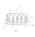
- the crankcase is designed with a fully encircling, unbroken flange 5 for mounting an oil pan, so that the - in the Fig.
- the sealing line 6 extends together with the flange 5 in an exactly horizontal plane.
- the crankcase 1 On the control side 7, the crankcase 1 is completely closed with the exception of one end of the crankshaft receiving bore 8, so that can be dispensed with a separate control housing.
- the bore 8 is completely surrounded by a sealing surface 9 of the crankcase 1, with which, when the engine is mounted, a sealing surface of the housing of an oil pump driven by the control end of the crankshaft (in FIGS Fig. 1 to 3 not shown) sealingly cooperates.
- the flywheel side 10 of the crankcase 1 opposite the control side 7 serves as the main output side of a diesel engine equipped with the crankcase 1 according to the invention.
- the provided for the crankshaft 1 receptacle 2 therefore borders flywheel side to corresponding receptacles 11, 12 for the flywheel and the output gear (both not shown).
- the bore 8 on the control side 7 of the crankcase 1 has a larger diameter than the crankshaft, so that the crankshaft in oblique position along the in Fig. 2 represented axis B with its control-side shaft end - through the opening formed by the flange 6 on the underside of the crankcase 1 - introduced into the bore 8 and then - contactless in its horizontal position within the storage chairs 13 according to axis A can be pivoted. Subsequently, a suitable bearing ring is installed between the crankshaft and bore 8.
- crankshaft and its receptacle 2 within the bearing blocks 13 and the flywheel and the output-side gear and the receptacles provided for this purpose 11, 12 are dimensioned so that the necessary for installation and removal of the crankshaft pivotal movement is feasible.
- the housing 14 of an exhaust gas recirculation cooler cast integrally with the crankcase 1 is laterally provided on the crankcase 1 into which a stainless steel tube (not shown) is introduced parallel to the crankshaft axis A as an exhaust gas recirculation passage through a bore 15 to be provided on the flywheel side, which is then inserted within the housing 14 is flowed around by cooling water.
- Fig. 4 finally shows a partially assembled 3-cylinder diesel engine 16 in a perspective view, which is equipped with a crankcase 1 'according to the invention. Since the crankcase 1 'with the exception of the number of cylinders in the features essential to the invention with the crankcase 1 from the Fig. 1 to 3 over-coincides, in this regard to the extent also valid statements in connection with the embodiment of the crankcase 1 according to the invention Fig. 1 to 3 directed.
- crankcase 1 ' On the underside of the crankcase 1 'is in the diesel engine 16 off Fig. 4 an oil pan 17 is attached, which is sealed against a completely encircling, uninterrupted and extending in a horizontal plane flange 5 'of the crankcase 1'.
- oil pump 18 On the control side of the diesel engine 16 is in the range of - not visible here - bore for the crankshaft operated by the crankshaft oil pump 18 is attached, which is sealed at its housing with a circumferential sealing surface against a bore surrounding the sealing surface of the crankcase 1 '.
- the oil filter 19 is also installed on the control side.
- a cylinder head 26 At the top of the crankcase, a cylinder head 26 is screwed, the valve gear is closed by a cylinder head cover 20.
- the exhaust tap line 22 is connected to a steel pipe extending within the housing 14 'of the exhaust gas recirculation cooler.
- the cooling water for the exhaust gas recirculation cooler flows immediately after emerging from the control side of the crankshaft housing 1 'flanged water pump 23 in the housing 14'. Further, on the crankcase 1 ', a starter 24 and a usual industrial diesel engines connection housing 25 are mounted.
Landscapes
- Engineering & Computer Science (AREA)
- General Engineering & Computer Science (AREA)
- Mechanical Engineering (AREA)
- Chemical & Material Sciences (AREA)
- Combustion & Propulsion (AREA)
- Cylinder Crankcases Of Internal Combustion Engines (AREA)
- Lubrication Details And Ventilation Of Internal Combustion Engines (AREA)
Description
- Die vorliegende Erfindung betrifft ein einteilig gegossenes Kurbelgehäuse für einen Mehrzylindermotor, insbesondere einen Mehrzylinder-Dieselmotor, nach dem Oberbegriff von Anspruch 1.
- Derartige Kurbelgehäuse sind im Stand der Technik weit verbreitet. Die in das Kurbelgehäuse einzusetzende Kurbelwelle wird üblicherweise in horizontaler Lage von unten in das unterseitig offene Kurbelgehäuse eingesetzt und auf der so genannten Schwungradseite des Kurbelgehäuses an einem ihrer Wellenenden mit einem die Drehschwingungen der Kurbelwelle reduzierenden Schwungrad ausgestattet. Die der Schwungradseite gegenüberliegende Seite des Kurbelgehäuses wird als Steuerseite bezeichnet und weist üblicherweise eine offene Kontur bzw. großflächige Öffnungen oder Durchbrechungen auf. Zu deren Abdeckung ist im Stand der Technik ein separater, an das Kurbelgehäuse steuerseitig anzubringender Steuerdeckel vorgesehen. Unterhalb von Kurbelgehäuse und von dem hieran seitlich anschließenden Steuerdeckel wird üblicherweise eine Ölwanne zur Aufnahme des Ölsumpfs angebracht, wozu auf der Unterseite von Kurbelgehäuse und Steuerdeckel entsprechende Flanschabschnitte zur Anbringung und Abdichtung der Ölwanne vorgesehen sind. Als problematisch erweist sich dabei insbesondere die Abdichtung der Ölwanne im Bereich von Übergangsabschnitten der einzelnen Flanschabschnitte, insbesondere jedoch auch in demjenigen Bereich, in welchem Ölwanne, Kurbelgehäuse und Steuerdeckel an einer T-artigen Stoßfläche aufeinander treffen.
- Bei einem aus
GB 269713 - Ausgehend von dem vorstehend erläuterten Stand der Technik ist es die Aufgabe der vorliegenden Erfindung, ein einteilig gegossenes Kurbelgehäuse der eingangs genannten Art bereit zu stellen, mit welchem unter gleichzeitiger Kosteneinsparung eine einfachere Bauweise des hiermit auszustattenden Mehrzylindermotors ermöglicht wird, wobei insbesondere die vorstehend erläuterte Abdichtungsproblematik vermieden sein soll.
- Diese Aufgabe wird mit einem Kurbelgehäuse der eingangs genannten Art nach dem Kennzeichen von Anspruch 1 gelöst.
- Dadurch, dass das Kurbelgehäuse erfindungsgemäß auf seiner Steuerseite bis auf eine einzige Bohrung vollständig geschlossen ist, kann auf ein separates Steuergehäuse verzichtet werden, was eine nicht unerhebliche Kosteneinsparung mit sich bringt. Eine wie auch immer geartete Abdichtung zwischen einem Steuergehäuse und dem Kurbelgehäuse ist somit nicht erforderlich.
- Die Abdichtung der zur Durchführung der Kurbelwelle im Kurbelgehäuse vorgesehenen Bohrung ist erfindungsgemäß dergestalt realisiert, dass das Kurbelgehäuse außenseitig eine die Bohrung vollumfänglich umschließende Dichtfläche bereitstellt, gegen die eine korrespondierende Dichtfläche des Gehäuses eines am Kurbelgehäuse anzubringenden Motoraggregats, insbesondere des Pumpengehäuses der von der Kurbelwelle angetriebenen Ölpumpe dicht anliegt.
- Infolge des auf der Unterseite des Kurbelgehäuses vollumfänglich umlaufenden Flansches sind erfindungsgemäß besondere Maßnahmen getroffen, um das Einsetzen der Kurbelwelle in ihre Aufnahme im Kurbelgehäuse bei der Montage des Motors zu ermöglichen.
- Prinzipiell könnte dabei eine in ihrer Längsachse teilbare Kurbelwelle Verwendung finden, die durch die vom Flansch auf der Unterseite des Kurbelgehäuses gebildete Öffnung in zwei später zu verbindenden Teilen leicht einsetzbar wäre. Jedoch wird erfindungsgemäß aus Stabilitätsgründen die Verwendung einer einteilig hergestellten Kurbelwelle vorgeschlagen, wobei die steuerseitig zur Durchführung des steuerseitigen Wellenendes der Kurbelwelle vorgesehene Bohrung im Kurbelgehäuse in ihrem Durchmesser bzw. ihrer Formgebung derart bemessen ist, dass die Kurbelwelle in Schräglage in die Bohrung ein- bzw. mit ihrem Wellenende hindurchgeführt werden kann. Die Kurbelwelle ist dabei zu Montagezwecken in Schräglage zu bringen, weil die lichte Weite der vom Flansch gebildeten Öffnung auf der Unterseite des Kurbelgehäuses nicht ausreichend ist, um die Kurbelwelle in horizontaler Ausrichtung vertikal durch diese Öffnung hindurchzuführen.
- Schließlich kann bei einem erfindungsgemäßen Kurbelgehäuse ergänzend vorgesehen sein, dass das einteilig gegossene Kurbelgehäuse auch das Gehäuse eines Abgasrückführungskühlers bildet, womit weitere im Stand der Technik erforderliche Abdichtungen zu einem ansonsten separat herzustellenden und anzubringenden Gehäuse eines handelsüblichen AGR-Kühlers vermieden werden können. Zudem kann dann die erforderliche Anbindung des Abgasrückführungskühlers an den Kühlflüssigkeitskreislauf des Motors durch vollständig in das einteilig gegossene Kurbelgehäuse integrierte Wasserkanäle erfolgen. Der - je nach Motorauslegung - zu kühlende Teilstrom des gesamten Abgases kann dabei in einfacher Weise in einem rostfreien Stahlrohr geführt werden, welches mit dem Abgasaustritt des Motors verbunden, durch das das Gehäuse des AGR-Kühlers bildende Kurbelgehäuse hindurchgeführt und dabei von Kühlwasser umspült wird. So lässt sich im Übrigen auch eine besonders effektive Abgasrückführungskühlung realisieren, da hierbei kein Teilstrom des Kühlwassers zu einem separaten AGR-Kühler abgezweigt und wieder zurückgeführt werden muss, sondern vorzugsweise die gesamte Kühlwassermenge unmittelbar nach dem Austritt aus der Wasserpumpe durch den im Kurbelgehäuse integrierten Abgasrückführungskühler geleitet werden kann.
- Die vorliegende Erfindung betrifft im Übrigen nicht nur ein Kurbelgehäuse der vorstehend erläuterten Art, sondern auch einen Mehrzylinder-(Diesel-)Motor mit einem Kurbelgehäuse der vorstehend erläuterten Art. Nachfolgend wird die Erfindung anhand des in der Zeichnung dargestellten Ausführungsbeispiels näher erläutert.
- Dabei zeigen
- Fig. 1 - 3
- ein Ausführungsbeispiel eines erfindungsgemäßen Kurbelgehäuses aus verschiedenen Perspektiven und
- Fig. 4
- ein Ausführungsbeispiel eines erfindungsgemäßen Dieselmotors mit einem erfindungsgemäßen Kurbelgehäuse.
- Das in den
Fig. 1 bis 3 aus verschiedenen Perspektiven, nämlich inFig. 1 aus schwungradseitiger Sicht von schräg oben, inFig. 2 aus steuerseitiger Sicht von schräg unten und inFig. 3 von unten dargestellte Kurbelgehäuse 1 ist einteilig gegossen und für einen 4-Zylinder-Dieselmotor bestimmt. Das Kurbelgehäuse 1 umfasst eine Aufnahme 2 für eine längs der Achse A horizontal verlaufende Kurbelwelle (nicht dargestellt) und insgesamt vier Zylinderbohrungen 3. Auf seiner Unterseite 4 ist das Kurbelgehäuse mit einem vollständig umlaufenden, nicht unterbrochenen Flansch 5 zum Anbau einer Ölwanne ausgestaltet, so dass die - in denFig. 1 bis 3 nicht dargestellte - Ölwanne längs des Flansches 5 an das Kurbelgehäuse angebaut, mittels geeigneter Befestigungsmittel daran befestigt und längs einer umlaufenden Dichtlinie 6 (gestrichelt inFig. 2 dargestellt) gegen das Kurbelgehäuse 1 abgedichtet werden kann. Die Dichtlinie 6 verläuft zusammen mit dem Flansch 5 in einer exakt horizontalen Ebene. Auf der Steuerseite 7 ist das Kurbelgehäuse 1 mit Ausnahme einer ein Ende der Kurbelwelle aufnehmenden Bohrung 8 vollständig geschlossen, so dass auf ein separates Steuergehäuse verzichtet werden kann. Die Bohrung 8 ist vollumfänglich von einer Dichtfläche 9 des Kurbelgehäuses 1 umlaufen, mit welcher bei montiertem Motor eine Dichtfläche des Gehäuses einer von dem steuerseitigen Ende der Kurbelwelle angetriebenen Ölpumpe (in denFig. 1 bis 3 nicht dargestellt) dichtend zusammenwirkt. Die der Steuerseite 7 gegenüberliegenden Schwungradseite 10 des Kurbelgehäuses 1 dient als Hauptabtriebsseite eines mit dem erfindungsgemäßen Kurbelgehäuse 1 ausgestatteten Dieselmotors. Die für die Kurbelwelle 1 vorgesehene Aufnahme 2 grenzt daher schwungradseitig an entsprechende Aufnahmen 11, 12 für das Schwungrad und das Abtriebszahnrad an (beide nicht dargestellt). - Die Bohrung 8 auf der Steuerseite 7 des Kurbelgehäuses 1 weist einen größeren Durchmesser als die Kurbelwelle auf, so dass die Kurbelwelle in Schräglage längs der in
Fig. 2 dargestellten Achse B mit ihrem steuerseitigen Wellenende - durch die vom Flansch 6 auf der Unterseite des Kurbelgehäuses 1 gebildete Öffnung hindurch - in die Bohrung 8 eingeführt und anschließend - berührungslos in ihre horizontale Lage innerhalb der Lagerstühle 13 gemäß Achse A verschwenkt werden kann. Anschließend wird zwischen Kurbelwelle und Bohrung 8 ein geeigneter Lagerring installiert. Neben der Kurbelwelle und ihrer Aufnahme 2 innerhalb der Lagerstühle 13 sind auch das Schwungrad und das abtriebsseitige Zahnrad sowie die hierfür vorgesehenen Aufnahmen 11, 12 so dimensioniert, dass die zum Ein- und Ausbau der Kurbelwelle notwendige Schwenkbewegung durchführbar ist. - Schließlich ist seitlich am Kurbelgehäuse 1 auch das einteilig mit dem Kurbelgehäuse 1 gegossene Gehäuse 14 eines Abgasrückführungskühlers vorgesehen, in welches durch eine schwungradseitig vorzusehende Bohrung 15 ein rostfreies Stahlrohr (nicht dargestellt) parallel zur Kurbelwellenachse A als Abgasrückführungskanal eingeführt wird, welches dann innerhalb des Gehäuses 14 von Kühlwasser umströmt wird.
-
Fig. 4 zeigt schließlich einen teilmontierten 3-Zylinder-Dieselmotor 16 in perspektivischer Ansicht, welcher mit einem erfindungsgemäßen Kurbelgehäuse 1' ausgestattet ist. Da das Kurbelgehäuse 1' mit Ausnahme der Zylinderzahl in den erfindungswesentlichen Merkmalen mit dem Kurbelgehäuse 1 aus denFig. 1 bis 3 über-einstimmt, sei diesbezüglich auf die auch insoweit gültigen Ausführungen in Zusammenhang mit dem Ausführungsbeispiel des erfindungsgemäßen Kurbelgehäuses 1 gemäßFig. 1 bis 3 verwiesen. - Auf der Unterseite des Kurbelgehäuses 1' ist bei dem Dieselmotor 16 aus
Fig. 4 eine Ölwanne 17 angebaut, welche gegen einen vollständig umlaufenden, nicht unterbrochenen und in einer horizontalen Ebene verlaufenden Flansch 5' des Kurbelgehäuses 1' abgedichtet ist. Auf der Steuerseite des Dieselmotors 16 ist im Bereich der - hier nicht sichtbaren - Bohrung für die Kurbelwelle eine von der Kurbelwelle betriebene Ölpumpe 18 angebaut, die an ihrem Gehäuse mit einer umlaufenden Dichtfläche gegen eine die Bohrung umlaufende Dichtfläche des Kurbelgehäuses 1' abgedichtet ist. Ferner ist steuerseitig auch der Ölfilter 19 installiert. An die Oberseite des Kurbelgehäuses ist ein Zylinderkopf 26 geschraubt, dessen Ventiltrieb durch einen Zylinderkopfdeckel 20 verschlossen ist. Von dem aus den Abgasauslasskanälen der einzelnen Zylinder durch den Abgaskrümmer 21 in Richtung Auspuff strömenden Abgas wird mittels der Abgasanzapfungsleitung 22 ein Teilstrom des Abgases abgezweigt. Die Abgasanzapfungsleitung 22 ist mit einem innerhalb des Gehäuses 14' des Abgasrückführungskühlers verlaufenden Stahlrohr verbunden. Das Kühlwasser für den Abgasrückführungskühler strömt unmittelbar nach dem Austritt aus der steuerseitig am Kurbelwellengehäuse 1' angeflanschten Wasserpumpe 23 in dessen Gehäuses 14'. Ferner sind am Kurbelgehäuse 1' ein Starter 24 und ein für Industrie-Dieselmotoren übliches Anschlussgehäuse 25 angebracht.
Claims (3)
- Einteilig gegossenes Kurbelgehäuse (1, 1') für einen Mehrzylindermotor (16), insbesondere einen Mehrzylinder-Dieselmotor, mit einer Aufnahme (2) für eine horizontal verlaufende Kurbelwelle sowie mehreren Zylinderbohrungen (3), welches auf seiner Unterseite einen vollständig umlaufenden, nicht unterbrochenen Flansch (5, 5') zum Anbau einer Ölwanne (17) aufweist und wobei die Kurbelwelle bei der Montage des Motors in das Kurbelgehäuse einführbar ist,
dadurch gekennzeichnet,
dass das Kurbelgehäuse (1, 1') auf seiner der Schwunggradseite gegenüberliegenden Steuerseite (7) mit Ausnahme einer Bohrung (8) vollständig geschlossen und der Durchmesser der Bohrung (8) so bemessen ist, dass die Kurbelwelle bei ihrer Montage durch die vom Flansch (5, 5') umschlossene Öffnung hindurch in Schräglage mit ihrem steuerseitigen Ende in die Bohrung (8) eingeführt und dann in ihrer horizontalen Lage innerhalb der Lagerstühle (13) positioniert werden kann und
dass das Kurbelgehäuse (1, 1') außenseitig eine die Bohrung (8) auf der Steuerseite (7) vollumfänglich umgebende Dichtfläche (9) zur Zusammenwirkung mit einer korrespondierenden Dichtfläche des Gehäuses eines am Kurbelgehäuse (1, 1') anzubringenden Motoraggregats, insbesondere einer Ölpumpe (18), aufweist. - Kurbelgehäuse (1, 1') nach Anspruch 1,
dadurch gekennzeichnet,
dass in das Kurbelgehäuse (1, 1') ein einteilig mit diesem ausgebildetes Gehäuse (14, 14') eines Abgasrückführungskühlers integriert ist. - Mehrzylindermotor, insbesondere Dieselmotor, mit einem Kurbelgehäuse (1, 1') nach einem der vorangehenden Ansprüche.
Priority Applications (1)
| Application Number | Priority Date | Filing Date | Title |
|---|---|---|---|
| PL08759282T PL2156040T3 (pl) | 2007-06-20 | 2008-06-18 | Jednoczęściowo odlana skrzynia korbowa do silnika wielocylindrowego |
Applications Claiming Priority (2)
| Application Number | Priority Date | Filing Date | Title |
|---|---|---|---|
| DE102007028186.4A DE102007028186B4 (de) | 2007-06-20 | 2007-06-20 | Einteilig gegossenes Kurbelgehäuse für einen Mehrzylindermotor |
| PCT/EP2008/004892 WO2008155102A1 (de) | 2007-06-20 | 2008-06-18 | Einteilig gegossenes kurbelgehäuse für einen mehrzylindermotor |
Publications (2)
| Publication Number | Publication Date |
|---|---|
| EP2156040A1 EP2156040A1 (de) | 2010-02-24 |
| EP2156040B1 true EP2156040B1 (de) | 2014-03-26 |
Family
ID=39745480
Family Applications (1)
| Application Number | Title | Priority Date | Filing Date |
|---|---|---|---|
| EP08759282.0A Active EP2156040B1 (de) | 2007-06-20 | 2008-06-18 | Einteilig gegossenes kurbelgehäuse für einen mehrzylindermotor |
Country Status (7)
| Country | Link |
|---|---|
| US (1) | US20100300384A1 (de) |
| EP (1) | EP2156040B1 (de) |
| DE (1) | DE102007028186B4 (de) |
| DK (1) | DK2156040T3 (de) |
| ES (1) | ES2466240T3 (de) |
| PL (1) | PL2156040T3 (de) |
| WO (1) | WO2008155102A1 (de) |
Families Citing this family (1)
| Publication number | Priority date | Publication date | Assignee | Title |
|---|---|---|---|---|
| CN115539237A (zh) * | 2022-11-03 | 2022-12-30 | 赛力斯集团股份有限公司 | 具有nvh优化结构的发动机 |
Family Cites Families (12)
| Publication number | Priority date | Publication date | Assignee | Title |
|---|---|---|---|---|
| GB269713A (en) * | 1926-03-18 | 1927-04-28 | Wolseley Motors Ltd | Improvements in crank cases of internal combustion engines |
| JPS5217107A (en) * | 1975-07-30 | 1977-02-08 | Nissan Motor Co Ltd | Engine |
| JPH07113365B2 (ja) * | 1984-10-31 | 1995-12-06 | ヤマハ発動機株式会社 | 内燃機関のクランク軸支持構造 |
| DE3807183A1 (de) * | 1987-03-06 | 1988-10-13 | Honda Motor Co Ltd | Fahrzeugmotor |
| JPH03279657A (ja) * | 1990-03-27 | 1991-12-10 | Suzuki Motor Corp | 内燃機関のオイルパン |
| US5195480A (en) * | 1991-04-19 | 1993-03-23 | Tecumseh Products Company | Method of manufacturing engines |
| US5341781A (en) * | 1993-10-18 | 1994-08-30 | Kohler Co. | Reduced component internal combustion engine |
| JP4180963B2 (ja) * | 2003-04-17 | 2008-11-12 | 本田技研工業株式会社 | フランジ締結構造 |
| JP4249638B2 (ja) * | 2004-02-19 | 2009-04-02 | 株式会社丸山製作所 | 2サイクルエンジン |
| DE102004015487A1 (de) * | 2004-03-26 | 2005-10-13 | Deutz Ag | Brennkraftmaschine mit Abgasrückführung |
| US7089890B2 (en) * | 2004-07-12 | 2006-08-15 | International Engine Intellectual Property Company, Llc | Cooling system for an internal combustion engine with exhaust gas recirculation (EGR) |
| US7395790B2 (en) * | 2004-11-18 | 2008-07-08 | S&S Cycle, Inc. | Reed valve breather for evolution engine |
-
2007
- 2007-06-20 DE DE102007028186.4A patent/DE102007028186B4/de not_active Expired - Fee Related
-
2008
- 2008-06-18 US US12/600,100 patent/US20100300384A1/en not_active Abandoned
- 2008-06-18 DK DK08759282.0T patent/DK2156040T3/da active
- 2008-06-18 PL PL08759282T patent/PL2156040T3/pl unknown
- 2008-06-18 WO PCT/EP2008/004892 patent/WO2008155102A1/de not_active Ceased
- 2008-06-18 ES ES08759282.0T patent/ES2466240T3/es active Active
- 2008-06-18 EP EP08759282.0A patent/EP2156040B1/de active Active
Also Published As
| Publication number | Publication date |
|---|---|
| US20100300384A1 (en) | 2010-12-02 |
| PL2156040T3 (pl) | 2014-08-29 |
| DE102007028186B4 (de) | 2020-11-19 |
| DK2156040T3 (da) | 2014-04-07 |
| EP2156040A1 (de) | 2010-02-24 |
| ES2466240T3 (es) | 2014-06-09 |
| WO2008155102A1 (de) | 2008-12-24 |
| DE102007028186A1 (de) | 2009-01-02 |
Similar Documents
| Publication | Publication Date | Title |
|---|---|---|
| DE69114301T2 (de) | Brennkraftmaschine mit veränderbarem verdichtungsverhältnis. | |
| DE69430217T2 (de) | Motor | |
| DE4400952C1 (de) | Gehäusedeckel für eine Brennkraftmaschine | |
| DE60125485T2 (de) | Motorblockstruktur für eine Brennkraftmaschine | |
| DE60303039T2 (de) | Brennkraftmaschine | |
| DE19535626C2 (de) | Einlaßschalldämpfer in einem Vertikal-Motor | |
| EP2383138B1 (de) | Anordnung einer Ladeluftleitung an einer Brennkraftmaschine | |
| DE102009030556B4 (de) | Turboladersystem für einen Verbrennungsmotor mit einem Turbolader- Befestigungssockel mit verringerter Grundfläche | |
| DE102004049027B4 (de) | Verbrennungskraftmaschine und Ladermodul für eine Verbrennungskraftmaschine | |
| DE3050893C2 (de) | ||
| DE102010007234A1 (de) | Verbrennungsmotor | |
| EP0883740B1 (de) | Brennkraftmaschine und verfahren zu deren herstellung | |
| EP1717421B1 (de) | Kurbelgehäuseunterteil | |
| DE60016895T2 (de) | Vorrichtung für brennkraftmaschinen | |
| EP1066456B1 (de) | Luftgekühlter verbrennungsmotor mit um eine vertikale achse rotierender kurbelwelle, insbesondere einzylinder-dieselmotor | |
| DE102007028186B4 (de) | Einteilig gegossenes Kurbelgehäuse für einen Mehrzylindermotor | |
| DE4033623C1 (de) | ||
| EP1688595B1 (de) | Ölwanne für eine Brennkraftmaschine | |
| DE69006127T2 (de) | Eine Luftansaugvorrichtung für eine Brennkraftmaschine. | |
| DE112015000036B4 (de) | Montagestruktur für eine Kraftstoffpumpe | |
| EP1674711A1 (de) | Aufgeladene Dieselbrennkraftmaschine mit einer Common-Rail-Einspritzanlage | |
| DE69308436T2 (de) | Einrichtung zur Entnahme einer Abgasprobe für einen Aussenbordmotor | |
| DE102015222165B4 (de) | Verbrennungsmotor mit einer ölabscheidekammer | |
| DE102010005891A1 (de) | Mehrzylinderverbrennungsmotor | |
| DE602006000195T2 (de) | Ölversorgungssystem eines Verbrennungsmotors |
Legal Events
| Date | Code | Title | Description |
|---|---|---|---|
| PUAI | Public reference made under article 153(3) epc to a published international application that has entered the european phase |
Free format text: ORIGINAL CODE: 0009012 |
|
| 17P | Request for examination filed |
Effective date: 20091111 |
|
| AK | Designated contracting states |
Kind code of ref document: A1 Designated state(s): AT BE BG CH CY CZ DE DK EE ES FI FR GB GR HR HU IE IS IT LI LT LU LV MC MT NL NO PL PT RO SE SI SK TR |
|
| AX | Request for extension of the european patent |
Extension state: AL BA MK RS |
|
| DAX | Request for extension of the european patent (deleted) | ||
| 17Q | First examination report despatched |
Effective date: 20130409 |
|
| GRAP | Despatch of communication of intention to grant a patent |
Free format text: ORIGINAL CODE: EPIDOSNIGR1 |
|
| INTG | Intention to grant announced |
Effective date: 20131112 |
|
| GRAS | Grant fee paid |
Free format text: ORIGINAL CODE: EPIDOSNIGR3 |
|
| GRAA | (expected) grant |
Free format text: ORIGINAL CODE: 0009210 |
|
| AK | Designated contracting states |
Kind code of ref document: B1 Designated state(s): AT BE BG CH CY CZ DE DK EE ES FI FR GB GR HR HU IE IS IT LI LT LU LV MC MT NL NO PL PT RO SE SI SK TR |
|
| REG | Reference to a national code |
Ref country code: GB Ref legal event code: FG4D Free format text: NOT ENGLISH |
|
| REG | Reference to a national code |
Ref country code: CH Ref legal event code: NV Representative=s name: ISLER AND PEDRAZZINI AG, CH Ref country code: CH Ref legal event code: EP |
|
| REG | Reference to a national code |
Ref country code: SE Ref legal event code: TRGR |
|
| REG | Reference to a national code |
Ref country code: DK Ref legal event code: T3 Effective date: 20140403 |
|
| REG | Reference to a national code |
Ref country code: AT Ref legal event code: REF Ref document number: 659140 Country of ref document: AT Kind code of ref document: T Effective date: 20140415 |
|
| REG | Reference to a national code |
Ref country code: IE Ref legal event code: FG4D Free format text: LANGUAGE OF EP DOCUMENT: GERMAN |
|
| REG | Reference to a national code |
Ref country code: DE Ref legal event code: R096 Ref document number: 502008011500 Country of ref document: DE Effective date: 20140508 |
|
| REG | Reference to a national code |
Ref country code: ES Ref legal event code: FG2A Ref document number: 2466240 Country of ref document: ES Kind code of ref document: T3 Effective date: 20140609 |
|
| REG | Reference to a national code |
Ref country code: NL Ref legal event code: T3 |
|
| PG25 | Lapsed in a contracting state [announced via postgrant information from national office to epo] |
Ref country code: LT Free format text: LAPSE BECAUSE OF FAILURE TO SUBMIT A TRANSLATION OF THE DESCRIPTION OR TO PAY THE FEE WITHIN THE PRESCRIBED TIME-LIMIT Effective date: 20140326 Ref country code: NO Free format text: LAPSE BECAUSE OF FAILURE TO SUBMIT A TRANSLATION OF THE DESCRIPTION OR TO PAY THE FEE WITHIN THE PRESCRIBED TIME-LIMIT Effective date: 20140626 |
|
| REG | Reference to a national code |
Ref country code: LT Ref legal event code: MG4D |
|
| REG | Reference to a national code |
Ref country code: PL Ref legal event code: T3 |
|
| PG25 | Lapsed in a contracting state [announced via postgrant information from national office to epo] |
Ref country code: HR Free format text: LAPSE BECAUSE OF FAILURE TO SUBMIT A TRANSLATION OF THE DESCRIPTION OR TO PAY THE FEE WITHIN THE PRESCRIBED TIME-LIMIT Effective date: 20140326 Ref country code: LV Free format text: LAPSE BECAUSE OF FAILURE TO SUBMIT A TRANSLATION OF THE DESCRIPTION OR TO PAY THE FEE WITHIN THE PRESCRIBED TIME-LIMIT Effective date: 20140326 |
|
| PG25 | Lapsed in a contracting state [announced via postgrant information from national office to epo] |
Ref country code: IS Free format text: LAPSE BECAUSE OF FAILURE TO SUBMIT A TRANSLATION OF THE DESCRIPTION OR TO PAY THE FEE WITHIN THE PRESCRIBED TIME-LIMIT Effective date: 20140726 Ref country code: CY Free format text: LAPSE BECAUSE OF FAILURE TO SUBMIT A TRANSLATION OF THE DESCRIPTION OR TO PAY THE FEE WITHIN THE PRESCRIBED TIME-LIMIT Effective date: 20140326 Ref country code: EE Free format text: LAPSE BECAUSE OF FAILURE TO SUBMIT A TRANSLATION OF THE DESCRIPTION OR TO PAY THE FEE WITHIN THE PRESCRIBED TIME-LIMIT Effective date: 20140326 Ref country code: BG Free format text: LAPSE BECAUSE OF FAILURE TO SUBMIT A TRANSLATION OF THE DESCRIPTION OR TO PAY THE FEE WITHIN THE PRESCRIBED TIME-LIMIT Effective date: 20140626 Ref country code: RO Free format text: LAPSE BECAUSE OF FAILURE TO SUBMIT A TRANSLATION OF THE DESCRIPTION OR TO PAY THE FEE WITHIN THE PRESCRIBED TIME-LIMIT Effective date: 20140326 |
|
| PG25 | Lapsed in a contracting state [announced via postgrant information from national office to epo] |
Ref country code: SK Free format text: LAPSE BECAUSE OF FAILURE TO SUBMIT A TRANSLATION OF THE DESCRIPTION OR TO PAY THE FEE WITHIN THE PRESCRIBED TIME-LIMIT Effective date: 20140326 |
|
| PG25 | Lapsed in a contracting state [announced via postgrant information from national office to epo] |
Ref country code: PT Free format text: LAPSE BECAUSE OF FAILURE TO SUBMIT A TRANSLATION OF THE DESCRIPTION OR TO PAY THE FEE WITHIN THE PRESCRIBED TIME-LIMIT Effective date: 20140728 |
|
| REG | Reference to a national code |
Ref country code: DE Ref legal event code: R097 Ref document number: 502008011500 Country of ref document: DE |
|
| PG25 | Lapsed in a contracting state [announced via postgrant information from national office to epo] |
Ref country code: LU Free format text: LAPSE BECAUSE OF FAILURE TO SUBMIT A TRANSLATION OF THE DESCRIPTION OR TO PAY THE FEE WITHIN THE PRESCRIBED TIME-LIMIT Effective date: 20140618 Ref country code: MC Free format text: LAPSE BECAUSE OF FAILURE TO SUBMIT A TRANSLATION OF THE DESCRIPTION OR TO PAY THE FEE WITHIN THE PRESCRIBED TIME-LIMIT Effective date: 20140326 |
|
| PLBE | No opposition filed within time limit |
Free format text: ORIGINAL CODE: 0009261 |
|
| STAA | Information on the status of an ep patent application or granted ep patent |
Free format text: STATUS: NO OPPOSITION FILED WITHIN TIME LIMIT |
|
| 26N | No opposition filed |
Effective date: 20150106 |
|
| REG | Reference to a national code |
Ref country code: IE Ref legal event code: MM4A |
|
| REG | Reference to a national code |
Ref country code: DE Ref legal event code: R097 Ref document number: 502008011500 Country of ref document: DE Effective date: 20150106 |
|
| PG25 | Lapsed in a contracting state [announced via postgrant information from national office to epo] |
Ref country code: IE Free format text: LAPSE BECAUSE OF NON-PAYMENT OF DUE FEES Effective date: 20140618 |
|
| PG25 | Lapsed in a contracting state [announced via postgrant information from national office to epo] |
Ref country code: SI Free format text: LAPSE BECAUSE OF FAILURE TO SUBMIT A TRANSLATION OF THE DESCRIPTION OR TO PAY THE FEE WITHIN THE PRESCRIBED TIME-LIMIT Effective date: 20140326 |
|
| PG25 | Lapsed in a contracting state [announced via postgrant information from national office to epo] |
Ref country code: MT Free format text: LAPSE BECAUSE OF FAILURE TO SUBMIT A TRANSLATION OF THE DESCRIPTION OR TO PAY THE FEE WITHIN THE PRESCRIBED TIME-LIMIT Effective date: 20140326 |
|
| REG | Reference to a national code |
Ref country code: FR Ref legal event code: PLFP Year of fee payment: 9 |
|
| PG25 | Lapsed in a contracting state [announced via postgrant information from national office to epo] |
Ref country code: GR Free format text: LAPSE BECAUSE OF FAILURE TO SUBMIT A TRANSLATION OF THE DESCRIPTION OR TO PAY THE FEE WITHIN THE PRESCRIBED TIME-LIMIT Effective date: 20140627 |
|
| PG25 | Lapsed in a contracting state [announced via postgrant information from national office to epo] |
Ref country code: HU Free format text: LAPSE BECAUSE OF FAILURE TO SUBMIT A TRANSLATION OF THE DESCRIPTION OR TO PAY THE FEE WITHIN THE PRESCRIBED TIME-LIMIT; INVALID AB INITIO Effective date: 20080618 |
|
| REG | Reference to a national code |
Ref country code: FR Ref legal event code: PLFP Year of fee payment: 10 |
|
| REG | Reference to a national code |
Ref country code: FR Ref legal event code: PLFP Year of fee payment: 11 |
|
| PGFP | Annual fee paid to national office [announced via postgrant information from national office to epo] |
Ref country code: FI Payment date: 20250618 Year of fee payment: 18 |
|
| PGFP | Annual fee paid to national office [announced via postgrant information from national office to epo] |
Ref country code: PL Payment date: 20250606 Year of fee payment: 18 |
|
| PGFP | Annual fee paid to national office [announced via postgrant information from national office to epo] |
Ref country code: GB Payment date: 20250625 Year of fee payment: 18 Ref country code: DK Payment date: 20250618 Year of fee payment: 18 |
|
| PGFP | Annual fee paid to national office [announced via postgrant information from national office to epo] |
Ref country code: NL Payment date: 20250625 Year of fee payment: 18 Ref country code: BE Payment date: 20250624 Year of fee payment: 18 |
|
| PGFP | Annual fee paid to national office [announced via postgrant information from national office to epo] |
Ref country code: FR Payment date: 20250623 Year of fee payment: 18 |
|
| PGFP | Annual fee paid to national office [announced via postgrant information from national office to epo] |
Ref country code: AT Payment date: 20250623 Year of fee payment: 18 |
|
| PGFP | Annual fee paid to national office [announced via postgrant information from national office to epo] |
Ref country code: TR Payment date: 20250613 Year of fee payment: 18 |
|
| PGFP | Annual fee paid to national office [announced via postgrant information from national office to epo] |
Ref country code: CZ Payment date: 20250605 Year of fee payment: 18 |
|
| PGFP | Annual fee paid to national office [announced via postgrant information from national office to epo] |
Ref country code: SE Payment date: 20250626 Year of fee payment: 18 |
|
| PGFP | Annual fee paid to national office [announced via postgrant information from national office to epo] |
Ref country code: ES Payment date: 20250718 Year of fee payment: 18 |
|
| PGFP | Annual fee paid to national office [announced via postgrant information from national office to epo] |
Ref country code: DE Payment date: 20250828 Year of fee payment: 18 |
|
| PGFP | Annual fee paid to national office [announced via postgrant information from national office to epo] |
Ref country code: IT Payment date: 20250620 Year of fee payment: 18 |
|
| PGFP | Annual fee paid to national office [announced via postgrant information from national office to epo] |
Ref country code: CH Payment date: 20250701 Year of fee payment: 18 |