EP2155411B1 - Dispositif pour influer sur la répartition de température sur une largeur - Google Patents
Dispositif pour influer sur la répartition de température sur une largeur Download PDFInfo
- Publication number
- EP2155411B1 EP2155411B1 EP08734984A EP08734984A EP2155411B1 EP 2155411 B1 EP2155411 B1 EP 2155411B1 EP 08734984 A EP08734984 A EP 08734984A EP 08734984 A EP08734984 A EP 08734984A EP 2155411 B1 EP2155411 B1 EP 2155411B1
- Authority
- EP
- European Patent Office
- Prior art keywords
- cooling
- band
- nozzles
- width
- slab
- Prior art date
- Legal status (The legal status is an assumption and is not a legal conclusion. Google has not performed a legal analysis and makes no representation as to the accuracy of the status listed.)
- Revoked
Links
- 238000009826 distribution Methods 0.000 title claims description 42
- 238000001816 cooling Methods 0.000 claims description 131
- 238000005096 rolling process Methods 0.000 claims description 49
- 239000002826 coolant Substances 0.000 claims description 32
- 238000005266 casting Methods 0.000 claims description 20
- 238000000034 method Methods 0.000 claims description 7
- 238000009749 continuous casting Methods 0.000 claims description 3
- 230000008569 process Effects 0.000 claims description 3
- 238000005098 hot rolling Methods 0.000 claims description 2
- 238000009434 installation Methods 0.000 claims description 2
- 239000007921 spray Substances 0.000 claims description 2
- 238000005259 measurement Methods 0.000 claims 3
- 238000010586 diagram Methods 0.000 description 10
- 238000010438 heat treatment Methods 0.000 description 8
- 230000000694 effects Effects 0.000 description 7
- 230000006870 function Effects 0.000 description 7
- XLYOFNOQVPJJNP-UHFFFAOYSA-N water Substances O XLYOFNOQVPJJNP-UHFFFAOYSA-N 0.000 description 6
- 239000003086 colorant Substances 0.000 description 4
- 230000008859 change Effects 0.000 description 3
- 239000000498 cooling water Substances 0.000 description 3
- 230000000875 corresponding effect Effects 0.000 description 3
- 230000007423 decrease Effects 0.000 description 3
- 230000001939 inductive effect Effects 0.000 description 3
- 238000004519 manufacturing process Methods 0.000 description 3
- 239000000463 material Substances 0.000 description 3
- 230000009467 reduction Effects 0.000 description 3
- 239000011324 bead Substances 0.000 description 2
- 206010013710 Drug interaction Diseases 0.000 description 1
- CWYNVVGOOAEACU-UHFFFAOYSA-N Fe2+ Chemical compound [Fe+2] CWYNVVGOOAEACU-UHFFFAOYSA-N 0.000 description 1
- 230000004913 activation Effects 0.000 description 1
- 230000003044 adaptive effect Effects 0.000 description 1
- 229910000963 austenitic stainless steel Inorganic materials 0.000 description 1
- 238000005097 cold rolling Methods 0.000 description 1
- 238000011161 development Methods 0.000 description 1
- 230000018109 developmental process Effects 0.000 description 1
- 239000012530 fluid Substances 0.000 description 1
- -1 for example Substances 0.000 description 1
- 230000006698 induction Effects 0.000 description 1
- 230000003993 interaction Effects 0.000 description 1
- 230000007246 mechanism Effects 0.000 description 1
- 239000000155 melt Substances 0.000 description 1
- 239000002184 metal Substances 0.000 description 1
- 230000005855 radiation Effects 0.000 description 1
- 230000001105 regulatory effect Effects 0.000 description 1
- 238000013000 roll bending Methods 0.000 description 1
- 238000007711 solidification Methods 0.000 description 1
- 230000008023 solidification Effects 0.000 description 1
- 230000002277 temperature effect Effects 0.000 description 1
Images


Classifications
-
- B—PERFORMING OPERATIONS; TRANSPORTING
- B21—MECHANICAL METAL-WORKING WITHOUT ESSENTIALLY REMOVING MATERIAL; PUNCHING METAL
- B21B—ROLLING OF METAL
- B21B45/00—Devices for surface or other treatment of work, specially combined with or arranged in, or specially adapted for use in connection with, metal-rolling mills
- B21B45/02—Devices for surface or other treatment of work, specially combined with or arranged in, or specially adapted for use in connection with, metal-rolling mills for lubricating, cooling, or cleaning
-
- B—PERFORMING OPERATIONS; TRANSPORTING
- B21—MECHANICAL METAL-WORKING WITHOUT ESSENTIALLY REMOVING MATERIAL; PUNCHING METAL
- B21B—ROLLING OF METAL
- B21B37/00—Control devices or methods specially adapted for metal-rolling mills or the work produced thereby
- B21B37/28—Control of flatness or profile during rolling of strip, sheets or plates
- B21B37/44—Control of flatness or profile during rolling of strip, sheets or plates using heating, lubricating or water-spray cooling of the product
-
- B—PERFORMING OPERATIONS; TRANSPORTING
- B21—MECHANICAL METAL-WORKING WITHOUT ESSENTIALLY REMOVING MATERIAL; PUNCHING METAL
- B21B—ROLLING OF METAL
- B21B37/00—Control devices or methods specially adapted for metal-rolling mills or the work produced thereby
- B21B37/72—Rear end control; Front end control
-
- B—PERFORMING OPERATIONS; TRANSPORTING
- B21—MECHANICAL METAL-WORKING WITHOUT ESSENTIALLY REMOVING MATERIAL; PUNCHING METAL
- B21B—ROLLING OF METAL
- B21B37/00—Control devices or methods specially adapted for metal-rolling mills or the work produced thereby
- B21B37/74—Temperature control, e.g. by cooling or heating the rolls or the product
-
- B—PERFORMING OPERATIONS; TRANSPORTING
- B21—MECHANICAL METAL-WORKING WITHOUT ESSENTIALLY REMOVING MATERIAL; PUNCHING METAL
- B21B—ROLLING OF METAL
- B21B45/00—Devices for surface or other treatment of work, specially combined with or arranged in, or specially adapted for use in connection with, metal-rolling mills
- B21B45/02—Devices for surface or other treatment of work, specially combined with or arranged in, or specially adapted for use in connection with, metal-rolling mills for lubricating, cooling, or cleaning
- B21B45/0203—Cooling
- B21B45/0209—Cooling devices, e.g. using gaseous coolants
- B21B45/0215—Cooling devices, e.g. using gaseous coolants using liquid coolants, e.g. for sections, for tubes
- B21B45/0218—Cooling devices, e.g. using gaseous coolants using liquid coolants, e.g. for sections, for tubes for strips, sheets, or plates
-
- B—PERFORMING OPERATIONS; TRANSPORTING
- B21—MECHANICAL METAL-WORKING WITHOUT ESSENTIALLY REMOVING MATERIAL; PUNCHING METAL
- B21B—ROLLING OF METAL
- B21B45/00—Devices for surface or other treatment of work, specially combined with or arranged in, or specially adapted for use in connection with, metal-rolling mills
- B21B45/02—Devices for surface or other treatment of work, specially combined with or arranged in, or specially adapted for use in connection with, metal-rolling mills for lubricating, cooling, or cleaning
- B21B45/0203—Cooling
- B21B45/0209—Cooling devices, e.g. using gaseous coolants
- B21B45/0215—Cooling devices, e.g. using gaseous coolants using liquid coolants, e.g. for sections, for tubes
- B21B45/0233—Spray nozzles, Nozzle headers; Spray systems
-
- B—PERFORMING OPERATIONS; TRANSPORTING
- B22—CASTING; POWDER METALLURGY
- B22D—CASTING OF METALS; CASTING OF OTHER SUBSTANCES BY THE SAME PROCESSES OR DEVICES
- B22D11/00—Continuous casting of metals, i.e. casting in indefinite lengths
- B22D11/12—Accessories for subsequent treating or working cast stock in situ
- B22D11/1206—Accessories for subsequent treating or working cast stock in situ for plastic shaping of strands
-
- B—PERFORMING OPERATIONS; TRANSPORTING
- B22—CASTING; POWDER METALLURGY
- B22D—CASTING OF METALS; CASTING OF OTHER SUBSTANCES BY THE SAME PROCESSES OR DEVICES
- B22D11/00—Continuous casting of metals, i.e. casting in indefinite lengths
- B22D11/12—Accessories for subsequent treating or working cast stock in situ
- B22D11/124—Accessories for subsequent treating or working cast stock in situ for cooling
- B22D11/1246—Nozzles; Spray heads
-
- B—PERFORMING OPERATIONS; TRANSPORTING
- B21—MECHANICAL METAL-WORKING WITHOUT ESSENTIALLY REMOVING MATERIAL; PUNCHING METAL
- B21B—ROLLING OF METAL
- B21B2261/00—Product parameters
- B21B2261/20—Temperature
- B21B2261/21—Temperature profile
-
- B—PERFORMING OPERATIONS; TRANSPORTING
- B21—MECHANICAL METAL-WORKING WITHOUT ESSENTIALLY REMOVING MATERIAL; PUNCHING METAL
- B21B—ROLLING OF METAL
- B21B2263/00—Shape of product
- B21B2263/04—Flatness
-
- B—PERFORMING OPERATIONS; TRANSPORTING
- B21—MECHANICAL METAL-WORKING WITHOUT ESSENTIALLY REMOVING MATERIAL; PUNCHING METAL
- B21B—ROLLING OF METAL
- B21B38/00—Methods or devices for measuring, detecting or monitoring specially adapted for metal-rolling mills, e.g. position detection, inspection of the product
- B21B38/006—Methods or devices for measuring, detecting or monitoring specially adapted for metal-rolling mills, e.g. position detection, inspection of the product for measuring temperature
-
- B—PERFORMING OPERATIONS; TRANSPORTING
- B21—MECHANICAL METAL-WORKING WITHOUT ESSENTIALLY REMOVING MATERIAL; PUNCHING METAL
- B21B—ROLLING OF METAL
- B21B38/00—Methods or devices for measuring, detecting or monitoring specially adapted for metal-rolling mills, e.g. position detection, inspection of the product
- B21B38/02—Methods or devices for measuring, detecting or monitoring specially adapted for metal-rolling mills, e.g. position detection, inspection of the product for measuring flatness or profile of strips
Definitions
- the invention relates to a device for influencing the temperature distribution over the width, in particular of a strip, in particular in a hot strip mill, according to claim 1.
- the publication EP 0 136 921 A2 describes a rolling mill for rolling metal strip with cooling devices, which are arranged above or below the strip behind the rolling stands.
- a number of nozzles in the width direction of the belt is arranged on a corresponding holder in a predetermined position.
- the furnace such as a walking beam oven
- the production bottleneck This will cause the slabs to be warmed warm enough but they will not have a uniform temperature distribution because they have not remained in the oven long enough.
- temperature distributions can arise, which are considered uneven across the width of the slabs. This may cause the conventional slabs to have an uneven temperature distribution when leaving the oven.
- the surface and also the slab edge is warmer than the remaining slab.
- the absolute band edge cools by heat radiation to the side and through the Traversed by scale scrubber and stuffer in addition, so that before a final deformation, the temperature distribution is such that the average temperature decreases across the thickness decreases at the edge and towards the center, wherein in the vicinity of the edge a local temperature maximum arises.
- the warmer areas may be present approximately between 80 and 150 mm from the edge, which has an overall negative effect on the band contour and flatness.
- the object of the invention is to provide a device which allows improved processing of particular bands in hot strip mills and produces a higher product quality.
- the width of the belt is divided into cooling zones, wherein for at least one, advantageously for all zones a nozzle of the cooling device is providable or arranged.
- the nozzles are arranged in pairs and advantageously symmetrically and in pairs with respect to the center of the belt.
- width adjustment of the nozzles with respect to their nozzle positions may be provided by attachment to the slab or belt side guides.
- a separate adjusting device can also be used independently of one another for the right and left belt halves.
- each cooling zone is associated with a nozzle.
- nozzles are arranged below and / or above the belt.
- a targeted activation of the nozzles is supported by at least one measuring sensor, which detects the temperature distribution of the slab or the strip - viewed over the width.
- a control unit which processes relevant input variables and determines and controls the quantity of coolant to be applied for the respective cooling zone and / or the cooling position.
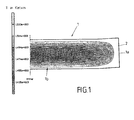
- the FIG. 1 shows a representation of a half of a slab 1 by means of false colors, a temperature distribution is made visible, the temperature is the warmer the brighter the color or gray level.
- the slab 1 is already heated unevenly when leaving a conventional furnace of a hot strip mill, which is also due to a too short Ofenverweilzeit, which can be the result of high furnace utilization.
- the slab 1 is at the surface and at the edge 1 a or at the slab edge 2 warmer than, for example, in the core 1 b, which is shown dark. The slab 1 is therefore not thoroughly warmed up.
- the temperature profile of the slab 1 changes, so that the rolled slabs 1, for example, receive a temperature profile that in the FIGS. 2 and 3 equivalent.
- the band edge 2 Cools down by the rolling on and there is a hot zone 3, which is the band edge 2 adjacent.
- the FIGS. 2 and 3 one recognizes the temperature distribution at the grayscale, whereby the darker the grayscale the lower the temperature.
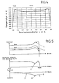
- FIG. 4 shows a profile of the mean strip temperature as a function of the width of a Vorbandes, which also clearly shows that the temperature drops at the edge of the tape and the inside is also a lower temperature. In a zone adjacent to the edge, the highest average temperature is present.
- FIG. 5 shows in three diagrams arranged one above the other a curve of the average temperature, a rolling force and the profile shape as a function of the width of the belt or the slab 1.
- the upper part of the figure shows the course of the average temperature as a function of the width, with different temperature profiles 4.5 at different points of the hot strip mill (oven, within the finishing mill).
- FIGS. 1 to 5 show for an application example the effect of uneven temperatures across the width.
- FIG. 6 shows in the upper picture a schematic view of a device 10 according to the invention for cooling a thin slab, a pre-strip or a belt 11.
- the belt 11 is guided laterally by adjustable side guides 12 and side guide means provided therefor.
- the side guides 12 are made laterally adjustable along the direction of the arrow 13.
- cooling elements 14, such as cooling nozzles are provided, which can be positioned at the location at which the highest temperature or high temperatures of the strip can be measured or expected, so that this area or these areas are cooled separately can be.
- a main cooling region 14a defined on the basis of the temperature distribution can be fixed and additionally cooled by means of a coolant, such as, for example, cooling water.
- the cooling water can be directed, for example, by means of hoses 15 to the nozzles 14, wherein the hoses 15 can be protected or shielded against the high ambient temperature.
- the device is shown in a side view.
- the belt is transported by means of the rollers and at the same time the belt is partially cooled by means of a coolant, such as cooling water or cooling air, at designated positions.
- a coolant such as cooling water or cooling air
- nozzles 14 are arranged above and below the belt so that it can be cooled both from below and / or from above.
- the coolant quantity depends on a target variable (eg the temperature distribution, target contour, flatness), or of other process parameters, such as the furnace drawing time, width, width reduction, etc., at the top and / or at the bottom individually is adjustable so that an optimized cooling of the corresponding band ranges can be done.
- a target variable eg the temperature distribution, target contour, flatness
- other process parameters such as the furnace drawing time, width, width reduction, etc.
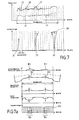
- the FIG. 7 shows in the upper picture a temperature distribution of a band, which is not distributed symmetrically. As can be seen, at or near the two edges, there are various wide regions of elevated temperature, with an area of elevated temperature also being found in the middle band region.
- the temperature profile behind the caster and / or behind the roughing stand and / or behind the furnace is shown in the upper curve 20 and the temperature profile behind the finishing line in the lower curve 21 is shown.
- the dot-dash lines 22, 23 are the desired or target values of the temperature distribution.
- Line 27 represents an average within a zone i.
- the arrangement of the nozzles is chosen. This is shown in the lower figure of FIG. 7 an array of nozzles at the locations where the temperature is excessive with respect to the setpoint.
- a nozzle 24 is arranged in the region of the left edge of the tape
- two nozzles 25 are arranged in the central region
- three nozzles 26 are provided in the region of the right edge of the tape.
- the amount of coolant 28 which is sprayed onto the belt can also be correspondingly distributed, so that a comparable coolant quantity distribution is present.
- FIG. 7 below shows a multi-zone cooling, in which the respective zones are individually adjustable for cooling.
- the Figure 7a for another example of use in the upper diagram, shows a distribution of the wave height or unevenness of a band as a function of the width of the band. In this case clearly two maxima 100,101 can be recognized.
- the second diagram from above the deformation of the rolling body of a work roll as a result of the belt cooling can be seen, the contour in the area the arrows 102,103 can detect a change of the roll gap, which can be seen at the positions of the maxima of the upper image.
- the third diagram from the top shows the specific rolling force as a function of the width, again showing maxima as a function of the width at the same point.
- the fourth diagram from the top shows a temperature distribution of a band that is not evenly distributed.
- FIG. 7a shows, for an alternative case study, schematically the operating principle of the invention, according to which a targeted strip cooling, see the lower diagram, is carried out at such locations, where a detected unevenness is detected, so that improved planarity is achieved behind the rolling line.
- the change of the flattening in the roll gap at the outlet stand or, if necessary, on several stands of a rolling train reduces or eliminates the unevenness.
- a trim of the temperature of the belt it is advantageous here, if the belt temperature tolerances are met.
- the Figure 7a shows in the lower diagram, the arrangement of the cooling nozzles 104 and thus a multi-zone cooling, in which the respective zones 105 are individually adjustable for cooling.
- An arrangement of individual nozzles in, for example, quarter wave range of the band is provided or possible.
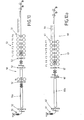
- FIG. 8 shows a device 30 with an array of nozzles 31,32 for cooling a slab or a belt 33, wherein the nozzles 31,32 are provided both under the belt or the slab and over the belt or the slab. This allows the nozzles to add the belt or slab Spray on both sides with a cooling medium so that the strip or slab is cooled on both sides at the relevant points.
- the nozzles 31, 32 are advantageously arranged in rows, so that adjacent nozzles can also be arranged overlapping.
- the nozzles also each have their own supply line 34, by means of which the coolant, such as water, can be moved to the nozzle 31, 32 before it is applied to the belt by means of the nozzle.
- the nozzles 31, 32 can advantageously be arranged in a fixed manner, wherein the nozzles 31, 32 can be connected by means of a holding frame or frame, or the nozzles 31, 32 can be self-supporting, wherein the nozzles 31, 32 can also be connected to one another.
- the nozzles 31, 32 can also be positionable, so that they can be kept adjustable in their position across the width.
- the nozzles 31, 32 can also be arranged in groups or in pairs, for example in pairs symmetrically.
- the nozzles may also have different nozzle cross-sections, or a plurality of nozzles may be connected one behind the other in the material flow direction.
- a desired different coolant quantity distribution (“water crown”) can be represented, in which larger nozzles are used in the edge region of the nozzle beam than in the middle region and even smaller nozzles in the middle.
- the FIG. 9 schematically shows a device 40 for processing tapes, such as a hot strip mill.
- the device 40 has a slab furnace 41 and two scale scrubbers 42,43.
- a first roughing stand 44 and second roughing stand 45 are provided, wherein the first roughing stand 44 can be formed as a continuous scaffold and the second roughing stand 45 can be designed as a reversing scaffold.
- side guides 46 provided, such as in front of or behind the roughing stands and before the scissors 49 '.
- the rolling means 47 such as a finishing train, are provided before the belt is cooled and wound on a reel, not shown.
- devices 48 for influencing the temperature of the strip are provided with nozzles.
- thermo measuring devices 49 such as temperature scanners, can be provided, which can be arranged after at least one of the roughing stands 44, 45 and / or after the rolling device 47.
- the devices 48 for influencing the temperature of the belt can be provided on the side guides in front of the roughing stands, such as continuous or reversing stand, and / or on the side guides in front of the scissors or in front of the finishing train 47.
- devices 48 for influencing the temperature with nozzle arrangements possible and advantageous. This can also apply to a plate mill in which such devices 48 can be provided to influence the temperature at the individual stages from the furnace to the heavy plate stand.
- FIG. 9a schematically shows another embodiment of a device 40 for processing tapes, such as a hot strip mill.
- the device 40 has a slab furnace 41 and at least two scale scrubbers 42,43.
- a first roughing stand 44 and second roughing stand 45 are provided, wherein the first roughing stand 44 can be designed as a continuous scaffold and the second roughing stand 45 can also be designed as a reversing scaffold.
- side guides 46 are provided, such as in front of the roughing frames 44 and before the scissors 49 '.
- the rolling means 47 such as a finishing train, provided before the tape is wound on a reel, not shown.
- devices 48 for influencing the temperature of the strip are provided with nozzles.
- devices 48 for influencing the temperature of the strip may also be provided in the area of the finishing train 47 between individual stands.
- the devices for influencing the temperature 48 are advantageously provided on the side guides there.
- such devices can also be provided in the region of a pre-belt cooler 46 ', which can be arranged in front of the finishing train.
- a pre-belt cooler 46 ' which can be arranged in front of the finishing train.
- at least a part of the cooling device may comprise a belt zone cooling.
- temperature measuring devices 49 such as temperature scanners, can be provided, which can be arranged after at least one of the roughing stands 44, 45 and / or after the rolling device 47.
- the devices 48 for influencing the temperature of the belt can be provided on the side guides in front of the roughing stands, such as continuous or reversing stand, and / or on the side guides in front of the scissors or in front of the finishing train 47.
- devices 48 for influencing the temperature with nozzle arrangements possible and advantageous. This can also apply to a plate mill in which such devices 48 can be provided to influence the temperature at the individual stages from the furnace to the heavy plate stand.
- the Figures 10 and 10b each show a so-called CSP plant (Compact Strip Production) 50 with Vorgerüst and the FIGS. 10a and 10c in each case a CSP plant 60 without Vorgerüst.
- CSP plant Compact Strip Production
- the CSP plant 50 of the FIG. 10 has temperature measuring devices 51 disposed in front of the roller hearth furnace 50a and after the mold and further one located at the end of the finishing train with the rolling stands F1, F2, F3, F4, F5 and F6.
- the devices 52 for influencing the temperature with the nozzles for cooling the slab or the belt are advantageously before and / or after the roller hearth furnace after the mold and / or in front of the roughing stand R1 and / or after the roughing stand R1 and / or before the finishing train.
- the plant of FIG. 10b differs from the plants of FIGS. 10 and 10a merely in that further cooling devices 52 are still provided in the finishing train 53 between the rolling stands F1 and F2, wherein within the finishing train 53 also further cooling devices 52 between other rolling stands F1, ..., F6 could be provided.
- the CSP plant 60 of the FIG. 10a has temperature measuring devices 61, in front of the roller hearth furnace 60a after the mold and at the end of the finishing train with the rolling stands F1, F2, F3, F4, F5, F6 and F7.
- the devices 62 for influencing the temperature with the nozzles for cooling the belt are advantageously to be arranged before and / or after the roller hearth furnace after the mold and / or in front of the finishing train.
- the plant of FIG. 10c differs from the plant of FIG. 10a merely in that further cooling devices 62 are still provided in the finishing train 63 between the rolling stands F1 and F2 and in the cooling section 64, wherein within the finishing train 63 also further cooling devices 62, for example between other rolling stands F1, ..., F6 be provided could.
- a temperature scanner 61 is provided at the end of the cooling section.
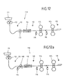
- FIGS. 11, 11a . 11b and 11c each show an endless thin slab plant 70,80, in which the casting plant and the rolling mill are directly coupled together.
- a particularly short investment is achieved.
- the time for a temperature compensation from the solidification of the melt to rolling is very short. Therefore, the provision of devices according to the invention for cooling a strip in such systems is particularly preferred, because a temperature compensation in the width direction with uneven temperature distribution without cooling devices can not be achieved.
- Buffalo of the cooling devices for example in the form of slab zone cooling or on the side guides can counter this can be actively worked and an adjustment of the temperature across the width can be actively carried out in different zones of strip production.
- FIG. 11 and the FIG. 11b each show in the system 70 temperature measuring devices 71, after the casting machine 70a and the roughing stands V1, V2, V3 and / or after heating 71 a, such as a roller hearth furnace or an inductive heating, and / or after the finishing mill with the rolling stands F1, F2, F3, F4 and F5 are arranged.
- the devices 72 for influencing the temperature or for cooling with the nozzles for cooling the belt are advantageously within and / or after the casting machine, before and / or after heating, as well as before and / or in the finishing train 73 between rolling stands F1, ... F5 arranged.
- a cooling section 78 is provided for the band after the finishing line.
- FIG. 11a and the FIG. 11c show in the system 80 temperature measuring devices 81, which are arranged after the casting machine 83 and the furnace or holding furnace 84 or after the inductive heating 85 and / or after the finishing mill 86 with the rolling stands F1, F2, F3, F4, F5, F6 and F7 are.
- the devices 82 for influencing the temperature or for cooling with the nozzles for cooling the slabs or the belt are advantageously within and / or after the casting machine 83, before and / or after the heating 84 or 85, as well as before and / or within the Finished line 86 between roll stands F1, ... F7 arranged.
- an inductive or other heating 87 is optionally provided in the finishing train 86 and after the finishing train a cooling section 88 for the band.
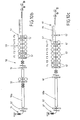
- the Figures 12 and 12a each show a thin-strip casting mill, in which the casting plant 111 essentially consists of casting rolls 112.
- the temperature sensors or temperature scanners 113 are arranged to determine the temperature distribution of the tape.
- devices for belt zone cooling 114 are provided, which are provided at the beginning of the installation and / or before and / or after rolling stands 115 can.
- the rolling mill may consist of one or more rolling stands 115.
- a band heater 116 is provided, which can be provided after a leveler 118 or a driver 117. In such thin strip systems, it is so that the band contour can hardly be influenced.
- the rolling gap of the rolling stands must be adjusted according to the entry profile.
- the multiply-mentioned actuators of the band zone cooling or the special local cooling at the entrance of the rolling stands or before or between rolling stands to improve the band flatness are advantageous.
- a two-sided cooling is possible.
- even a one-sided cooling, as from above or from below, can be carried out with a thin band and with deliberately delimited effect of the cooling.
- Comparable can also be made for a heavy plate line, in which after leaving the slab from the furnace to the heavy plate stand and in the downstream cooling section, a temperature control similar to the above can be performed. Also, a temperature influence over the width of the strip can also be carried out in a non-ferrous hot strip plant.
- All applications serve the purpose of homogenizing the strip temperature across the width by suitable cooling of the slab or strip over the strip width and to improve or specifically influence the contour or flatness.
- a flat jet nozzle, a conical nozzle, an air-water multi-fluid nozzle or a nozzle, such as a tube or tube arrangement of a laminar belt cooling can be used for cooling individual zones. Different nozzles can be used to cool different zones. Also, combined nozzle devices may be provided.
- the nozzles or the cooling zones over the width can also have a uniform or uneven distance from each other.
- a pre-strip cooling for example, a segment cooling in a continuous casting plant, an interstage cooling, a descaling, a nip cooling, a belt top or belt bottom cooling behind a looper or a cooling line can be used for cooling with the aforementioned objective and the corresponding properties or a combination of the above listed cooling devices.
- the roll gap cooling can be carried out, for example, essentially shortly before or immediately before the roll gap, by cooling the roll and / or the strip or the strip surface.
- cooling can also be provided in the case of a cold rolling train, so that the band flatness can be influenced at least indirectly by the cooling.
- nozzles for cooling on width-adjustable tape guides and nozzles may be provided such that they are to be arranged individually. Also, viewed over the width of the tape, a plurality of nozzles are provided, in each case only the nozzles are driven and distribute coolant, which are needed for cooling. Overall, such a multi-zone cooling can be realized.
- the FIG. 13 schematically shows a thin slab plant 90 with a casting machine 91, a roller hearth furnace 92 or induction heating, a finishing mill 93 with rolling devices F1 to F6 and with temperature sensors 94 and slab or belt cooling devices 95.
- the control unit 96 controls the belt cooling devices 95 based on the data of the temperature sensors 94, Furthermore, input variables are used for the determination of the coolant distribution and coolant quantity and the control of the respective nozzles of the coolant aggregates: the casting thickness of the slab or of the strip, the pre-strip thickness, the width of the strip, the width reduction, the strip material, the furnace or the furnace type, for example identifiable by the furnace number, the transport speed, the measured temperatures across the width of the strip.
- the effectiveness of the cooling can be further assessed, such as the relationship between the heat transfer coefficient and the amount of coolant, such as the amount of water, see block 97.
- FIG. 14 schematically shows a thin slab plant 90 with a casting machine 91, a roller hearth furnace 92, a finishing mill 93 with roller devices F1 to F6 and with temperature sensors 94 and belt cooling devices 95.
- the control unit 96 controls the belt cooling devices 95 on the basis of the data of the temperature sensors 94 and / or Bandplanheitssensors 98 and / or the strip profile measuring sensor 119, wherein furthermore the input variables mentioned in the last section can be used for the determination of the coolant distribution and coolant quantity and the control of the respective nozzles of the coolant aggregates.
- the effectiveness of the cooling may be assessed, such as the relationship between the heat transfer coefficient and the amount of coolant, such as the amount of water, see block 97.
- the unevenness and / or the band contour ie the relationship of the contour and / or flatness change, and a necessary cooling amount and a necessary cooling distribution determined and taken into account.
- the flatness and the deviation from the target flatness can be determined, for example, optically or by means of a tensile stress distribution.
- the band contour can be measured by the profile measuring sensor and thus the deviation of the measured band contour from the target contour can be calculated.
- Control circuits can also be provided by means of which the set target values or target functions are regulated with the use of measured variables.
- a temperature control loop can be provided, by means of which a measured strip temperature distribution, for example, behind a rolling train and / or a cooling line is used to control the cooling zones in terms of their cooling amount and cooling amount distribution in order to achieve a largely homogeneous temperature distribution of the strip.
- the width of the belt is divided into cooling zones and the cooling zones is assigned a temperature.
- the cooling method evaluates the available data and determines, depending on the input variables and with the knowledge of the cooling effect, which nozzles are activated or deactivated and which coolant quantity is to be adjusted at which nozzle, so that a substantially homogeneous temperature distribution results.
- a control loop can be provided, by means of which the band flatness is included in order to alternatively reach the end by suitable coolant distribution as possible a flat band.
- control circuit which takes into account the band contour in order to come closer to the target band contour (for example a parabola) as a further alternative by means of suitable coolant distribution.
Landscapes
- Engineering & Computer Science (AREA)
- Mechanical Engineering (AREA)
- Metal Rolling (AREA)
- Control Of Metal Rolling (AREA)
- Continuous Casting (AREA)
Claims (18)
- Dispositif pour influencer la répartition de température sur la largeur d'une brame ou d'une bande (33), en particulier dans une installation de laminage à chaud à une ou à plusieurs cages, dans lequel il est prévu au moins un dispositif de refroidissement avec des buses (14) pour envoyer un agent de refroidissement sur la brame ou sur la bande (33), lesdites buses (14) étant agencées et/ou pilotées de façon répartie sur la largeur,
caractérisé en ce que
l'une au moins des buses (14) est réglable quant à sa position par rapport à la largeur de la brame ou de la bande (33), et en ce que :- les buses (14) sont susceptibles d'être positionnées à l'endroit auquel il est possible de déterminer une température accrue de la brame ou de la bande (33), pour appliquer l'agent de refroidissement ; ou- en fonction d'un état de planéité observé de la bande, un agent de refroidissement peut être appliqué de manière commandée de telle façon que les défauts de planéité sont réduits ou éliminés ; ou- en fonction d'un contour mesuré de la bande, un agent de refroidissement peut être appliqué de manière commandée de telle façon que le contour de la bande se rapproche d'un contour cible souhaité. - Dispositif selon la revendication 1,
caractérisé en ce qu'il est prévu au moins un capteur de mesure (51), qui détecte la répartition de température d'une brame ou d'une bande - considérée sur la largeur de la brame ou de la bande - , de sorte que la buse du dispositif de refroidissement peut être pilotée en fonction du signal du capteur. - Dispositif selon la revendication 1,
caractérisé en ce qu'il est prévu au moins un capteur de mesure (98), qui détecte les défauts de planéité d'une bande - considérée sur la largeur de la bande -, en particulier derrière le train de laminage, de sorte que les buses à activer peuvent être choisies en fonction du signal du capteur. - Dispositif selon la revendication 1,
caractérisé en ce qu'il est prévu au moins un capteur de mesure (119), qui détecte le contour de la bande - considérée sur la largeur de la bande -, en particulier derrière le train de laminage, de sorte que les buses ou les zones du dispositif de refroidissement à activer peuvent être choisies en fonction du signal du capteur. - Dispositif selon la revendication 1, 2, 3 ou 4,
caractérisé en ce que la largeur de la brame ou de la bande (33) est subdivisée en zone de refroidissement et, pour au moins une zone, avantageusement pour plusieurs zones ou pour toutes les zones, il est respectivement prévu au moins une buse (14) du dispositif de refroidissement. - Dispositif selon l'une des revendications précédentes,
caractérisé en ce que les buses (14) sont agencées par paires et avantageusement symétriquement et par paires par rapport au milieu de la bande (33). - Dispositif selon la revendication 6,
caractérisé en ce que le déplacement des buses en largeur ou la position des buses a lieu par une fixation sur un guidage latéral de la brame ou de la bande. - Dispositif selon la revendication 6,
caractérisé en ce que le déplacement des buses en largeur ou la position des buses a lieu au moyen d'un dispositif de déplacement pour la moitié de droite et/ou la moitié de gauche de la brame ou de la bande, indépendamment l'une de l'autre. - Dispositif selon la revendication 8,
caractérisé en ce que les dispositifs de déplacement sont respectivement séparés. - Dispositif selon l'une des revendications précédentes,
caractérisé en ce que les buses (14) sont agencées les unes à côté des autres, et au moins une buse (14) est associée de préférence à chaque zone de refroidissement ou au moins une buse est associée à plusieurs zones de refroidissement. - Dispositif selon la revendication 10,
caractérisé en ce que les buses ou les zones de refroidissement présentent les unes par rapport aux autres une distance régulière ou irrégulière sur la largeur. - Dispositif selon la revendication 10,
caractérisé en ce que les formes ou les types de buses sont réalisé(e)s de façon différente sur la largeur pour ce qui concerne la quantité d'agent de refroidissement et/ou le motif de pulvérisation. - Dispositif selon l'une des revendications précédentes,
caractérisé en ce que les buses (14) sont agencées au-dessous et/ou au-dessus de la bande. - Dispositif selon l'une des revendications précédentes,
caractérisé en ce qu'il est prévu en outre une unité de commande (96), qui traite des grandeurs d'entrée pertinentes et qui détermine et pilote la quantité d'agent de refroidissement à appliquer pour la zone de refroidissement et/ou la position de refroidissement respectives. - Dispositif selon la revendication 14,
caractérisé en ce qu'il est prévu un circuit de régulation qui, en fonction de la répartition de température mesurée de la bande ou de la brame, pilote les buses à utiliser pour le refroidissement. - Dispositif selon la revendication 14,
caractérisé en ce qu'il est prévu un circuit de régulation qui, en fonction des défauts de planéité mesurés de la bande avant la dernière déformation, la refroidit de telle façon que la planéité de la bande est améliorée après la dernière déformation. - Dispositif selon la revendication 14,
caractérisé en ce qu'il est prévu un circuit de régulation qui, en fonction du contour mesuré de la bande, refroidit le matériau à laminer avant la dernière déformation de telle façon que le contour de la bande se rapproche du contour cible souhaité. - Utilisation d'un dispositif de refroidissement selon l'une au moins des revendications précédentes,
caractérisé en ce que le dispositif est agencé pour régulariser la température sur la largeur et/ou pour améliorer le contour ou la planéité sur l'un au moins des systèmes suivants d'un train de laminage :i. Refroidissement des segments dans une installation de coulée continue,ii. Refroidissement des brames minces derrière une installation de coulée continue,iii. Refroidissement d'une bande coulée derrière l'installation de coulée,iv. Refroidissement préliminaire de la bande dans un train de laminage à chaud traditionnel,v. Refroidissement intermédiaire des cages,vi. Refroidissement de l'emprise de laminage,vii. Train de refroidissement,viii. Guidage latéral avant et/ou après une cage préparatoire et/ou une cage finisseuse,ix. ou bien une combinaison de ces systèmes.
Applications Claiming Priority (4)
| Application Number | Priority Date | Filing Date | Title |
|---|---|---|---|
| DE102007025287 | 2007-05-30 | ||
| DE102007026578 | 2007-06-08 | ||
| DE102007053523A DE102007053523A1 (de) | 2007-05-30 | 2007-11-09 | Vorrichtung zur Beeinflussung der Temperaturverteilung über der Breite |
| PCT/EP2008/002643 WO2008145222A1 (fr) | 2007-05-30 | 2008-04-03 | Dispositif pour influer sur la répartition de température sur une largeur |
Publications (2)
| Publication Number | Publication Date |
|---|---|
| EP2155411A1 EP2155411A1 (fr) | 2010-02-24 |
| EP2155411B1 true EP2155411B1 (fr) | 2013-01-23 |
Family
ID=39917502
Family Applications (1)
| Application Number | Title | Priority Date | Filing Date |
|---|---|---|---|
| EP08734984A Revoked EP2155411B1 (fr) | 2007-05-30 | 2008-04-03 | Dispositif pour influer sur la répartition de température sur une largeur |
Country Status (11)
| Country | Link |
|---|---|
| US (1) | US9180504B2 (fr) |
| EP (1) | EP2155411B1 (fr) |
| JP (1) | JP5079875B2 (fr) |
| KR (1) | KR101138725B1 (fr) |
| CN (1) | CN101678419B (fr) |
| CA (2) | CA2679336C (fr) |
| DE (1) | DE102007053523A1 (fr) |
| ES (1) | ES2400536T3 (fr) |
| RU (2) | RU2009148767A (fr) |
| TW (1) | TWI442982B (fr) |
| WO (1) | WO2008145222A1 (fr) |
Families Citing this family (37)
| Publication number | Priority date | Publication date | Assignee | Title |
|---|---|---|---|---|
| DE102008032932A1 (de) * | 2008-07-12 | 2010-01-14 | Sms Siemag Aktiengesellschaft | Verfahren zum Längsführen eines Walzgutes, insbesondere eines warmgewalzten Stahlbandes und Warmwalzwerk zur Durchführung des Verfahrens |
| FR2940978B1 (fr) * | 2009-01-09 | 2011-11-11 | Fives Stein | Procede et section de refroidissement d'une bande metallique en defilement par projection d'un liquide |
| CN101780478B (zh) * | 2009-01-21 | 2012-07-04 | 中冶赛迪工程技术股份有限公司 | 一种热轧带钢及钢板板形和精度控制的方法和设备 |
| JP5776874B2 (ja) * | 2011-02-14 | 2015-09-09 | 住友電気工業株式会社 | マグネシウム合金圧延材、およびマグネシウム合金部材、ならびにマグネシウム合金圧延材の製造方法 |
| EP2527054A1 (fr) | 2011-05-24 | 2012-11-28 | Siemens Aktiengesellschaft | Procédé de commande pour une voie de laminage |
| EP2527053A1 (fr) | 2011-05-24 | 2012-11-28 | Siemens Aktiengesellschaft | Procédé de commande pour une voie de laminage |
| US9566625B2 (en) | 2011-06-07 | 2017-02-14 | Nippon Steel & Sumitomo Metal Corporation | Apparatus for cooling hot-rolled steel sheet |
| US9186710B2 (en) * | 2011-06-07 | 2015-11-17 | Nippon Steel & Sumitomo Metal Corporation | Method for cooling hot-rolled steel sheet |
| US9211574B2 (en) * | 2011-07-27 | 2015-12-15 | Nippon Steel & Sumitomo Metal Corporation | Method for manufacturing steel sheet |
| KR101400501B1 (ko) * | 2012-03-29 | 2014-05-27 | 현대제철 주식회사 | 슬라브용 스케일 제거장치 |
| EP2841215B1 (fr) | 2012-04-27 | 2016-05-18 | Primetals Technologies Germany GmbH | Adaptation des propriétés d'une bande par refroidissement préalable de la bande dans le sens de sa largeur |
| US9889480B2 (en) | 2013-03-11 | 2018-02-13 | Novelis Inc. | Flatness of a rolled strip |
| DE102013221710A1 (de) | 2013-10-25 | 2015-04-30 | Sms Siemag Aktiengesellschaft | Aluminium-Warmbandwalzstraße und Verfahren zum Warmwalzen eines Aluminium-Warmbandes |
| EP2982453A1 (fr) * | 2014-08-06 | 2016-02-10 | Primetals Technologies Austria GmbH | Réglage d'un profil de température ciblé sur une tête de bande et pied de bande devant la partie transversale d'une bande métallique |
| CN104475860B (zh) * | 2014-12-31 | 2017-02-22 | 中铝西南铝冷连轧板带有限公司 | 切边装置在生产卷材时的圆盘剪宽度设定方法 |
| EP3138639B1 (fr) * | 2015-09-03 | 2021-03-24 | SMS group GmbH | Procede de production d'une bande metallique par laminage en continu |
| DE102015223787A1 (de) * | 2015-10-09 | 2017-04-13 | Sms Group Gmbh | Verfahren und Vorrichtung zum Herstellen eines metallischen Bandes durch Endloswalzen |
| JP6410050B2 (ja) * | 2015-11-19 | 2018-10-24 | トヨタ自動車株式会社 | 冷却用噴射ノズルの設計方法 |
| KR101746985B1 (ko) * | 2015-12-23 | 2017-06-14 | 주식회사 포스코 | 냉각장치 및 냉각방법 |
| PL3445507T3 (pl) * | 2016-05-11 | 2020-11-30 | Nucor Corporation | Kontrola zmiany temperatury taśmy przy bezpośrednim odlewaniu taśm |
| WO2018055718A1 (fr) * | 2016-09-23 | 2018-03-29 | 東芝三菱電機産業システム株式会社 | Dispositif de commande de chauffage de bord |
| EP3318342A1 (fr) * | 2016-11-07 | 2018-05-09 | Primetals Technologies Austria GmbH | Procédé de fonctionnement d'un ensemble de coulée-laminage |
| WO2018111048A1 (fr) * | 2016-12-16 | 2018-06-21 | 주식회사 포스코 | Système de refroidissement |
| CA3051821C (fr) * | 2017-03-31 | 2022-05-31 | Nippon Steel Corporation | Dispositif de refroidissement d'une tole en acier laminee a chaud et methode de refroidissement de ladite tole |
| DE102017206540A1 (de) * | 2017-04-18 | 2018-10-18 | Sms Group Gmbh | Vorrichtung und Verfahren zum Kühlen von Metallbändern oder -blechen |
| EP3395463B1 (fr) | 2017-04-26 | 2019-12-25 | Primetals Technologies Austria GmbH | Refroidissement d'un laminé |
| JP6897609B2 (ja) * | 2018-03-08 | 2021-06-30 | Jfeスチール株式会社 | 熱間圧延装置及び熱延鋼板の製造方法 |
| CN110276084B (zh) * | 2018-03-15 | 2022-11-11 | 上海梅山钢铁股份有限公司 | 热连轧机防剥落水水量分布方法 |
| DE102018211177A1 (de) | 2018-04-13 | 2019-10-17 | Sms Group Gmbh | Kühleinrichtung zum Kühlen eines metallischen Gutes sowie Verfahren zu deren Herstellung und Betrieb |
| DE102018205684A1 (de) | 2018-04-13 | 2019-10-17 | Sms Group Gmbh | Kühleinrichtung und Verfahren zu deren Betrieb |
| DE102018205685A1 (de) * | 2018-04-13 | 2019-10-17 | Sms Group Gmbh | Kühleinrichtung und Verfahren zu deren Betrieb |
| BR112021003034A2 (pt) | 2018-09-19 | 2021-05-11 | Nippon Steel Corporation | dispositivo de resfriamento para chapa de aço laminada a quente e método de resfriamento de chapa de aço laminada a quente |
| EP3670011B1 (fr) | 2018-12-21 | 2022-09-28 | Primetals Technologies Austria GmbH | Refroidissement de la bande métallique dans une cage de laminoir |
| DE102019208462A1 (de) * | 2019-06-11 | 2020-12-17 | Sms Group Gmbh | Sequenzielles Kühlen von metallischen Breitflachprodukten |
| CN110404964B (zh) * | 2019-07-08 | 2020-07-31 | 中南大学 | 一种宽度方向差性能铝合金带材的轧制制备方法 |
| EP3895821B1 (fr) | 2020-04-14 | 2023-03-15 | ABB Schweiz AG | Détection d'unités de refroidissement défectueuses configurées pour fournir du liquide de refroidissement aux laminoirs |
| CN113652622A (zh) * | 2021-08-16 | 2021-11-16 | 燕山大学 | 一种适合于镀锌机组风机冷却工艺优化方法及系统 |
Family Cites Families (30)
| Publication number | Priority date | Publication date | Assignee | Title |
|---|---|---|---|---|
| US2271372A (en) * | 1939-04-10 | 1942-01-27 | Francis J Herman | Method of treating strip metal |
| CH572370A5 (fr) * | 1974-02-28 | 1976-02-13 | Concast Ag | |
| JPS594201B2 (ja) * | 1975-08-04 | 1984-01-28 | 新日本製鐵株式会社 | コウハンノセイゾウホウホウ |
| DE2636666C2 (de) * | 1976-08-14 | 1978-06-29 | Demag Ag, 4100 Duisburg | Spritzdüsen-Anordnung für Metall-, insbesondere für StahlstranggieBanlagen für extrem breite Stahlbrammen |
| SU778845A1 (ru) | 1979-01-15 | 1980-11-15 | Донецкий Ордена Трудового Красного Знамени Политехнический Институт | Устройство дл регулировани толщины полосы |
| SU863039A1 (ru) | 1979-06-28 | 1981-09-25 | Череповецкий Филиал Северо-Западного Заочного Политехнического Института | Способ управлени тепловым профилем валков прокатных станов |
| SU904820A1 (ru) | 1979-11-30 | 1982-02-15 | Липецкий политехнический институт | Способ регулировани формы полосы при листовой прокатке |
| SU1031548A1 (ru) | 1982-04-13 | 1983-07-30 | Череповецкий Филиал Северо-Западного Заочного Политехнического Института | Способ управлени тепловым профилем валков листовых прокатных станов |
| GB8326652D0 (en) | 1983-10-05 | 1983-11-09 | Davy Mckee Sheffield | Rolling mill |
| JPS60174833A (ja) * | 1984-02-20 | 1985-09-09 | Nippon Steel Corp | 熱鋼板の冷却方法 |
| JPS60235015A (ja) | 1984-05-07 | 1985-11-21 | Reiichiro Kawashima | カ−ソル付きスタツフ |
| JPH06244B2 (ja) * | 1984-05-09 | 1994-01-05 | 三菱電機株式会社 | 板材の形状制御装置 |
| JPS60238015A (ja) * | 1984-05-10 | 1985-11-26 | Mitsubishi Electric Corp | 熱間圧延機における圧延温度・板形状制御装置 |
| US4706480A (en) * | 1985-10-11 | 1987-11-17 | Svatos Joseph D | Rolling mill cooling system |
| JPS62158825A (ja) * | 1985-12-28 | 1987-07-14 | Nippon Steel Corp | 熱間圧延鋼板の冷却方法 |
| SU1371730A1 (ru) | 1986-04-21 | 1988-02-07 | Институт черной металлургии | Способ прокатки полос |
| JPS63115603A (ja) * | 1986-11-05 | 1988-05-20 | Nkk Corp | チタン材の熱間圧延時における表面疵の発生防止方法 |
| JPH05228525A (ja) * | 1992-02-19 | 1993-09-07 | Sumitomo Metal Ind Ltd | 熱間圧延鋼帯の幅方向温度制御方法および装置 |
| DE69324566T2 (de) | 1992-06-23 | 1999-10-28 | Nkk Corp., Tokio/Tokyo | Kühlungsvorrichtung und -verfahren für metallband |
| JPH0671328A (ja) * | 1992-08-28 | 1994-03-15 | Kawasaki Steel Corp | 熱延鋼板の冷却制御装置 |
| US5634360A (en) * | 1992-09-21 | 1997-06-03 | Ishikawajima-Harima Heavy Industries Co., Ltd. | Guiding apparatus for roughing mill |
| ATE211031T1 (de) * | 1995-11-20 | 2002-01-15 | Sms Demag Ag | Vorrichtung zur beeinflussung des profils von gewalztem walzband |
| DE19613718C1 (de) | 1996-03-28 | 1997-10-23 | Mannesmann Ag | Verfahren und Anlage zur Herstellung von warmgewalztem Stahlband |
| US6062056A (en) * | 1998-02-18 | 2000-05-16 | Tippins Incorporated | Method and apparatus for cooling a steel strip |
| DE10116273A1 (de) * | 2001-03-31 | 2002-10-10 | Sms Demag Ag | Verfahren zum Betreiben einer Walzstraße sowie eine entsprechend ausgebildete Walzstraße |
| RU2247617C1 (ru) | 2003-09-29 | 2005-03-10 | Руденко Ростислав Владимирович | Устройство для подачи жидкости на поверхность проката |
| JP2005238304A (ja) * | 2004-02-27 | 2005-09-08 | Jfe Steel Kk | 熱延鋼板の製造方法 |
| AT501314B1 (de) | 2004-10-13 | 2012-03-15 | Voest Alpine Ind Anlagen | Verfahren und vorrichtung zum kontinuierlichen herstellen eines dünnen metallbandes |
| DE102005029461B3 (de) * | 2005-06-24 | 2006-12-07 | Siemens Ag | Verfahren zum Aufbringen eines Kühlmittels und Walzgerüst zur Durchführung des Verfahrens |
| US20110036555A1 (en) * | 2007-08-28 | 2011-02-17 | Air Products And Chemicals, Inc. | Method and apparatus for discharging a non-linear cryogen spray across the width of a mill stand |
-
2007
- 2007-11-09 DE DE102007053523A patent/DE102007053523A1/de not_active Withdrawn
-
2008
- 2008-04-03 CA CA2679336A patent/CA2679336C/fr not_active Expired - Fee Related
- 2008-04-03 KR KR1020097018836A patent/KR101138725B1/ko active IP Right Grant
- 2008-04-03 RU RU2009148767/02A patent/RU2009148767A/ru not_active Application Discontinuation
- 2008-04-03 CN CN200880018106.7A patent/CN101678419B/zh not_active Expired - Fee Related
- 2008-04-03 ES ES08734984T patent/ES2400536T3/es active Active
- 2008-04-03 US US12/451,490 patent/US9180504B2/en not_active Expired - Fee Related
- 2008-04-03 EP EP08734984A patent/EP2155411B1/fr not_active Revoked
- 2008-04-03 JP JP2010509695A patent/JP5079875B2/ja not_active Expired - Fee Related
- 2008-04-03 CA CA2761271A patent/CA2761271A1/fr not_active Abandoned
- 2008-04-03 WO PCT/EP2008/002643 patent/WO2008145222A1/fr active Application Filing
- 2008-04-07 TW TW097112454A patent/TWI442982B/zh not_active IP Right Cessation
-
2011
- 2011-09-23 RU RU2011139125/02A patent/RU2488456C2/ru active
Also Published As
| Publication number | Publication date |
|---|---|
| KR20090130234A (ko) | 2009-12-21 |
| RU2011139125A (ru) | 2013-03-27 |
| ES2400536T3 (es) | 2013-04-10 |
| US9180504B2 (en) | 2015-11-10 |
| WO2008145222A1 (fr) | 2008-12-04 |
| KR101138725B1 (ko) | 2012-04-25 |
| CN101678419A (zh) | 2010-03-24 |
| TWI442982B (zh) | 2014-07-01 |
| CN101678419B (zh) | 2016-12-28 |
| US20100132426A1 (en) | 2010-06-03 |
| JP5079875B2 (ja) | 2012-11-21 |
| RU2488456C2 (ru) | 2013-07-27 |
| CA2679336A1 (fr) | 2008-12-04 |
| DE102007053523A1 (de) | 2008-12-04 |
| RU2009148767A (ru) | 2011-07-10 |
| JP2010527797A (ja) | 2010-08-19 |
| EP2155411A1 (fr) | 2010-02-24 |
| CA2761271A1 (fr) | 2008-12-04 |
| TW200906507A (en) | 2009-02-16 |
| CA2679336C (fr) | 2011-12-20 |
Similar Documents
| Publication | Publication Date | Title |
|---|---|---|
| EP2155411B1 (fr) | Dispositif pour influer sur la répartition de température sur une largeur | |
| EP1799368B1 (fr) | Procede et dispositif de production continue d'une fine bande metallique | |
| EP1951916B1 (fr) | Procede et train de laminoir de finition pour laminer a chaud un materiau de depart | |
| DE69202088T2 (de) | Vorrichtung und Verfahren zur Herstellung von warmgewalztem Stahl. | |
| EP0326190A2 (fr) | Installation pour fabriquer un feuillard d'acier ayant une épaisseur située entre 2 et 25 mm | |
| EP2651578B1 (fr) | Train de laminoir pour la production d'acier tubulaire et de bandes minces | |
| EP3658305B1 (fr) | Dispositif de refroidissement de cage permettant le refroidissement d'un feuillard en acier dans une cage de laminoir | |
| EP0121148A1 (fr) | Procédé pour la fabrication de feuillard à chaud avec section et planéité de bande de haute qualité | |
| EP2507399A1 (fr) | Laminoir à chaud et procédé de laminage à chaud d'un feuillard ou d'une tôle | |
| EP0906797B1 (fr) | Procédé et installation de dressage d'une bande métallique dans une installation de laminage à chaud | |
| EP2344287B1 (fr) | Procédé et dispositif pour le refroidissement d'une bande préliminaire ou d'une bande d'une ligne continue métallique dans un laminoir à chaud | |
| DE10163070A1 (de) | Verfahren und Einrichtung zum kontrollierten Richten und Kühlen von aus einem Warmband-Walzwerk auslaufendem breiten Metallband, insbesondere von Stahlband oder Blech | |
| WO2010149351A1 (fr) | Dispositif et procédé pour couler horizontalement un feuillard métallique | |
| WO2016165933A1 (fr) | Installation de coulée et de laminage et procédé servant à faire fonctionner ladite installation | |
| DE10056847A1 (de) | Warmwalzverfahren und Steckel-Walzwerksystem | |
| EP3589436A1 (fr) | Procédé et dispositif permettant la fabrication en continu d'un feuillard d'acier | |
| EP0732979B1 (fr) | Installation de coulee continue et de laminage pour bandes d'acier et systeme de reglage connexe | |
| DE4243857C1 (de) | Verfahren zum Herstellen eines Stahlbandes durch Gießen eines Stranges und anschließendes Walzen | |
| EP3441157A1 (fr) | Procédé et dispositif pour la coulée continue d'un produit métallique | |
| EP3284546A1 (fr) | Procédé de laminage d'un produit laminé dans un train de laminoir et train de laminoir | |
| EP3027331B1 (fr) | Installation de laminage de coulée continue et procédé de fabrication de brames | |
| EP1827735B1 (fr) | Procede et dispositif de coulee en bande de metaux | |
| AT525283B1 (de) | Verfahren zur Herstellung eines Dualphasenstahlbands in einer Gieß-Walz-Verbundanlage, ein mit dem Verfahren hergestelltes Dualphasenstahlband und eine Gieß-Walz-Verbundanlage | |
| AT525563B1 (de) | Trockengiessen in einer giess-walz-verbundanlage | |
| DE102016224822A1 (de) | Verfahren zum Walzen eines Walzguts in einer Walzstraße und Walzstraße |
Legal Events
| Date | Code | Title | Description |
|---|---|---|---|
| PUAI | Public reference made under article 153(3) epc to a published international application that has entered the european phase |
Free format text: ORIGINAL CODE: 0009012 |
|
| 17P | Request for examination filed |
Effective date: 20091230 |
|
| AK | Designated contracting states |
Kind code of ref document: A1 Designated state(s): AT BE BG CH CY CZ DE DK EE ES FI FR GB GR HR HU IE IS IT LI LT LU LV MC MT NL NO PL PT RO SE SI SK TR |
|
| AX | Request for extension of the european patent |
Extension state: AL BA MK RS |
|
| DAX | Request for extension of the european patent (deleted) | ||
| 17Q | First examination report despatched |
Effective date: 20120110 |
|
| GRAP | Despatch of communication of intention to grant a patent |
Free format text: ORIGINAL CODE: EPIDOSNIGR1 |
|
| GRAS | Grant fee paid |
Free format text: ORIGINAL CODE: EPIDOSNIGR3 |
|
| GRAA | (expected) grant |
Free format text: ORIGINAL CODE: 0009210 |
|
| AK | Designated contracting states |
Kind code of ref document: B1 Designated state(s): AT BE BG CH CY CZ DE DK EE ES FI FR GB GR HR HU IE IS IT LI LT LU LV MC MT NL NO PL PT RO SE SI SK TR |
|
| REG | Reference to a national code |
Ref country code: GB Ref legal event code: FG4D Free format text: NOT ENGLISH |
|
| REG | Reference to a national code |
Ref country code: CH Ref legal event code: EP |
|
| REG | Reference to a national code |
Ref country code: AT Ref legal event code: REF Ref document number: 594664 Country of ref document: AT Kind code of ref document: T Effective date: 20130215 Ref country code: CH Ref legal event code: EP |
|
| REG | Reference to a national code |
Ref country code: IE Ref legal event code: FG4D Free format text: LANGUAGE OF EP DOCUMENT: GERMAN |
|
| REG | Reference to a national code |
Ref country code: DE Ref legal event code: R096 Ref document number: 502008009172 Country of ref document: DE Effective date: 20130321 |
|
| REG | Reference to a national code |
Ref country code: ES Ref legal event code: FG2A Ref document number: 2400536 Country of ref document: ES Kind code of ref document: T3 Effective date: 20130410 |
|
| REG | Reference to a national code |
Ref country code: LT Ref legal event code: MG4D |
|
| REG | Reference to a national code |
Ref country code: NL Ref legal event code: VDEP Effective date: 20130123 |
|
| PG25 | Lapsed in a contracting state [announced via postgrant information from national office to epo] |
Ref country code: BG Free format text: LAPSE BECAUSE OF FAILURE TO SUBMIT A TRANSLATION OF THE DESCRIPTION OR TO PAY THE FEE WITHIN THE PRESCRIBED TIME-LIMIT Effective date: 20130423 Ref country code: SE Free format text: LAPSE BECAUSE OF FAILURE TO SUBMIT A TRANSLATION OF THE DESCRIPTION OR TO PAY THE FEE WITHIN THE PRESCRIBED TIME-LIMIT Effective date: 20130123 Ref country code: LT Free format text: LAPSE BECAUSE OF FAILURE TO SUBMIT A TRANSLATION OF THE DESCRIPTION OR TO PAY THE FEE WITHIN THE PRESCRIBED TIME-LIMIT Effective date: 20130123 Ref country code: IS Free format text: LAPSE BECAUSE OF FAILURE TO SUBMIT A TRANSLATION OF THE DESCRIPTION OR TO PAY THE FEE WITHIN THE PRESCRIBED TIME-LIMIT Effective date: 20130523 Ref country code: NO Free format text: LAPSE BECAUSE OF FAILURE TO SUBMIT A TRANSLATION OF THE DESCRIPTION OR TO PAY THE FEE WITHIN THE PRESCRIBED TIME-LIMIT Effective date: 20130423 |
|
| PG25 | Lapsed in a contracting state [announced via postgrant information from national office to epo] |
Ref country code: GR Free format text: LAPSE BECAUSE OF FAILURE TO SUBMIT A TRANSLATION OF THE DESCRIPTION OR TO PAY THE FEE WITHIN THE PRESCRIBED TIME-LIMIT Effective date: 20130424 Ref country code: FI Free format text: LAPSE BECAUSE OF FAILURE TO SUBMIT A TRANSLATION OF THE DESCRIPTION OR TO PAY THE FEE WITHIN THE PRESCRIBED TIME-LIMIT Effective date: 20130123 Ref country code: NL Free format text: LAPSE BECAUSE OF FAILURE TO SUBMIT A TRANSLATION OF THE DESCRIPTION OR TO PAY THE FEE WITHIN THE PRESCRIBED TIME-LIMIT Effective date: 20130123 Ref country code: PL Free format text: LAPSE BECAUSE OF FAILURE TO SUBMIT A TRANSLATION OF THE DESCRIPTION OR TO PAY THE FEE WITHIN THE PRESCRIBED TIME-LIMIT Effective date: 20130123 Ref country code: SI Free format text: LAPSE BECAUSE OF FAILURE TO SUBMIT A TRANSLATION OF THE DESCRIPTION OR TO PAY THE FEE WITHIN THE PRESCRIBED TIME-LIMIT Effective date: 20130123 Ref country code: LV Free format text: LAPSE BECAUSE OF FAILURE TO SUBMIT A TRANSLATION OF THE DESCRIPTION OR TO PAY THE FEE WITHIN THE PRESCRIBED TIME-LIMIT Effective date: 20130123 Ref country code: PT Free format text: LAPSE BECAUSE OF FAILURE TO SUBMIT A TRANSLATION OF THE DESCRIPTION OR TO PAY THE FEE WITHIN THE PRESCRIBED TIME-LIMIT Effective date: 20130523 |
|
| PG25 | Lapsed in a contracting state [announced via postgrant information from national office to epo] |
Ref country code: HR Free format text: LAPSE BECAUSE OF FAILURE TO SUBMIT A TRANSLATION OF THE DESCRIPTION OR TO PAY THE FEE WITHIN THE PRESCRIBED TIME-LIMIT Effective date: 20130123 |
|
| PLBI | Opposition filed |
Free format text: ORIGINAL CODE: 0009260 |
|
| BERE | Be: lapsed |
Owner name: SMS SIEMAG AG Effective date: 20130430 |
|
| PG25 | Lapsed in a contracting state [announced via postgrant information from national office to epo] |
Ref country code: RO Free format text: LAPSE BECAUSE OF FAILURE TO SUBMIT A TRANSLATION OF THE DESCRIPTION OR TO PAY THE FEE WITHIN THE PRESCRIBED TIME-LIMIT Effective date: 20130123 Ref country code: SK Free format text: LAPSE BECAUSE OF FAILURE TO SUBMIT A TRANSLATION OF THE DESCRIPTION OR TO PAY THE FEE WITHIN THE PRESCRIBED TIME-LIMIT Effective date: 20130123 Ref country code: DK Free format text: LAPSE BECAUSE OF FAILURE TO SUBMIT A TRANSLATION OF THE DESCRIPTION OR TO PAY THE FEE WITHIN THE PRESCRIBED TIME-LIMIT Effective date: 20130123 Ref country code: EE Free format text: LAPSE BECAUSE OF FAILURE TO SUBMIT A TRANSLATION OF THE DESCRIPTION OR TO PAY THE FEE WITHIN THE PRESCRIBED TIME-LIMIT Effective date: 20130123 Ref country code: CZ Free format text: LAPSE BECAUSE OF FAILURE TO SUBMIT A TRANSLATION OF THE DESCRIPTION OR TO PAY THE FEE WITHIN THE PRESCRIBED TIME-LIMIT Effective date: 20130123 |
|
| PLAX | Notice of opposition and request to file observation + time limit sent |
Free format text: ORIGINAL CODE: EPIDOSNOBS2 |
|
| 26 | Opposition filed |
Opponent name: SIEMENS VAI METALS TECHNOLOGIES GMBH Effective date: 20131023 |
|
| PG25 | Lapsed in a contracting state [announced via postgrant information from national office to epo] |
Ref country code: MC Free format text: LAPSE BECAUSE OF FAILURE TO SUBMIT A TRANSLATION OF THE DESCRIPTION OR TO PAY THE FEE WITHIN THE PRESCRIBED TIME-LIMIT Effective date: 20130123 Ref country code: CY Free format text: LAPSE BECAUSE OF FAILURE TO SUBMIT A TRANSLATION OF THE DESCRIPTION OR TO PAY THE FEE WITHIN THE PRESCRIBED TIME-LIMIT Effective date: 20130123 |
|
| REG | Reference to a national code |
Ref country code: CH Ref legal event code: PL |
|
| REG | Reference to a national code |
Ref country code: DE Ref legal event code: R026 Ref document number: 502008009172 Country of ref document: DE Effective date: 20131023 |
|
| REG | Reference to a national code |
Ref country code: IE Ref legal event code: MM4A |
|
| PG25 | Lapsed in a contracting state [announced via postgrant information from national office to epo] |
Ref country code: CH Free format text: LAPSE BECAUSE OF NON-PAYMENT OF DUE FEES Effective date: 20130430 Ref country code: LI Free format text: LAPSE BECAUSE OF NON-PAYMENT OF DUE FEES Effective date: 20130430 Ref country code: BE Free format text: LAPSE BECAUSE OF NON-PAYMENT OF DUE FEES Effective date: 20130430 |
|
| REG | Reference to a national code |
Ref country code: FR Ref legal event code: ST Effective date: 20131231 |
|
| PG25 | Lapsed in a contracting state [announced via postgrant information from national office to epo] |
Ref country code: FR Free format text: LAPSE BECAUSE OF NON-PAYMENT OF DUE FEES Effective date: 20130430 |
|
| PLAF | Information modified related to communication of a notice of opposition and request to file observations + time limit |
Free format text: ORIGINAL CODE: EPIDOSCOBS2 |
|
| PG25 | Lapsed in a contracting state [announced via postgrant information from national office to epo] |
Ref country code: IE Free format text: LAPSE BECAUSE OF NON-PAYMENT OF DUE FEES Effective date: 20130403 |
|
| PLBB | Reply of patent proprietor to notice(s) of opposition received |
Free format text: ORIGINAL CODE: EPIDOSNOBS3 |
|
| PG25 | Lapsed in a contracting state [announced via postgrant information from national office to epo] |
Ref country code: MT Free format text: LAPSE BECAUSE OF FAILURE TO SUBMIT A TRANSLATION OF THE DESCRIPTION OR TO PAY THE FEE WITHIN THE PRESCRIBED TIME-LIMIT Effective date: 20130123 |
|
| PG25 | Lapsed in a contracting state [announced via postgrant information from national office to epo] |
Ref country code: TR Free format text: LAPSE BECAUSE OF FAILURE TO SUBMIT A TRANSLATION OF THE DESCRIPTION OR TO PAY THE FEE WITHIN THE PRESCRIBED TIME-LIMIT Effective date: 20130123 |
|
| RAP2 | Party data changed (patent owner data changed or rights of a patent transferred) |
Owner name: SMS GROUP GMBH |
|
| PG25 | Lapsed in a contracting state [announced via postgrant information from national office to epo] |
Ref country code: LU Free format text: LAPSE BECAUSE OF NON-PAYMENT OF DUE FEES Effective date: 20130403 Ref country code: HU Free format text: LAPSE BECAUSE OF FAILURE TO SUBMIT A TRANSLATION OF THE DESCRIPTION OR TO PAY THE FEE WITHIN THE PRESCRIBED TIME-LIMIT; INVALID AB INITIO Effective date: 20080403 |
|
| REG | Reference to a national code |
Ref country code: DE Ref legal event code: R082 Ref document number: 502008009172 Country of ref document: DE Representative=s name: HEMMERICH & KOLLEGEN, DE Ref country code: DE Ref legal event code: R081 Ref document number: 502008009172 Country of ref document: DE Owner name: SMS GROUP GMBH, DE Free format text: FORMER OWNER: SMS SIEMAG AG, 40237 DUESSELDORF, DE |
|
| PLAB | Opposition data, opponent's data or that of the opponent's representative modified |
Free format text: ORIGINAL CODE: 0009299OPPO |
|
| R26 | Opposition filed (corrected) |
Opponent name: PRIMETALS TECHNOLOGIES AUSTRIA GMBH Effective date: 20131023 |
|
| APAH | Appeal reference modified |
Free format text: ORIGINAL CODE: EPIDOSCREFNO |
|
| APBM | Appeal reference recorded |
Free format text: ORIGINAL CODE: EPIDOSNREFNO |
|
| APBP | Date of receipt of notice of appeal recorded |
Free format text: ORIGINAL CODE: EPIDOSNNOA2O |
|
| APBQ | Date of receipt of statement of grounds of appeal recorded |
Free format text: ORIGINAL CODE: EPIDOSNNOA3O |
|
| REG | Reference to a national code |
Ref country code: DE Ref legal event code: R064 Ref document number: 502008009172 Country of ref document: DE Ref country code: DE Ref legal event code: R103 Ref document number: 502008009172 Country of ref document: DE |
|
| APBU | Appeal procedure closed |
Free format text: ORIGINAL CODE: EPIDOSNNOA9O |
|
| PGFP | Annual fee paid to national office [announced via postgrant information from national office to epo] |
Ref country code: ES Payment date: 20200629 Year of fee payment: 13 Ref country code: DE Payment date: 20200420 Year of fee payment: 13 |
|
| PGFP | Annual fee paid to national office [announced via postgrant information from national office to epo] |
Ref country code: IT Payment date: 20200428 Year of fee payment: 13 Ref country code: GB Payment date: 20200427 Year of fee payment: 13 |
|
| PGFP | Annual fee paid to national office [announced via postgrant information from national office to epo] |
Ref country code: AT Payment date: 20200421 Year of fee payment: 13 |
|
| RDAF | Communication despatched that patent is revoked |
Free format text: ORIGINAL CODE: EPIDOSNREV1 |
|
| STAA | Information on the status of an ep patent application or granted ep patent |
Free format text: STATUS: PATENT REVOKED |
|
| RDAG | Patent revoked |
Free format text: ORIGINAL CODE: 0009271 |
|
| STAA | Information on the status of an ep patent application or granted ep patent |
Free format text: STATUS: PATENT REVOKED |
|
| REG | Reference to a national code |
Ref country code: FI Ref legal event code: MGE |
|
| 27W | Patent revoked |
Effective date: 20200729 |
|
| GBPR | Gb: patent revoked under art. 102 of the ep convention designating the uk as contracting state |
Effective date: 20200729 |
|
| REG | Reference to a national code |
Ref country code: AT Ref legal event code: MA03 Ref document number: 594664 Country of ref document: AT Kind code of ref document: T Effective date: 20200729 |