EP2154716A2 - Düse - Google Patents
Düse Download PDFInfo
- Publication number
- EP2154716A2 EP2154716A2 EP09167523A EP09167523A EP2154716A2 EP 2154716 A2 EP2154716 A2 EP 2154716A2 EP 09167523 A EP09167523 A EP 09167523A EP 09167523 A EP09167523 A EP 09167523A EP 2154716 A2 EP2154716 A2 EP 2154716A2
- Authority
- EP
- European Patent Office
- Prior art keywords
- gas
- opening
- container
- sub
- nozzle
- Prior art date
- Legal status (The legal status is an assumption and is not a legal conclusion. Google has not performed a legal analysis and makes no representation as to the accuracy of the status listed.)
- Granted
Links
Images


Classifications
-
- H—ELECTRICITY
- H10—SEMICONDUCTOR DEVICES; ELECTRIC SOLID-STATE DEVICES NOT OTHERWISE PROVIDED FOR
- H10P—GENERIC PROCESSES OR APPARATUS FOR THE MANUFACTURE OR TREATMENT OF DEVICES COVERED BY CLASS H10
- H10P95/00—Generic processes or apparatus for manufacture or treatments not covered by the other groups of this subclass
-
- H—ELECTRICITY
- H10—SEMICONDUCTOR DEVICES; ELECTRIC SOLID-STATE DEVICES NOT OTHERWISE PROVIDED FOR
- H10P—GENERIC PROCESSES OR APPARATUS FOR THE MANUFACTURE OR TREATMENT OF DEVICES COVERED BY CLASS H10
- H10P72/00—Handling or holding of wafers, substrates or devices during manufacture or treatment thereof
- H10P72/10—Handling or holding of wafers, substrates or devices during manufacture or treatment thereof using carriers specially adapted therefor, e.g. front opening unified pods [FOUP]
- H10P72/19—Handling or holding of wafers, substrates or devices during manufacture or treatment thereof using carriers specially adapted therefor, e.g. front opening unified pods [FOUP] closed carriers
- H10P72/1924—Handling or holding of wafers, substrates or devices during manufacture or treatment thereof using carriers specially adapted therefor, e.g. front opening unified pods [FOUP] closed carriers characterised by atmosphere control
- H10P72/1926—Handling or holding of wafers, substrates or devices during manufacture or treatment thereof using carriers specially adapted therefor, e.g. front opening unified pods [FOUP] closed carriers characterised by atmosphere control characterised by the presence of atmosphere modifying elements inside or attached to the closed carrier
Definitions
- the present invention relates to a nozzle which introduces gas into a container for purging the inside of the container, and particularly relates to a nozzle which introduces gas without contacting the container.
- wafers, glass substrates, reticles and others need to be stored such that they are not deteriorated or degenerated.
- the wafers need to be stored in low oxygen atmosphere to prevent oxidization, and the reticles need to be stored in an atmosphere where moisture (H 2 O) is removed in order to suppress the growth of haze.
- moisture H 2 O
- the stored wafers and reticles are contaminated with the particles on rare occasions, even when a conventional purge apparatus is used.
- the inventors of the present invention have reached the finding that the rare contaminations with the particles are caused by the purge apparatus.
- the inventors also found out that, since the container placed in the purge apparatus and the nozzle which discharges the gas into the container contact each other, the friction and impact between the container and the nozzle form the particles; the particles subsequently contaminates the inside of the container, flowing with the gas for purging.
- the present invention has been conceived in view of the above findings, and it is an object of the present invention to provide a nozzle which can introduce gas into a container efficiently, while introducing the gas into the container without contacting the container to prevent the particles from being formed.
- the nozzle according to the present invention is a nozzle which introduces gas into a container without contacting the container, the nozzle comprising: a main opening where the gas at a first flow rate is discharged; and a sub-opening which has a collar-shape surrounding the main opening, and where the gas at a second flow rate is discharged in a same direction as a direction of the gas discharged from the main opening.
- the present invention even when the container is repeatedly attached to and detached from the nozzle for purging the inside of the container, particles are not formed due to the contact of the container and the nozzle. Furthermore, it is possible to efficiently introduce the gas discharged from the nozzle into the container, which suppresses the amount of wasted gas.
- FIG. 1A is a cross-sectional view of a nozzle which is an embodiment of the present invention
- FIG. 1B is a top view of the nozzle which is an embodiment of the present invention.
- the nozzle 100 includes a main opening 101, a sub-opening 102, a through-hole 103, a main tube 111, and a sub-tube 112.
- the main tube 111 is a member which includes the main opening 101, and is a tube-shaped member where the gas for purging flows.
- the main tube 111 has a cylindrical shape, and the hollow part functions as the main opening 101.
- the sub-opening 112 is a tube-shaped member arranged to surround the main tube 111, and to have a gap with the main tube 111. Furthermore, the gap formed between the sub-tube 112 and the main tube 111 functions as the sub-opening 102.
- the sub-tube 112 is a cylinder arranged to have a concentric circular structure with the main tube 111, and have an inner diameter slightly larger than the outside diameter of the main tube 111. Furthermore, a flange slightly projecting in the radial direction is formed at an end of the main tube 111; the spatial relationship of the sub-tube 112 with respect to the main tube 111 is fixed by engaging with the flange. Accordingly, the gap which functions as the sub-opening 102 is maintained between the main tube 111 and the sub-tube 112, surrounding the main tube 111 with a predetermined width.
- the width of the sub-opening 102 is determined such that a second flow rate which is the flow rate of the gas discharged from the sub-opening 102 is smaller than a first flow rate which is the flow rate of the gas discharged from the main opening 101. More specifically, the preferable width of the sub-opening 102 is approximately around 2.5% of the diameter of the main opening 101. For example, the preferable width of the sub-opening 102 is approximately 0.1 mm, when the diameter of the main opening 101 is 4 mm.
- the through-hole 103 is a hole for introducing a part of the gas flowing in the main opening 101 into the sub-opening 102.
- the through-hole 103 is provided to pass through the surrounding wall of the main tube 111 from the main opening 101 to the sub-opening 102.
- the through-hole 103 separates the gas passing though the main opening 101 (shown in the arrow in FIG. 1A ), and part of the gas is discharged from the sub-opening 102. Accordingly, only one path for supplying the gas is required, and thus it is possible to produce the effect of the present invention while suppressing the increase in cost.
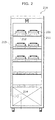
- FIG. 2 is a front elevational view of a purge apparatus with a nozzle.
- the purge apparatus 210 can purge the inside of the container 200 by discharging clean gas from the nozzle 100 corresponding to the container 200, when the container 200 is placed.
- the purge apparatus 210 is a rack-shaped apparatus including the shelf plates 211 on which multiple containers 200 can be placed.
- the purge apparatus 210 is provided with discharge units 212 with the nozzles 100 inside the shelf plates 211 corresponding to the positions where the containers 200 are placed.
- Each discharge unit 212 is connected to the pipe 213 to which the gas is guided.
- the pipe 213 is attached to a main valve 214 which roughly adjusts the flow rate of gas to be supplied to each discharge unit 212.
- the discharge unit 212 can detect whether or not the container 200 is placed on a predetermined position on the shelf plate 211, and can discharge the gas from the nozzle 100 when the container 200 is detected.
- FIG. 3 is a cross-sectional view schematically showing a connecting part of the purge apparatus composed of the nozzle and the container.
- a slight gap is formed between the nozzle 100 and the container 200 when the nozzle 100 and the container 200 are connected.
- the gap is formed by the container 200 and the shelf plate 211 contacting each other.
- the container 200 includes a guide 201 which is tapered in shape, at a part where the gas discharged from the sub-opening 102 hits.
- the guide 201 can guide the gas discharged from the sub-opening 102 in a direction of the gas discharged from the main opening 101, and functions like a reflector which reflects the gas discharged from the sub-opening 102 towards the gas discharged from the main opening 101. With this structure, most of the gas discharged from the sub-opening 102 is introduced into the container 200 together with the gas discharged from the main opening 101, while pressing the gas discharged from the main opening 101.
- the discharge unit 212 detects that the container 200 is placed, and causes the gas at the first flow rate to be discharged from the main opening 101 of the nozzle 100.
- the gas flowing in the main opening 101 is introduced into the sub-opening 102 via the through-hole 103, and is discharged from the sub-opening 102 at the second flow rate.
- the gas discharged from the sub-opening 102 forms a thin layer of gas flow surrounding the main opening 101.
- the layer of gas flow is formed in the gap between the nozzle 100 and the container 200, and exists as if to seal the gap between the nozzle 100 and the container 200. This prevents the leak of the gas discharged from the main opening 101 from the gap between the nozzle 100 and the container 200, and most of the gas is introduced into the container 200.
- the part of the gas discharged from the sub-opening 102 leaks from the gap between the nozzle 100 and the container 200; however, the second flow rate discharged from the sub-opening 102 is smaller than the first flow rate discharged from the main opening 101. Accordingly, it is possible to prevent the amount of leak as a whole, which allows efficient introduction of the gas into the container even when there is a gap between the nozzle 100 and the container 200.
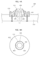
- FIG. 4A is a cross-sectional view of a nozzle which is another embodiment of the present invention
- FIG. 4B is a top view of the nozzle which is an embodiment of the present invention.
- the nozzle 100 includes a main opening 101, a sub opening 102, a through-hole 103, a main tube 111, and a sub tube 112.
- the external form of the main tube 111 has a circular truncated cone-shape, and the main opening 101 is provided along the central axis of the main tube 111.
- the sub-tube 112 is a tube-shaped member including a circular truncated cone-shaped hole corresponding to the external form of the main tube 111. Furthermore, the gap formed between the sub-tube 112 and the main tube 111 functions as the sub-opening 102.
- the sub-opening 102 has a tapered shape where the tip comes closer to the main opening 101 such that the sub-opening 102 can discharge the gas toward the main opening 101. More specifically, the sub-opening 102 has a shape where the diameter gradually decreases towards the tip.
- the abovementioned shape of the sub-opening 102 suppresses the amount of gas discharged from the sub-opening 102 from leaking through the gap between the nozzle 100 and the container 200. Therefore, it is possible to introduce the gas into the container 200 more efficiently as a whole.
- the gas is gas used for purging the container 200, and the type of gas is not particularly limited.
- the container 200 to be purged is a container 200 for holding the reticles
- clean, dry air is suitable for the gas to be used. This is because the reticles have the small risk of oxidation caused by air.
- inert gas such as nitrogen is suitable for the gas to be used. This is because the wafers have a high risk of oxidization.
- the clean gas refers to gas which has zero or small number of particles per unit volume in the gas.
- the gas may be gas such as air where several types of gasses are mixed, and may also be gas composed of a single type of gas.
- opening referred to as the main opening 101 and the sub-opening 102 in Claims and the specification is a part which determines the direction of the gas being discharged.
- the term “opening” is used in a three-dimensional concept, not in a two-dimensional concept. Accordingly, the description "the opening has a taper-shape” indicates the three-dimensional circular space, whose diameter gradually decreases, and the main tube 111 and the sub-tube 112 forming the circular space.
- the present invention is applicable to a nozzle which introduces clean gas to a container for storing the objects that needs to avoid the contamination by the particles, such as the reticles, the wafers, and the glass substrates for display apparatuses.
Landscapes
- Container, Conveyance, Adherence, Positioning, Of Wafer (AREA)
- Nozzles (AREA)
- Containers And Packaging Bodies Having A Special Means To Remove Contents (AREA)
- Manipulator (AREA)
- Cleaning Or Drying Semiconductors (AREA)
Applications Claiming Priority (1)
| Application Number | Priority Date | Filing Date | Title |
|---|---|---|---|
| JP2008207392A JP2010045138A (ja) | 2008-08-11 | 2008-08-11 | ノズル |
Publications (3)
| Publication Number | Publication Date |
|---|---|
| EP2154716A2 true EP2154716A2 (de) | 2010-02-17 |
| EP2154716A3 EP2154716A3 (de) | 2010-03-24 |
| EP2154716B1 EP2154716B1 (de) | 2017-01-04 |
Family
ID=41268436
Family Applications (1)
| Application Number | Title | Priority Date | Filing Date |
|---|---|---|---|
| EP09167523.1A Not-in-force EP2154716B1 (de) | 2008-08-11 | 2009-08-10 | Düse |
Country Status (6)
| Country | Link |
|---|---|
| US (1) | US8408253B2 (de) |
| EP (1) | EP2154716B1 (de) |
| JP (1) | JP2010045138A (de) |
| KR (1) | KR101358258B1 (de) |
| SG (2) | SG159456A1 (de) |
| TW (1) | TWI454317B (de) |
Families Citing this family (2)
| Publication number | Priority date | Publication date | Assignee | Title |
|---|---|---|---|---|
| JP5887719B2 (ja) * | 2011-05-31 | 2016-03-16 | シンフォニアテクノロジー株式会社 | パージ装置、ロードポート、ボトムパージノズル本体、ボトムパージユニット |
| CN115621212B (zh) * | 2022-11-07 | 2023-04-07 | 合肥矽迈微电子科技有限公司 | 一种防溢的封装结构及其装片方法 |
Citations (2)
| Publication number | Priority date | Publication date | Assignee | Title |
|---|---|---|---|---|
| JP2001031212A (ja) | 1999-07-22 | 2001-02-06 | Murata Mach Ltd | 自動倉庫 |
| JP2008207392A (ja) | 2007-02-23 | 2008-09-11 | Hitachi High-Tech Instruments Co Ltd | スクリーン印刷機 |
Family Cites Families (14)
| Publication number | Priority date | Publication date | Assignee | Title |
|---|---|---|---|---|
| EP0954366A4 (de) * | 1996-12-31 | 2001-06-20 | Atmi Ecosys Corp | Einlassstruktur zum einbringen eines teilchenförmigen feststoffhaltigen und/oder feststoffformenden gasstroms in ein gasbehandlungssystem |
| DE29712026U1 (de) * | 1997-07-09 | 1998-11-12 | EBARA Germany GmbH, 63452 Hanau | Brenner für die Verbrennung von Abgasen mit mindestens einer kondensationsfähigen Komponente |
| SG106599A1 (en) * | 2000-02-01 | 2004-10-29 | Tokyo Electron Ltd | Substrate processing apparatus and substrate processing method |
| US6669103B2 (en) * | 2001-08-30 | 2003-12-30 | Shirley Cheng Tsai | Multiple horn atomizer with high frequency capability |
| JP4074814B2 (ja) * | 2002-01-30 | 2008-04-16 | 大日本スクリーン製造株式会社 | 基板処理装置および基板処理方法 |
| JP2003257845A (ja) | 2002-03-07 | 2003-09-12 | Canon Inc | 露光装置 |
| US20040043140A1 (en) * | 2002-08-21 | 2004-03-04 | Ramesh Jagannathan | Solid state lighting using compressed fluid coatings |
| KR100578138B1 (ko) * | 2003-11-03 | 2006-05-10 | 삼성전자주식회사 | 플라즈마 처리 장치에 사용되는 분사관 및 이를 가지는 플라즈마 화학 기상 증착 장치 |
| JP2005167168A (ja) | 2003-12-02 | 2005-06-23 | Dan-Takuma Technologies Inc | パージバルブおよび保管装置 |
| JP4451175B2 (ja) * | 2004-03-19 | 2010-04-14 | 大日本スクリーン製造株式会社 | ノズル洗浄装置および基板処理装置 |
| KR20040101948A (ko) * | 2004-05-31 | 2004-12-03 | (주)케이.씨.텍 | 표면세정용 승화성 고체입자 분사용 노즐 및 이를 이용한 세정방법 |
| TWI267405B (en) * | 2004-07-20 | 2006-12-01 | Sez Ag | Fluid discharging device |
| JP4278676B2 (ja) * | 2005-11-30 | 2009-06-17 | Tdk株式会社 | 密閉容器の蓋開閉システム |
| JP2008108829A (ja) * | 2006-10-24 | 2008-05-08 | Dainippon Screen Mfg Co Ltd | 二流体ノズルおよびそれを用いた基板処理装置 |
-
2008
- 2008-08-11 JP JP2008207392A patent/JP2010045138A/ja active Pending
-
2009
- 2009-02-02 KR KR1020090008052A patent/KR101358258B1/ko not_active Expired - Fee Related
- 2009-04-28 TW TW098114036A patent/TWI454317B/zh not_active IP Right Cessation
- 2009-08-06 SG SG200905267-1A patent/SG159456A1/en unknown
- 2009-08-06 SG SG2012007977A patent/SG178750A1/en unknown
- 2009-08-10 EP EP09167523.1A patent/EP2154716B1/de not_active Not-in-force
- 2009-08-10 US US12/538,490 patent/US8408253B2/en active Active
Patent Citations (2)
| Publication number | Priority date | Publication date | Assignee | Title |
|---|---|---|---|---|
| JP2001031212A (ja) | 1999-07-22 | 2001-02-06 | Murata Mach Ltd | 自動倉庫 |
| JP2008207392A (ja) | 2007-02-23 | 2008-09-11 | Hitachi High-Tech Instruments Co Ltd | スクリーン印刷機 |
Also Published As
| Publication number | Publication date |
|---|---|
| EP2154716B1 (de) | 2017-01-04 |
| TW201006558A (en) | 2010-02-16 |
| KR20100019938A (ko) | 2010-02-19 |
| SG159456A1 (en) | 2010-03-30 |
| US20100032050A1 (en) | 2010-02-11 |
| JP2010045138A (ja) | 2010-02-25 |
| SG178750A1 (en) | 2012-03-29 |
| TWI454317B (zh) | 2014-10-01 |
| KR101358258B1 (ko) | 2014-02-05 |
| EP2154716A3 (de) | 2010-03-24 |
| US8408253B2 (en) | 2013-04-02 |
Similar Documents
| Publication | Publication Date | Title |
|---|---|---|
| KR102106199B1 (ko) | 기판 처리 장치 | |
| JP2010016199A (ja) | パージ装置 | |
| US10964556B2 (en) | Substrate processing apparatus, substrate processing system, and substrate processing method | |
| US8083456B2 (en) | Contained object transfer system | |
| JP5712902B2 (ja) | 基板処理装置、基板処理方法及び記憶媒体 | |
| KR20200044753A (ko) | 기판 처리 장치 | |
| TWI278057B (en) | Enclosed container lid opening/closing system and enclosed container lid opening/closing method | |
| JP6492884B2 (ja) | ロードポート装置 | |
| US20060290151A1 (en) | Non-contact holder device and non-contact holding and conveying device | |
| US20150243538A1 (en) | Pod and purge system using the same | |
| TWI690990B (zh) | 基板處理方法及基板處理裝置 | |
| TW201705341A (zh) | 晶圓儲存容器 | |
| KR102378913B1 (ko) | 기판 처리 방법 및 기판 처리 장치 | |
| EP2154716B1 (de) | Düse | |
| JP4359885B2 (ja) | ベルヌーイチャック | |
| JP3964361B2 (ja) | パージ装置およびパージ方法 | |
| WO2004097927A1 (ja) | パージ装置およびパージ方法 | |
| US20200312697A1 (en) | Substrate processing device, substrate processing method, and semiconductor manufacturing method | |
| JP2011061156A (ja) | 基板処理装置、ガス導入装置、及び半導体装置の製造方法 | |
| CN111417593B (zh) | 用于对具有注入开口的容器进行充气和封闭的封闭装置 | |
| JP2007273697A (ja) | 基板搬送容器および基板搬送容器内空間のガス置換方法 | |
| JP2012074471A (ja) | ポットおよびこのポットを備えた基板処理装置 | |
| JP2005340521A (ja) | ベルヌーイチャック | |
| KR20070081833A (ko) | 기판 처리 설비 | |
| JP2006168984A (ja) | 蛍光管投入ホッパー |
Legal Events
| Date | Code | Title | Description |
|---|---|---|---|
| PUAI | Public reference made under article 153(3) epc to a published international application that has entered the european phase |
Free format text: ORIGINAL CODE: 0009012 |
|
| AK | Designated contracting states |
Kind code of ref document: A2 Designated state(s): AT BE BG CH CY CZ DE DK EE ES FI FR GB GR HR HU IE IS IT LI LT LU LV MC MK MT NL NO PL PT RO SE SI SK SM TR |
|
| PUAL | Search report despatched |
Free format text: ORIGINAL CODE: 0009013 |
|
| AK | Designated contracting states |
Kind code of ref document: A3 Designated state(s): AT BE BG CH CY CZ DE DK EE ES FI FR GB GR HR HU IE IS IT LI LT LU LV MC MK MT NL NO PL PT RO SE SI SK SM TR |
|
| RIC1 | Information provided on ipc code assigned before grant |
Ipc: H01L 21/673 20060101AFI20091209BHEP Ipc: B01D 41/00 20060101ALI20100215BHEP Ipc: F23G 7/06 20060101ALI20100215BHEP |
|
| 17P | Request for examination filed |
Effective date: 20100526 |
|
| 17Q | First examination report despatched |
Effective date: 20140414 |
|
| GRAP | Despatch of communication of intention to grant a patent |
Free format text: ORIGINAL CODE: EPIDOSNIGR1 |
|
| INTG | Intention to grant announced |
Effective date: 20160805 |
|
| GRAS | Grant fee paid |
Free format text: ORIGINAL CODE: EPIDOSNIGR3 |
|
| GRAA | (expected) grant |
Free format text: ORIGINAL CODE: 0009210 |
|
| AK | Designated contracting states |
Kind code of ref document: B1 Designated state(s): AT BE BG CH CY CZ DE DK EE ES FI FR GB GR HR HU IE IS IT LI LT LU LV MC MK MT NL NO PL PT RO SE SI SK SM TR |
|
| REG | Reference to a national code |
Ref country code: GB Ref legal event code: FG4D |
|
| REG | Reference to a national code |
Ref country code: CH Ref legal event code: EP |
|
| REG | Reference to a national code |
Ref country code: AT Ref legal event code: REF Ref document number: 859993 Country of ref document: AT Kind code of ref document: T Effective date: 20170115 |
|
| REG | Reference to a national code |
Ref country code: IE Ref legal event code: FG4D |
|
| REG | Reference to a national code |
Ref country code: DE Ref legal event code: R096 Ref document number: 602009043471 Country of ref document: DE |
|
| REG | Reference to a national code |
Ref country code: LT Ref legal event code: MG4D Ref country code: NL Ref legal event code: MP Effective date: 20170104 |
|
| REG | Reference to a national code |
Ref country code: AT Ref legal event code: MK05 Ref document number: 859993 Country of ref document: AT Kind code of ref document: T Effective date: 20170104 |
|
| PG25 | Lapsed in a contracting state [announced via postgrant information from national office to epo] |
Ref country code: NL Free format text: LAPSE BECAUSE OF FAILURE TO SUBMIT A TRANSLATION OF THE DESCRIPTION OR TO PAY THE FEE WITHIN THE PRESCRIBED TIME-LIMIT Effective date: 20170104 |
|
| PG25 | Lapsed in a contracting state [announced via postgrant information from national office to epo] |
Ref country code: IS Free format text: LAPSE BECAUSE OF FAILURE TO SUBMIT A TRANSLATION OF THE DESCRIPTION OR TO PAY THE FEE WITHIN THE PRESCRIBED TIME-LIMIT Effective date: 20170504 Ref country code: LT Free format text: LAPSE BECAUSE OF FAILURE TO SUBMIT A TRANSLATION OF THE DESCRIPTION OR TO PAY THE FEE WITHIN THE PRESCRIBED TIME-LIMIT Effective date: 20170104 Ref country code: FI Free format text: LAPSE BECAUSE OF FAILURE TO SUBMIT A TRANSLATION OF THE DESCRIPTION OR TO PAY THE FEE WITHIN THE PRESCRIBED TIME-LIMIT Effective date: 20170104 Ref country code: GR Free format text: LAPSE BECAUSE OF FAILURE TO SUBMIT A TRANSLATION OF THE DESCRIPTION OR TO PAY THE FEE WITHIN THE PRESCRIBED TIME-LIMIT Effective date: 20170405 Ref country code: HR Free format text: LAPSE BECAUSE OF FAILURE TO SUBMIT A TRANSLATION OF THE DESCRIPTION OR TO PAY THE FEE WITHIN THE PRESCRIBED TIME-LIMIT Effective date: 20170104 Ref country code: NO Free format text: LAPSE BECAUSE OF FAILURE TO SUBMIT A TRANSLATION OF THE DESCRIPTION OR TO PAY THE FEE WITHIN THE PRESCRIBED TIME-LIMIT Effective date: 20170404 |
|
| PG25 | Lapsed in a contracting state [announced via postgrant information from national office to epo] |
Ref country code: SE Free format text: LAPSE BECAUSE OF FAILURE TO SUBMIT A TRANSLATION OF THE DESCRIPTION OR TO PAY THE FEE WITHIN THE PRESCRIBED TIME-LIMIT Effective date: 20170104 Ref country code: BG Free format text: LAPSE BECAUSE OF FAILURE TO SUBMIT A TRANSLATION OF THE DESCRIPTION OR TO PAY THE FEE WITHIN THE PRESCRIBED TIME-LIMIT Effective date: 20170404 Ref country code: LV Free format text: LAPSE BECAUSE OF FAILURE TO SUBMIT A TRANSLATION OF THE DESCRIPTION OR TO PAY THE FEE WITHIN THE PRESCRIBED TIME-LIMIT Effective date: 20170104 Ref country code: AT Free format text: LAPSE BECAUSE OF FAILURE TO SUBMIT A TRANSLATION OF THE DESCRIPTION OR TO PAY THE FEE WITHIN THE PRESCRIBED TIME-LIMIT Effective date: 20170104 Ref country code: ES Free format text: LAPSE BECAUSE OF FAILURE TO SUBMIT A TRANSLATION OF THE DESCRIPTION OR TO PAY THE FEE WITHIN THE PRESCRIBED TIME-LIMIT Effective date: 20170104 Ref country code: PT Free format text: LAPSE BECAUSE OF FAILURE TO SUBMIT A TRANSLATION OF THE DESCRIPTION OR TO PAY THE FEE WITHIN THE PRESCRIBED TIME-LIMIT Effective date: 20170504 Ref country code: PL Free format text: LAPSE BECAUSE OF FAILURE TO SUBMIT A TRANSLATION OF THE DESCRIPTION OR TO PAY THE FEE WITHIN THE PRESCRIBED TIME-LIMIT Effective date: 20170104 |
|
| REG | Reference to a national code |
Ref country code: DE Ref legal event code: R097 Ref document number: 602009043471 Country of ref document: DE |
|
| PG25 | Lapsed in a contracting state [announced via postgrant information from national office to epo] |
Ref country code: IT Free format text: LAPSE BECAUSE OF FAILURE TO SUBMIT A TRANSLATION OF THE DESCRIPTION OR TO PAY THE FEE WITHIN THE PRESCRIBED TIME-LIMIT Effective date: 20170104 Ref country code: EE Free format text: LAPSE BECAUSE OF FAILURE TO SUBMIT A TRANSLATION OF THE DESCRIPTION OR TO PAY THE FEE WITHIN THE PRESCRIBED TIME-LIMIT Effective date: 20170104 Ref country code: SK Free format text: LAPSE BECAUSE OF FAILURE TO SUBMIT A TRANSLATION OF THE DESCRIPTION OR TO PAY THE FEE WITHIN THE PRESCRIBED TIME-LIMIT Effective date: 20170104 Ref country code: CZ Free format text: LAPSE BECAUSE OF FAILURE TO SUBMIT A TRANSLATION OF THE DESCRIPTION OR TO PAY THE FEE WITHIN THE PRESCRIBED TIME-LIMIT Effective date: 20170104 Ref country code: RO Free format text: LAPSE BECAUSE OF FAILURE TO SUBMIT A TRANSLATION OF THE DESCRIPTION OR TO PAY THE FEE WITHIN THE PRESCRIBED TIME-LIMIT Effective date: 20170104 |
|
| PGFP | Annual fee paid to national office [announced via postgrant information from national office to epo] |
Ref country code: DE Payment date: 20170822 Year of fee payment: 9 |
|
| PLBE | No opposition filed within time limit |
Free format text: ORIGINAL CODE: 0009261 |
|
| STAA | Information on the status of an ep patent application or granted ep patent |
Free format text: STATUS: NO OPPOSITION FILED WITHIN TIME LIMIT |
|
| PG25 | Lapsed in a contracting state [announced via postgrant information from national office to epo] |
Ref country code: SM Free format text: LAPSE BECAUSE OF FAILURE TO SUBMIT A TRANSLATION OF THE DESCRIPTION OR TO PAY THE FEE WITHIN THE PRESCRIBED TIME-LIMIT Effective date: 20170104 Ref country code: DK Free format text: LAPSE BECAUSE OF FAILURE TO SUBMIT A TRANSLATION OF THE DESCRIPTION OR TO PAY THE FEE WITHIN THE PRESCRIBED TIME-LIMIT Effective date: 20170104 |
|
| 26N | No opposition filed |
Effective date: 20171005 |
|
| PG25 | Lapsed in a contracting state [announced via postgrant information from national office to epo] |
Ref country code: SI Free format text: LAPSE BECAUSE OF FAILURE TO SUBMIT A TRANSLATION OF THE DESCRIPTION OR TO PAY THE FEE WITHIN THE PRESCRIBED TIME-LIMIT Effective date: 20170104 |
|
| REG | Reference to a national code |
Ref country code: CH Ref legal event code: PL |
|
| PG25 | Lapsed in a contracting state [announced via postgrant information from national office to epo] |
Ref country code: MC Free format text: LAPSE BECAUSE OF FAILURE TO SUBMIT A TRANSLATION OF THE DESCRIPTION OR TO PAY THE FEE WITHIN THE PRESCRIBED TIME-LIMIT Effective date: 20170104 |
|
| GBPC | Gb: european patent ceased through non-payment of renewal fee |
Effective date: 20170810 |
|
| PG25 | Lapsed in a contracting state [announced via postgrant information from national office to epo] |
Ref country code: CH Free format text: LAPSE BECAUSE OF NON-PAYMENT OF DUE FEES Effective date: 20170831 Ref country code: LI Free format text: LAPSE BECAUSE OF NON-PAYMENT OF DUE FEES Effective date: 20170831 |
|
| REG | Reference to a national code |
Ref country code: BE Ref legal event code: MM Effective date: 20170831 |
|
| REG | Reference to a national code |
Ref country code: FR Ref legal event code: ST Effective date: 20180430 |
|
| REG | Reference to a national code |
Ref country code: IE Ref legal event code: MM4A |
|
| PG25 | Lapsed in a contracting state [announced via postgrant information from national office to epo] |
Ref country code: LU Free format text: LAPSE BECAUSE OF NON-PAYMENT OF DUE FEES Effective date: 20170810 |
|
| PG25 | Lapsed in a contracting state [announced via postgrant information from national office to epo] |
Ref country code: IE Free format text: LAPSE BECAUSE OF NON-PAYMENT OF DUE FEES Effective date: 20170810 Ref country code: GB Free format text: LAPSE BECAUSE OF NON-PAYMENT OF DUE FEES Effective date: 20170810 |
|
| PG25 | Lapsed in a contracting state [announced via postgrant information from national office to epo] |
Ref country code: BE Free format text: LAPSE BECAUSE OF NON-PAYMENT OF DUE FEES Effective date: 20170831 Ref country code: FR Free format text: LAPSE BECAUSE OF NON-PAYMENT OF DUE FEES Effective date: 20170831 |
|
| PG25 | Lapsed in a contracting state [announced via postgrant information from national office to epo] |
Ref country code: MT Free format text: LAPSE BECAUSE OF NON-PAYMENT OF DUE FEES Effective date: 20170810 |
|
| REG | Reference to a national code |
Ref country code: DE Ref legal event code: R119 Ref document number: 602009043471 Country of ref document: DE |
|
| PG25 | Lapsed in a contracting state [announced via postgrant information from national office to epo] |
Ref country code: HU Free format text: LAPSE BECAUSE OF FAILURE TO SUBMIT A TRANSLATION OF THE DESCRIPTION OR TO PAY THE FEE WITHIN THE PRESCRIBED TIME-LIMIT; INVALID AB INITIO Effective date: 20090810 |
|
| PG25 | Lapsed in a contracting state [announced via postgrant information from national office to epo] |
Ref country code: DE Free format text: LAPSE BECAUSE OF NON-PAYMENT OF DUE FEES Effective date: 20190301 |
|
| PG25 | Lapsed in a contracting state [announced via postgrant information from national office to epo] |
Ref country code: CY Free format text: LAPSE BECAUSE OF NON-PAYMENT OF DUE FEES Effective date: 20170104 |
|
| PG25 | Lapsed in a contracting state [announced via postgrant information from national office to epo] |
Ref country code: MK Free format text: LAPSE BECAUSE OF FAILURE TO SUBMIT A TRANSLATION OF THE DESCRIPTION OR TO PAY THE FEE WITHIN THE PRESCRIBED TIME-LIMIT Effective date: 20170104 |
|
| PG25 | Lapsed in a contracting state [announced via postgrant information from national office to epo] |
Ref country code: TR Free format text: LAPSE BECAUSE OF FAILURE TO SUBMIT A TRANSLATION OF THE DESCRIPTION OR TO PAY THE FEE WITHIN THE PRESCRIBED TIME-LIMIT Effective date: 20170104 |