EP2153752B1 - Rückenlehne - Google Patents
Rückenlehne Download PDFInfo
- Publication number
- EP2153752B1 EP2153752B1 EP20090009853 EP09009853A EP2153752B1 EP 2153752 B1 EP2153752 B1 EP 2153752B1 EP 20090009853 EP20090009853 EP 20090009853 EP 09009853 A EP09009853 A EP 09009853A EP 2153752 B1 EP2153752 B1 EP 2153752B1
- Authority
- EP
- European Patent Office
- Prior art keywords
- backrest
- support
- armchair according
- chair
- seat
- Prior art date
- Legal status (The legal status is an assumption and is not a legal conclusion. Google has not performed a legal analysis and makes no representation as to the accuracy of the status listed.)
- Not-in-force
Links
Images


Classifications
-
- A—HUMAN NECESSITIES
- A47—FURNITURE; DOMESTIC ARTICLES OR APPLIANCES; COFFEE MILLS; SPICE MILLS; SUCTION CLEANERS IN GENERAL
- A47C—CHAIRS; SOFAS; BEDS
- A47C3/00—Chairs characterised by structural features; Chairs or stools with rotatable or vertically-adjustable seats
- A47C3/02—Rocking chairs
- A47C3/021—Rocking chairs having elastic frames
- A47C3/023—Rocking chairs having elastic frames made of tubular material
-
- A—HUMAN NECESSITIES
- A47—FURNITURE; DOMESTIC ARTICLES OR APPLIANCES; COFFEE MILLS; SPICE MILLS; SUCTION CLEANERS IN GENERAL
- A47C—CHAIRS; SOFAS; BEDS
- A47C7/00—Parts, details, or accessories of chairs or stools
- A47C7/36—Supports for the head or the back
- A47C7/40—Supports for the head or the back for the back
- A47C7/46—Supports for the head or the back for the back with special, e.g. adjustable, lumbar region support profile; "Ackerblom" profile chairs
Definitions
- the invention relates to an armchair with seat and backrest, wherein the backrest has a backrest support and a backrest plate.
- Tilting backrests which support the back perfectly even with a slight recline, are known in office chairs.
- tilting backrests are hung on a complex mechanism below the seat and are expensive. Since chairs as a design object are also subject to design requirements, such chunky suspensions are often undesirable.
- the backrest is attached to the two armrests suspended.
- Such a free-hanging backrest is not attached to the seat and relatively short, so that it supports only the middle area of the back - lordosis and pelvic area are free and not supported.
- Known free-hanging backrests that extend into the pelvic area are rigid.
- the object of the invention is to provide an armchair of the type mentioned, in which the backrest optimally supports the middle region of the back of a person sitting on the chair up to the pelvic area. Also, this support should always be guaranteed with slight reclines or rockers.
- the armchair should be inexpensive to produce and act aesthetically pleasing by a free-hanging backrest.
- this object is achieved with an armchair of the type mentioned above in that the backrest support has two armrest sections and a center section bent upward at an angle such that the backrest plate is fastened in its upper region to the middle section of the backrest support and with a lower backrest Range freely reaches close to the seat that the backrest support is flexible and can be deformed when leaning by a person sitting on the chair by increasing the angle between its armrest sections and its middle section, and that the backrest plate is flexible and its upper section can move with the central portion of the backrest support when its lower portion rests against the pelvis of the person sitting on the chair.
- backrest support and backrest plate allows a suspension of the backrest to the armrests and thus allows more creative freedom.
- a rocking and easy reclining allows without a person sitting on the chair through the lower part of the Backrest is pushed forward from the seat, as would be the case with a rigid backrest. It only creates a barely noticeable pressure of the lower portion of the backrest plate on the pelvic area of the person.
- the backrest is always on the back and supports it in the lumbar area.
- the backrest support is so flexible that it is increased by at least 4 degrees at a backrest force of 400 N, which is 40 cm above the seat centered in the backrest plate, the angle between the Armlehnabroughen and the middle section.
- the backrest plate is so flexible that when the angle between the armrest sections and the center section is increased by 5 degrees in the lower section, it pushes 10 cm above the seat with no more than 20 N on the pelvis of the person sitting on the chair.
- the armchair is a cantilever chair.
- the inventive armchair may comprise a tubular frame to which the seat may be attached.
- the end portions of the tubular frame can be pulled up in the front of the chair to the height of the armrests and be connected to the armrest sections of the backrest support to shock.
- the backrest support of the inventive armchair can be a one-piece plastic injection molded part, which can be produced inexpensively.
- the backrest plate preferably has a padded with a flexible support member, which may also be a cost-producible one-piece plastic injection molded part.
- This support member may have two lateral, strip-shaped spars and extending between them, rotatable about this longitudinal direction slats.
- the lamellae can branch out against the lateral uprights to form narrower joint sections, whereby adjacent joint sections of adjacent lamellae unite against the lateral uprights to form wider connection sections.
- the lateral spars and the slats can be flexible with respect to their longitudinal extent.
- Such a structure of the support element guarantees a high flexibility of the backrest plate, which can be optimally adapted to the back of the person sitting on the chair.
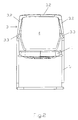
- Fig. 1 the preferred embodiment of the armchair is shown in a side view.
- the armchair is a cantilever and includes a seat 1 which is fixed to a tubular frame such that the seat is free at the rear.
- the end sections 5.1 of the tubular frame 5 are raised in the front region of the chair to the height of the armrests and connected to armrest sections 3.1 of the backrest support 3 to shock.
- the end sections 5.1 of the tubular frame 5 and the armrest sections 3.1 extend approximately horizontally.
- the two armrest sections 3.1 are connected via a center section 3.2, which is opposite to the armrest sections 3.1 bent at an angle upwards.
- the backrest support 3 is a one-piece plastic injection-molded part, which is flexible in connecting areas 3.3 between the armrest sections 3.1 and the middle section 3.2, so that the backrest support 3 when leaning by a person sitting on the chair by increasing the angle between its armrest sections 3.1 and its middle section 3.2 can deform.
- the movements of the back are further down and in Fig. 3 described in more detail.
- a backrest plate 4 is fastened in its upper region 4.1 to the middle section 3.2 of the backrest support 3.
- the lower portion of the backrest plate 4.1 extends freely to close to the seat 1. There is no connection between the seat 1 and backrest plate. 4
- Fig. 2 the preferred form of the armchair is shown in a rear view. It can be seen that the middle section 3.2 of the backrest support 3 pulls up on both sides of the backrest plate 4 from the connection region 3.3 and converges at the upper edge of the backrest plate 4. The center section 3.2 thus runs bow-shaped along the edge of the upper region of the backrest plate 4. Seat 1 and tube frame 5 are also shown.
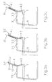
- Fig. 3 shows a schematic representation of the deformation of the backrest when sitting a person ( Fig. 3b ) and in reclining the same person ( Fig. 3c ).
- Fig. 3a is the unloaded state of the armchair with seat 1, tube frame 5, backrest support with armrest section 3.1 and center section 3.2, and back plate 4 with its upper 4.1 and lower section 4.2.
- the seat 1 is firmly connected to the tubular frame 5.
- the backrest plate is in the upper region 4.1 at the points 11, 12 shown by arrows, on both sides firmly connected to the middle section 3.2. In the lower area 4.2 the backrest plate hangs free.
- Fig. 3b is the movement of the back plate and the backrest support 3 with respect to the unloaded state of Fig. 3a shown.
- the dashed line shows the position in the unloaded state.
- the upper region of the backrest plate 4.1 together with the middle section 3.2 inclines slightly backwards and the lower region of the backrest plate 4.2 is pressed slightly forward, so that the backrest plate of Person 10 is in the pelvic area.
- the armrest section 3.1 of the backrest support 3 remains unchanged.
- Fig. 3c shows the movement of the backrest plate and the backrest support with additional load and with respect to the state of 3b , in which the backrest plate is only slightly loaded, as is the case when sitting.
- the dashed line shows the position of the backrest plate and the backrest support in slightly loaded condition.
- backrest plate and backrest support are additionally deformed.
- the angle between the armrest sections 3.1 and the middle section 3.2 increases.
- the middle section tilts further back together with the upper region of the backrest plate 4.1.
- the lower region of the backrest plate 4.2 remains in the position that has set when sitting of the person 10. This effect is achieved by the high flexibility of the backrest plate, thus creating only a slight pressure on the pelvic area of the person.
- the deformation of the backrest plate prevents the pushing out of the person 10 from the seat 1, as would be the case with inflexible back plates.
- the backrest force which is introduced 40 cm above the seat 1 in the backrest plate 4, when reclining up to 400 N.
- the angle between the armrest sections 3.1 and the middle section 3.2 increases by the flexibility of the backrest support 3 preferably by at least 4 degrees with respect to the unloaded state.
- With an enlargement of the angle between the Armlehnabêten 3.1 and the middle section 3.2 by 5 degrees arises in the lower section 4.2 of the flexible backrest plate 4 10 cm above the seat 1, a force on the pelvic area of the person 10 of preferably less than 20 N.
- the majority of introduced Lehnenkraft goes into the deformation of the backrest support 3 and the backrest plate 4 on.
- the backrest plate 4 comprises a flexible support element and a padding.
- Fig. 4 shows this support member 7 in a front view.
- the support element 7 is a one-piece plastic injection-molded part and comprises two lateral, strip-shaped spars 7.1. Between the two bars 7.1 extend slats 7.2, which are around this Longitudinal extent are rotatable. The slats 7.2 branch out against the lateral spars 7.1 out to form narrower joint sections 7.3. Adjacent joint sections 7.3 of adjacent lamellae 7.2 unite against the lateral rails 7.1 towards wider connecting sections 7.4. By this training, even with local loads, a distributed deformation of the backrest always incorporating several slats 7.2 is achieved.
- the lateral bars 7.1 and the slats 7.2 are flexible with respect to their longitudinal extension to ensure optimum adaptation to the back of the person sitting on the chair, as it is already above and in Fig. 3 is described.
- Fig. 5 shows the inventive support element 7 in a side view.
- the support element 7 is preformed, so that it bulges out in the lumbar region 7.5.
- the lordosis of a person sitting on the chair is optimally supported.
Landscapes
- Chair Legs, Seat Parts, And Backrests (AREA)
Description
- Die Erfindung betrifft einen Armlehnstuhl mit Sitz und Rückenlehne, wobei die Rückenlehne einen Lehnenträger und eine Lehnenplatte aufweist.
- Bei Armlehnstühlen, wie sie vor allem in Konferenzsälen und Sitzungszimmern vorkommen, sind verschiedene Arten von Rückenlehnen bekannt.
- Ein solcher Armlehnenstruhl ist aus der Anmeldung
US 4 522 444 bekannt. - Zum Beispiel gibt es Armlehnstühle die aus einer einteiligen Schale von Sitz und Rückenlehne geformt sind. Solche Rückenlehnen sind auch mit Polsterung relativ unflexibel und passen sich kaum den Bewegungen einer auf dem Stuhl sitzenden Person an. Eine gewisse Bewegungsfreiheit bei leichtem Zurücklehnen oder Wippen wird bei manchen Stühlen zwar dadurch erreicht, dass die Rückenlehne im oberen Bereich aus einem flexiblen Material besteht. Jedoch wird die Lordose beim Zurücklehnen nicht mehr optimal gestützt, da sich nur der oberste Teil der Rücklehne zurückneigen kann und der Rest der Rückenlehne starr ist.
- Neigbare Rückenlehnen, die auch bei leichtem Zurücklehnen den Rücken optimal stützen, sind bei Bürostühlen bekannt. Solche neigbaren Rückenlehnen sind jedoch an einer aufwendigen Mechanik unterhalb dem Sitz aufgehängt und sind teuer. Da Stühle als Designobjekt auch Anforderungen hinsichtlich ihrer Gestaltung unterliegen, sind solche klobigen Aufhängungen häufig unerwünscht.
- Bei schlanken, einfach und kostengünstig gebauten und "leicht" wirkenden Armlehnstühlen ist die Rückenlehne zum Beispiel an den beiden Armlehnen aufgehängt. Eine solche frei hängende Rückenlehne ist nicht am Sitz befestigt und relativ kurz ausgebildet, so dass sie nur den mittleren Bereich des Rücken stützt - Lordosen- und Beckenbereich sind frei und nicht gestüzt. Bekannte freihängende Rückenlehnen die sich bis in den Beckenbereich erstrecken sind starr ausgebildet.
- Die technischen Anforderungen an Stühle, z.B. optimale Anpassung an die Rückenform auch bei leichtem Zurücklehnen, sind mit den gestalterischen Anforderungen, z.B. freihängende Rückenlehnen, nur schwer vereinbar.
- Aufgabe der Erfindung ist es, einen Armlehnstuhl der eingangs genannten Art anzugeben, bei welchem die Rückenlehne den mittleren Bereich des Rückens einer auf dem Stuhl sitzenden Person bis hin zum Beckenbereich optimal stützt. Auch soll diese Stütztung bei leichten Zurücklehnen oder Wippen stets gewährleistet sein. Der Armlehnstuhl soll kostengünstig herstellbar sein und durch eine freihängende Rückenlehne ästhetisch ansprechend wirken.
- Erfindungsgemäss wird diese Aufgabe bei einem Armlehnstuhl der eingangs genannten Art dadurch gelöst, dass der Lehnenträger zwei Armlehnenabschnitte und einen gegenüber diesen unter einem Winkel nach oben abgebogenen Mittenabschnitt aufweist, dass die Lehnenplatte in ihrem oberen Bereich an dem Mittenabschnitt des Lehnenträgers befestigt ist und mit einem unteren Bereich frei bis nahe an den Sitz heranreicht, dass der Lehnenträger flexibel ist und sich beim Anlehnen durch eine auf dem Stuhl sitzende Person unter Vergrösserung des Winkels zwischen seinen Armlehnenabschnitten und seinem Mittenabschnitt verformen kann, und dass auch die Lehnenplatte flexibel ist und sich ihr oberer Abschnitt mit dem Mittenabschnitt des Lehnenträgers bewegen kann, wenn ihr unterer Abschnitt am Becken der auf dem Stuhl sitzenden Person anliegt.
- Die erfindungsgemässe Konstruktion von Lehnenträger und Lehnenplatte ermöglicht eine Aufhängung der Rückenlehne an die Armlehnen und lässt somit weitere gestalterische Freiheiten zu. Zusätzlich wird wegen der hohen Flexibiltät des Lehnenträgers und der Lehnenplatte ein Wippen und leichtes Zurücklehnen ermöglicht, ohne dass eine auf dem Stuhl sitzende Person durch den unteren Bereich der Rückenlehne nach vorn aus dem Sitz geschoben wird, wie es bei einer starren Rückenlehne der Fall wäre. Es entsteht lediglich ein kaum spürbarer Druck des unteren Bereiches der Lehnenplatte auf den Beckenbereich der Person. Die Rückenlehne liegt dabei immer am Rücken an und stützt diesen auch im Lordosenbereich.
- In einer bevorzugten Ausführungsform ist der Lehnenträger so flexibel, dass er bei einer Lehnenkraft von 400 N, welche 40 cm über dem Sitz mittig in die Lehnenplatte eingeleitet wird, der Winkel zwischen den Armlehnabschnitten und dem Mittenabschnitt um wenigstens 4 Grad vergrössert ist. Die Lehnenplatte ist so flexibel, dass sie bei einer Vergrösserung des Winkels zwischen den Armlehnabschnitten und dem Mittenabschnitt um 5 Grad im unteren Abschnitt 10 cm über dem Sitz mit nicht mehr als 20 N auf das Becken der auf dem Stuhl sitzenden Person drückt.
- In einer weiteren Ausführungsform ist der Armlehnstuhl ein Freischwinger.
- Der erfinderische Armlehnstuhl kann ein Rohrgestell aufweisen, an welchem der Sitz befestigt sein kann. Die Endabschnitte des Rohrgestells könne im vorderen Bereich des Stuhls bis auf die Höhe der Armlehnen hochgezogen sein und mit den Armlehnenabschnitten des Lehnenträgers auf Stoss verbunden sein. Der Lehnenträger des erfinderischen Armlehnstuhles kann ein einstückiges Kunststoff-Spritzgussteil sein, welches sich kostengünstig herstellen lässt.
- Die Lehnenplatte weist vorzugsweise ein mit einer Polsterung versehenes flexibles Stützelement auf, welches ebenfalls ein kostengünstig herstellbares einstückiges Kunststoff-Spritzgussteil sein kann. Dieses Stützelement kann zwei seitliche, leistenförmige Holme und sich zwischen diesen erstreckende, um diese Längserstreckung drehbare Lamellen aufweisen. Die Lamellen können sich gegen die seitlichen Holme hin unter Ausbildung von schmaleren Gelenkabschnitten verzweigen, wobei sich benachbarte Gelenkabschnitte von benachbarten Lamellen gegen die seitlichen Holme hin unter Ausbildung von breiteren Verbindungsabschnitten vereinen. Die seitlichen Holme sowie die Lamellen können bezüglich ihrer Längserstreckung flexibel sein.
- Eine solche Struktur des Stützelementes garantiert eine hohe Flexibiltät der Lehnenplatte, welche sich so optimal dem Rücken der auf dem Stuhl sitzenden Person anpassen kann.
- Die Erfindung soll nachfolgend anhand von Ausführungsbeispielen im Zusammenhang mit der Zeichnung näher erläutert werden. Es zeigen:
- Fig. 1
- eine Seitenansicht der bevorzugten Ausführungsform des Armlehnstuhles als Freischwinger;
- Fig. 2
- eine Rückansicht des Armlehnstuhles;
- Fig. 3
- eine schematische Darstellung der Position und Form der Rückenlehne in unbelastetem Zustand (
Fig. 3a ), beim Einsitzen einer Person (Fig. 3b ) und beim Zurücklehnen einer Person (Fig. 3c ); - Fig. 4
- eine Vorderansicht des in der Rückenlehne enthaltenen Stützelementes; und
- Fig. 5
- eine Seitenansicht des Stützelementes.
- In
Fig. 1 ist die bevorzugte Ausführungsform des Armlehnstuhles in einer Seitenansicht dargestellt. Der Armlehnstuhl ist ein Freischwinger und umfasst einen Sitz 1, welcher an einem Rohrgestell derartig befestigt ist, dass der Sitz hinten frei ist. Die Endabschnitte 5.1 des Rohrgestelles 5 sind im vorderen Bereich des Stuhls bis auf die Höhe der Armlehnen hochgezogen und mit Armlehnenabschnitten 3.1 des Lehnenträgers 3 auf Stoss verbunden. Die Endabschnitte 5.1 des Rohrgestelles 5 und die Armlehnenabschnitte 3.1 verlaufen in etwa waagrecht. - Die beiden Armlehnenabschnitte 3.1 sind über einen Mittenabschnitt 3.2, welcher gegenüber den Armlehnenabschnitten 3.1 unter einem Winkel nach oben gebogen ist, verbunden. Der Lehnenträger 3 ist ein einstückiges Kunststoff-Spritzgussteil, welches in Verbindungsbereichen 3.3 zwischen den Armlehnenabschitten 3.1 und dem Mittenabschnitt 3.2 flexibel ist, so dass sich der Lehnenträger 3 beim Anlehnen durch eine auf dem Stuhl sitzenden Person unter Vergrösserung des Winkels zwischen seinen Armlehnenabschnitten 3.1 und seinem Mittenabschnitt 3.2 verformen kann. Die Bewegungen der Rückelehne sind weiter unten und in
Fig. 3 genauer beschrieben. - Eine Lehnenplatte 4 ist in ihrem oberen Bereich 4.1 an dem Mittenabschnitt 3.2 des Lehnenträgers 3 befestigt. Der untere Bereich der Lehnenplatte 4.1 reicht frei bis nahe an den Sitz 1. Es besteht keine Verbindung zwischen Sitz 1 und Lehnenplatte 4.
- In
Fig. 2 ist die bevorzugte Form des Armlehnstuhls in einer Rückansicht dargestellt. Dabei ist ersichtlich, dass sich der Mittenabschnitt 3.2 des Lehnenträgers 3 beidseitig der Lehnenplatte 4 vom Verbindungsbereich 3.3 aus hochzieht und am oberen Rand der Lehnenplatte 4 zusammenläuft. Der Mittenabschnitt 3.2 verläuft also bügelförmig entlang dem Rand des oberen Bereiches der Lehnenplatte 4. Sitz 1 und Rohrgestell 5 sind ebenfalls dargestellt. -
Fig. 3 zeigt eine schematische Darstellung der Verformung der Rückenlehne beim Einsitzen einer Person (Fig. 3b ) und beim Zurücklehnen derselben Person (Fig. 3c ). InFig. 3a ist der unbelastete Zustand des Armlehnstuhles mit Sitz 1, Rohrgestell 5, Lehnenträger mit Armlehnenabschnitt 3.1 und Mittenabschnitt 3.2, und Lehnenplatte 4 mit ihrem oberen 4.1 und unteren Bereich 4.2 dargestellt. Der Sitz 1 ist fest mit dem Rohrgestell 5 verbunden. Die Lehnenplatte ist im oberen Bereich 4.1 an den durch Pfeile dargestellten Punkten 11, 12 beidseitig fest mit dem Mittenabschnitt 3.2 verbunden. Im unteren Bereich 4.2 hängt die Lehnenplatte frei. - Beim Einsitzen einer Person, deren Kontur schematisch durch 10 bestimmt ist, wird der Armlehnstuhl belastet. In
Fig. 3b ist die Bewegung der Lehnenplatte und des Lehnenträgers 3 in Bezug auf den unbelasteten Zustand vonFig. 3a dargestellt. Die gestrichelte Linie zeigt dabei die Position im unbelasteten Zustand. Beim Einsitzen lehnt sich die Person 10 leicht an die Lehnenplatte an, welche sich dabei an den Rücken der Person 10 anpasst. Diese Anpassung wird durch die Flexibiltät der Lehnenplatte selbst und des Verbindungsbereiches 3.3 des Lehnenträgers 3 ermöglicht, wobei sich der Winkel zwischen den Armlehnenabschnitten 3.1 und dem Mittenabschnitt 3.2 vergrössert. Der obere Bereich der Lehnenplatte 4.1 zusammen mit dem Mittenabschnitt 3.2 neigt sich leicht nach hinten und der untere Bereich der Lehnenplatte 4.2 wird dabei leicht nach vorne gedrückt, so dass die Lehnenplatte der Person 10 im Beckenbereich anliegt. Der Armlehnenabschnitt 3.1 des Lehnenträgers 3 bleibt unverändert. - Beim Zurücklehnen der Person 10 wird die Lehnenplatte zusätzlich belastet.
Fig. 3c zeigt die Bewegung der Lehnenplatte und des Lehnenträgers bei zusätzlicher Belastung und in Bezug auf den Zustand vonFig.3b , bei welchem die Lehnenplatte nur leicht belastet ist, wie es beim Einsitzen der Fall ist. Die gestrichelte Linie zeigt die Position der Lehnenplatte und des Lehneträgers in leicht belastetem Zustand. - Bei zusätzlicher Belastung werden Lehnenplatte und Lehnenträger zusätzlich verformt. Dabei vergrössert sich der Winkel zwischen den Armlehnenabschnitten 3.1 und dem Mittenabschnitt 3.2. Der Mittenabschnitt neigt sich zusammen mit dem oberen Bereich der Lehnenplatte 4.1 weiter nach hinten. Der untere Bereich der Lehnenplatte 4.2 bleibt jedoch in der Position, die sich beim Einsitzen der Person 10 eingestellt hat. Dieser Effekt wird durch die hohe Flexibiltät der Lehnenplatte erreicht, dadurch entsteht nur ein leichter Druck auf den Beckenbereich der Person. Die Verformung der Lehnenplatte verhindert das Herausschieben der Person 10 aus dem Sitz 1, wie es bei unflexiblen Lehnenplatten der Fall wäre.
- Bei einer Person 10 von 75 kg kann die Lehnenkraft, welche 40 cm über dem Sitz 1 in die Lehnenplatte 4 eingeleitet wird, beim Zurücklehnen bis zu 400 N betragen. Dabei vergrössert sich der Winkel zwischen den Armlehnenabschnitten 3.1 und dem Mittenabschnitt 3.2 durch die Flexibiltät des Lehnenträgers 3 vorzugsweise um wenigstens 4 Grad in Bezug auf den unbelasteten Zustand. Bei einer Vergrösserung des Winkels zwischen den Armlehnabschnitten 3.1 und dem Mittenabschnitt 3.2 um 5 Grad entsteht im unteren Abschnitt 4.2 der flexiblen Lehnenplatte 4 10 cm über dem Sitz 1 eine Kraft auf den Beckenbereich der Person 10 von vorzugsweise weniger als 20 N. Der grösste Teil der eingeleiteten Lehnenkraft geht in die Verformung des Lehnenträgers 3 und der Lehnenplatte 4 über.
- Die Lehnenplatte 4 umfasst ein flexibles Stützelement und eine Polsterung.
Fig. 4 zeigt dieses Stützelement 7 in einer Vorderansicht. Das Stützelement 7 ist ein einstückiges Kunststoff-Spritzgussteil und umfasst zwei seitliche, leistenförmige Holme 7.1. Zwischen den beiden Holmen 7.1 erstrecken sich Lamellen 7.2, welche um diese Längserstreckung drehbar sind. Die Lamellen 7.2 verzweigen sich gegen die seitlichen Holme 7.1 hin unter Ausbildung von schmaleren Gelenkabschnitten 7.3. Benachbarte Gelenkabschnitte 7.3 von benachbarten Lamellen 7.2 vereinen sich gegen die seitlichen Holme 7.1 hin zu breiteren Verbindungsabschnitten 7.4. Durch diese Ausbildung wird, selbst bei lokalen Belastungen, eine verteilte Verformung der Rückenlehne unter Einbezug stets mehrerer Lamellen 7.2 erreicht. Die seitlichen Holme 7.1 sowie die Lamellen 7.2 sind bezüglich ihrer Längserstreckung flexibel, um eine optimale Anpassung an den Rücken der auf dem Stuhl sitzenden Person zu gewährleisten, wie es bereits oben und inFig. 3 beschrieben ist. -
Fig. 5 zeigt das erfindungsgemässe Stützelement 7 in einer Seitenansicht. Das Stützelement 7 ist vorgeformt, so dass es sich im Lordosenbereich 7.5 vorwölbt. Dadurch wird die Lordose einer auf dem Stuhl sitzenden Person optimal gestützt. -
- 1
- Sitz
- 3
- Lehnenträger
- 3.1
- Armlehnenabschnitt des Lehnenträgers
- 3.2
- Mittenabschnitt des Lehnenträgers
- 3.3
- Verbindungsbereich
- 4
- Lehnenplatte
- 4.1
- oberer Bereich der Lehnenplatte
- 4.2
- unterer Bereich der Lehnenplatte
- 5
- Rohrgestell
- 5.1
- Endabschitt des Rohrgestells
- 7
- Stützelement
- 7.1
- leistenförmiger Holm
- 7.2
- Lamelle
- 7.3
- Gelenkabschnitt
- 7.4
- Verbindungsabschnitt
- 10
- sitzende Person
- 11
- Befestigungspunkt
- 12
- Befestigungspunkt
Claims (12)
- Armlehnstuhl mit Sitz und Rückenlehne, wobei die Rückenlehne einen Lehnenträger (3) und eine Lehnenplatte (4) aufweist, dadurch gekenzeichnet, dass der Lehnenträger (3) zwei Armlehnenabschnitte (3.1) und einen gegenüber diesen unter einem Winkel nach oben abgebogenen Mittenabschnitt (3.2) aufweist, dass die Lehnenplatte (4) in ihrem oberen Bereich (4.1) an dem Mittenabschnitt (3.2) des Lehnenträgers (4) befestigt ist und mit einem unteren Bereich (4.2) frei bis nahe an den Sitz (1) heranreicht, dass der Lehnenträger (3) flexibel ist und sich beim Anlehnen durch eine auf dem Stuhl sitzende Person (10) unter Vergrösserung des Winkels zwischen seinen Armlehnenabschnitten (3.1) und seinen Mittenabschnitt (3.2) verformen kann, und dass auch die Lehnenplatte (4) flexibel ist und sich ihr oberer Abschnitt (4.1) mit dem Mittenabschnitt (3.2) des Lehnenträgers (3) bewegen kann, wenn ihr unterer Abschnitt (4.2) am Becken der auf dem Stuhl sitzenden Person (10) anliegt.
- Armlehnstuhl nach Anspruch 1, dadurch gekennzeichnet, dass der Lehnenträger (4) so flexibel ist, dass bei einer Lehnenkraft von 400 N, welche 40 cm über dem Sitz (1) mittig in die Lehnenplatte (4) eingeleitet wird, der Winkel zwischen den Armlehnabschnitten (3.1) und dem Mittenabschnitt (3.2) um wenigstens 4 Grad vergrössert ist.
- Armlehnstuhl nach einem der Ansprüche 1 oder 2, dadurch gekennzeichnet, dass die Lehnenplatte (4) so flexibel ist, dass sie bei einer Vergrösserung des Winkels zwischen den Armlehnabschnitten (3.1) und dem Mittenabschnitt (3.2) um 5 Grad im unteren Abschnitt (4.2) 10 cm über dem Sitz (1) mit nicht mehr als 20 N auf das Becken der auf dem Stuhl sitzenden Person (10) drückt.
- Armlehnstuhl nach einem der Ansprüche 1 bis 3, dadurch gekennzeichnet, dass er ein Freischwinger ist.
- Armlehnstuhl nach einem der Ansprüche 1 bis 4, dadurch gekennzeichnet, dass er ein Rohrgestell (5) aufweist und dass Endabschnitte (5.1) des Rohrgestells (5) im vorderen Bereich des Stuhls bis auf die Höhe der Armlehnen hochgezogen und mit den Armlehnabschnitten (3.1) des Lehnenträgers (3) auf Stoss verbunden sind.
- Armlehnstuhl nach einem der Ansprüche 1 bis 5, dadurch gekennzeichnet, dass der Lehnenträger (3) ein einstückiges Kunststoff-Spritzgussteil ist.
- Armlehnstuhl nach einem der Ansprüche 1 bis 6, dadurch gekennzeichnet, dass die Lehnenplatte (4) ein mit einer Polsterung versehenes flexibles Stützelement (7) aufweist.
- Armlehnstuhl nach Anspruch 7, dadurch gekennzeichnet, dass das Stützelement (7) ein einstückiges Kunststoff-Spritzgussteil ist.
- Armlehnstuhl nach einem der Ansprüche 7 oder 8, dadurch gekennzeichnet, dass das Stützelement (7) zwei seitliche, leistenförmige Holme (7.1) und sich zwischen diesen erstreckende, um diese Längserstreckung drehbare Lamellen (7.2) aufweist.
- Armlehnstuhl nach Anspruch 9, dadurch gekennzeichnet, dass sich die Lamellen (7.2) gegen die seitlichen Holme (7.1) hin unter Ausbildung von schmaleren Gelenkabschnitten (7.3) verzweigen.
- Armlehnstuhl nach Anspruch 10, dadurch gekennzeichnet, dass sich benachbarte Gelenkabschnitte (7.3) von benachbarten Lamellen (7.2) gegen die seitlichen Holme (7.1) hin unter Ausbildung von breiteren Verbindungsabschnitten (7.4) vereinen.
- Armlehnstuhl nach einem der Ansprüche 9 bis 11, dadurch gekennzeichnet, dass die seitlichen Holme (7.1) sowie die Lamellen (7.2) bezüglich ihrer Längserstreckung flexibel sind.
Applications Claiming Priority (1)
| Application Number | Priority Date | Filing Date | Title |
|---|---|---|---|
| DE200810038695 DE102008038695B3 (de) | 2008-08-12 | 2008-08-12 | Rückenlehne |
Publications (2)
| Publication Number | Publication Date |
|---|---|
| EP2153752A1 EP2153752A1 (de) | 2010-02-17 |
| EP2153752B1 true EP2153752B1 (de) | 2015-03-18 |
Family
ID=41334490
Family Applications (1)
| Application Number | Title | Priority Date | Filing Date |
|---|---|---|---|
| EP20090009853 Not-in-force EP2153752B1 (de) | 2008-08-12 | 2009-07-30 | Rückenlehne |
Country Status (2)
| Country | Link |
|---|---|
| EP (1) | EP2153752B1 (de) |
| DE (1) | DE102008038695B3 (de) |
Families Citing this family (1)
| Publication number | Priority date | Publication date | Assignee | Title |
|---|---|---|---|---|
| USD943326S1 (en) * | 2019-03-26 | 2022-02-15 | Bock 1 Gmbh & Co. Kg | Office chair backrest |
Family Cites Families (6)
| Publication number | Priority date | Publication date | Assignee | Title |
|---|---|---|---|---|
| US2064137A (en) * | 1936-01-23 | 1936-12-15 | Louis J Zerbee | Spring base furniture |
| US4522444A (en) * | 1982-09-15 | 1985-06-11 | Charles Pollock | Stacking chair |
| NZ272892A (en) * | 1995-08-30 | 1997-08-22 | Formway Furniture Ltd | Chair back mounting; comprises a member attached to or forming part of a chair arm and tortion part with one end attached to the member and the other to the chair back |
| DE102006040835B4 (de) * | 2006-08-31 | 2017-06-08 | Girsberger Holding Ag | Sitz- und/oder Liegemöbel |
| DE202006015822U1 (de) * | 2006-10-16 | 2007-03-15 | Ballendat, Martin | Stuhlrücken sowie Stuhl hiermit |
| DE202008004942U1 (de) * | 2008-04-10 | 2008-07-03 | Wu, Yao-Chuan, Ta Chi Tsun | Rückenlehne |
-
2008
- 2008-08-12 DE DE200810038695 patent/DE102008038695B3/de not_active Expired - Fee Related
-
2009
- 2009-07-30 EP EP20090009853 patent/EP2153752B1/de not_active Not-in-force
Also Published As
| Publication number | Publication date |
|---|---|
| DE102008038695B3 (de) | 2010-01-28 |
| EP2153752A1 (de) | 2010-02-17 |
Similar Documents
| Publication | Publication Date | Title |
|---|---|---|
| DE2820063C2 (de) | Stuhl | |
| EP0259609B1 (de) | Stuhl | |
| EP3050465B1 (de) | Sitzmöbel | |
| DE60034176T2 (de) | Rahmenstruktur einer Sitzrückenlehne | |
| EP2153752B1 (de) | Rückenlehne | |
| WO2018197915A1 (de) | Sitzmöbel | |
| DE102004012850B4 (de) | Rückenlehne für eine Sitzvorrichtung, insbesondere für einen Drehstuhl | |
| EP3102069B1 (de) | Stuhl | |
| DE3924954A1 (de) | Verstellbarer armsessel | |
| DE202005016129U1 (de) | Sitz- und/oder Liegemöbel mit verstellbarer Arm- und/oder Rückenlehne | |
| EP2198752A1 (de) | Sitzmöbel mit lageveränderlicher Kopfstütze | |
| DE102011008725A1 (de) | Sitz-/Liegemöbel | |
| EP2149319B1 (de) | Neigbare Rückenlehne | |
| DE8904775U1 (de) | Ruhesessel | |
| DE102007052937B4 (de) | Schaukelmechanik für ein Sitzmöbel | |
| DE102012000992A1 (de) | Sitzmöbel | |
| DE3033782C2 (de) | Sitzmöbel mit verschwenkbarer Rückenlehne | |
| DE202012100257U1 (de) | Sitzmöbel, Freischwinger | |
| CH701838B1 (de) | Sitzvorrichtung mit einer autoadaptiven Rückenlehne. | |
| DE102015009888B4 (de) | Sitzvorrichtung mit verschwenkbarem Sitzteil und synchron verschwenkbarer Rückenlehne | |
| EP2606769B1 (de) | Sitzmöbel mit einer gekoppelten Rückenlehnen- und Sitzverstellung | |
| WO2022238135A1 (de) | Sitzmöbel | |
| DE202024101560U1 (de) | Stuhlsitz-Rückenlehnen-Verbindungssystem | |
| EP2380460B1 (de) | Nackenstütze aufweisende Rückenlehne für einen Bürostuhl und Bürostuhl | |
| DE102007023311B4 (de) | Sitzmöbel |
Legal Events
| Date | Code | Title | Description |
|---|---|---|---|
| PUAI | Public reference made under article 153(3) epc to a published international application that has entered the european phase |
Free format text: ORIGINAL CODE: 0009012 |
|
| AK | Designated contracting states |
Kind code of ref document: A1 Designated state(s): AT BE BG CH CY CZ DE DK EE ES FI FR GB GR HR HU IE IS IT LI LT LU LV MC MK MT NL NO PL PT RO SE SI SK SM TR |
|
| AX | Request for extension of the european patent |
Extension state: AL BA RS |
|
| 17P | Request for examination filed |
Effective date: 20100317 |
|
| GRAP | Despatch of communication of intention to grant a patent |
Free format text: ORIGINAL CODE: EPIDOSNIGR1 |
|
| INTG | Intention to grant announced |
Effective date: 20141017 |
|
| GRAS | Grant fee paid |
Free format text: ORIGINAL CODE: EPIDOSNIGR3 |
|
| GRAA | (expected) grant |
Free format text: ORIGINAL CODE: 0009210 |
|
| AK | Designated contracting states |
Kind code of ref document: B1 Designated state(s): AT BE BG CH CY CZ DE DK EE ES FI FR GB GR HR HU IE IS IT LI LT LU LV MC MK MT NL NO PL PT RO SE SI SK SM TR |
|
| REG | Reference to a national code |
Ref country code: GB Ref legal event code: FG4D Free format text: NOT ENGLISH |
|
| REG | Reference to a national code |
Ref country code: CH Ref legal event code: EP |
|
| REG | Reference to a national code |
Ref country code: IE Ref legal event code: FG4D Free format text: LANGUAGE OF EP DOCUMENT: GERMAN |
|
| REG | Reference to a national code |
Ref country code: AT Ref legal event code: REF Ref document number: 715965 Country of ref document: AT Kind code of ref document: T Effective date: 20150415 |
|
| REG | Reference to a national code |
Ref country code: DE Ref legal event code: R096 Ref document number: 502009010776 Country of ref document: DE Effective date: 20150423 |
|
| REG | Reference to a national code |
Ref country code: CH Ref legal event code: NV Representative=s name: HEPP WENGER RYFFEL AG, CH |
|
| REG | Reference to a national code |
Ref country code: NL Ref legal event code: VDEP Effective date: 20150318 |
|
| REG | Reference to a national code |
Ref country code: NL Ref legal event code: VDEP Effective date: 20150318 |
|
| PG25 | Lapsed in a contracting state [announced via postgrant information from national office to epo] |
Ref country code: NO Free format text: LAPSE BECAUSE OF FAILURE TO SUBMIT A TRANSLATION OF THE DESCRIPTION OR TO PAY THE FEE WITHIN THE PRESCRIBED TIME-LIMIT Effective date: 20150618 Ref country code: FI Free format text: LAPSE BECAUSE OF FAILURE TO SUBMIT A TRANSLATION OF THE DESCRIPTION OR TO PAY THE FEE WITHIN THE PRESCRIBED TIME-LIMIT Effective date: 20150318 Ref country code: LT Free format text: LAPSE BECAUSE OF FAILURE TO SUBMIT A TRANSLATION OF THE DESCRIPTION OR TO PAY THE FEE WITHIN THE PRESCRIBED TIME-LIMIT Effective date: 20150318 Ref country code: HR Free format text: LAPSE BECAUSE OF FAILURE TO SUBMIT A TRANSLATION OF THE DESCRIPTION OR TO PAY THE FEE WITHIN THE PRESCRIBED TIME-LIMIT Effective date: 20150318 Ref country code: SE Free format text: LAPSE BECAUSE OF FAILURE TO SUBMIT A TRANSLATION OF THE DESCRIPTION OR TO PAY THE FEE WITHIN THE PRESCRIBED TIME-LIMIT Effective date: 20150318 |
|
| REG | Reference to a national code |
Ref country code: LT Ref legal event code: MG4D |
|
| PG25 | Lapsed in a contracting state [announced via postgrant information from national office to epo] |
Ref country code: LV Free format text: LAPSE BECAUSE OF FAILURE TO SUBMIT A TRANSLATION OF THE DESCRIPTION OR TO PAY THE FEE WITHIN THE PRESCRIBED TIME-LIMIT Effective date: 20150318 Ref country code: GR Free format text: LAPSE BECAUSE OF FAILURE TO SUBMIT A TRANSLATION OF THE DESCRIPTION OR TO PAY THE FEE WITHIN THE PRESCRIBED TIME-LIMIT Effective date: 20150619 |
|
| PG25 | Lapsed in a contracting state [announced via postgrant information from national office to epo] |
Ref country code: NL Free format text: LAPSE BECAUSE OF FAILURE TO SUBMIT A TRANSLATION OF THE DESCRIPTION OR TO PAY THE FEE WITHIN THE PRESCRIBED TIME-LIMIT Effective date: 20150318 |
|
| PG25 | Lapsed in a contracting state [announced via postgrant information from national office to epo] |
Ref country code: SK Free format text: LAPSE BECAUSE OF FAILURE TO SUBMIT A TRANSLATION OF THE DESCRIPTION OR TO PAY THE FEE WITHIN THE PRESCRIBED TIME-LIMIT Effective date: 20150318 Ref country code: ES Free format text: LAPSE BECAUSE OF FAILURE TO SUBMIT A TRANSLATION OF THE DESCRIPTION OR TO PAY THE FEE WITHIN THE PRESCRIBED TIME-LIMIT Effective date: 20150318 Ref country code: CZ Free format text: LAPSE BECAUSE OF FAILURE TO SUBMIT A TRANSLATION OF THE DESCRIPTION OR TO PAY THE FEE WITHIN THE PRESCRIBED TIME-LIMIT Effective date: 20150318 Ref country code: PT Free format text: LAPSE BECAUSE OF FAILURE TO SUBMIT A TRANSLATION OF THE DESCRIPTION OR TO PAY THE FEE WITHIN THE PRESCRIBED TIME-LIMIT Effective date: 20150720 Ref country code: RO Free format text: LAPSE BECAUSE OF FAILURE TO SUBMIT A TRANSLATION OF THE DESCRIPTION OR TO PAY THE FEE WITHIN THE PRESCRIBED TIME-LIMIT Effective date: 20150318 Ref country code: EE Free format text: LAPSE BECAUSE OF FAILURE TO SUBMIT A TRANSLATION OF THE DESCRIPTION OR TO PAY THE FEE WITHIN THE PRESCRIBED TIME-LIMIT Effective date: 20150318 |
|
| PG25 | Lapsed in a contracting state [announced via postgrant information from national office to epo] |
Ref country code: IS Free format text: LAPSE BECAUSE OF FAILURE TO SUBMIT A TRANSLATION OF THE DESCRIPTION OR TO PAY THE FEE WITHIN THE PRESCRIBED TIME-LIMIT Effective date: 20150718 Ref country code: PL Free format text: LAPSE BECAUSE OF FAILURE TO SUBMIT A TRANSLATION OF THE DESCRIPTION OR TO PAY THE FEE WITHIN THE PRESCRIBED TIME-LIMIT Effective date: 20150318 |
|
| REG | Reference to a national code |
Ref country code: DE Ref legal event code: R097 Ref document number: 502009010776 Country of ref document: DE |
|
| PG25 | Lapsed in a contracting state [announced via postgrant information from national office to epo] |
Ref country code: IT Free format text: LAPSE BECAUSE OF FAILURE TO SUBMIT A TRANSLATION OF THE DESCRIPTION OR TO PAY THE FEE WITHIN THE PRESCRIBED TIME-LIMIT Effective date: 20150318 |
|
| PLBE | No opposition filed within time limit |
Free format text: ORIGINAL CODE: 0009261 |
|
| STAA | Information on the status of an ep patent application or granted ep patent |
Free format text: STATUS: NO OPPOSITION FILED WITHIN TIME LIMIT |
|
| PG25 | Lapsed in a contracting state [announced via postgrant information from national office to epo] |
Ref country code: DK Free format text: LAPSE BECAUSE OF FAILURE TO SUBMIT A TRANSLATION OF THE DESCRIPTION OR TO PAY THE FEE WITHIN THE PRESCRIBED TIME-LIMIT Effective date: 20150318 |
|
| 26N | No opposition filed |
Effective date: 20151221 |
|
| PG25 | Lapsed in a contracting state [announced via postgrant information from national office to epo] |
Ref country code: SI Free format text: LAPSE BECAUSE OF FAILURE TO SUBMIT A TRANSLATION OF THE DESCRIPTION OR TO PAY THE FEE WITHIN THE PRESCRIBED TIME-LIMIT Effective date: 20150318 Ref country code: MC Free format text: LAPSE BECAUSE OF FAILURE TO SUBMIT A TRANSLATION OF THE DESCRIPTION OR TO PAY THE FEE WITHIN THE PRESCRIBED TIME-LIMIT Effective date: 20150318 |
|
| PG25 | Lapsed in a contracting state [announced via postgrant information from national office to epo] |
Ref country code: LU Free format text: LAPSE BECAUSE OF FAILURE TO SUBMIT A TRANSLATION OF THE DESCRIPTION OR TO PAY THE FEE WITHIN THE PRESCRIBED TIME-LIMIT Effective date: 20150730 |
|
| REG | Reference to a national code |
Ref country code: IE Ref legal event code: MM4A |
|
| REG | Reference to a national code |
Ref country code: FR Ref legal event code: PLFP Year of fee payment: 8 |
|
| PG25 | Lapsed in a contracting state [announced via postgrant information from national office to epo] |
Ref country code: IE Free format text: LAPSE BECAUSE OF NON-PAYMENT OF DUE FEES Effective date: 20150730 |
|
| PG25 | Lapsed in a contracting state [announced via postgrant information from national office to epo] |
Ref country code: MT Free format text: LAPSE BECAUSE OF FAILURE TO SUBMIT A TRANSLATION OF THE DESCRIPTION OR TO PAY THE FEE WITHIN THE PRESCRIBED TIME-LIMIT Effective date: 20150318 |
|
| PG25 | Lapsed in a contracting state [announced via postgrant information from national office to epo] |
Ref country code: BG Free format text: LAPSE BECAUSE OF FAILURE TO SUBMIT A TRANSLATION OF THE DESCRIPTION OR TO PAY THE FEE WITHIN THE PRESCRIBED TIME-LIMIT Effective date: 20150318 Ref country code: HU Free format text: LAPSE BECAUSE OF FAILURE TO SUBMIT A TRANSLATION OF THE DESCRIPTION OR TO PAY THE FEE WITHIN THE PRESCRIBED TIME-LIMIT; INVALID AB INITIO Effective date: 20090730 Ref country code: SM Free format text: LAPSE BECAUSE OF FAILURE TO SUBMIT A TRANSLATION OF THE DESCRIPTION OR TO PAY THE FEE WITHIN THE PRESCRIBED TIME-LIMIT Effective date: 20150318 |
|
| PG25 | Lapsed in a contracting state [announced via postgrant information from national office to epo] |
Ref country code: CY Free format text: LAPSE BECAUSE OF FAILURE TO SUBMIT A TRANSLATION OF THE DESCRIPTION OR TO PAY THE FEE WITHIN THE PRESCRIBED TIME-LIMIT Effective date: 20150318 |
|
| REG | Reference to a national code |
Ref country code: FR Ref legal event code: PLFP Year of fee payment: 9 |
|
| PG25 | Lapsed in a contracting state [announced via postgrant information from national office to epo] |
Ref country code: BE Free format text: LAPSE BECAUSE OF NON-PAYMENT OF DUE FEES Effective date: 20150731 |
|
| PG25 | Lapsed in a contracting state [announced via postgrant information from national office to epo] |
Ref country code: TR Free format text: LAPSE BECAUSE OF FAILURE TO SUBMIT A TRANSLATION OF THE DESCRIPTION OR TO PAY THE FEE WITHIN THE PRESCRIBED TIME-LIMIT Effective date: 20150318 |
|
| PG25 | Lapsed in a contracting state [announced via postgrant information from national office to epo] |
Ref country code: MK Free format text: LAPSE BECAUSE OF FAILURE TO SUBMIT A TRANSLATION OF THE DESCRIPTION OR TO PAY THE FEE WITHIN THE PRESCRIBED TIME-LIMIT Effective date: 20150318 |
|
| REG | Reference to a national code |
Ref country code: FR Ref legal event code: PLFP Year of fee payment: 10 |
|
| PGFP | Annual fee paid to national office [announced via postgrant information from national office to epo] |
Ref country code: DE Payment date: 20180731 Year of fee payment: 10 Ref country code: FR Payment date: 20180725 Year of fee payment: 10 |
|
| PGFP | Annual fee paid to national office [announced via postgrant information from national office to epo] |
Ref country code: CH Payment date: 20180719 Year of fee payment: 10 Ref country code: GB Payment date: 20180719 Year of fee payment: 10 Ref country code: AT Payment date: 20180720 Year of fee payment: 10 |
|
| REG | Reference to a national code |
Ref country code: DE Ref legal event code: R119 Ref document number: 502009010776 Country of ref document: DE |
|
| REG | Reference to a national code |
Ref country code: CH Ref legal event code: PL |
|
| REG | Reference to a national code |
Ref country code: AT Ref legal event code: MM01 Ref document number: 715965 Country of ref document: AT Kind code of ref document: T Effective date: 20190730 |
|
| GBPC | Gb: european patent ceased through non-payment of renewal fee |
Effective date: 20190730 |
|
| PG25 | Lapsed in a contracting state [announced via postgrant information from national office to epo] |
Ref country code: AT Free format text: LAPSE BECAUSE OF NON-PAYMENT OF DUE FEES Effective date: 20190730 Ref country code: GB Free format text: LAPSE BECAUSE OF NON-PAYMENT OF DUE FEES Effective date: 20190730 Ref country code: DE Free format text: LAPSE BECAUSE OF NON-PAYMENT OF DUE FEES Effective date: 20200201 |
|
| PG25 | Lapsed in a contracting state [announced via postgrant information from national office to epo] |
Ref country code: CH Free format text: LAPSE BECAUSE OF NON-PAYMENT OF DUE FEES Effective date: 20190731 Ref country code: LI Free format text: LAPSE BECAUSE OF NON-PAYMENT OF DUE FEES Effective date: 20190731 |
|
| PG25 | Lapsed in a contracting state [announced via postgrant information from national office to epo] |
Ref country code: FR Free format text: LAPSE BECAUSE OF NON-PAYMENT OF DUE FEES Effective date: 20190731 |