EP2153486B1 - Hochtemperatur-polymerelektrolyt-brennstoffzellensystem sowie verfahren zum betreiben desselben - Google Patents
Hochtemperatur-polymerelektrolyt-brennstoffzellensystem sowie verfahren zum betreiben desselben Download PDFInfo
- Publication number
- EP2153486B1 EP2153486B1 EP08758088A EP08758088A EP2153486B1 EP 2153486 B1 EP2153486 B1 EP 2153486B1 EP 08758088 A EP08758088 A EP 08758088A EP 08758088 A EP08758088 A EP 08758088A EP 2153486 B1 EP2153486 B1 EP 2153486B1
- Authority
- EP
- European Patent Office
- Prior art keywords
- fuel cell
- cathode
- anode
- circuit
- oxygen
- Prior art date
- Legal status (The legal status is an assumption and is not a legal conclusion. Google has not performed a legal analysis and makes no representation as to the accuracy of the status listed.)
- Not-in-force
Links
Images

Classifications
-
- H—ELECTRICITY
- H01—ELECTRIC ELEMENTS
- H01M—PROCESSES OR MEANS, e.g. BATTERIES, FOR THE DIRECT CONVERSION OF CHEMICAL ENERGY INTO ELECTRICAL ENERGY
- H01M8/00—Fuel cells; Manufacture thereof
- H01M8/04—Auxiliary arrangements, e.g. for control of pressure or for circulation of fluids
- H01M8/04082—Arrangements for control of reactant parameters, e.g. pressure or concentration
- H01M8/04089—Arrangements for control of reactant parameters, e.g. pressure or concentration of gaseous reactants
- H01M8/04119—Arrangements for control of reactant parameters, e.g. pressure or concentration of gaseous reactants with simultaneous supply or evacuation of electrolyte; Humidifying or dehumidifying
- H01M8/04156—Arrangements for control of reactant parameters, e.g. pressure or concentration of gaseous reactants with simultaneous supply or evacuation of electrolyte; Humidifying or dehumidifying with product water removal
- H01M8/04164—Arrangements for control of reactant parameters, e.g. pressure or concentration of gaseous reactants with simultaneous supply or evacuation of electrolyte; Humidifying or dehumidifying with product water removal by condensers, gas-liquid separators or filters
-
- H—ELECTRICITY
- H01—ELECTRIC ELEMENTS
- H01M—PROCESSES OR MEANS, e.g. BATTERIES, FOR THE DIRECT CONVERSION OF CHEMICAL ENERGY INTO ELECTRICAL ENERGY
- H01M8/00—Fuel cells; Manufacture thereof
- H01M8/04—Auxiliary arrangements, e.g. for control of pressure or for circulation of fluids
- H01M8/04223—Auxiliary arrangements, e.g. for control of pressure or for circulation of fluids during start-up or shut-down; Depolarisation or activation, e.g. purging; Means for short-circuiting defective fuel cells
- H01M8/04228—Auxiliary arrangements, e.g. for control of pressure or for circulation of fluids during start-up or shut-down; Depolarisation or activation, e.g. purging; Means for short-circuiting defective fuel cells during shut-down
-
- H—ELECTRICITY
- H01—ELECTRIC ELEMENTS
- H01M—PROCESSES OR MEANS, e.g. BATTERIES, FOR THE DIRECT CONVERSION OF CHEMICAL ENERGY INTO ELECTRICAL ENERGY
- H01M8/00—Fuel cells; Manufacture thereof
- H01M8/04—Auxiliary arrangements, e.g. for control of pressure or for circulation of fluids
- H01M8/04082—Arrangements for control of reactant parameters, e.g. pressure or concentration
- H01M8/04089—Arrangements for control of reactant parameters, e.g. pressure or concentration of gaseous reactants
- H01M8/04097—Arrangements for control of reactant parameters, e.g. pressure or concentration of gaseous reactants with recycling of the reactants
-
- H—ELECTRICITY
- H01—ELECTRIC ELEMENTS
- H01M—PROCESSES OR MEANS, e.g. BATTERIES, FOR THE DIRECT CONVERSION OF CHEMICAL ENERGY INTO ELECTRICAL ENERGY
- H01M8/00—Fuel cells; Manufacture thereof
- H01M8/04—Auxiliary arrangements, e.g. for control of pressure or for circulation of fluids
- H01M8/04082—Arrangements for control of reactant parameters, e.g. pressure or concentration
- H01M8/04089—Arrangements for control of reactant parameters, e.g. pressure or concentration of gaseous reactants
- H01M8/04119—Arrangements for control of reactant parameters, e.g. pressure or concentration of gaseous reactants with simultaneous supply or evacuation of electrolyte; Humidifying or dehumidifying
- H01M8/04156—Arrangements for control of reactant parameters, e.g. pressure or concentration of gaseous reactants with simultaneous supply or evacuation of electrolyte; Humidifying or dehumidifying with product water removal
- H01M8/04171—Arrangements for control of reactant parameters, e.g. pressure or concentration of gaseous reactants with simultaneous supply or evacuation of electrolyte; Humidifying or dehumidifying with product water removal using adsorbents, wicks or hydrophilic material
-
- H—ELECTRICITY
- H01—ELECTRIC ELEMENTS
- H01M—PROCESSES OR MEANS, e.g. BATTERIES, FOR THE DIRECT CONVERSION OF CHEMICAL ENERGY INTO ELECTRICAL ENERGY
- H01M8/00—Fuel cells; Manufacture thereof
- H01M8/04—Auxiliary arrangements, e.g. for control of pressure or for circulation of fluids
- H01M8/04298—Processes for controlling fuel cells or fuel cell systems
- H01M8/043—Processes for controlling fuel cells or fuel cell systems applied during specific periods
- H01M8/04303—Processes for controlling fuel cells or fuel cell systems applied during specific periods applied during shut-down
-
- H—ELECTRICITY
- H01—ELECTRIC ELEMENTS
- H01M—PROCESSES OR MEANS, e.g. BATTERIES, FOR THE DIRECT CONVERSION OF CHEMICAL ENERGY INTO ELECTRICAL ENERGY
- H01M8/00—Fuel cells; Manufacture thereof
- H01M8/06—Combination of fuel cells with means for production of reactants or for treatment of residues
- H01M8/0662—Treatment of gaseous reactants or gaseous residues, e.g. cleaning
- H01M8/0687—Reactant purification by the use of membranes or filters
-
- H—ELECTRICITY
- H01—ELECTRIC ELEMENTS
- H01M—PROCESSES OR MEANS, e.g. BATTERIES, FOR THE DIRECT CONVERSION OF CHEMICAL ENERGY INTO ELECTRICAL ENERGY
- H01M8/00—Fuel cells; Manufacture thereof
- H01M8/24—Grouping of fuel cells, e.g. stacking of fuel cells
- H01M8/2457—Grouping of fuel cells, e.g. stacking of fuel cells with both reactants being gaseous or vaporised
-
- H—ELECTRICITY
- H01—ELECTRIC ELEMENTS
- H01M—PROCESSES OR MEANS, e.g. BATTERIES, FOR THE DIRECT CONVERSION OF CHEMICAL ENERGY INTO ELECTRICAL ENERGY
- H01M8/00—Fuel cells; Manufacture thereof
- H01M8/10—Fuel cells with solid electrolytes
- H01M2008/1095—Fuel cells with polymeric electrolytes
-
- H—ELECTRICITY
- H01—ELECTRIC ELEMENTS
- H01M—PROCESSES OR MEANS, e.g. BATTERIES, FOR THE DIRECT CONVERSION OF CHEMICAL ENERGY INTO ELECTRICAL ENERGY
- H01M2300/00—Electrolytes
- H01M2300/0017—Non-aqueous electrolytes
- H01M2300/0065—Solid electrolytes
- H01M2300/0082—Organic polymers
-
- H—ELECTRICITY
- H01—ELECTRIC ELEMENTS
- H01M—PROCESSES OR MEANS, e.g. BATTERIES, FOR THE DIRECT CONVERSION OF CHEMICAL ENERGY INTO ELECTRICAL ENERGY
- H01M2300/00—Electrolytes
- H01M2300/0085—Immobilising or gelification of electrolyte
-
- Y—GENERAL TAGGING OF NEW TECHNOLOGICAL DEVELOPMENTS; GENERAL TAGGING OF CROSS-SECTIONAL TECHNOLOGIES SPANNING OVER SEVERAL SECTIONS OF THE IPC; TECHNICAL SUBJECTS COVERED BY FORMER USPC CROSS-REFERENCE ART COLLECTIONS [XRACs] AND DIGESTS
- Y02—TECHNOLOGIES OR APPLICATIONS FOR MITIGATION OR ADAPTATION AGAINST CLIMATE CHANGE
- Y02E—REDUCTION OF GREENHOUSE GAS [GHG] EMISSIONS, RELATED TO ENERGY GENERATION, TRANSMISSION OR DISTRIBUTION
- Y02E60/00—Enabling technologies; Technologies with a potential or indirect contribution to GHG emissions mitigation
- Y02E60/30—Hydrogen technology
- Y02E60/50—Fuel cells
Definitions
- the invention relates to a high-temperature polymer electrolyte fuel cell system (HT-PEFC), in particular to a doped polybenzimidazole (PBI) membrane, and to a method for operating such a system.
- HT-PEFC high-temperature polymer electrolyte fuel cell system
- PBI polybenzimidazole
- the polymer electrolyte fuel cell is a low-temperature fuel cell.
- PFC polymer electrolyte fuel cell
- Nafion membranes are no longer suitable for higher operating temperatures up to approx. 200 ° C because they do not have sufficient moisture at these temperatures and their conductivity therefore drops significantly. Furthermore, they are thermally unstable at temperatures above 150 ° C. In these temperature ranges, therefore, membranes of polyimide such as polybenzimidazole (PBI) are used, in which phosphoric acid or sulfuric acid is bound as an electrolyte. These materials do not require high relative humidity of the reaction gases, so that a water management is unnecessary.
- PBI polybenzimidazole
- PBI membranes enable a new generation of polymer electrolyte fuel cells that are typically less expensive, more efficient and more reliable than conventional low temperature fuel cell systems. In addition, they rely on a simplified gas treatment, which is characterized by a high carbon monoxide and sulfur tolerance. Furthermore, the operation of an HT-PEFC is characterized by a simple control.
- Liquid water can be absorbed into the membrane if the operating temperature is too low, if the air ratio is too low or if there is gas crossover. As a suitable countermeasure during operation, the operating temperature and the air ratio can be increased to increase the relative humidity, and thus counteract the risk of the formation of liquid product water.
- the acid in particular the phosphoric acid in the membrane governs hygroscopic, so that water from the moist ambient air can be absorbed in such an amount, which has a negative effect on the conductivity of the entire membrane.
- HT-PEFC high-temperature polymer electrolyte fuel cell systems
- JP 2004 288 458 A For example, a high temperature fuel cell system operated with acetone and hydrogen having at least one fuel cell comprising an anode, an anode compartment, a cathode, a cathode compartment, and an acid doped polybenzimidazole (PBI) membrane disposed between anode and cathode is known.
- PBI polybenzimidazole
- the fuel cell also has an operating medium circuit in which a first means (hydrogenation reactor 9) is arranged, in which the anode and cathode base are catalytically converted from the fuel cell to isoproic alcohol, excess H 2 being directly returned to the fuel cell by means of a separator , Within the operating medium circuit, a second means (dehydrogenation reactor 4) is arranged in which the isopropyl alcohol produced is again catalytically converted into acetone and H 2 . These two resources are then fed directly to the fuel cell. An additional Acteontank refills used acetone in the fuel cell. In this way it is ensured that the unreacted fuel can be separated from the fuel cell exhaust gas in the context of an effective recycling and re-supplied to the fuel cell.
- the object of the invention is to provide a high-temperature polymer electrolyte fuel cell system (HT-PEFC), in which the aforementioned disadvantages are overcome, in particular the acid discharge from the membranes can be prevented. It is another object of the invention to provide a method for operating such a fuel cell system.
- HT-PEFC high-temperature polymer electrolyte fuel cell system
- This generation of inert gas is carried out according to the invention, for example by an oxygen depletion from the existing ambient air or from a circulated exhaust gas flow of the fuel cell.
- the depletion of oxygen from the system should be achieved because without the oxygen can not be converted to liquid water, which is known to lead to the adverse acid discharge.
- the oxygen can be removed from the ambient air or an exhaust gas by a combustion with hydrogen.
- the resulting water must be separated directly, that is before the entry of the burner gas into the cell.
- the combustion should also be stoichiometric, which means that at least enough hydrogen is supplied so that all the oxygen can react to form water.
- a suitable means for this purpose is, for example, a catalytic burner.
- Another alternative to oxygen removal from the ambient air is a device in which the oxygen is transported away as oxygen ions by an electrolyte, similar to a high-temperature fuel cell (SOFC).
- SOFC high-temperature fuel cell
- Peltier elements offer that can provide the correspondingly low cooling temperatures in a simple manner, which should be well below the ambient temperature.
- the temperature to be set should advantageously be below 5 ° C.
- FIG. 1 A first embodiment of the invention is in FIG. 1 shown.
- a separate depletion cell corresponding in structure to an SOFC is provided. This is arranged in the circulating air circuit on the cathode side.
- the depletion cell is externally supplied with current and voltage. The formation and migration of oxygen ions through the ceramic electrolyte thus largely removes the oxygen from the circulation.
- the oxygen is thus reduced to a content of between 5 and 1% by volume, advantageously to a content of less than 1% by volume, and in particular less than 0.1% by volume.
- the fan used during the regular operation of the HT-PEFC can be used to circulate the cathode air, whereby the uniform distribution of the cathode-side oxygen partial pressure is positively influenced.
- the oxygen deposited in the depletion cell can either be fed directly to the environment or cached for later use.
- the depletion cell itself can be small and compact in comparison to the HT-PEFC stack.
- an HT-PEFC stack requires the 5 kW class, an outer volume of about 20 L.
- the inner volume of the cathode, ie the amount of air, is then about 2 L, assuming conventional manifold structures (manifolds) and channel geometries.
- FIG. 1 shown components for air circulation, such. As fans, valves and piping, results for the entire caravanreichernde air volume is a maximum of 5 L. Of these, about 21% oxygen, ie about 1 L.
- the nitrogen thus produced can be used for inerting. This is possible with the aid of suitable switching and control valves.
- the system according to the invention can be supplemented both on the cathode side and on the anode side by water separators which are arranged in the circuits and there dry the gases.
- FIG. 2 is another embodiment of the invention can be seen.
- an absorber cartridge is advantageously arranged both in the anode circuit, as well as in the cathode circuit, which in particular absorbs water from the respective circulation media and thus withdraws the circulation.
- the absorbed in the absorber cartridges water be desorbed by heating during operation of the HT-PEFC system, so that the absorber cartridges regularly remain in the system for a long time and do not need to be replaced.
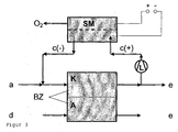
- a further embodiment of the invention shows FIG. 3 , There, the cathode exhaust gas and the anode exhaust gas is passed together through a catalytic burner, where the oxygen is removed to form water vapor and optionally CO 2 from the exhaust gas.
- a catalytic burner where the oxygen is removed to form water vapor and optionally CO 2 from the exhaust gas.
- the supply and discharge of the reactants by valves (not in FIG. 3 drawn) switched so that a circuit with the fan is created.
- the product water from the burner can, for example, in turn be deposited by absorptive methods.
Description
- Die Erfindung betrifft ein Hochtemperatur-Polymerelektrolyt-Brennstoffzellensystem (HT-PEFC), insbesondere ein mit einer dotierten Polybenzimidazol (PBI)-Membran, sowie ein Verfahren zum Betreiben eines solchen Systems.
- Die Polymerelektrolyt-Brennstoffzelle (engl. Polymer Electrolyte Fuel Cell, PEFC) ist eine Niedertemperatur-Brennstoffzelle. Für Betriebstemperaturen bis 100 °C werden regelmäßig feste Polymermembranen, beispielsweise aus Nafion, eingesetzt.
- Für höhere Betriebstemperaturen bis ca. 200 °C sind Nafion Membranen jedoch regelmäßig nicht mehr geeignet, da sie bei diesen Temperaturen nicht genügend Feuchtigkeit aufweisen und ihre Leitfähigkeit somit deutlich absinkt. Ferner sind sie bei Temperaturen oberhalb von 150 °C thermisch instabil. In diesen Temperaturbereichen werden daher Membranen aus Polyimid, wie beispielsweise aus Polybenzimidazol (PBI), verwendet, in welchen Phosphorsäure oder Schwefelsäure als Elektrolyt gebunden ist. Diese Materialien benötigen keine hohe relative Feuchte der Reaktionsgase, so dass ein Wassermanagement entbehrlich ist.
- PBI-Membranen ermöglichen eine neue Generation von Polymerelektrolyt-Brennstoffzellen, die in der Regel kostengünstiger, effizienter und zuverlässiger sind als konventionelle Niedertemperatur-Brennstoffzellensysteme. Zudem greifen sie auf eine vereinfachte Gasaufbereitung zurück, die durch einen hohe Kohlenmonoxid- und Schwefeltoleranz gekennzeichnet ist. Ferner zeichnet sich der Betrieb einer HT-PEFC durch eine einfache Steuerung aus.
- Technisch problematisch kann jedoch ein zu hoher Wassergehalt im Brenngas sein, der nachteilig zu einem Säureaustrag aus der Membran führen kann. Dadurch sinkt die Leitfähigkeit des Elektrolyten dauerhaft. Als Folge muss durch geeignete Wahl der konkreten Betriebszustände strikt darauf geachtet werden, dass kein flüssiges Wasser innerhalb der Brennstoffzelle entstehen kann.
- Flüssiges Wasser kann bei zu niedriger Betriebstemperatur, bei zu geringer Luftzahl oder bei einem Gas cross over in die Membran aufgenommen werden. Als geeignete Gegenmaßnahmen während des laufenden Betriebs können die Betriebstemperatur und die Luftzahl gesteigert werden, um die relative Luftfeuchtigkeit anzusenken, und so die Gefahr der Bildung von flüssigem Produktwasser entgegen wirken.
- Wird der Brennstoffzellenstapel jedoch abgeschaltet und kommt es dann dabei automatisch zu einer Abkühlung der Komponenten, so kann ohne vorherige Spülung mit Stickstoff eine Diffusion der restlichen Reaktionsgase Sauerstoff und Wasserstoff durch die Membran hindurch an die Katalysatorschichten erfolgen, die dort regelmäßig zur Ausbildung von flüssigem Wasser führt.
- Zudem regiert die Säure, insbesondere die Phosphorsäure in der Membran hygroskopisch, so dass auch Wasser aus der feuchten Umgebungsluft in einer derartigen Menge aufgenommen werden kann, die sich negativ auf die Leitfähigkeit der gesamten Membran auswirkt.
- Bei bekannten Hochtemperatur-Polymerelektrolyt-Brennstoffzellensystemen (HT-PEFC) werden daher die Brennstoffzellen während des Aufheizens oder auch nach dem Abschalten mit einem inerten Gas, z. B. mit Stickstoff, gespült, um die Bildung von flüssigem Wasser innerhalb der Zellen zu vermeiden. Das funktioniert jedoch nur, wenn immer eine ausreichende Menge an Spülgas vorhanden ist, beispielsweise in Form von bereitgestellten Druckgasflaschen.
- Als Nachteil haben sich aber in einem solchen Fall das zusätzliche Gewicht der Gasflaschen sowie die Notwendigkeit einer Füllstandsüberwachung herausgestellt. Der Austausch der Gasflaschen in regelmäßigen Zeiträumen bewirkt zusätzliche Mehrkosten und eine mögliche Einschränkung hinsichtlich des Anwendungsbereiches.
- Aus
JP 2004 288 458 A - Aufgabe der Erfindung ist es, ein Hochtemperatur-Polymerelektrolyt-Brennstoffzellensystem (HT-PEFC) zu schaffen, bei dem die vorgenannten Nachteile überwunden werden, insbesondere der Säureaustrag aus den Membranen verhindert werden kann. Ferner ist es Aufgabe der Erfindung, ein Verfahren zum Betreiben eines solchen Brennstoffzellensystems zur Verfügung zu stellen.
- Die Aufgaben der Erfindung werden gelöst durch ein Hochtemperatur-Polymerelektrolyt-Brennstoffzellensystem mit der Gesamtheit der Merkmale des Hauptanspruchs sowie durch ein Verfahren zum Betreiben eines solchen Systems gemäß Nebenanspruch. Vorteilhafte Ausführungsformen sind den jeweils darauf rückbezogenen Unteransprüchen zu entnehmen.
- Im Rahmen der Erfindung wurde gefunden, dass es Vorteile mit sich bringt, wenn anstelle des extern zugeführten inerten Spülgases, welches bislang während des Aufheizens oder des Abkühlens eines Brennstoffzellensystems zur Spülung desselben eingesetzt wurde, dieses nunmehr vorteilhaft direkt in dem Brennstoffzellensystem selbst generiert werden kann.
- Diese Erzeugung von Inertgas erfolgt erfindungsgemäß beispielsweise durch eine Sauerstoffabreicherung aus der vorhandenen Umgebungsluft oder auch aus einem im Kreislauf geführten Abgasstrom der Brennstoffzelle. Die Abreicherung des Sauerstoffs aus dem System soll deshalb erzielt werden, weil ohne den Sauerstoff keine Umwandlung zu flüssigem Wasser erfolgen kann, welches bekanntermaßen zu dem nachteiligen Säureaustrag führt.
- Für die Abreicherung von Sauerstoff aus dem Umfeld der Elektrolytmembran stehen prinzipiell mehrere Möglichkeiten zur Verfügung.
- Zum einen kann der Sauerstoff aus der Umgebungsluft oder einem Abgas durch eine Verbrennung mit Wasserstoff entfernt werden. In diesem Fall muss das entstehende Wasser direkt, das heißt vor Eintritt des Brennergases in die Zelle abgetrennt werden. Die Verbrennung sollte zudem stöchiometrisch erfolgen, dass heißt, dass wenigstens soviel Wasserstoff zugeführt wird, dass der gesamte Sauerstoff zu Wasser reagieren kann. Als ein dafür geeignetes Mittel ist beispielsweise ein Katalytbrenner zu nennen.
- Eine weitere Alternative zur Sauerstofferntfernung aus der Umgebungsluft ist eine Vorrichtung, bei der der Sauerstoff als Sauerstoffionen durch einen Elektrolyten abtransportiert wird, ähnlich wie bei einer Hochtemperatur-Brennstoffzelle (SOFC).
- Zur Sauerstoffentfernung aus der Luft können ebenfalls Vorrichtungen eingesetzt werden, die ein zur Absorption von Wasser geeignetes Mittel (Trockenmittel) aufweisen. Dies sind chemische Verbindungen mit einer besonderen inneren Struktur. Sie schließen aufgrund ihrer chemischen und strukturellen Beschaffenheit Wassermoleküle ein und ändern im Anschluss daran durch intermolekulare Kräfte ihre räumliche Molekülstruktur. Wassermoleküle können so nicht mehr aus der Struktur entweichen und bleiben gebunden. Vorteilhaft können diese Stoffe durch Wärme wieder regeneriert werden, d. h. durch eine ca. 0,5...2 Stunden dauernde Erwärmung auf ca. 130 °C kann das gebundene Wasser wieder ausgetrieben werden und die Stoffe sind erneut verwendbar. Für den Einsatz in dieser Erfindung wären insbesondere Absorberpatronen mit Silicagel oder Zeolithen geeignet.
- Vorteilhaft ist auch eine oder mehrere zusätzliche Möglichkeiten, Wasser an gekühlten Abscheidern aus zu kondensieren. Dazu bieten sich insbesondere Peltierelemente an, die auf einfache Weise die entsprechend tiefen Kühltemperaturen bereitstellen können, die weit unterhalb der Umgebungstemperatur liegen sollten. Die dabei einzustellende Temperatur sollte vorteilhaft unterhalb von 5 °C liegen.
- Nachfolgend wird der Gegenstand der Erfindung anhand mehrerer Ausführungsbeispiele und weiterer Figuren näher erläutert, ohne dass der Gegenstand der Erfindung dadurch beschränkt wird. Es zeigen:
- Figur 1:
- HT-PEFC System mit O2-Entfernung über eine Sauerstoffionentransportvorrichtung im Kathodenkreislauf.
- Figur 2:
- HT-PEFC System mit Absorberpatronen im Anoden- und Kathodenkreislauf.
- Figur 3:
- HT-PEFC System mit O2- und H2-Entfernung über einen Zirkulationskreislauf mit einem Katalytbrenner.
- In den Figuren bedeuten:
- BZ
- HT-PEFC Brennstoffzelle, stellvertretend für das gesamte HT-PEFC System, mit
- A
- Anode
- K
- Kathode
- KB
- Katalytbrenner
- WA
- Wasserabscheider
- AP
- Adsorberpatrone
- SM
- Sauerstoffionen leitende Membran
- L
- Lüfter, bzw. Pumpe
- a
- Luft, mit (+) und ohne (-) Wasser
- b
- Wasserstoff, mit (+) und ohne (-) Wasser
- c
- Stickstoff, mit (+) und ohne (-) Sauerstoff
- d
- Reformat
- e
- Abgas
- Eine erste Ausführungsform der Erfindung ist in
Figur 1 dargestellt. Dort ist in einem Hochtemperatur-Polymerelektrolyt-Brennstoffzellensystem (HT-PEFC) als separates Mittel zur Entfernung von Sauerstoff eine separate Abreicherungszelle, die im Aufbau einer SOFC entspricht, vorgesehen. Diese ist im Umluftkreislauf auf der Kathodenseite angeordnet. Um die Zelle in der Abschaltphase von Sauerstoff abzureichern, wird die Abreicherungszelle extern mit Strom und Spannung beaufschlagt. Die Bildung und Wanderung von Sauerstoffionen durch den keramischen Elektrolyten entfernt so weitgehend den Sauerstoff aus dem Kreislauf. Der Sauerstoff wird somit auf einen Gehalt zwischen 5 und 1 Vol.-%, vorteilhaft auf einen Gehalt kleiner 1 Vol.-%, und insbesondere kleiner als 0,1 Vol.-% reduziert. - Vorteilhaft bei dieser Ausgestaltung kann der dabei verwendete Lüfter während des regulären Betriebs der HT-PEFC zur Umwälzung der Kathodenluft eingesetzt werden, wodurch die Gleichverteilung des kathodenseitigen Sauerstoffpartialdrucks positiv beeinflusst wird. Der in der Abreicherungszelle abgeschiedene Sauerstoff kann entweder direkt an die Umgebung geführt oder für eine spätere Verwendung zwischengespeichert werden.
- Als weitere Ausgestaltung dieser Variante ist auch vorgesehen, den in dem System vorhandenen Sauerstoff zunächst elektrochemisch umzusetzen. Dies ist aber auf Grund von elektrochemischen Gegebenheiten nur bis zu einem gewissen Grad möglich, ohne die Zellen irreversibel zu schädigen. Anschließend oder auch gleichzeitig erfolgt die Abreicherung des Sauerstoffs durch die vorher beschriebene Abreicherungszelle.
- Die Abreicherungszelle selbst kann im Vergleich zum HT-PEFC Stapel klein und kompakt aufgebaut sein. Beispielsweise benötigt ein HT-PEFC Stack der 5 kW-Klasse, ein äußeres Volumen von ca. 20 L. Das innere Volumen der Kathode, d. h. der Luftmenge, liegt dann bei etwa 2 L, wenn man übliche Verteilerstrukturen (Manifolds) und Kanalgeometrien voraussetzt. Inklusive der in
Figur 1 gezeigten Komponenten für die Luftzirkulation, wie z. B. Lüfter, Ventile und Verrohrung, ergibt sich für das gesamte abzureichernde Luftvolumen ein Wert von maximal 5 L. Davon sind ca. 21 % Sauerstoff, d. h. ca. 1 L. - Im Fall der Abschaltung, bzw. Abkühlung des Stapels steht zur Abreicherung dieser Menge ein Zeitintervall Δt zur Verfügung, welches ungefähr der Abkühlzeit von 160 °C auf 120 °C entspricht. Bis zu diesen Temperaturen ist die Gefahr der Wasserausscheidung noch sehr gering. Dies kann überschlägig zu Δt = 10 min, bzw. 600 s abgeschätzt werden. Die Abreicherungszelle müsste demnach einen mittleren Strom I bereitstellen, der sich errechnen lässt aus:

mit - NO2
- = 1 1 / 22,414 l/mol = 0,045 mol
- Δt
- = 300 s,
- F
- = 96485 A s/mol
- Auch auf der Anodenseite kann der so erzeugte Stickstoff zur Inertisierung genutzt werden. Möglich wird dies unter Zuhilfenahme geeigneter Schalt- und Regelventile.
- Ergänzt werden kann das erfindungsgemäße System sowohl auf der Kathodenseite, als auch auf der Anodenseite um Wasserabscheider, die in den Kreisläufen angeordnet sind und dort die Gase trocknen.
- Anstelle eines Wasserabscheiders kann auch eine Absorberpatrone eingesetzt werden. In
Figur 2 ist ein weiteres Ausführungsbeispiel der Erfindung zu sehen. Dabei ist vorteilhaft sowohl in dem Anodenkreislauf, als auch in dem Kathodenkreislauf jeweils eine Absorberpatrone angeordnet, die insbesondere Wasser aus den jeweiligen Kreislaufmedien absorbiert und damit dem Kreislauf entzieht. Für die Absorption von Wasser aus Luft auf der Kathodenseite wären Silicagel oder Zeolithe ebenso geeignet, wie als Absorptionsmaterial für den wasserstoffhaltigen Anodenkreislauf.Vorteil haft kann das in den Absorberpatronen absorbierte Wasser während des Betriebs des HT-PEFC Systems durch Erhitzung wieder desorbiert werden, so dass die Absorberpatronen regelmäßig auf lange Zeit im System verbleiben können und nicht ausgewechselt werden müssen. - Eine weitere Ausgestaltung der Erfindung zeigt
Figur 3 . Dort wird das Kathodenabgas sowie das Anodenabgas gemeinsam durch einen Katalytbrenner geleitet, wo der Sauerstoff unter Bildung von Wasserdampf und gegebenenfalls CO2 aus dem Abgas entfernt wird. Dazu werden die Zu- und Ableitungen der Reaktanden durch Ventile (nicht inFigur 3 eingezeichnet) so geschaltet, dass ein Kreislauf mit dem Lüfter entsteht. Das Produktwasser aus dem Brenner kann beispielsweise wiederum durch absorptive Verfahren abgeschieden werden.
Claims (12)
- Hochtemperatur-Polymerelektrolyt-Brennstoffzellensystem (HT-PEFC), umfassend wenigstens eine Brennstoffzelle- mit einer Anode, einem Anodenraum, einer Kathode, einem Kathodenraum sowie einer zwischen Anode und Kathode angeordneten, mit Säure dotierten Polybenzimidazol (PBI)-Membran,- mit wenigstens einem Betriebsmittelkreislauf, und- mit wenigstens einem zusätzlichen, separaten Mittel zur Entfernung von Sauerstoff und/oder Wasser aus dem Betriebsmittelkreislauf,dadurch gekennzeichnet,
dass das zusätzliche, separate Mittel eine Sauerstoff leitende Membran, eine Absorberpatrone oder ein Brenner zur Verbrennung von Abgasen aus der Brennstoffzelle ist. - Brennstoffzellensystem nach Anspruch 1,
mit einer elektrisch kontaktierten, Sauerstoff leitenden Membran, die im Kathodenkreislauf angeordnet ist, als zusätzliches, separates Mittel. - Brennstoffzellensystem nach Anspruch 1,
mit einer Adsorberpatrone, die im Kathodenkreislauf angeordnet ist oder mit einer Adsorberpatrone, die im Anodenkreislauf angeordnet ist, als zusätzliches, separates Mittel. - Brennstoffzellensystem nach Anspruch 1,
mit zwei Absorberpatronen, von denen jeweils eine im Anoden - und eine im Kathodenkreislauf angeordnet sind. - Brennstoffzellensystem nach Anspruch 1,
mit einem Katalytbrenner als Mittel zur Entfernung von Sauerstoff, als zusätzliches, separates Mittel. - Brennstoffzellensystem nach Anspruch 1 bis 5,
mit einem Brenner, sowie einer dem Brenner nachgeschalteten Vorrichtung zur Wasserabscheidung, wobei beide Bauteile gemeinsam in einem zusammengeführten Anoden- und Kathodenkreislauf angeordnet sind. - Verfahren zum Betreiben eines Hochtemperatur-Polymerelektrolyt-Brennstoffzellensystems (HT-PEFC), umfassend wenigstens eine Brennstoffzelle- mit einer Anode, einem Anodenraum, einer Kathode, einem Kathodenraum, einer zwischen Anode und Kathode angeordneten, Säure dotierten Polybenzimidazol (PBI)-Membran,- mit wenigstens einen Betriebsmittelkreislauf und- mit einem darin angeordneten zusätzlichen, separaten Mittel zur Entfernung von Sauerstoff und/oder Wasser aus dem in dem Betriebsmittelkreislauf,dadurch gekennzeichnet,
dass der Sauerstoff und/oder das Wasser mit Hilfe eine Sauerstoff leitenden Membran, einer Absorberpatrone oder einem Brenner zur Verbrennung von Abgasen aus der Brennstoffzelle entfernt wird. - Verfahren nach Anspruch 7, bei dem die Entfernung von Sauerstoff und/oder Wasser während des Aufheizens oder des Abkühlens des Systems durchgeführt wird.
- Verfahren nach Anspruch 7 bis 8, bei dem aus dem im Kreislauf geführten Kathodenabgas oder aus dem im Kreislauf geführten Anodenabgas oder sowohl aus dem im Kreislauf geführten Anodenabgas als auch aus dem im Kreislauf geführten Kathodenabgas Wasser mit Hilfe jeweils einer Absorberpatrone entfernt wird.
- Verfahren nach Anspruch 7 bis 8, bei dem aus dem im Kreislauf geführten Kathodenabgas Sauerstoff mit Hilfe einer keramischen, Sauerstoff leitenden Membran entfernt wird.
- Verfahren nach Anspruch 7 bis 8, bei dem das Anoden- und das Kathodenabgas gemeinsam einem Brenner zugeführt werden, und der in dem Abgas enthaltene Sauerstoff verbrannt wird.
- Verfahren nach Anspruch 11, bei dem das Wasser aus dem Wasseraufweisenden Abgas des Brenners abgeschieden wird, bevor das wasserfreie Abgas wieder der Brennstoffzelle zugeführt wird.
Applications Claiming Priority (2)
| Application Number | Priority Date | Filing Date | Title |
|---|---|---|---|
| DE102007026652A DE102007026652A1 (de) | 2007-06-08 | 2007-06-08 | Hochtemperatur-Polymerelektrolyt-Brennstoffzellensystem sowie Verfahren zum Betreiben desselben |
| PCT/DE2008/000847 WO2008148368A1 (de) | 2007-06-08 | 2008-05-17 | Hochtemperatur-polymerelektrolyt-brennstoffzellensystem sowie verfahren zum betreiben desselben |
Publications (2)
| Publication Number | Publication Date |
|---|---|
| EP2153486A1 EP2153486A1 (de) | 2010-02-17 |
| EP2153486B1 true EP2153486B1 (de) | 2012-12-19 |
Family
ID=39720278
Family Applications (1)
| Application Number | Title | Priority Date | Filing Date |
|---|---|---|---|
| EP08758088A Not-in-force EP2153486B1 (de) | 2007-06-08 | 2008-05-17 | Hochtemperatur-polymerelektrolyt-brennstoffzellensystem sowie verfahren zum betreiben desselben |
Country Status (3)
| Country | Link |
|---|---|
| EP (1) | EP2153486B1 (de) |
| DE (1) | DE102007026652A1 (de) |
| WO (1) | WO2008148368A1 (de) |
Families Citing this family (3)
| Publication number | Priority date | Publication date | Assignee | Title |
|---|---|---|---|---|
| DE102014018230B4 (de) * | 2014-12-04 | 2016-10-27 | Mann + Hummel Gmbh | Akkumulator-Anordnung für ein Fahrzeug |
| DE102017213789A1 (de) * | 2017-08-08 | 2019-02-14 | Audi Ag | Brennstoffzellensystem |
| DE102019214711A1 (de) * | 2019-09-26 | 2021-04-01 | Robert Bosch Gmbh | Verfahren zum Betreiben eines Brennstoffzellensystems, Brennstoffzellensystem |
Family Cites Families (5)
| Publication number | Priority date | Publication date | Assignee | Title |
|---|---|---|---|---|
| AU739786B2 (en) * | 1998-02-25 | 2001-10-18 | Ballard Power Systems Inc. | Direct dimethyl ether fuel cells |
| JP4361301B2 (ja) | 2003-03-20 | 2009-11-11 | 本田技研工業株式会社 | 熱電変換装置 |
| US7520916B2 (en) * | 2005-07-25 | 2009-04-21 | Bloom Energy Corporation | Partial pressure swing adsorption system for providing hydrogen to a vehicle fuel cell |
| JP4877711B2 (ja) * | 2005-08-04 | 2012-02-15 | 本田技研工業株式会社 | 燃料電池システム |
| US8129057B2 (en) * | 2005-12-06 | 2012-03-06 | Honda Motor Co., Ltd. | High efficiency fuel cell system |
-
2007
- 2007-06-08 DE DE102007026652A patent/DE102007026652A1/de not_active Withdrawn
-
2008
- 2008-05-17 WO PCT/DE2008/000847 patent/WO2008148368A1/de active Application Filing
- 2008-05-17 EP EP08758088A patent/EP2153486B1/de not_active Not-in-force
Also Published As
| Publication number | Publication date |
|---|---|
| DE102007026652A1 (de) | 2008-12-11 |
| WO2008148368A1 (de) | 2008-12-11 |
| EP2153486A1 (de) | 2010-02-17 |
Similar Documents
| Publication | Publication Date | Title |
|---|---|---|
| DE102010005294B4 (de) | Brennstoffzellensystem und Verfahren zum Spülen von Wasser aus einem Brennstoffzellenstapel bei Systemabschaltung | |
| DE19857398B4 (de) | Brennstoffzellensystem, insbesondere für elektromotorisch angetriebene Fahrzeuge | |
| DE102015122144A1 (de) | Befeuchter mit integriertem Wasserabscheider für ein Brennstoffzellensystem, Brennstoffzellensystem sowie Fahrzeug mit einem solchen | |
| EP1407506A2 (de) | Verfahren und vorrichtung zum entionisieren von kühlmedien für brennstoffzellen | |
| DE102010048253B4 (de) | Verfahren zur Rekonditionierung eines Brennstoffzellenstapels | |
| DE102011010893B4 (de) | Verfahren zum Auslösen und Deaktivieren eines Brennstoffzellenstapel-Wiederaufbereitungsprozesses | |
| EP2153486B1 (de) | Hochtemperatur-polymerelektrolyt-brennstoffzellensystem sowie verfahren zum betreiben desselben | |
| EP1194967A1 (de) | Htm-brennstoffzelle oder -batterie mit verminderter elektrolytausspülung und verfahren zum starten | |
| WO2008116604A9 (de) | Brennstoffzelle sowie verfahren zu deren herstellung | |
| DE102004024844A1 (de) | Elektrodenpaste zur Herstellung einer Katalysatorschicht für eine elektrochemische Zelle sowie Verfahren zur Herstellung einer Katalysatorschicht | |
| WO2002059992A2 (de) | Verfahren zur verbesserung des wasserhaushalts von brennstoffzellen | |
| EP4008035B1 (de) | Befeuchter, brennstoffzellenvorrichtung mit befeuchter sowie kraftfahrzeug | |
| DE102020100599A1 (de) | Verfahren für einen Froststart eines Brennstoffzellensystems, Brennstoffzellensystem und Kraftfahrzeug mit einem solchen | |
| DE102019133091A1 (de) | Brennstoffzellenvorrichtung, Kraftfahrzeug mit einer Brennstoffzellenvorrichtung und Verfahren zum Betreiben einer Brennstoffzellenvorrichtung | |
| DE102017215474A1 (de) | Verfahren zum Betreiben eines Brennstoffzellensystems sowie entsprechend eingerichtetes Brennstoffzellensystem und Fahrzeug | |
| EP4037812B1 (de) | Befeuchter, brennstoffzellenvorrichtung sowie kraftfahrzeug mit einer brennstoffzellenvorrichtung | |
| EP4169099B1 (de) | Verfahren für einen froststart einer brennstoffzellenvorrichtung, brennstoffzellenvorrichtung sowie kraftfahrzeug mit einer brennstoffzellenvorrichtung | |
| DE102017220362A1 (de) | Befeuchtermodul für ein Brennstoffzellensystem, Brennstoffzellensystem, Verfahren zum Regenerieren eines Befeuchtermoduls sowie Fahrzeug | |
| DE19945713A1 (de) | Hochtemperatur-Polymer-Elektrolyt-Membran (HTM)-Brennstoffzelle, HTM-Brennstoffzellenanlage, Verfahren zum Betreiben einer HTM-Brennstoffzelle und/oder einer HTM-Brennstoffzellenanlage | |
| EP1465276B1 (de) | Niedertemperatur-Brennstoffzelle sowie Verfahren zum Betreiben derselben | |
| DE102015212251A1 (de) | Brennstoffzellensystem mit Vorrichtung zur Frostkonditionierung sowie Verfahren zur Frostkonditionierung eines Brennstoffzellensystems | |
| DE102022200621A1 (de) | Verfahren zur Herstellung einer Kontaktplatte | |
| DE10260501A1 (de) | Gasdiffusionselektrode mit einer Schicht zur Steuerung der Querdiffusion von Wasser | |
| DE102022203691A1 (de) | Verfahren zum Betrieb einer Elektrolyseanlage und Elektrolyseanlage | |
| DE102013004637A1 (de) | Befeuchtungseinrichtung zur Befeuchtung eines Prozessgases, Brennstoffzellenanordnung umfassend eine solche sowie Fahrzeug |
Legal Events
| Date | Code | Title | Description |
|---|---|---|---|
| PUAI | Public reference made under article 153(3) epc to a published international application that has entered the european phase |
Free format text: ORIGINAL CODE: 0009012 |
|
| 17P | Request for examination filed |
Effective date: 20091120 |
|
| AK | Designated contracting states |
Kind code of ref document: A1 Designated state(s): AT BE BG CH CY CZ DE DK EE ES FI FR GB GR HR HU IE IS IT LI LT LU LV MC MT NL NO PL PT RO SE SI SK TR |
|
| AX | Request for extension of the european patent |
Extension state: AL BA MK RS |
|
| DAX | Request for extension of the european patent (deleted) | ||
| 17Q | First examination report despatched |
Effective date: 20101012 |
|
| GRAP | Despatch of communication of intention to grant a patent |
Free format text: ORIGINAL CODE: EPIDOSNIGR1 |
|
| GRAS | Grant fee paid |
Free format text: ORIGINAL CODE: EPIDOSNIGR3 |
|
| GRAA | (expected) grant |
Free format text: ORIGINAL CODE: 0009210 |
|
| AK | Designated contracting states |
Kind code of ref document: B1 Designated state(s): AT BE BG CH CY CZ DE DK EE ES FI FR GB GR HR HU IE IS IT LI LT LU LV MC MT NL NO PL PT RO SE SI SK TR |
|
| REG | Reference to a national code |
Ref country code: GB Ref legal event code: FG4D Free format text: NOT ENGLISH |
|
| REG | Reference to a national code |
Ref country code: CH Ref legal event code: EP |
|
| REG | Reference to a national code |
Ref country code: AT Ref legal event code: REF Ref document number: 589802 Country of ref document: AT Kind code of ref document: T Effective date: 20130115 |
|
| REG | Reference to a national code |
Ref country code: DE Ref legal event code: R096 Ref document number: 502008008916 Country of ref document: DE Effective date: 20130228 |
|
| PG25 | Lapsed in a contracting state [announced via postgrant information from national office to epo] |
Ref country code: ES Free format text: LAPSE BECAUSE OF FAILURE TO SUBMIT A TRANSLATION OF THE DESCRIPTION OR TO PAY THE FEE WITHIN THE PRESCRIBED TIME-LIMIT Effective date: 20130330 Ref country code: LT Free format text: LAPSE BECAUSE OF FAILURE TO SUBMIT A TRANSLATION OF THE DESCRIPTION OR TO PAY THE FEE WITHIN THE PRESCRIBED TIME-LIMIT Effective date: 20121219 Ref country code: SE Free format text: LAPSE BECAUSE OF FAILURE TO SUBMIT A TRANSLATION OF THE DESCRIPTION OR TO PAY THE FEE WITHIN THE PRESCRIBED TIME-LIMIT Effective date: 20121219 Ref country code: FI Free format text: LAPSE BECAUSE OF FAILURE TO SUBMIT A TRANSLATION OF THE DESCRIPTION OR TO PAY THE FEE WITHIN THE PRESCRIBED TIME-LIMIT Effective date: 20121219 Ref country code: NO Free format text: LAPSE BECAUSE OF FAILURE TO SUBMIT A TRANSLATION OF THE DESCRIPTION OR TO PAY THE FEE WITHIN THE PRESCRIBED TIME-LIMIT Effective date: 20130319 |
|
| REG | Reference to a national code |
Ref country code: NL Ref legal event code: VDEP Effective date: 20121219 |
|
| REG | Reference to a national code |
Ref country code: LT Ref legal event code: MG4D |
|
| PG25 | Lapsed in a contracting state [announced via postgrant information from national office to epo] |
Ref country code: LV Free format text: LAPSE BECAUSE OF FAILURE TO SUBMIT A TRANSLATION OF THE DESCRIPTION OR TO PAY THE FEE WITHIN THE PRESCRIBED TIME-LIMIT Effective date: 20121219 Ref country code: GR Free format text: LAPSE BECAUSE OF FAILURE TO SUBMIT A TRANSLATION OF THE DESCRIPTION OR TO PAY THE FEE WITHIN THE PRESCRIBED TIME-LIMIT Effective date: 20130320 Ref country code: SI Free format text: LAPSE BECAUSE OF FAILURE TO SUBMIT A TRANSLATION OF THE DESCRIPTION OR TO PAY THE FEE WITHIN THE PRESCRIBED TIME-LIMIT Effective date: 20121219 |
|
| PG25 | Lapsed in a contracting state [announced via postgrant information from national office to epo] |
Ref country code: CZ Free format text: LAPSE BECAUSE OF FAILURE TO SUBMIT A TRANSLATION OF THE DESCRIPTION OR TO PAY THE FEE WITHIN THE PRESCRIBED TIME-LIMIT Effective date: 20121219 Ref country code: EE Free format text: LAPSE BECAUSE OF FAILURE TO SUBMIT A TRANSLATION OF THE DESCRIPTION OR TO PAY THE FEE WITHIN THE PRESCRIBED TIME-LIMIT Effective date: 20121219 Ref country code: SK Free format text: LAPSE BECAUSE OF FAILURE TO SUBMIT A TRANSLATION OF THE DESCRIPTION OR TO PAY THE FEE WITHIN THE PRESCRIBED TIME-LIMIT Effective date: 20121219 Ref country code: IS Free format text: LAPSE BECAUSE OF FAILURE TO SUBMIT A TRANSLATION OF THE DESCRIPTION OR TO PAY THE FEE WITHIN THE PRESCRIBED TIME-LIMIT Effective date: 20130419 Ref country code: BG Free format text: LAPSE BECAUSE OF FAILURE TO SUBMIT A TRANSLATION OF THE DESCRIPTION OR TO PAY THE FEE WITHIN THE PRESCRIBED TIME-LIMIT Effective date: 20130319 |
|
| PG25 | Lapsed in a contracting state [announced via postgrant information from national office to epo] |
Ref country code: RO Free format text: LAPSE BECAUSE OF FAILURE TO SUBMIT A TRANSLATION OF THE DESCRIPTION OR TO PAY THE FEE WITHIN THE PRESCRIBED TIME-LIMIT Effective date: 20121219 Ref country code: PT Free format text: LAPSE BECAUSE OF FAILURE TO SUBMIT A TRANSLATION OF THE DESCRIPTION OR TO PAY THE FEE WITHIN THE PRESCRIBED TIME-LIMIT Effective date: 20130419 Ref country code: NL Free format text: LAPSE BECAUSE OF FAILURE TO SUBMIT A TRANSLATION OF THE DESCRIPTION OR TO PAY THE FEE WITHIN THE PRESCRIBED TIME-LIMIT Effective date: 20121219 Ref country code: PL Free format text: LAPSE BECAUSE OF FAILURE TO SUBMIT A TRANSLATION OF THE DESCRIPTION OR TO PAY THE FEE WITHIN THE PRESCRIBED TIME-LIMIT Effective date: 20121219 |
|
| PLBE | No opposition filed within time limit |
Free format text: ORIGINAL CODE: 0009261 |
|
| STAA | Information on the status of an ep patent application or granted ep patent |
Free format text: STATUS: NO OPPOSITION FILED WITHIN TIME LIMIT |
|
| PG25 | Lapsed in a contracting state [announced via postgrant information from national office to epo] |
Ref country code: DK Free format text: LAPSE BECAUSE OF FAILURE TO SUBMIT A TRANSLATION OF THE DESCRIPTION OR TO PAY THE FEE WITHIN THE PRESCRIBED TIME-LIMIT Effective date: 20121219 |
|
| 26N | No opposition filed |
Effective date: 20130920 |
|
| PG25 | Lapsed in a contracting state [announced via postgrant information from national office to epo] |
Ref country code: HR Free format text: LAPSE BECAUSE OF FAILURE TO SUBMIT A TRANSLATION OF THE DESCRIPTION OR TO PAY THE FEE WITHIN THE PRESCRIBED TIME-LIMIT Effective date: 20121219 Ref country code: CY Free format text: LAPSE BECAUSE OF FAILURE TO SUBMIT A TRANSLATION OF THE DESCRIPTION OR TO PAY THE FEE WITHIN THE PRESCRIBED TIME-LIMIT Effective date: 20121219 |
|
| PG25 | Lapsed in a contracting state [announced via postgrant information from national office to epo] |
Ref country code: IT Free format text: LAPSE BECAUSE OF FAILURE TO SUBMIT A TRANSLATION OF THE DESCRIPTION OR TO PAY THE FEE WITHIN THE PRESCRIBED TIME-LIMIT Effective date: 20121219 Ref country code: MC Free format text: LAPSE BECAUSE OF FAILURE TO SUBMIT A TRANSLATION OF THE DESCRIPTION OR TO PAY THE FEE WITHIN THE PRESCRIBED TIME-LIMIT Effective date: 20121219 |
|
| REG | Reference to a national code |
Ref country code: DE Ref legal event code: R097 Ref document number: 502008008916 Country of ref document: DE Effective date: 20130920 |
|
| REG | Reference to a national code |
Ref country code: IE Ref legal event code: MM4A |
|
| PG25 | Lapsed in a contracting state [announced via postgrant information from national office to epo] |
Ref country code: IE Free format text: LAPSE BECAUSE OF NON-PAYMENT OF DUE FEES Effective date: 20130517 |
|
| PG25 | Lapsed in a contracting state [announced via postgrant information from national office to epo] |
Ref country code: MT Free format text: LAPSE BECAUSE OF FAILURE TO SUBMIT A TRANSLATION OF THE DESCRIPTION OR TO PAY THE FEE WITHIN THE PRESCRIBED TIME-LIMIT Effective date: 20121219 |
|
| PG25 | Lapsed in a contracting state [announced via postgrant information from national office to epo] |
Ref country code: TR Free format text: LAPSE BECAUSE OF FAILURE TO SUBMIT A TRANSLATION OF THE DESCRIPTION OR TO PAY THE FEE WITHIN THE PRESCRIBED TIME-LIMIT Effective date: 20121219 |
|
| PG25 | Lapsed in a contracting state [announced via postgrant information from national office to epo] |
Ref country code: HU Free format text: LAPSE BECAUSE OF FAILURE TO SUBMIT A TRANSLATION OF THE DESCRIPTION OR TO PAY THE FEE WITHIN THE PRESCRIBED TIME-LIMIT; INVALID AB INITIO Effective date: 20080517 Ref country code: LU Free format text: LAPSE BECAUSE OF NON-PAYMENT OF DUE FEES Effective date: 20130517 |
|
| REG | Reference to a national code |
Ref country code: FR Ref legal event code: PLFP Year of fee payment: 9 |
|
| PGFP | Annual fee paid to national office [announced via postgrant information from national office to epo] |
Ref country code: GB Payment date: 20160523 Year of fee payment: 9 Ref country code: DE Payment date: 20160409 Year of fee payment: 9 Ref country code: CH Payment date: 20160526 Year of fee payment: 9 |
|
| PGFP | Annual fee paid to national office [announced via postgrant information from national office to epo] |
Ref country code: BE Payment date: 20160523 Year of fee payment: 9 Ref country code: AT Payment date: 20160519 Year of fee payment: 9 Ref country code: FR Payment date: 20160523 Year of fee payment: 9 |
|
| REG | Reference to a national code |
Ref country code: DE Ref legal event code: R119 Ref document number: 502008008916 Country of ref document: DE |
|
| REG | Reference to a national code |
Ref country code: CH Ref legal event code: PL |
|
| REG | Reference to a national code |
Ref country code: AT Ref legal event code: MM01 Ref document number: 589802 Country of ref document: AT Kind code of ref document: T Effective date: 20170517 |
|
| GBPC | Gb: european patent ceased through non-payment of renewal fee |
Effective date: 20170517 |
|
| PG25 | Lapsed in a contracting state [announced via postgrant information from national office to epo] |
Ref country code: AT Free format text: LAPSE BECAUSE OF NON-PAYMENT OF DUE FEES Effective date: 20170517 |
|
| PG25 | Lapsed in a contracting state [announced via postgrant information from national office to epo] |
Ref country code: CH Free format text: LAPSE BECAUSE OF NON-PAYMENT OF DUE FEES Effective date: 20170531 Ref country code: LI Free format text: LAPSE BECAUSE OF NON-PAYMENT OF DUE FEES Effective date: 20170531 |
|
| REG | Reference to a national code |
Ref country code: FR Ref legal event code: ST Effective date: 20180131 |
|
| REG | Reference to a national code |
Ref country code: BE Ref legal event code: MM Effective date: 20170531 |
|
| PG25 | Lapsed in a contracting state [announced via postgrant information from national office to epo] |
Ref country code: DE Free format text: LAPSE BECAUSE OF NON-PAYMENT OF DUE FEES Effective date: 20171201 Ref country code: GB Free format text: LAPSE BECAUSE OF NON-PAYMENT OF DUE FEES Effective date: 20170517 |
|
| PG25 | Lapsed in a contracting state [announced via postgrant information from national office to epo] |
Ref country code: FR Free format text: LAPSE BECAUSE OF NON-PAYMENT OF DUE FEES Effective date: 20170531 |
|
| PG25 | Lapsed in a contracting state [announced via postgrant information from national office to epo] |
Ref country code: BE Free format text: LAPSE BECAUSE OF NON-PAYMENT OF DUE FEES Effective date: 20170531 |