EP2153155B1 - Abnehmbares füllermodul - Google Patents
Abnehmbares füllermodul Download PDFInfo
- Publication number
- EP2153155B1 EP2153155B1 EP08754158.7A EP08754158A EP2153155B1 EP 2153155 B1 EP2153155 B1 EP 2153155B1 EP 08754158 A EP08754158 A EP 08754158A EP 2153155 B1 EP2153155 B1 EP 2153155B1
- Authority
- EP
- European Patent Office
- Prior art keywords
- module
- heat source
- filler element
- filler
- lower portion
- Prior art date
- Legal status (The legal status is an assumption and is not a legal conclusion. Google has not performed a legal analysis and makes no representation as to the accuracy of the status listed.)
- Active
Links
Images



Classifications
-
- F—MECHANICAL ENGINEERING; LIGHTING; HEATING; WEAPONS; BLASTING
- F27—FURNACES; KILNS; OVENS; RETORTS
- F27D—DETAILS OR ACCESSORIES OF FURNACES, KILNS, OVENS OR RETORTS, IN SO FAR AS THEY ARE OF KINDS OCCURRING IN MORE THAN ONE KIND OF FURNACE
- F27D1/00—Casings; Linings; Walls; Roofs
- F27D1/02—Crowns; Roofs
- F27D1/021—Suspended roofs
-
- C—CHEMISTRY; METALLURGY
- C03—GLASS; MINERAL OR SLAG WOOL
- C03B—MANUFACTURE, SHAPING, OR SUPPLEMENTARY PROCESSES
- C03B18/00—Shaping glass in contact with the surface of a liquid
- C03B18/02—Forming sheets
- C03B18/16—Construction of the float tank; Use of material for the float tank; Coating or protection of the tank wall
-
- C—CHEMISTRY; METALLURGY
- C03—GLASS; MINERAL OR SLAG WOOL
- C03B—MANUFACTURE, SHAPING, OR SUPPLEMENTARY PROCESSES
- C03B18/00—Shaping glass in contact with the surface of a liquid
- C03B18/02—Forming sheets
- C03B18/20—Composition of the atmosphere above the float bath; Treating or purifying the atmosphere above the float bath
- C03B18/22—Controlling or regulating the temperature of the atmosphere above the float tank
-
- F—MECHANICAL ENGINEERING; LIGHTING; HEATING; WEAPONS; BLASTING
- F27—FURNACES; KILNS; OVENS; RETORTS
- F27D—DETAILS OR ACCESSORIES OF FURNACES, KILNS, OVENS OR RETORTS, IN SO FAR AS THEY ARE OF KINDS OCCURRING IN MORE THAN ONE KIND OF FURNACE
- F27D1/00—Casings; Linings; Walls; Roofs
- F27D1/04—Casings; Linings; Walls; Roofs characterised by the form, e.g. shape of the bricks or blocks used
-
- F—MECHANICAL ENGINEERING; LIGHTING; HEATING; WEAPONS; BLASTING
- F27—FURNACES; KILNS; OVENS; RETORTS
- F27D—DETAILS OR ACCESSORIES OF FURNACES, KILNS, OVENS OR RETORTS, IN SO FAR AS THEY ARE OF KINDS OCCURRING IN MORE THAN ONE KIND OF FURNACE
- F27D1/00—Casings; Linings; Walls; Roofs
- F27D1/16—Making or repairing linings ; Increasing the durability of linings; Breaking away linings
- F27D1/1621—Making linings by using shaped elements, e.g. bricks
-
- F—MECHANICAL ENGINEERING; LIGHTING; HEATING; WEAPONS; BLASTING
- F27—FURNACES; KILNS; OVENS; RETORTS
- F27D—DETAILS OR ACCESSORIES OF FURNACES, KILNS, OVENS OR RETORTS, IN SO FAR AS THEY ARE OF KINDS OCCURRING IN MORE THAN ONE KIND OF FURNACE
- F27D99/00—Subject matter not provided for in other groups of this subclass
- F27D99/0001—Heating elements or systems
-
- F—MECHANICAL ENGINEERING; LIGHTING; HEATING; WEAPONS; BLASTING
- F27—FURNACES; KILNS; OVENS; RETORTS
- F27D—DETAILS OR ACCESSORIES OF FURNACES, KILNS, OVENS OR RETORTS, IN SO FAR AS THEY ARE OF KINDS OCCURRING IN MORE THAN ONE KIND OF FURNACE
- F27D99/00—Subject matter not provided for in other groups of this subclass
- F27D99/0001—Heating elements or systems
- F27D99/0006—Electric heating elements or system
- F27D2099/0008—Resistor heating
Definitions
- This invention relates generally to industrial furnaces and, more particularly to, an apparatus and a method for using a roof filler module to access and replace a failed heat source while the industrial furnace remains in operation.
- Industrial furnaces are used in many applications such as, but not limited to, producing glass on a tin bath, heat treating, smelting and/or refining metals, calcining coke, incinerating waste and the like.
- Industrial furnaces are often constructed of refractory materials, such as taught by U.S. Patents 6,427,610 and 4,960,058 , the entire teachings of which are incorporated by reference into this specification.
- the use of hanger bricks and filler bricks for roof construction is effective in industrial furnaces, particularly for making glass.
- a tin bath system in an industrial furnace is currently used to manufacture flat glass.
- the glass is formed in a flat sheet by dispersing molten glass across a bath of molten tin alloy and because the glass has the lower specific gravity, it floats on the molten metal.
- the interface of the glass and molten tin alloy is nearly perfectly flat, forming one side of the sheet.
- the sheet is heated by the molten metal on one side and by a heat source on the other side of the sheet, in order to allow for a process of stretching and relaxing the sheet, which results in a substantially flat top surface.
- a heat source sometimes fails. Over time, failure of one or more heat sources may jeopardize the glass-forming process, and in extreme cases, may require shutting the process down to repair or replace the failed heat sources. The resulting loss of production time can be very costly to a manufacturer.
- a filler element that allows replacement of a failed heat source during tin bath operation is highly desirable, particularly where only a small area of the industrial furnace is exposed to the surrounding environment.
- the above and other objects of this invention can be attained, at least in part, with a filler element for an industrial furnace roof.
- the filler element can have a lower portion with a hot face where the hot face can be generally rectangular and/or generally flat.
- the lower portion can have at least one aperture.
- the lower portion can engage with at least one hanger brick.
- This invention can include at least one module having a generally rectangular bottom with at least one protuberance located on a bottom of the module.
- Each protuberance can correspond to at least one aperture of the lower portion.
- Each module can be moveably mounted with respect to the lower portion to engage the protuberance with the aperture.
- Each module can have at least one bore extending through both the module and the protuberance.
- Each module desirably but not necessarily has at least one lifting lug.
- This invention can include at least one heat source positionable through the bore of the module and/or each heat source positionable through the aperture of the lower portion.
- a filler element according to this invention can easily provide replacement of a failed heat source while the furnace is in operation. According to this invention, removing a filler element minimizes industrial furnace exposure to the surrounding environment when replacing a failed heat source.
- This invention also relates to a method for operating an industrial furnace wherein at least one heat source is energized to increase an internal temperature of the industrial furnace.
- Each heat source can be positionable through at least one bore of at least one filler element of a roof of the industrial furnace.
- Each bore can extend through the module and/or the bore can extend through at least one protuberance on a bottom of the module.
- Each heat source can be positionable through at least one aperture in a lower portion. Each aperture can be engageable with a protuberance.
- This method can include running the heat source until failure.
- This method can include deenergizing the failed heat source while the operating temperature of the industrial furnace is increased.
- a guide sleeve can be placed above the module of the failed heat source.
- the guide sleeve can be engageable to support adjacent furnace bricks, and the guide sleeve can direct removal and/or insertion of a module.
- a lifting tool can be engaged with at least one lifting lug on the module of the failed heat source.
- the lifting tool can be made of at least one hook and at least one slidable and/or lockable stay.
- the hook can engage the lifting lug and the stay can contact a surface of the module to form a firm linkage in a locked position.
- the filler module of the failed heat source can be removed from the roof of the industrial furnace with the lifting tool and can be directed by the guide sleeve.
- the lifting tool can be disengaged from the filler module of the failed heat source and can engage the lifting tool with a filler module of a replacement heat source.
- the filler module of the replacement heat source can be inserted into the roof of the industrial furnace, with the lifting tool and the guide sleeve.
- the lifting tool can be disengaged from the filler module of the replacement heat source, removing the guide sleeve and energizing the replacement heat source.
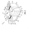
- FIG.1 shows an assembled filler element 10 according to one embodiment of this invention.
- Filler element 10 can comprise one or more blocks of material capable of withstanding the high temperatures of an industrial furnace.
- Such materials can include steel, stainless steel, alloy, chrome alloy, nickel alloy, ceramic, refractory and/or any other suitable material known to those skilled in the art.
- Common refractory materials can include zircon, fireclay, silica, dolomite, magnesite, alumina, chromite, sillimanite and/or silicon carbide.
- Suitable refractory materials can be chosen by those skilled in the art based on industrial furnace criteria such as, but not limited to, operating temperature, pH or chemistry, cost of refractory materials, insulation requirements and maintenance intervals.
- Filler element 10 can be of various sizes and shapes, depending upon the needs of the industrial furnace design. Typically but not necessarily, for some glass furnaces, filler element 10 has a width of about 6 inches to about 24 inches. In one embodiment of this invention, filler element 10 has a width of about 10 inches. In another embodiment of this invention, filler element 10 has a width of about 20 inches. Filler element 10 can be oriented in any suitable direction, such as generally parallel to and/or perpendicular to a length of the industrial furnace. Any other suitable angular orientation with respect to the length of the industrial furnace, such as 30 degrees, 45 degrees, 60 degrees and/or other suitable angles, is possible.
- the shape of filler element 10 is generally rectangular. Other shapes can include combinations of straight lines and/or curved lines forming regular or irregular polygons, and can be used for an industrial furnace roof. Cross sectional shapes of filler element 10 may include but are not limited to a triangle, a square, a trapezoid, a hexagon and/or an octagon. Industrial furnace roof construction can include filler elements 10 of different shapes and/or sizes used in the same roof construction, but preferably minimize a number of different types of blocks used for construction.
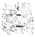
- filler element 10 can include lower portion 12.
- the lower portion 12 may be referred to as a base, base member, base tile and/or base block.
- at least a hot face 14 of lower portion 12 can be positioned toward an inside chamber volume of the industrial furnace.
- Hot face 14 can be generally rectangular and generally smooth, for example to form a substantially flat roof inside the industrial furnace.
- Materials for lower portion 12 can be of a relatively dense refractory material such as sillimanite and/or silicon carbide.
- lower portion 12 can include at least one aperture 16 such as a hole, a bore, a cutout, a notch and/or any other suitable void.
- multiple apertures 16 through lower portion 12 are positioned in opposite corners from each other.
- Aperture 16 can be generally round, generally rectangular and/or of another suitable shape. Minimizing a size of aperture 16 can reduce exposure of the industrial furnace to the surrounding environment during replacement of a failed heat source 26.
- at least one side of aperture 16 is tapered, angled and/or beveled, for example so that the opening of the aperture 16 is larger on a top of lower portion 12 than on a bottom of lower portion 12.
- Lower portion 12 can include at least one shoulder 18, for example that forms a lip, a ridge, a notch, a groove, a recess and/or another suitable engagement for horizontal and/or vertical support by at least one hanger brick.
- Filler element 10 can include module 20 to house, support and/or hold heater, heat element or heat source 26.
- Module 20 can be fabricated from the same or similar dense refractory material as lower portion 12.
- the module can be any of various shapes and/or various sizes generally equal to and/or smaller than lower portion 12 to facilitate construction and/or maintenance repairs of the industrial furnace.
- module 20 has at least one protuberance 22 such as a knob, a nub and/or a lug on a bottom side.
- Protuberance 22 can correspond, such as in shape and/or size, to aperture 16 of lower portion 12.
- Protuberance 22 can engage with, enter in, nest in, rest in and/or couple with aperture 16.
- protuberance 22 can be tapered to correspond to a taper of aperture 16.
- Module 20 can have at least one bore 24.
- module 20 can have three bores 24 substantially in a line.
- Bore 24 can be a hole, an aperture and/or an opening such that heat source 26 can pass in and/or through bore 24.
- module 20 has sufficient thickness, particularly in and/or around an area of bore 24 to prevent cracking and/or failure of the refractory during normal handling and/or use.
- bore 24 extends through module 20 and also through protuberance 22.
- Module 20 can be moveably mounted with respect to lower portion 12 to allow heat source 26 replacement.
- Module 20 can comprise insulation layer 34 which can be a heat resistor or of a material that reduces heat transfer to a surrounding environment but may not have properties that withstand direct contact with an internal atmosphere and/or temperature of the industrial furnace.
- Suitable refractory material for insulation layer 34 can include various alumina-silica compounds, such as insulating fire brick and the like. Such fire brick materials can be more cost effective than dense refractories that can be used in lower portion 12.
- Insulation layer 34 may have slot 32 as shown in FIG. 3 , according to one embodiment of this invention.
- Slot 32 or any other suitable groove, channel and/or trough may accommodate washers 42, and can be included in the assembly of filler element 20.
- Washer 42 or any other suitable spacer, ferrule and/or disc can prevent damage to softer materials used in insulation layer 34.
- One or more washers 42 can be used above and/or below insulation layer 34. According to certain embodiments of this invention, washers 42 are ceramic.
- Rod 30 can be used to structurally attache and/or secure module 20 and insulation layer 34 together.
- rod 30 is constructed of a high alloy material capable of withstanding the operating temperatures of the industrial furnace.
- Rod 30 can be threaded and/or have a hook or another connector on one or both ends.
- Rod 30 can also secure or attach lifting lug 28 to module 20.
- Lifting lug 28 can be a loop, an eyelet and/or have any other suitable design to remove module 20.
- a nut can be used to secure or attach lifting lug 28 to rod 30.
- Heat source 26 can be an electric induction heater, an electric resistance heater, an electric arc heater, a radio frequency generator, a combustion device and/or any other suitable equipment for supplying thermal energy or transferring heat to an industrial furnace.
- Electricity requirements can include low voltage, high voltage, alternating current, direct current, high amperage, low amperage and/or any other suitable supply.
- Fuels for combustion may include, for example, hydrogen, natural gas, liquid hydrocarbons, coal, wood and/or other suitable material capable of releasing heat when burned.
- heat source 26 includes a plurality, such as three, electric resistance heater elements.
- Each heater element can be in the shape of a rod that can be bundled and/or fixed to another rod with a block at a bottom or lower end of the rods, to provide stability.
- Filler element 10 can comprise at least one seal brick 36. According to one embodiment of this invention and as shown in FIG. 1 , filler element 10 can include six seal bricks 36. Seal brick 36 can be of, for example, insulated fire brick material. Seal bricks 36 can act as an end, a cap, a divider and/or a spacer block. Seal bricks 36 can remain loose until placement in an industrial furnace and/or can be secured using one or more fastening methods, such as those described generally below.
- Insulation block 3 8 can be part of filler element 10, depending on the insulation and/or the heating requirements of the industrial furnace.
- Insulation block 38 can be referred to as a blank module. According to one embodiment of this invention, there is at least one insulation block 38 for each module 20. Insulation blocks 38 and modules 20 can alternate along a length of the industrial furnace. One or more layers or strata 43 can form insulation block 38. Strata 43 can be affixed with one or more fastening methods described generally below. Suitable materials for insulation block 38 include insulating fire brick and/or other refractory materials, such as those described above. Insulation block 38 may also include a lifting eye or loop 40.
- Refractory bricks and/or shapes can have outside corners rounded, squared and/or chamfered.
- the inside corners of the refractory bricks and/or shapes can be squared and/or rounded.
- Filler element 20 of this invention can readily be adapted for use in refractory structures having arches, curves, vertical walls and/or other angles and/or other locations in the industrial furnace that may require heat source 26.
- fastening refractory materials together include mechanical fasteners, such as screws, dowels, clamps, pins, nails, interference fit elements and/or other suitable connection devices.
- Other fastening methods may include the use of cements, mortars, mastic, adhesives and/or other suitable binders.
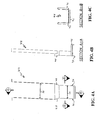
- Filler element 10 may comprise guide sleeve 44 as shown in FIGS. 4A, 4B and 4C , according to some embodiments of this invention.
- Guide sleeve 44 can comprise brace 46 to support, stabilize, steady and/or facilitate placement of guide sleeve 44 on, above, and/or around module 20.
- guide sleeve 44 is constructed of sheet metal and includes taper 48 where upper width 50 is greater than lower width 52. Taper 48 can assist, guide, direct, and/or aid in the insertion of module 20 while installing a replacement heat source 26.
- Guide sleeve 44 can hold seal brick 36, module 20 and/or insulation block 38 in position, such as during replacement of a failed heat source 26.
- Lifting tool 54 may comprise lifting tool 54 as illustrated in FIGS. 5A, 5B and 5C , and according to certain embodiments of this invention.
- Lifting tool 54 can comprise handle 56 for lifting, raising, lowering and/or positioning lifting tool 54.
- Handle 56 can be replaced by any other suitable mechanical linkage or device to interface with a powered lifting device such as a crane, a chain fall and/or a hoist.
- Lifting tool 54 may comprise hook 58 for engaging lifting lug 28.
- Stay 60 can be rigid flat stock material and can have at least one collar 62 to position lifting tool 54 and provide a slidable attachment for lifting tool 54 with respect to stay 60.
- Stay 60 can also comprise lock mechanism 64, so that when engaged, lock mechanism 64 fixes lifting tool 54 with respect to stay 60.
- lock mechanism 64 can comprise a wing nut and a threaded connection to provide manual engagement.
- Lifting tool 54 can also comprise foot 66 and may be flat stock bent to form a 90-degree angle, for example. According to one embodiment of this invention, foot 66 contacts a top of module 20 so that when lifting tool 54 engages lifting lug 28, a rigid and/or a firm connection and/or coupling can resist twisting.
- This invention can comprise a method for industrial furnace operation.
- One method can include energizing heat source 26, for example to complete an electric circuit for a resistance heater.
- the method may comprise operating heat source 26 until failure, such as when a current discontinuity occurs in a resistence heater.
- the failed heat source 26 can be deenergized for safety reasons.
- the method can further comprise engaging or placing guide sleeve 44 on and/or above module 20 with failed heat source 26 while operating the industrial furnace.
- the method may also comprise positioning lifting tool 54 on module 20 with failed heat source 26 to engage hook 58 with lifting lug 28 and contacting a top of module 20 with foot 66 of stay 60 so that a rigid and/or firm connection can be made when applying lock mechanism 64.
- the unitized lifting tool 54 and module 20 can be removed using the guide sleeve 44.
- the lifting tool 54 can be removed from module 20 with the failed heat source 26 and engaged with a second module 20 with a replacement heat source 26, to allow insertion into the roof of the industrial furnace, with guide sleeve 44.
- Lifting tool 54 can be removed from module 20 with the replacement heat source 26.
- Guide sleeve 44 can be removed. Heat source 26 can then be energized.
Landscapes
- Engineering & Computer Science (AREA)
- Mechanical Engineering (AREA)
- General Engineering & Computer Science (AREA)
- Chemical & Material Sciences (AREA)
- Materials Engineering (AREA)
- Organic Chemistry (AREA)
- Furnace Housings, Linings, Walls, And Ceilings (AREA)
- Furnace Details (AREA)
Claims (17)
- Füllelement (10) für das Dach eines industriellen Ofens, umfassend:einen unteren Abschnitt (12) mit einer heißen Seite (14), wobei die heiße Seite eine im Wesentlichen flache Form aufweist, wobei der untere Abschnitt mindestens eine Öffnung (16) aufweist und der untere Abschnitt mit mindestens einem Hängeziegel in Eingriff bringbar ist,mindestens ein Modul (20) mit einem im Allgemeinen rechtwinkligen Boden mit mindestens einem Vorsprung (22), der sich am Boden des Moduls befindet, wobei der Vorsprung mit mindestens einer Öffnung des unteren Abschnitts korrespondiert, wobei das mindestens eine Modul beweglich mit Bezug auf den unteren Abschnitt montiert ist, wobei der Vorsprung in die Öffnung eingreift, wobei das mindestens eine Modul mindestens eine Bohrung (24) aufweist, die sich sowohl durch das Modul als auch durch den Vorsprung erstreckt, wobei das mindestens eine Modul mindestens eine Hebeöse (28) aufweist und mindestens eine Wärmequelle (26), welche durch die Bohrung des Moduls positioniert werden kann und wobei jede Wärmequelle durch die Öffnung des unteren Abschnitts positioniert werden kann.
- Füllelement nach Anspruch 1, wobei der untere Abschnitt aus einem dichten feuerfesten Material hergestellt ist.
- Füllelement nach Anspruch 1, wobei das Modul Abschlussziegel, Isolierblöcke und Isolierschichten umfasst, die über dem unteren Abschnitt angebracht werden können, um den industriellen Ofen von einem umgebenden Umfeld zu isolieren.
- Füllelement nach Anspruch 3, wobei die Abschlussziegel, die Isolierblöcke und die Isolierschichten aus isoliertem Feuerziegel hergestellt sind.
- Füllelement nach Anspruch 3, wobei sechs Abschlussziegel die mindestens eine Isolierschicht umgeben.
- Füllelement nach Anspruch 3, weiter umfassend eine Stange, um die Isolierschicht und die Hebeöse zu befestigen.
- Füllelement nach Anspruch 3, wobei die Isolierschicht einen Schlitz auf einem Boden aufweist.
- Füllelement nach Anspruch 3, wobei der Isolierblock mindestens eine Hebeschlaufe umfasst.
- Füllelement nach Anspruch 3, wobei der Isolierblock drei Lagen umfasst.
- Füllelement nach Anspruch 1, weiter umfassend Ringscheiben, um eine Wärmequelle zu tragen.
- Füllelement nach Anspruch 1, wobei die Wärmquelle ein elektrisches Heizelement ist.
- Füllelement nach Anspruch 1, wobei der Vorsprung von einer oberen Seite zu einem engeren Boden spitz zuläuft und die Öffnung entsprechend von einer oberen Seite zu einem engeren Boden spitz zuläuft.
- Füllelement nach Anspruch 1, wobei sich mindestens drei Bohrungen durch jedes Modul erstrecken.
- Füllelement nach Anspruch 1, wobei zwei Hebeösen auf einer oberen Seite des Moduls montiert sind.
- Verfahren zum Betrieb eines industriellen Ofens, umfassend:Einschalten von mindestens einer Wärmequelle, um eine interne Temperatur des industriellen Ofens zu erhöhen, wobei die mindestens eine Wärmequelle durch mindestens eine Bohrung von mindestens einem Füllelement eines Dachs des industriellen Ofens positioniert werden kann und sich die mindestens eine Bohrung durch ein Modul und durch mindestens einen Vorsprung auf einem Boden des Moduls erstreckt, wobei die mindestens eine Wärmequelle durch die mindestens eine Öffnung in einem unteren Abschnitt positioniert und die mindestens eine Öffnung mit einem Vorsprung eingegriffen werden kann,Laufen lassen der Wärmequelle bis zum Ausfall;Abschalten der ausgefallenen Wärmequelle, während die Temperatur des industriellen Ofens erhöht bleibt;Anbringen einer Führungshülse über dem Modul der ausgefallenen Wärmequelle, und wobei die Führungshülse in Eingriff bringbar ist, um benachbarte Ofenziegel zu tragen, und die Führungshülse die Entfernung und die Einführung eines Moduls leitet;In Eingriff bringen eines Hebewerkzeugs mit mindestens einer Hebeöse auf dem Modul der ausgefallenen Wärmequelle, wobei das Hebewerkzeug mindestens einen Haken und mindestens einen gleitbaren und blockierbaren Halter umfasst, der Haken die Abhebeöse eingreift und der Halter mit einer Oberfläche des Moduls in Kontakt kommt, um eine feste Verbindung in einer blockierten Position zu bilden;Entfernen des mindestens einen Füllmoduls mit der mindestens einen ausgefallenen Wärmquelle vom Dach des industriellen Ofens, wobei das Hebewerkzeug und die Entfernung durch die Führungshülse geleitet sind;Ausklinken des Hebewerkzeugs vom mindestens einen Füllmodul der mindestens einen ausgefallenen Wärmequelle;In Eingriff bringen des Hebewerkzeugs mit einem Füllmodul von mindestens einer Ersatzwärmequelle;Einführen des Füllmoduls der Ersatzwärmquelle in das Dach des industriellen Ofens mit dem Hebewerkzeug und der Führungshülse,Ausklinken des Hebewerkzeugs von dem mindestens einen Füllmodul der Ersatzwärmequelle;Entfernen der Führungshülse; und Einschalten der Ersatzwärmequelle.
- Verfahren nach Anspruch 15, wobei die Führungshülse aus Blech hergestellt ist.
- Verfahren nach Anspruch 15, wobei der Hebewerkzeughalter und der Blockiermechanismus eine Flügelmutter umfassen.
Applications Claiming Priority (2)
| Application Number | Priority Date | Filing Date | Title |
|---|---|---|---|
| US11/799,673 US8428096B2 (en) | 2007-05-01 | 2007-05-01 | Removable filler module |
| PCT/US2008/005581 WO2008134078A1 (en) | 2007-05-01 | 2008-05-01 | Removable filler module |
Publications (2)
| Publication Number | Publication Date |
|---|---|
| EP2153155A1 EP2153155A1 (de) | 2010-02-17 |
| EP2153155B1 true EP2153155B1 (de) | 2016-11-16 |
Family
ID=39563325
Family Applications (1)
| Application Number | Title | Priority Date | Filing Date |
|---|---|---|---|
| EP08754158.7A Active EP2153155B1 (de) | 2007-05-01 | 2008-05-01 | Abnehmbares füllermodul |
Country Status (4)
| Country | Link |
|---|---|
| US (1) | US8428096B2 (de) |
| EP (1) | EP2153155B1 (de) |
| JP (1) | JP5362706B2 (de) |
| WO (1) | WO2008134078A1 (de) |
Families Citing this family (1)
| Publication number | Priority date | Publication date | Assignee | Title |
|---|---|---|---|---|
| US8693518B2 (en) * | 2009-09-09 | 2014-04-08 | Merkle International Inc. | High temperature industrial furnace roof system |
Family Cites Families (44)
| Publication number | Priority date | Publication date | Assignee | Title |
|---|---|---|---|---|
| US2116202A (en) * | 1935-02-16 | 1938-05-03 | Sulzer Ag | Electric smelting furnace cover |
| US2509225A (en) * | 1945-12-14 | 1950-05-30 | Harold H Gilbert | Quick releasing safety crane hook |
| US2509228A (en) | 1949-02-26 | 1950-05-30 | Tennessee Valley Authority | Electric furnace for phosphate reduction |
| DE1133344B (de) * | 1960-05-17 | 1962-07-19 | Knapsack Ag | Deckel mit abnehmbaren Teilen fuer elektrische OEfen |
| DE1209038B (de) * | 1962-11-23 | 1966-01-13 | Hans Lingl | Ebene Haengedecke fuer Tunneloefen |
| US3404209A (en) * | 1965-05-25 | 1968-10-01 | Brooke Frank Wharton | Furnace construction and utilization |
| US3568611A (en) * | 1968-11-12 | 1971-03-09 | Johns Manville | Furnace construction |
| GB1331459A (en) * | 1970-12-22 | 1973-09-26 | Steetley Mfg Ltd | Furnace construction |
| US3824936A (en) * | 1973-02-28 | 1974-07-23 | F Merkle | Basic suspended roof construction for industrial furnaces |
| US3849586A (en) * | 1974-02-20 | 1974-11-19 | Combustion Eng | Electric arc furnaces and refractory shapes therefor |
| US3976424A (en) * | 1975-02-18 | 1976-08-24 | Sola Basic Industries, Inc. | Refractory roof construction for the heating chamber of an industrial furnace |
| GB1562203A (en) * | 1975-08-11 | 1980-03-05 | Johns Manville | Prefabricated insulating blocks for lining walls and roofs |
| SE7611156L (sv) * | 1975-10-10 | 1977-04-11 | Foseco Trading Ag | Block av eldfast betong |
| US4137422A (en) * | 1977-04-19 | 1979-01-30 | Barbashin Oleg A | Airtight metal melting furnace |
| DE2921702C2 (de) | 1979-05-29 | 1983-10-27 | Mannesmann AG, 4000 Düsseldorf | Elektro-Metallschmelzofen mit Bodenabstich |
| US4340411A (en) * | 1981-01-05 | 1982-07-20 | Ppg Industries, Inc. | Float glass forming chamber with auxiliary heating modules |
| US4449345A (en) * | 1981-03-20 | 1984-05-22 | Manville Service Corporation | Insulation module hardware |
| US4473015A (en) * | 1981-10-30 | 1984-09-25 | J. T. Thorpe Company | Self-supporting fabric reinforced refractory fiber composite curtain |
| US4463689A (en) * | 1982-01-07 | 1984-08-07 | Merkle Engineers, Inc. | High temperature furnace nose construction |
| US4424756A (en) * | 1982-02-01 | 1984-01-10 | Merkle Engineers, Inc. | Suspended roof construction for industrial furnaces |
| US4475470A (en) * | 1982-02-01 | 1984-10-09 | Merkle Engineers, Inc. | Suspended roof construction for industrial furnaces |
| AT388444B (de) * | 1984-09-18 | 1989-06-26 | Voest Alpine Ag | Elektroofen |
| US4638617A (en) * | 1984-10-19 | 1987-01-27 | Merkle Engineers, Inc. | Refractory curtain wall |
| JPS61186413A (ja) * | 1985-02-12 | 1986-08-20 | Daido Steel Co Ltd | 取鍋精錬装置 |
| US4705475A (en) * | 1986-04-25 | 1987-11-10 | Merkle Engineers, Inc. | Insulated refractory shield |
| US4754716A (en) * | 1987-05-15 | 1988-07-05 | Merkle Engineers, Inc. | Refractory shield removable toe |
| US4809621A (en) * | 1988-04-14 | 1989-03-07 | Merkle Engineers, Inc. | Refractory brick protection for membrane boiler walls |
| US4864945A (en) * | 1988-08-12 | 1989-09-12 | Merkle Engineers, Inc. | Curved nose refractory construction |
| US4887277A (en) * | 1988-09-22 | 1989-12-12 | A. Finkl & Sons Co. | Electric arc furnace |
| US4860306A (en) * | 1988-10-05 | 1989-08-22 | Vacuum Furnace Systems Corporation | Hot zone employing graphite heating elements |
| US4960058A (en) * | 1989-10-26 | 1990-10-02 | Merkle Engineers, Inc. | Self-positioning refractory structure |
| US5241559A (en) * | 1992-03-30 | 1993-08-31 | Emc International, Inc. | Electric arc furnace roof |
| US5357540A (en) * | 1992-08-28 | 1994-10-18 | Merkle Engineers Inc. | High temperature industrial furnace roof structure |
| LU88585A1 (de) | 1995-02-08 | 1996-08-23 | Wurth Paul Sa | Lichtbogenofen zum Einschmelzen von Metallen |
| US5905752A (en) * | 1996-07-15 | 1999-05-18 | Amsted Industries Incorporated | ARC furnace fume collection system and method |
| US5899151A (en) * | 1997-06-13 | 1999-05-04 | Merkle Engineers, Inc. | Industrial furnace roof assembly and components thereof |
| IT1299736B1 (it) * | 1998-02-11 | 2000-04-04 | Danieli Off Mecc | Volta raffreddata per forni elettrici ad arco e per forni siviera |
| US6058859A (en) * | 1998-11-23 | 2000-05-09 | Colosimo, Jr.; Samuel A. | Refractory support device and associated method |
| US6427610B1 (en) * | 2000-10-11 | 2002-08-06 | Merkle Engineers, Inc. | High temperature industrial furnace roof structure |
| FR2815339B1 (fr) * | 2000-10-18 | 2003-01-10 | Saint Gobain Isover | Four de fusion electrique du verre, a elements de parois pivotants |
| JP2002231391A (ja) * | 2001-01-31 | 2002-08-16 | Tyco Electronics Amp Kk | シールドコネクタ組立体 |
| EP1323980A1 (de) * | 2001-12-31 | 2003-07-02 | Von Roll Umwelttechnik AG | Kühlbare Gewölbedecke |
| US7040241B2 (en) * | 2002-05-24 | 2006-05-09 | Merkle Engineers, Inc. | Refractory brick and refractory construction |
| JP4604693B2 (ja) * | 2003-12-25 | 2011-01-05 | 旭硝子株式会社 | フロートバスおよびフロート成形方法 |
-
2007
- 2007-05-01 US US11/799,673 patent/US8428096B2/en active Active
-
2008
- 2008-05-01 EP EP08754158.7A patent/EP2153155B1/de active Active
- 2008-05-01 JP JP2010506313A patent/JP5362706B2/ja active Active
- 2008-05-01 WO PCT/US2008/005581 patent/WO2008134078A1/en not_active Ceased
Non-Patent Citations (1)
| Title |
|---|
| None * |
Also Published As
| Publication number | Publication date |
|---|---|
| WO2008134078A1 (en) | 2008-11-06 |
| JP2010526273A (ja) | 2010-07-29 |
| EP2153155A1 (de) | 2010-02-17 |
| US8428096B2 (en) | 2013-04-23 |
| JP5362706B2 (ja) | 2013-12-11 |
| US20080271656A1 (en) | 2008-11-06 |
Similar Documents
| Publication | Publication Date | Title |
|---|---|---|
| GB2055182A (en) | Industrial furnace with side wall ceramic insulating modules | |
| US6427610B1 (en) | High temperature industrial furnace roof structure | |
| US8428096B2 (en) | Removable filler module | |
| EP2475947B1 (de) | Dachsystem für einen hochtemperaturindustrieofen | |
| JPS584271B2 (ja) | セラミツクヨウソ オヨビ セラミツクヨウソオフクムダンネツクミタテタイ | |
| US4263470A (en) | Holding device for electrical resistance elements in furnaces | |
| JP3649446B2 (ja) | 加熱炉及びライニング | |
| US4300882A (en) | Industrial furnace with side wall ceramic insulating modules | |
| CN119263594A (zh) | 窑炉热态情况下的烧枪更换方法及烧枪更换装置 | |
| JP3454662B2 (ja) | コークス炉炭化室の溶射修理方法 | |
| CN109983291B (zh) | 用于熔炉的壁系统、包括这种壁系统的熔炉以及用于设置这种壁系统的方法 | |
| CN219890138U (zh) | 一种隔焰式燃烧煅烧氧化锆的辊道窑炉 | |
| CN219995924U (zh) | 真空蒸馏炉电极结构 | |
| CN221319757U (zh) | 观察装置以及载板玻璃生产窑炉 | |
| CN221376297U (zh) | 一种加热炉用致密高铝砖 | |
| RU108128U1 (ru) | Электрическая печь для обжига вермикулита | |
| CN215810174U (zh) | 一种多温区管式炉 | |
| CN218566156U (zh) | 一种碳质耐火结构 | |
| CN220283898U (zh) | 一种炉体封堵的快捷装置 | |
| CN219223304U (zh) | 一种小温差电炉结构 | |
| CN217572511U (zh) | 一种坩埚取放杆 | |
| KR101290240B1 (ko) | 원통형 전기용해로 | |
| CN212179553U (zh) | 一种亚微米碳化硅隔焰板 | |
| SU1033829A1 (ru) | Способ дл подготовки резервных индукторов из влажной футеровки дл быстрой замены и приспособление дл его осуществлени | |
| CN209260250U (zh) | 导流筒外屏及导流筒 |
Legal Events
| Date | Code | Title | Description |
|---|---|---|---|
| PUAI | Public reference made under article 153(3) epc to a published international application that has entered the european phase |
Free format text: ORIGINAL CODE: 0009012 |
|
| 17P | Request for examination filed |
Effective date: 20091201 |
|
| AK | Designated contracting states |
Kind code of ref document: A1 Designated state(s): AT BE BG CH CY CZ DE DK EE ES FI FR GB GR HR HU IE IS IT LI LT LU LV MC MT NL NO PL PT RO SE SI SK TR |
|
| AX | Request for extension of the european patent |
Extension state: AL BA MK RS |
|
| DAX | Request for extension of the european patent (deleted) | ||
| 17Q | First examination report despatched |
Effective date: 20101108 |
|
| REG | Reference to a national code |
Ref country code: DE Ref legal event code: R079 Ref document number: 602008047407 Country of ref document: DE Free format text: PREVIOUS MAIN CLASS: F27D0001020000 Ipc: F27D0099000000 |
|
| GRAP | Despatch of communication of intention to grant a patent |
Free format text: ORIGINAL CODE: EPIDOSNIGR1 |
|
| RIC1 | Information provided on ipc code assigned before grant |
Ipc: F27D 99/00 20100101AFI20160628BHEP |
|
| INTG | Intention to grant announced |
Effective date: 20160720 |
|
| GRAS | Grant fee paid |
Free format text: ORIGINAL CODE: EPIDOSNIGR3 |
|
| GRAA | (expected) grant |
Free format text: ORIGINAL CODE: 0009210 |
|
| AK | Designated contracting states |
Kind code of ref document: B1 Designated state(s): AT BE BG CH CY CZ DE DK EE ES FI FR GB GR HR HU IE IS IT LI LT LU LV MC MT NL NO PL PT RO SE SI SK TR |
|
| RAP1 | Party data changed (applicant data changed or rights of an application transferred) |
Owner name: MERKLE INTERNATIONAL, INC. |
|
| REG | Reference to a national code |
Ref country code: GB Ref legal event code: FG4D |
|
| REG | Reference to a national code |
Ref country code: CH Ref legal event code: EP |
|
| REG | Reference to a national code |
Ref country code: IE Ref legal event code: FG4D |
|
| REG | Reference to a national code |
Ref country code: AT Ref legal event code: REF Ref document number: 846322 Country of ref document: AT Kind code of ref document: T Effective date: 20161215 |
|
| REG | Reference to a national code |
Ref country code: DE Ref legal event code: R096 Ref document number: 602008047407 Country of ref document: DE |
|
| PG25 | Lapsed in a contracting state [announced via postgrant information from national office to epo] |
Ref country code: LV Free format text: LAPSE BECAUSE OF FAILURE TO SUBMIT A TRANSLATION OF THE DESCRIPTION OR TO PAY THE FEE WITHIN THE PRESCRIBED TIME-LIMIT Effective date: 20161116 |
|
| REG | Reference to a national code |
Ref country code: NL Ref legal event code: MP Effective date: 20161116 |
|
| REG | Reference to a national code |
Ref country code: LT Ref legal event code: MG4D |
|
| REG | Reference to a national code |
Ref country code: AT Ref legal event code: MK05 Ref document number: 846322 Country of ref document: AT Kind code of ref document: T Effective date: 20161116 |
|
| PG25 | Lapsed in a contracting state [announced via postgrant information from national office to epo] |
Ref country code: LT Free format text: LAPSE BECAUSE OF FAILURE TO SUBMIT A TRANSLATION OF THE DESCRIPTION OR TO PAY THE FEE WITHIN THE PRESCRIBED TIME-LIMIT Effective date: 20161116 Ref country code: GR Free format text: LAPSE BECAUSE OF FAILURE TO SUBMIT A TRANSLATION OF THE DESCRIPTION OR TO PAY THE FEE WITHIN THE PRESCRIBED TIME-LIMIT Effective date: 20170217 Ref country code: NO Free format text: LAPSE BECAUSE OF FAILURE TO SUBMIT A TRANSLATION OF THE DESCRIPTION OR TO PAY THE FEE WITHIN THE PRESCRIBED TIME-LIMIT Effective date: 20170216 Ref country code: SE Free format text: LAPSE BECAUSE OF FAILURE TO SUBMIT A TRANSLATION OF THE DESCRIPTION OR TO PAY THE FEE WITHIN THE PRESCRIBED TIME-LIMIT Effective date: 20161116 Ref country code: NL Free format text: LAPSE BECAUSE OF FAILURE TO SUBMIT A TRANSLATION OF THE DESCRIPTION OR TO PAY THE FEE WITHIN THE PRESCRIBED TIME-LIMIT Effective date: 20161116 |
|
| REG | Reference to a national code |
Ref country code: FR Ref legal event code: PLFP Year of fee payment: 10 |
|
| PG25 | Lapsed in a contracting state [announced via postgrant information from national office to epo] |
Ref country code: FI Free format text: LAPSE BECAUSE OF FAILURE TO SUBMIT A TRANSLATION OF THE DESCRIPTION OR TO PAY THE FEE WITHIN THE PRESCRIBED TIME-LIMIT Effective date: 20161116 Ref country code: HR Free format text: LAPSE BECAUSE OF FAILURE TO SUBMIT A TRANSLATION OF THE DESCRIPTION OR TO PAY THE FEE WITHIN THE PRESCRIBED TIME-LIMIT Effective date: 20161116 Ref country code: ES Free format text: LAPSE BECAUSE OF FAILURE TO SUBMIT A TRANSLATION OF THE DESCRIPTION OR TO PAY THE FEE WITHIN THE PRESCRIBED TIME-LIMIT Effective date: 20161116 Ref country code: PT Free format text: LAPSE BECAUSE OF FAILURE TO SUBMIT A TRANSLATION OF THE DESCRIPTION OR TO PAY THE FEE WITHIN THE PRESCRIBED TIME-LIMIT Effective date: 20170316 Ref country code: AT Free format text: LAPSE BECAUSE OF FAILURE TO SUBMIT A TRANSLATION OF THE DESCRIPTION OR TO PAY THE FEE WITHIN THE PRESCRIBED TIME-LIMIT Effective date: 20161116 Ref country code: PL Free format text: LAPSE BECAUSE OF FAILURE TO SUBMIT A TRANSLATION OF THE DESCRIPTION OR TO PAY THE FEE WITHIN THE PRESCRIBED TIME-LIMIT Effective date: 20161116 |
|
| PG25 | Lapsed in a contracting state [announced via postgrant information from national office to epo] |
Ref country code: CZ Free format text: LAPSE BECAUSE OF FAILURE TO SUBMIT A TRANSLATION OF THE DESCRIPTION OR TO PAY THE FEE WITHIN THE PRESCRIBED TIME-LIMIT Effective date: 20161116 Ref country code: RO Free format text: LAPSE BECAUSE OF FAILURE TO SUBMIT A TRANSLATION OF THE DESCRIPTION OR TO PAY THE FEE WITHIN THE PRESCRIBED TIME-LIMIT Effective date: 20161116 Ref country code: DK Free format text: LAPSE BECAUSE OF FAILURE TO SUBMIT A TRANSLATION OF THE DESCRIPTION OR TO PAY THE FEE WITHIN THE PRESCRIBED TIME-LIMIT Effective date: 20161116 Ref country code: EE Free format text: LAPSE BECAUSE OF FAILURE TO SUBMIT A TRANSLATION OF THE DESCRIPTION OR TO PAY THE FEE WITHIN THE PRESCRIBED TIME-LIMIT Effective date: 20161116 Ref country code: SK Free format text: LAPSE BECAUSE OF FAILURE TO SUBMIT A TRANSLATION OF THE DESCRIPTION OR TO PAY THE FEE WITHIN THE PRESCRIBED TIME-LIMIT Effective date: 20161116 |
|
| REG | Reference to a national code |
Ref country code: DE Ref legal event code: R097 Ref document number: 602008047407 Country of ref document: DE |
|
| PG25 | Lapsed in a contracting state [announced via postgrant information from national office to epo] |
Ref country code: BG Free format text: LAPSE BECAUSE OF FAILURE TO SUBMIT A TRANSLATION OF THE DESCRIPTION OR TO PAY THE FEE WITHIN THE PRESCRIBED TIME-LIMIT Effective date: 20170216 |
|
| PLBE | No opposition filed within time limit |
Free format text: ORIGINAL CODE: 0009261 |
|
| STAA | Information on the status of an ep patent application or granted ep patent |
Free format text: STATUS: NO OPPOSITION FILED WITHIN TIME LIMIT |
|
| 26N | No opposition filed |
Effective date: 20170817 |
|
| PG25 | Lapsed in a contracting state [announced via postgrant information from national office to epo] |
Ref country code: SI Free format text: LAPSE BECAUSE OF FAILURE TO SUBMIT A TRANSLATION OF THE DESCRIPTION OR TO PAY THE FEE WITHIN THE PRESCRIBED TIME-LIMIT Effective date: 20161116 |
|
| REG | Reference to a national code |
Ref country code: CH Ref legal event code: PL |
|
| PG25 | Lapsed in a contracting state [announced via postgrant information from national office to epo] |
Ref country code: MC Free format text: LAPSE BECAUSE OF FAILURE TO SUBMIT A TRANSLATION OF THE DESCRIPTION OR TO PAY THE FEE WITHIN THE PRESCRIBED TIME-LIMIT Effective date: 20161116 |
|
| REG | Reference to a national code |
Ref country code: IE Ref legal event code: MM4A |
|
| PG25 | Lapsed in a contracting state [announced via postgrant information from national office to epo] |
Ref country code: CH Free format text: LAPSE BECAUSE OF NON-PAYMENT OF DUE FEES Effective date: 20170531 Ref country code: LI Free format text: LAPSE BECAUSE OF NON-PAYMENT OF DUE FEES Effective date: 20170531 |
|
| PG25 | Lapsed in a contracting state [announced via postgrant information from national office to epo] |
Ref country code: IE Free format text: LAPSE BECAUSE OF NON-PAYMENT OF DUE FEES Effective date: 20170501 |
|
| REG | Reference to a national code |
Ref country code: FR Ref legal event code: PLFP Year of fee payment: 11 |
|
| PG25 | Lapsed in a contracting state [announced via postgrant information from national office to epo] |
Ref country code: MT Free format text: LAPSE BECAUSE OF NON-PAYMENT OF DUE FEES Effective date: 20170501 |
|
| PG25 | Lapsed in a contracting state [announced via postgrant information from national office to epo] |
Ref country code: HU Free format text: LAPSE BECAUSE OF FAILURE TO SUBMIT A TRANSLATION OF THE DESCRIPTION OR TO PAY THE FEE WITHIN THE PRESCRIBED TIME-LIMIT; INVALID AB INITIO Effective date: 20080501 |
|
| PG25 | Lapsed in a contracting state [announced via postgrant information from national office to epo] |
Ref country code: CY Free format text: LAPSE BECAUSE OF NON-PAYMENT OF DUE FEES Effective date: 20161116 |
|
| PG25 | Lapsed in a contracting state [announced via postgrant information from national office to epo] |
Ref country code: IS Free format text: LAPSE BECAUSE OF FAILURE TO SUBMIT A TRANSLATION OF THE DESCRIPTION OR TO PAY THE FEE WITHIN THE PRESCRIBED TIME-LIMIT Effective date: 20170316 |
|
| PGFP | Annual fee paid to national office [announced via postgrant information from national office to epo] |
Ref country code: DE Payment date: 20250521 Year of fee payment: 18 |
|
| PGFP | Annual fee paid to national office [announced via postgrant information from national office to epo] |
Ref country code: GB Payment date: 20250521 Year of fee payment: 18 |
|
| PGFP | Annual fee paid to national office [announced via postgrant information from national office to epo] |
Ref country code: LU Payment date: 20250521 Year of fee payment: 18 Ref country code: BE Payment date: 20250521 Year of fee payment: 18 Ref country code: IT Payment date: 20250527 Year of fee payment: 18 |
|
| PGFP | Annual fee paid to national office [announced via postgrant information from national office to epo] |
Ref country code: FR Payment date: 20250528 Year of fee payment: 18 |
|
| PGFP | Annual fee paid to national office [announced via postgrant information from national office to epo] |
Ref country code: TR Payment date: 20250422 Year of fee payment: 18 |