EP2153144B1 - Storage compartment - Google Patents
Storage compartment Download PDFInfo
- Publication number
- EP2153144B1 EP2153144B1 EP08769840.3A EP08769840A EP2153144B1 EP 2153144 B1 EP2153144 B1 EP 2153144B1 EP 08769840 A EP08769840 A EP 08769840A EP 2153144 B1 EP2153144 B1 EP 2153144B1
- Authority
- EP
- European Patent Office
- Prior art keywords
- seal
- compartment
- external enclosure
- holding compartment
- hook
- Prior art date
- Legal status (The legal status is an assumption and is not a legal conclusion. Google has not performed a legal analysis and makes no representation as to the accuracy of the status listed.)
- Not-in-force
Links
- 239000007789 gas Substances 0.000 claims description 76
- 230000007246 mechanism Effects 0.000 claims description 27
- 238000007789 sealing Methods 0.000 claims description 20
- 230000000295 complement effect Effects 0.000 claims description 10
- 238000004891 communication Methods 0.000 claims description 8
- 230000001154 acute effect Effects 0.000 claims description 4
- 150000001875 compounds Chemical class 0.000 claims 1
- 235000013305 food Nutrition 0.000 description 12
- QVGXLLKOCUKJST-UHFFFAOYSA-N atomic oxygen Chemical compound [O] QVGXLLKOCUKJST-UHFFFAOYSA-N 0.000 description 4
- 239000001301 oxygen Substances 0.000 description 4
- 229910052760 oxygen Inorganic materials 0.000 description 4
- 238000005057 refrigeration Methods 0.000 description 4
- 230000003993 interaction Effects 0.000 description 3
- 239000003570 air Substances 0.000 description 2
- 239000012080 ambient air Substances 0.000 description 2
- 235000012055 fruits and vegetables Nutrition 0.000 description 2
- VGGSQFUCUMXWEO-UHFFFAOYSA-N Ethene Chemical compound C=C VGGSQFUCUMXWEO-UHFFFAOYSA-N 0.000 description 1
- 239000005977 Ethylene Substances 0.000 description 1
- 230000008901 benefit Effects 0.000 description 1
- 230000003111 delayed effect Effects 0.000 description 1
- 230000002939 deleterious effect Effects 0.000 description 1
- 230000006866 deterioration Effects 0.000 description 1
- 230000000694 effects Effects 0.000 description 1
- 238000010348 incorporation Methods 0.000 description 1
- 230000008595 infiltration Effects 0.000 description 1
- 238000001764 infiltration Methods 0.000 description 1
- 238000003780 insertion Methods 0.000 description 1
- 230000037431 insertion Effects 0.000 description 1
- 238000012423 maintenance Methods 0.000 description 1
- 239000000463 material Substances 0.000 description 1
- 238000000034 method Methods 0.000 description 1
- 230000008569 process Effects 0.000 description 1
- 230000009467 reduction Effects 0.000 description 1
- 230000003014 reinforcing effect Effects 0.000 description 1
- 230000004044 response Effects 0.000 description 1
- 229910001220 stainless steel Inorganic materials 0.000 description 1
- 239000010935 stainless steel Substances 0.000 description 1
- 238000009423 ventilation Methods 0.000 description 1
Images


Classifications
-
- F—MECHANICAL ENGINEERING; LIGHTING; HEATING; WEAPONS; BLASTING
- F25—REFRIGERATION OR COOLING; COMBINED HEATING AND REFRIGERATION SYSTEMS; HEAT PUMP SYSTEMS; MANUFACTURE OR STORAGE OF ICE; LIQUEFACTION SOLIDIFICATION OF GASES
- F25D—REFRIGERATORS; COLD ROOMS; ICE-BOXES; COOLING OR FREEZING APPARATUS NOT OTHERWISE PROVIDED FOR
- F25D17/00—Arrangements for circulating cooling fluids; Arrangements for circulating gas, e.g. air, within refrigerated spaces
- F25D17/04—Arrangements for circulating cooling fluids; Arrangements for circulating gas, e.g. air, within refrigerated spaces for circulating air, e.g. by convection
- F25D17/042—Air treating means within refrigerated spaces
-
- F—MECHANICAL ENGINEERING; LIGHTING; HEATING; WEAPONS; BLASTING
- F25—REFRIGERATION OR COOLING; COMBINED HEATING AND REFRIGERATION SYSTEMS; HEAT PUMP SYSTEMS; MANUFACTURE OR STORAGE OF ICE; LIQUEFACTION SOLIDIFICATION OF GASES
- F25D—REFRIGERATORS; COLD ROOMS; ICE-BOXES; COOLING OR FREEZING APPARATUS NOT OTHERWISE PROVIDED FOR
- F25D2317/00—Details or arrangements for circulating cooling fluids; Details or arrangements for circulating gas, e.g. air, within refrigerated spaces, not provided for in other groups of this subclass
- F25D2317/04—Treating air flowing to refrigeration compartments
- F25D2317/043—Treating air flowing to refrigeration compartments by creating a vacuum in a storage compartment
-
- Y—GENERAL TAGGING OF NEW TECHNOLOGICAL DEVELOPMENTS; GENERAL TAGGING OF CROSS-SECTIONAL TECHNOLOGIES SPANNING OVER SEVERAL SECTIONS OF THE IPC; TECHNICAL SUBJECTS COVERED BY FORMER USPC CROSS-REFERENCE ART COLLECTIONS [XRACs] AND DIGESTS
- Y10—TECHNICAL SUBJECTS COVERED BY FORMER USPC
- Y10T—TECHNICAL SUBJECTS COVERED BY FORMER US CLASSIFICATION
- Y10T292/00—Closure fasteners
- Y10T292/08—Bolts
- Y10T292/1043—Swinging
- Y10T292/1075—Operating means
- Y10T292/1082—Motor
Definitions
- the present invention generally concerns storage compartments or units for storing articles and in particular the invention relates to storage compartments for refrigeration appliances such as household refrigerators.
- storage compartments can be provided the interiors of which are capable of being isolated from the ambient air and from which gases such as oxygen can be removed.
- Perishable foodstuffs kept in such storage compartments will remain fresher for longer periods of time and the deterioration of the foodstuffs delayed.
- the maintenance of foodstuffs in this manner can be enhanced where the storage unit is located in a refrigeration appliance such as a household refrigerator.
- Foodstuffs that are stored in storage compartments from which gases have been removed and that are maintained isolated from the ambient surroundings are sometimes said to be kept under vacuum. That is not to imply that all or even substantially all of the gases will have been evacuated from the storage compartments where the foodstuffs are maintained.
- the extent to which gases are evacuated from the storage compartments is largely a matter of choice and depends to a great extent on the capability of the device, such as a pump, that is used to evacuate the gases.
- a storage compartment comprises an external enclosure having an opening by means of which access may be had to the interior of the enclosure and a holding compartment that is capable of being inserted into and withdrawn from the interior of the external enclosure through the opening in the external enclosure.
- the external enclosure and the holding compartment have coacting surfaces, and a seal is interposed between those coacting surfaces for sealing off the interior of the holding compartment to the entry of gases from outside the holding compartment.
- the holding compartment is adapted to be in gas flow communication with a gas evacuation system for removing gases from the interior of the holding compartment.
- Complementary surfaces at the holding compartment and at the exterior of the external enclosure are in engagement with one another and provide the surfaces along which the holding compartment travels when it is inserted into and when it is withdrawn from the interior of the external enclosure.
- the holding compartment can include a front panel that includes the coacting surface of the holding compartment and a pan for holding articles placed within the holding compartment.
- a forward end of the pan can be supported at the front panel and a rearward end of the pan can be supported at the interior of the external enclosure.
- the seal can be mounted at the coacting surface at the front panel.
- a bracket can be mounted at the front panel for securing the seal in place at the coacting surface at the front panel and providing a support system for supporting the forward end of the pan.
- a seal can be interposed between a coacting surface of a first component of a storage compartment and a coacting surface of a second component of the storage compartment.
- the first and second components of the storage compartment are movable with relation to one another and are adapted to be moved together into a sealing relationship together with the seal.
- the seal can include a first portion and a second portion.
- the first portion and the second portion of the seal can be arranged with respect to one another such that the first portion of the seal comes into contact with the one of the coacting surfaces of the first and second components of the storage compartment at which the seal is not mounted before the second portion of the seal comes into contact with the one of the coacting surfaces of the first and second components at which the seal is not mounted when the first component is inserted into the interior of the second component and the coacting surfaces of the first component and the second component are brought together in a sealing relationship with the seal.
- the first portion of the seal is more flexible than the second portion of the seal, whereby, as the coacting surfaces of the first and second components are brought together in a sealing relationship, the first portion of the seal forms an initial seal between the coacting surfaces of the first and second components.
- the second portion of the seal forms a more substantial additional seal between the coacting surfaces of the first and second components as the coacting surfaces of the first and second components are brought closer together.
- a latching mechanism for securing together a first component and a second component of a storage compartment, such as the external enclosure and holding compartment of the storage compartment.
- the latching mechanism can comprise a fixed retaining element mounted at one of the first component and the second component and a movable latching element mounted at the other one of the first component and the second component.
- the movable latching element comprises a hook-shaped element in which is located an opening, the hook-shaped element being movable between a position where the hook-shaped element is free of the fixed retaining element and a position where the hook-shaped element is latched to the fixed retaining element.
- a driving arrangement is operatively associated with the hook-shaped element for moving the hook-shaped element between these two positions.
- the driving arrangement can include a motor with a drive shaft attached to a cam located in the opening in the hook-shaped element so as to rotate the cam within the opening in the hook-shaped element and cause the hook-shaped element to move between the two positions.
- a fixed pin can be located in a guide slot in the hook-shaped element, the guide slot having a configuration such that the fixed pin and the guide slot cooperatively assist in causing the hook-shaped element to move between the two positions.
- a flange can be attached to the cam so as to rotate with the cam, the flange having two contact points, one contact point adapted to contact a control switch when the hook-shaped element is in the position free of the fixed retaining element and the other contact point adapted to contact the control switch when the hook-shaped element is latched to the fixed retaining element.
- the storage compartment can be located in the interior of a refrigeration appliance such as the fresh food compartment of a household refrigerator.
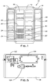
- FIG. 1 shows a typical household refrigerator, indicated generally at 10, comprising a fresh food compartment 12 and a freezer compartment 16.
- a door 14, shown in FIG. 1 as open is mounted to the refrigerator body by hinges and serves to close the front of the fresh food compartment 12 as well as provide access to the interior of the fresh food compartment.
- a door 18, shown in FIG. 1 as open also is mounted to the refrigerator body by hinges and serves to close the front of the freezer compartment 16 as well as provide access to the interior of the freezer compartment.
- the fresh food and freezer compartments can include a variety of shelves 20, closed drawers 22 and basket-like drawers 24 for storing articles of food and the like.
- the refrigerator 10 also incorporates in the fresh food compartment 12 an embodiment 30 of the storage compartment of the invention.
- the storage compartment 30 of the invention is shown and described herein with reference to the incorporation of the storage compartment in the fresh food compartment of a household refrigerator, the compartment can be used in other circumstances such as, for example, in other types of refrigeration appliances and in other types of controlled environments, such as in the freezer compartment of a refrigerator.
- the storage compartment can be used as a self-contained storage compartment outside a controlled environment.
- the storage compartment of the invention can be located in a household kitchen cabinet.
- the storage compartment 30 can be located at virtually any location in the fresh food compartment and more than one storage compartment can be provided.
- the embodiment of the storage compartment of the invention shown in the drawings can have at least two modes of operation as described in more detail in United States Patent Application referred to above.
- gases are evacuated from the storage compartment while the compartment is sealed from the admittance of gases from the exterior of the compartment, whereby the articles being stored in the compartment are stored at a pressure less than the pressure at the exterior of the storage compartment.
- Articles stored in this manner are sometimes said to be stored under vacuum. It will be understood that when the pressure in the storage compartment is less than the pressure at the exterior of the compartment, less oxygen will be present in the compartment so that any deleterious effect of the oxygen on articles stored in the compartment will be mitigated.
- gases are evacuated from the storage compartment while the compartment is open to the admittance of gases from the exterior of the compartment, whereby the articles being stored are ventilated by the gases admitted to the storage compartment.
- the gases admitted will comprise the ambient air.
- the storage compartment can also have a third mode of operation wherein both the first mode of operation and the second mode of operation are rendered inoperative.
- the embodiment of the storage compartment shown in the accompanying drawings can function so that when the articles are stored in the first mode of operation, the storage compartment is operative to intermittently remove additional gases from the compartment, whereby the pressure at which the articles are being stored is maintained at less than the pressure at the exterior of the compartment.
- the removal of additional gases may be required for example because of the infiltration into the storage compartment of the gases or the generation of gases by the articles stored in the storage compartment.
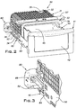
- FIG. 2 One embodiment of the storage compartment 30 of the invention is shown in greater detail in FIG. 2 .
- the storage compartment is shown as removed from the refrigerator 10 but is adapted to be contained within a refrigerator.
- the storage compartment when contained within the fresh food compartment of a refrigerator, can be secured to the interior of the fresh food compartment in any convenient manner familiar to those having ordinary skill in the art.
- the storage compartment 30 is shown in FIG. 2 as open whereby access can be had to the interior of the compartment for the purpose, for example, of placing into or removing from the interior of the storage compartment articles stored in the compartment.
- the storage compartment 30 comprises an external enclosure or housing, indicated generally at 31, and a holding compartment, in the general form of a drawer in the illustrated embodiment and indicated generally at 41, that is adapted to be in gas flow communication with a gas evacuation system further described below for removing gases from the interior of the holding compartment 41.
- the enclosure 31 is referred to as an external enclosure in the sense that the enclosure 31 is external to the holding compartment 41.
- the external enclosure 31 includes an upper wall 32, a bottom wall 34, opposed side walls 36, only one of which can be seen in FIG. 2 , and a rear wall 38.
- the external enclosure 31 also includes an opening 39 at the front of the enclosure by means of which access may be had to the interior of the enclosure.
- a support plate 35 can be attached to the upper wall 32 and a support plate 37 can be attached to the bottom wall 34 to provide rigidity and strength to the external enclosure 31.
- the support plates 35 and 37 can be made of any suitable material such as stainless steel or a rigid plastic for example.
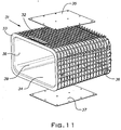
- the holding compartment 41 comprises a front panel 42 and a pan 44, shown in greater detail in FIG. 10 , for holding articles placed within the holding compartment.
- the interior of the pan is adapted to be in air flow communication with the gas evacuation system.
- a forward end 43 of the pan is supported at the front panel 42 while a rearward end 45 of the pan is supported at the interior of the external enclosure 31, more specifically at the interior surface of the bottom wall 34 of the external enclosure.
- the holding compartment 41 is capable of being inserted into the interior of the external enclosure 31 through the opening 39 in the external enclosure, for storing articles contained within the holding compartment, and is capable of being withdrawn from the interior of the external enclosure 31 when access is to be had to the interior of the holding compartment.
- This movement of the holding compartment 41 into and out of the interior of the external enclosure 31 is accomplished by means of complementary surfaces at the holding compartment and at the exterior of the external enclosure that are in engagement with one another and along which the holding compartment travels when it is inserted into and withdrawn from the interior of the external enclosure 31. More specifically, with reference to FIG.
- the complementary surfaces comprise a first component 50 of a sliding rail system that is mounted at the front panel 42 of the holding compartment 41 and a complementary second component 52 of the sliding rail system that is mounted at the exterior of the external enclosure 31.
- a sliding rail system as described is provided at both sides of the front panel 42 and both exterior sides of the external housing although only one is visible in FIG. 2 .
- Sliding rail systems capable of functioning in the described manner are known to those having ordinary skill in the art.
- other types of arrangements can be provided for mounting the holding compartment in relation to the external enclosure in a way that will allow the holding compartment to be conveniently inserted into and withdrawn from the interior of the external enclosure.
- Each of the external enclosure 31 and the holding compartment 41 have a coacting surface that comes closer to the other coacting surface as the holding compartment is inserted further into the interior of the external enclosure.
- a seal 60 is interposed between the coacting surfaces of the external enclosure 31 and the holding compartment 41 for sealing off the interior of the holding compartment to the entry of gases from outside the holding compartment when the holding compartment is inserted into the external enclosure and the coacting surfaces of the external enclosure and the holding compartment are brought together in a sealing relationship with the seal.
- the coacting surface 33 of the external enclosure is located at the front portion of the external enclosure at the perimeter of the opening 39 in the external enclosure as shown in FIG. 2 .
- the back of the front panel is shown as including the coacting surface 40 of the holding compartment 41.
- Threaded holes 75 also are provided at the back of the front panel 42 for securing a respective first component 50 of the sliding rail system at each side of the back of the front panel.
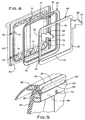
- a bracket 46 is mounted at the back of the front panel 42 using any suitable mounting means.
- openings 70 are provided in the bracket 46 and complementary threaded holes 71 are provided in the front panel whereby the bracket 46 can be mounted to the front panel using screws 73.
- the bracket 46 also includes a support system in the nature of support arms 47 for supporting the forward end 43 of the pan 44. In this connection, the slots 49 at the sides of and towards the front of the pan 44 fit down over the tabs 48 on the support arms 47 to hold the forward end 43 of the pan 44 in place on the bracket 46.
- the bottom of the rearward end 45 of the pan 44 includes a roller system in the form of two wheels 55 that rests at the interior surface of the bottom wall 34 of the external enclosure 31 and supports the rearward end of the pan.
- the bracket 46 also secures the seal, indicated generally at 60, in place at the coacting surface 40 of the front panel 42 so that the seal is mounted at the coacting surface 43 of the front panel 42 as best seen in FIG. 5 .
- the seal 60 is shown as mounted at the coacting surface 40 of the holding compartment 41, the seal can be mounted at either one of the coacting surface 40 of the holding compartment or the coacting surface 33 of the external enclosure 31.
- One way of mounting the seal 60 is best seen in FIG. 5 .
- the seal includes a projection 66 that fits into a slot at the coacting surface 40 and a flange 64 that is arranged at approximately a right angle to the projection 66.
- the bracket 46 bears against the flange 64 when the bracket 46 is secured to the back of the panel 42, and the seal 60 is thereby mounted at the coacting surface 40.
- the seal 60 in addition to the flange 64 and the projection 66, includes a first portion 61 and a second portion 62.
- the first portion 61 and the second portion 62 of the seal 60 are arranged with respect to one another such that the first portion 61 of the seal will come into contact with the one of the coacting surfaces of the external enclosure 31 and the holding compartment 41 at which the seal is not mounted (coacting surface 33 in the embodiment illustrated in the drawings) before the second portion 62 of the seal comes into contact with the one of the coacting surfaces of the external enclosure and the holding compartment at which the seal is not mounted when the holding compartment 41 is inserted into the interior of the external enclosure 31 and the coacting surfaces 33 and 40 of the external enclosure and the holding compartment, respectively, are brought together in a sealing relationship with seal 60.
- the first portion 61 of the seal is more flexible than the second portion 62 of the seal and, as the coacting surfaces of the external enclosure 31 and the holding compartment 41 are brought together in a sealing relationship with the seal 60, the first portion 61 of the seal forms an initial flexible seal between the coacting surfaces of the external enclosure and the holding compartment.
- the second portion of the seal 62 which is heavier and more substantial than the first portion 61 of the seal, forms a more substantial additional seal between the coacting surfaces of the external enclosure and holding compartment as the coacting surfaces of the external enclosure and the holding compartment surfaces are brought closer together as a result of the holding compartment being inserted further into the interior of the external enclosure.
- the first portion 61 of the seal 60 extends away from the coacting surface 40 toward the coacting surface 33 a further distance than the second portion 62 of the seal and, consequently, the first portion 61 of the seal 60 will engage the coacting surface 33 before the second portion 62 of the seal 60.
- the first portion 61 of the seal 60 comprises a web that has an interior end attached at an attachment location 63 to the second portion 62 of the seal and a free end that extends away from the attachment location 63 and the coacting surface 40.
- the first portion 61 of the seal 60 is sufficiently flexible that the free end of the first portion of the seal will flex about the attachment location 63 where the interior end of the web is attached to the second portion of the seal and allow the coacting surface 33 of the external enclosure to come into contact with the second portion 62 of the seal when the coacting surfaces of the external enclosure and the holding compartment continue to be brought closer together as a result of the holding compartment 41 being inserted further into the interior of the external enclosure 31.
- the surface of the second portion 62 of the seal that comes into contact with the coacting surface 33 of the external enclosure 31 is convex.
- the web 61 of the seal is flared in a direction outwardly of the attachment location 43 and forms an acute angle with the second portion 62 of the seal 60 at the attachment location 63, whereby the web engages the coacting surface 33 of the external enclosure 31 at an acute angle.
- the application of the seal 60 is not limited to a storage compartment comprising an external enclosure and a holding compartment but the seal can also be utilized with other structures comprising a storage compartment.
- the seal can be mounted at a coacting surface of a first component of a storage compartment and interposed between the coacting surface of the first component of the storage compartment and a coacting surface of a second component of the storage compartment, the first and second components of the storage compartment being movable with relation to one another such that their coacting surfaces are adapted to be moved together into a sealing relationship along with the seal, whereby gases may be evacuated from the first component of the storage compartment and the pressure in the first component of the storage compartment reduced.
- the seal would include a first portion and a second portion arranged with respect to one another such that the first portion of the seal would come into contact with the coacting surface of the second component of the storage compartment before the second portion of the seal comes into contact with the coacting surface of the second component of the storage compartment when the first component and the second component are brought together in a sealing relationship with the seal.
- the first portion of the seal would be more flexible than the second portion of the seal, whereby, as the coacting surfaces of the first component and the second component of the storage compartment are brought together in a sealing relationship with the seal, the first portion of the seal would form an initial seal between the coacting surfaces of the first component and the second component and the second portion of the seal would form a more substantial additional seal between the coacting surfaces of the first component and the second component as the coacting surfaces of the first component and the second component of the storage compartment are brought closer together.
- the first portion of the seal would comprise a web that has an interior end attached at an attachment location to the second portion of the seal and a free end that extends away from the attachment location and the coacting surface of the first component of the storage compartment at which the seal is mounted.
- the web would be sufficiently flexible that the free end of the web would flex about the attachment location where the interior end of the web is attached to the second portion of the seal and allow the coacting surface of the second component of the storage compartment to come into contact with the second portion of the seal when the coacting surfaces of the first component and the second component of the storage compartment are brought closer together.
- the surface of the second portion of the seal that comes into contact with the coacting surface of the second component of the storage compartment would be convex in one embodiment.
- the interior of the storage compartment 30, including the interior of the holding compartment 41 is adapted to be in gas flow communication with a gas evacuation system for removing gases from the interior of the storage compartment, including the interior of the holding compartment.
- a gas evacuation system is shown in FIG. 6 at 102 as being mounted at the rear surface 38 of the external enclosure 31.
- the gas evacuation system can comprise what is typically referred to as a vacuum pump.
- the gas evacuation system 102 in addition to being in gas flow communication with the interior of the storage compartment 30, is capable of functioning selectively in an active state wherein the gas evacuation system removes gases from the interior of the storage compartment 30, including the holding compartment 41, and in an idle state wherein the gas evacuation system 102 does not remove gases from the interior of the storage compartment including the holding compartment.
- valve arrangement 104 that also is mounted at the rear wall 38 of the external housing 31.
- the valve arrangement 104 can comprise any type of valve known to those of ordinary skill in the art that is capable of functioning in an open state wherein gases from outside the interior of the storage compartment 30 can be admitted through the valve arrangement to the interior of the storage compartment and a closed state wherein gases from outside the interior of the storage compartment 30 are prevented from being admitted to the interior of the storage compartment through the valve arrangement.
- the valve arrangement 104 can comprise a solenoid operated valve in the nature of a pressure release valve.
- the storage compartment 30 can function so that the gas evacuation system 102 can be selectively placed in an active state and the valve arrangement 104 selectively placed in a closed state, whereby gases will be removed from the interior of the storage compartment 30 and the pressure within the interior of the holding compartment 41 reduced to a selected pressure less than the pressure outside the interior of the storage compartment when the interior of the storage compartment is otherwise sealed off from the admittance of gases from outside the storage compartment.
- the storage compartment 30 functions in this manner, the articles stored in the holding compartment 41 will be stored under vacuum wherein less oxygen will be available to react with the stored articles.
- the gas evacuation system 102 additionally, can be selectively placed in an idle state and the valve arrangement 104 can be selectively, concurrently placed in an open state when the interior of the storage compartment 30 is at a pressure below the pressure outside the interior of the storage compartment as described in the preceding paragraph.
- the gases admitted to the interior of the holding compartment 41 through the valve arrangement 104 will cause the pressure within the interior of the storage compartment to increase so that the pressure within the interior of the storage compartment and the pressure outside the interior of the storage compartment will be substantially equalized. This makes it more convenient to access the articles within the holding compartment.
- the gas evacuation system 102 can be selectively placed in an intermittent active state following the reduction of the pressure in the holding compartment 41 to a selected pressure as described above and the valve arrangement 104 placed in a closed state.
- additional gases are intermittently removed from the interior of the holding compartment 41 and the pressure within the interior of the holding compartment is maintained below the pressure at the outside of the storage compartment and the conditions of a vacuum preserved.
- additional gases can be generated, for example, by the articles, such as foodstuffs, stored within the holding compartment.
- the additional gases can comprise ethylene gas given off by fruits and vegetables stored in the holding compartment 41.
- the storage compartment 30 can function as a crisper for fruits and vegetables for example.
- the gas evacuation system 102 is selectively placed in an active state and the valve arrangement 104 placed in an open state, whereby the gases admitted to the interior of the holding compartment 41 through the valve arrangement 104 are ventilated through the interior of the storage compartment.
- the ventilation can provide a variety of salutary effects. For example, humidity can build up in the storage compartment 30 and the excess humidity can be removed by the gas evacuation system 102 while fresh air is admitted to the storage compartment through the valve arrangement 104.
- an electronic-control system including a controller 106, can be provided for controlling the operations of the gas evacuation system 102 and the valve arrangement 104, as those operations have been described above. Any suitable type of controller known in the art may be used.
- the controller 106 can also be located at the rear wall 38 of the external enclosure 31 as shown in FIG. 6 .
- a user interface 57 located at the top wall 32 of the external enclosure 31 near the front of the enclosure, as shown in FIG. 2 is operatively connected to the controller 106 for providing to the controller instructions concerning the operation of the gas evacuation system 102 and the valve arrangement 104 as input to the user interface 57 by a user.
- the user can employ the user interface 57 to switch between the modes of operation of the storage compartment described above by entering an appropriate command into the user interface. More specifically, when the user enters a command into the user interface 57, such as, for example, when the user wishes to store articles in the storage compartment under vacuum, the command is communicated to the controller 106. The controller 106 then processes the command and sends a corresponding signal to the gas evacuation system 102 and the valve arrangement 104. The gas evacuation system and the valve arrangement then function in the mode selected by the user.
- the user enters an appropriate command at the user interface 57 and the controller, in response, will cause the gas evacuation system to be placed in an idle mode and cause the valve arrangement to be opened whereby the pressure within the storage compartment and pressure outside the compartment will be equalized.
- the controller 106 also can be programmed so as to control the functioning of the gas evacuation system and valve arrangement for the purpose of intermittently removing additional gases from the interior of the storage compartment 30 after the compartment has been placed in the vacuum mode.
- the user interface 57 also provides for selectively inputting instructions to the controller 106 for placing each of the gas evacuation system 102 and the valve arrangement 104 in a non-functioning mode whereby the gas evacuation system and the valve arrangement are shut down.
- the controller 106, as well as some or all of the other components shown as mounted to rear wall 38 of the external enclosure 31, can be located elsewhere inside or outside the refrigerator 10.
- the operation of the storage compartment 30 can be supplemented by the inclusion of a latching mechanism for securing the holding compartment 41 to the external enclosure 31 when the coacting surfaces of the holding compartment and the external enclosure are brought together.
- a latching mechanism for securing the holding compartment 41 to the external enclosure 31 when the coacting surfaces of the holding compartment and the external enclosure are brought together.
- An embodiment of such a latching mechanism is shown in the drawings in Figs. 2, 3 , 7, 8 and 9 .
- the function of the latching mechanism is to secure the holding compartment 41 to the external enclosure 31 so as to initially maintain in place the seal 60 sealing off the interior of the holding compartment from the exterior of the external housing.
- the latching mechanism provides the initial force required to seal the holding compartment 41 and the external enclosure 31 together whereby gases are prevented from entering the holding compartment interior.
- the latching mechanism also can function in a manner so as to be inoperative to secure the holding compartment 41 to the external enclosure 31 when the pressure differential between the pressure within the interior of the holding compartment and the pressure at the exterior of the external enclosure is adequate to prevent the holding compartment from becoming disengaged from the external enclosure so as to prevent opening of the seal between the holding compartment 41 and the external enclosure 31.
- the latching mechanism is provided for securing the holding compartment 41 and the external enclosure 31 together when the coacting surfaces 40 and 33 of the holding compartment and the external enclosure, respectively, are first brought together.
- the coacting surfaces along with the seal 60 positioned between the coacting surfaces all come into tight engagement, whereby the coacting surfaces of the holding compartment and the external enclosure are prevented from disengaging and allowing gases from outside the interior of the holding compartment to enter the interior of the holding compartment.
- the latching mechanism functions so as to be disabled from securing the holding compartment 41 and the external enclosure 31 together when the gas evacuation system 102 has removed sufficient gas from the interior portion of the holding compartment to establish a pressure differential between the interior portion of the holding compartment and the exterior of the external enclosure adequate to maintain the drawer and the external enclosure secured together
- the latching mechanism for securing together the external housing 31 and the holding compartment 41 when the coacting surfaces 40 and 33 of the holding compartment and the external housing, respectively, are brought together in a sealing relationship with the seal 60 comprises a fixed retaining element 82 mounted at one of the external enclosure and the holding compartment and a movable latching element 80 mounted at the other one of the external enclosure and the holding compartment.
- the movable latching element 80 is movable between a position where it is free of the fixed retaining element 82 and a position where it is latched to the fixed retaining element.
- the fixed retaining element 82 is mounted at the holding compartment 41 and the movable latching element 80 is mounted at the external enclosure 31. More specifically, in that embodiment, the fixed retaining element 82 is mounted at the first component 50 of the sliding rail system and the movable latching component 80 is mounted at the second component 52 of the sliding rail system.
- the movable latching element comprises a hook-shaped element 86 in which is located an opening 87 as best seen in FIG. 9 .
- the hook-shaped element 86 is movable between a position where the hook-shaped element is free of the fixed retaining element 82 as shown in FIG. 7 and a position where the hook-shaped element 86 is latched to the fixed retaining element 82 as shown in FIG. 8 .
- the hooked portion of the hook-shaped element will be latched down over the dowel 84 of the fixed retaining element 82.
- the movable latching element 80 also includes a driving arrangement that is operatively associated with the hook-shaped element 86 for moving the hook-shaped element between the position where the hook-shaped element is free of the fixed retaining element 82 and the position where the hook-shaped element is latched to the fixed retaining element.
- the hook-shaped element 86 and the driving arrangement for the hook-shaped element are contained within housing 81 of the movable latching mechanism 80.
- the driving arrangement includes a motor 98 that is mounted to the inside of the housing 81 and is behind the hook-shaped element 86 as viewed in FIGs. 7 and 8 .
- the motor has a drive shaft that is attached to a cam 91 by insertion of the drive shaft into the opening 92 in the cam.
- the opening 92 is offset from the center of the cam 91, which is cylindrical in shape, whereby the cam will rotate in an eccentric manner when driven by drive shaft of the motor.
- the cam 91 is located in the opening 87 in the hook-shaped element 86 and as the drive shaft rotates the cam eccentrically within the opening 87, the hook-shaped element 86 will be caused to move between the position where the hook-shaped element is free of the fixed retaining element 82 and the position where the hook-shaped element is latched to the fixed retaining element.
- the movement of the hook-shaped element between the free and latched positions is abetted by a fixed pin 90 attached to the housing 81 and located in a guide slot 89 in the hook-shaped element 86 together with a pin 88 attached to the hook-shaped element 86 and located in a slot 85 in the housing 81. More specifically, when the hook-shaped element moves between the free position of FIG. 7 and the latched position of FIG. 8 , the eccentric rotation of the cam 91 in the opening 87 will force the hook-shaped element rearward or to the right as viewed in FIG. 7 . The concurrent movement of the pin 88 in the slot 85 will allow this rearward movement of the hook-shaped element to take place. At the same time, the fixed pin 90 will move in the guide slot 89.
- the guide slot has a configuration such that the fixed pin 90 and the guide slot cooperatively cause the hook-shaped element 86 to move between the position where the hook-shaped element is free of the fixed retaining element, as shown in FIG. 7 and the position where the hook-shaped element is latched to the dowel 84 of the fixed retaining element 82, as shown in FIG. 8 .
- the motor 98 rotates the drive shaft in the opposite direction, causing the cam 91 to be rotated in the opposite direction and forcing the hook-shaped element forward or to the left as viewed in FIG. 8 .
- the movement of the pin 88 in the slot 85 will allow for the forward movement of the hook-shaped element.
- the interaction between the pin 90 and the guide slot 89 will cause the hook-shaped element to move to the position shown in FIG. 7 and become unlatched from the dowel 84.
- a flange 93 is attached to the cam 91 so as to rotate with the cam, the flange having two contact points 94 and 95.
- Contact point 95 is adapted to contact a control switch 100 when the hook-shaped element 86 is in the position free of the fixed retaining element and the other contact point 94 is adapted to contact the control switch when the hook-shaped element is latched to the fixed retaining element.
- the control switch controls the operation of the motor 98.
- the interaction between the latching mechanism and the controller 106 is as follows.
- the controller 106 activates the latching mechanism by supplying power to the motor 98 whereupon the motor drive shaft is rotated so as to rotate the cam 91 in the opening 87 of the hook-shaped element 86.
- the hook-shaped element 86 is in the attitude shown in FIG. 7 and as the cam 91 rotates, it forces the hook-shaped element to move in a direction away from the fixed latching element 82 and finally assume the rearward position shown in FIG. 8 .
- the latching mechanism continues to secure the holding compartment to the external enclosure 31 until the pressure in the drawer holding compartment reaches a pre-selected level that is adequate for the resulting pressure differential between the pressure within the holding compartment 41 and the pressure at the exterior of the external enclosure 31 to maintain the holding compartment secure to the external enclosure.
- a pre-selected pressure level is reached, as sensed by a pressure sensor for example located within the holding compartment 41, the information is passed on to the controller 106.
- the controller then activates the motor 98 so as to rotate the motor drive shaft in the opposite direction.
- the cam 91 forces the hook-shaped element 86 forward while at the same time the cooperative functioning of the fixed pin 90 and the guide slot 89 moves the hook-shaped element upwardly.
- the hook-shaped element moves from the position shown in FIG. 8 to the position shown in FIG. 7 , whereby the latching mechanism becomes separated, that is, the hook-shaped element 86 becomes disengaged from the dowel 84.
- the opposite contact point 95 on the flange 93 will engage the power switch 100 causing the switch to turn off the motor. Disengaging the latching mechanism in this way allows the user to more quickly access the contents of the holding compartment at a later time as desired.
- Access can be gained to the interior of the holding compartment by the user simply inputting to the user interface 57 directions to allow the valve arrangement 104 to admit gases into the holding compartment interior and equalize the pressure in the holding compartment and the pressure at the outside of the external enclosure. It is not necessary at that time to also disengage the latching mechanism.
- the latching mechanism is not limited to a storage compartment comprising an external enclosure and a holding compartment as described above, but the latching mechanism can also be utilized with other structures comprising a storage compartment.
- the seal can be used to secure a first component and a second component of a storage compartment together, the first component and second component being movable relative to one another. 29.
- the latching mechanism would comprise a fixed retaining element mounted at one of the first component and the second component and a movable latching element mounted at the other one of the first component and the second component.
- the movable latching element would comprise a hook-shaped element in which is located an opening, and the hook-shaped element would be movable between a position where the hook-shaped element is free of the fixed retaining element and a position where the hook-shaped element is latched to the fixed retaining element.
- a driving arrangement would be operatively associated with the hook-shaped element for moving the hook-shaped element between a position where the hook-shaped element is free of the fixed retaining element and a position where the hook-shaped element is latched to the fixed retaining element.
- the driving arrangement would include a motor with a drive shaft attached to a cam located in the opening in the hook-shaped element so as to rotate the cam within the opening in the hook-shaped element and cause the hook-shaped element to move between the position where hook-shaped element is free of the fixed retaining element and the position where the hook-shaped element is latched to the fixed retaining element.
- the latching mechanism would include a fixed pin located in a guide slot in the hook-shaped element, the guide slot having a configuration such that the fixed pin and the guide slot cooperatively assist in causing the hook-shaped element to move between the position where it is free of the fixed retaining element and the position where it is latched to the fixed retaining element.
- a flange could be attached to the cam so as to rotate with the cam, the flange having two contact points, one contact point adapted to contact a control switch when the hook-shaped element is in the position free of the fixed retaining element and the other contact point adapted to contact the control switch when the hook-shaped element is latched to the fixed retaining element.
Landscapes
- Engineering & Computer Science (AREA)
- Chemical & Material Sciences (AREA)
- Combustion & Propulsion (AREA)
- Physics & Mathematics (AREA)
- Mechanical Engineering (AREA)
- Thermal Sciences (AREA)
- General Engineering & Computer Science (AREA)
- Cold Air Circulating Systems And Constructional Details In Refrigerators (AREA)
- Refrigerator Housings (AREA)
- Devices That Are Associated With Refrigeration Equipment (AREA)
- Packages (AREA)
Applications Claiming Priority (2)
| Application Number | Priority Date | Filing Date | Title |
|---|---|---|---|
| US11/758,843 US8052235B2 (en) | 2007-06-06 | 2007-06-06 | Storage compartment |
| PCT/US2008/065193 WO2008154175A2 (en) | 2007-06-06 | 2008-05-30 | Storage compartment |
Publications (2)
| Publication Number | Publication Date |
|---|---|
| EP2153144A2 EP2153144A2 (en) | 2010-02-17 |
| EP2153144B1 true EP2153144B1 (en) | 2016-04-20 |
Family
ID=40094754
Family Applications (1)
| Application Number | Title | Priority Date | Filing Date |
|---|---|---|---|
| EP08769840.3A Not-in-force EP2153144B1 (en) | 2007-06-06 | 2008-05-30 | Storage compartment |
Country Status (11)
| Country | Link |
|---|---|
| US (1) | US8052235B2 (pl) |
| EP (1) | EP2153144B1 (pl) |
| JP (1) | JP5389791B2 (pl) |
| KR (1) | KR101541200B1 (pl) |
| CN (1) | CN101720417B (pl) |
| AU (1) | AU2008262157B2 (pl) |
| BR (1) | BRPI0811969B1 (pl) |
| MX (1) | MX2009013279A (pl) |
| PL (1) | PL2153144T3 (pl) |
| RU (1) | RU2468316C2 (pl) |
| WO (1) | WO2008154175A2 (pl) |
Families Citing this family (39)
| Publication number | Priority date | Publication date | Assignee | Title |
|---|---|---|---|---|
| CN2731373Y (zh) * | 2004-09-06 | 2005-10-05 | 伊莱克斯(中国)电器有限公司 | 一种保鲜果菜盒 |
| US20090211202A1 (en) * | 2008-02-27 | 2009-08-27 | Lemme Anthony R | Vacuum or pressure storage system for food or beverage containers |
| DE102009046766A1 (de) * | 2009-11-17 | 2011-06-30 | BSH Bosch und Siemens Hausgeräte GmbH, 81739 | Kältegerät mit einem evakuierbaren Schubfach |
| CN102261785B (zh) * | 2010-05-28 | 2015-06-03 | 博西华家用电器有限公司 | 用于制冷器具的低压储物单元以及制冷器具 |
| CN102261794B (zh) * | 2010-05-28 | 2015-08-26 | 博西华家用电器有限公司 | 家用电器 |
| KR20130116741A (ko) * | 2012-04-16 | 2013-10-24 | 엘지전자 주식회사 | 냉장고의 야채실 박스 밀폐구조 |
| CN103542669B (zh) | 2012-07-13 | 2018-06-12 | 博西华电器(江苏)有限公司 | 具有储藏单元的制冷器具 |
| KR101932047B1 (ko) * | 2012-07-17 | 2019-03-20 | 엘지전자 주식회사 | 결로 저감을 위한 냉장고 야채실 및 이를 구비한 냉장고, 냉장고 야채실의 결로저감방법 |
| US9121633B2 (en) | 2012-07-23 | 2015-09-01 | Lg Electronics Inc. | Refrigerator |
| KR101918059B1 (ko) * | 2012-07-23 | 2018-11-13 | 엘지전자 주식회사 | 드로어 밀폐유지장치를 구비한 냉장고 |
| KR101971228B1 (ko) * | 2012-07-23 | 2019-04-22 | 엘지전자 주식회사 | 감압실을 구비한 냉장고 |
| KR101918060B1 (ko) * | 2012-07-24 | 2018-11-13 | 엘지전자 주식회사 | 드로어 밀폐유지장치를 구비한 냉장고 |
| EP2690387B1 (en) * | 2012-07-26 | 2020-09-02 | LG Electronics Inc. -1- | Refrigerator vegetable room |
| KR101932048B1 (ko) * | 2012-07-26 | 2019-03-20 | 엘지전자 주식회사 | 온도 분포 개선을 위해 금속판을 이용한 냉장고 야채실 및 이를 구비한 냉장고 |
| KR101918061B1 (ko) * | 2012-07-26 | 2018-11-13 | 엘지전자 주식회사 | 온도 분포 개선을 위해 단열재 및 금속판을 이용한 냉장고 야채실 및 이를 구비한 냉장고 |
| KR101398460B1 (ko) * | 2012-09-18 | 2014-05-27 | 엘지전자 주식회사 | 야채실 드로워에 밀폐유지장치를 구비한 냉장고 |
| CN203231607U (zh) * | 2012-12-20 | 2013-10-09 | 博西华电器(江苏)有限公司 | 具有真空系统的冰箱 |
| KR102068179B1 (ko) | 2013-05-28 | 2020-01-20 | 엘지전자 주식회사 | 냉장고용 야채실 및 이를 구비한 냉장고 |
| KR102042220B1 (ko) * | 2013-05-28 | 2019-11-07 | 엘지전자 주식회사 | 냉장고용 야채실 및 이를 구비한 냉장고 |
| KR102141047B1 (ko) | 2013-05-28 | 2020-08-04 | 엘지전자 주식회사 | 냉장고용 야채실 및 이를 구비한 냉장고 |
| EP2808628B1 (en) * | 2013-05-28 | 2016-07-20 | LG Electronics Inc. | Vegetable container for refrigerators and refrigerator having the same |
| KR102104439B1 (ko) | 2013-05-28 | 2020-04-24 | 엘지전자 주식회사 | 냉장고용 야채실 및 이를 구비한 냉장고 |
| EP2808630B1 (en) | 2013-05-28 | 2019-08-21 | LG Electronics Inc. -1- | Airtight container for refrigerator and refrigerator including the same |
| CA2868193A1 (en) * | 2013-10-23 | 2015-04-23 | Advantage Pharmacy Services Llc | Solenoid-driven latch and ejector device |
| KR102184537B1 (ko) * | 2014-01-28 | 2020-11-30 | 엘지전자 주식회사 | 냉장고용 야채실 및 이를 구비한 냉장고 |
| CN105466132B (zh) * | 2014-07-16 | 2019-04-23 | 博西华电器(江苏)有限公司 | 真空储藏单元及包括该真空储藏单元的制冷设备 |
| US9523530B2 (en) * | 2015-04-14 | 2016-12-20 | Electrolux Home Products, Inc. | Removable freezer door |
| JP6543132B2 (ja) * | 2015-08-07 | 2019-07-10 | 日立グローバルライフソリューションズ株式会社 | 冷蔵庫 |
| US9903637B1 (en) * | 2017-03-16 | 2018-02-27 | Electrolux Home Products, Inc. | Container system for a cabinet |
| KR102330783B1 (ko) | 2017-06-01 | 2021-11-25 | 엘지전자 주식회사 | 냉장고 |
| KR102511095B1 (ko) | 2017-12-13 | 2023-03-16 | 엘지전자 주식회사 | 진공단열체 및 냉장고 |
| KR102466448B1 (ko) | 2017-12-13 | 2022-11-11 | 엘지전자 주식회사 | 진공단열체 및 냉장고 |
| KR102568737B1 (ko) | 2017-12-13 | 2023-08-21 | 엘지전자 주식회사 | 진공단열체 및 냉장고 |
| KR102466446B1 (ko) * | 2017-12-13 | 2022-11-11 | 엘지전자 주식회사 | 진공단열체 및 냉장고 |
| KR102530909B1 (ko) | 2017-12-13 | 2023-05-11 | 엘지전자 주식회사 | 진공단열체 및 냉장고 |
| CN108895757B (zh) * | 2018-08-08 | 2024-03-29 | 惠而浦(中国)股份有限公司 | 一种真空保鲜装置 |
| IL268079B (en) * | 2019-07-15 | 2020-11-30 | Oren Naim | Vacuum chamber system |
| DE102019124058B3 (de) * | 2019-09-09 | 2020-11-12 | Accuride International Gmbh | Gerät zur Reinigung, Lagerung oder Garung von Gegenständen |
| CN117109239B (zh) * | 2022-05-16 | 2025-10-03 | 海信冰箱有限公司 | 冰箱 |
Family Cites Families (50)
| Publication number | Priority date | Publication date | Assignee | Title |
|---|---|---|---|---|
| US2425816A (en) | 1944-07-13 | 1947-08-19 | W L Maxson Corp | Apparatus for cooling under ultraviolet radiation and vacuum conditions |
| US2894845A (en) * | 1955-04-18 | 1959-07-14 | Gen Electric | Methods of preserving fresh foods |
| US3217921A (en) * | 1962-02-21 | 1965-11-16 | Gen Tire & Rubber Co | Sealing device |
| US3216214A (en) | 1963-05-21 | 1965-11-09 | Breconvuot Anstalt | Vacuum generation apparatus with closed fluid circuit ejector system, especially for vacuum generation of home refrigerator cells and the like |
| US4615178A (en) | 1984-12-10 | 1986-10-07 | Stanley Badenhop | Apparatus and method for controlling a vacuum cooler |
| US5040856A (en) * | 1987-02-27 | 1991-08-20 | Sub-Zero Freezer Company, Inc. | Comestible storage compartment for refrigeration unit |
| US4829653A (en) * | 1987-03-19 | 1989-05-16 | General Electric Company | Method of making an appliance door having a module support system |
| IT1230958B (it) | 1989-06-30 | 1991-11-08 | Eurodomestici Ind Riunite | Frigorifero, congelatore o similare con contenitore amovibile in cui e' realizzato il vuoto. |
| DE3924589C1 (pl) | 1989-07-25 | 1990-12-20 | Bosch-Siemens Hausgeraete Gmbh, 8000 Muenchen, De | |
| FR2651873B1 (fr) | 1989-09-11 | 1992-02-28 | Air Liquide | Refrigerateur domestique equipe de moyens pour la conservation de fruits et legumes sous atmosphere appauvrie en oxygene. |
| IT1238452B (it) * | 1990-02-01 | 1993-08-18 | Eurodomestici Ind Riunite | Frigorifero, congelatore o similare con contenitore amovibile in cui e' realizzato il vuoto a chiusura ed apertura automatica |
| US5271240A (en) | 1992-07-06 | 1993-12-21 | Arex, Inc. | Household refrigerator-freezer cooling apparatus with vacuum as the preserving means |
| US5551775A (en) * | 1994-02-22 | 1996-09-03 | Accuride International, Inc. | Telescopic drawer slide with mechanical sequencing latch |
| US5946919A (en) | 1997-05-02 | 1999-09-07 | Sharper Image Corp. | Food conservator system |
| CN2295971Y (zh) * | 1997-05-05 | 1998-10-28 | 回世昌 | 电冰箱用真空保鲜箱 |
| US6148875A (en) * | 1997-06-18 | 2000-11-21 | Breen; James | Vacuum food storage system |
| US6166353A (en) * | 1997-08-22 | 2000-12-26 | White Consolidated Industries, Inc. | Free-standing warmer drawer |
| US6170276B1 (en) * | 1999-02-26 | 2001-01-09 | Maytag Corporation | High performance food storage system for a refrigerator |
| US6612116B2 (en) * | 1999-02-26 | 2003-09-02 | Maytag Corporation | Thermoelectric temperature controlled refrigerator food storage compartment |
| JP3871474B2 (ja) * | 1999-08-06 | 2007-01-24 | 株式会社東芝 | 貯蔵庫の扉装置 |
| US6090422A (en) | 1999-08-11 | 2000-07-18 | Taragan; Arie | Refrigerator with automatic vacuum compartment and method of preserving fresh food items using the same |
| WO2001071263A1 (en) | 2000-03-20 | 2001-09-27 | Mo-El S.R.L. | Device and method for the preservation of foods under vacuum |
| US6315336B1 (en) * | 2000-05-30 | 2001-11-13 | Summit Manufacturing, Inc. | Motorized self-cleaning oven latch |
| US6511138B1 (en) | 2000-11-20 | 2003-01-28 | Lionville Systems, Inc. | Drawer closing and latching system |
| US20020083724A1 (en) | 2000-12-28 | 2002-07-04 | Tarlow Kenneth A. | Food storage and preservation system |
| ITMI20010472A1 (it) * | 2001-03-07 | 2002-09-07 | Ilpea Ind Spa | Insieme di tenuta migliorato per mobili frigoriferi e simili con profilo di materia plastica |
| RU2276759C2 (ru) * | 2001-03-13 | 2006-05-20 | Эпплайд Дизайн Энд Инжиниринг Лимитед | Холодильная камера (варианты) |
| US6598517B1 (en) | 2002-03-01 | 2003-07-29 | Mccausland Richard | Vacuum cabinet device |
| KR100827777B1 (ko) * | 2002-04-24 | 2008-05-07 | 엘지전자 주식회사 | 냉장고의 야채실 개폐구조 |
| DE10248510A1 (de) | 2002-10-17 | 2004-04-29 | BSH Bosch und Siemens Hausgeräte GmbH | Kältegerät mit einem evakuierbaren Lagerfach |
| KR20040046245A (ko) * | 2002-11-26 | 2004-06-05 | 엘지전자 주식회사 | 냉장고의 냉기유출 방지구조 |
| JP2004251598A (ja) * | 2003-02-21 | 2004-09-09 | Toshiba Corp | 冷蔵庫 |
| JP2005048978A (ja) * | 2003-07-29 | 2005-02-24 | Toshiba Corp | 冷蔵庫 |
| KR20050026605A (ko) | 2003-09-09 | 2005-03-15 | 삼성전자주식회사 | 진공조리장치 및 그 조리방법 |
| CA2548978A1 (en) | 2003-12-10 | 2005-06-23 | Electrolux Home Products Corporation N.V. | Refrigerating or freezing apparatus with vacuum compartment |
| KR100577422B1 (ko) * | 2003-12-11 | 2006-05-08 | 삼성전자주식회사 | 저장고 |
| US6971418B2 (en) | 2004-01-05 | 2005-12-06 | De Costa John D | Vacuum operable container for storing food |
| JP4027325B2 (ja) * | 2004-01-08 | 2007-12-26 | シャープ株式会社 | 加熱調理器 |
| US7325409B2 (en) * | 2004-03-24 | 2008-02-05 | Espinosa Edward P | Vacuum storage apparatus with sliding drawers |
| GB2414064B (en) | 2004-05-13 | 2007-08-15 | Cambridge Consultants | Vacuum storage compartment construction in cooling apparatus |
| GB2414065B (en) | 2004-05-13 | 2007-08-22 | Cambridge Consultants | Vacuum storage compartment construction in cooling apparatus |
| JP2005351580A (ja) * | 2004-06-11 | 2005-12-22 | Toshiba Corp | 冷蔵庫 |
| US7156428B2 (en) * | 2004-07-02 | 2007-01-02 | France/Scott Fetzer Company | Single switch springless oven door latch assembly |
| US7331163B2 (en) | 2004-10-29 | 2008-02-19 | Hau Joseph A | Refrigerator with integral vacuum sealer |
| ITVA20050010U1 (it) * | 2005-04-07 | 2006-10-08 | Whirlpool Co | Struttura a cassetto refrigerato |
| JP2006308265A (ja) * | 2005-05-02 | 2006-11-09 | Toshiba Corp | 冷蔵庫 |
| US7334823B2 (en) * | 2006-05-05 | 2008-02-26 | Emerson Electric Co.. | Motorized oven lock having a reciprocating latch |
| KR100727670B1 (ko) * | 2006-08-04 | 2007-06-13 | 엘지전자 주식회사 | 수납장이 구비되는 냉장고 |
| JP2008292101A (ja) * | 2007-05-28 | 2008-12-04 | Hitachi Appliances Inc | 冷凍冷蔵庫 |
| US8979621B2 (en) * | 2007-06-05 | 2015-03-17 | Electrolux Home Products, Inc. | Storage systems |
-
2007
- 2007-06-06 US US11/758,843 patent/US8052235B2/en not_active Expired - Fee Related
-
2008
- 2008-05-30 RU RU2009148769/13A patent/RU2468316C2/ru not_active IP Right Cessation
- 2008-05-30 WO PCT/US2008/065193 patent/WO2008154175A2/en not_active Ceased
- 2008-05-30 BR BRPI0811969A patent/BRPI0811969B1/pt not_active IP Right Cessation
- 2008-05-30 KR KR1020107000099A patent/KR101541200B1/ko not_active Expired - Fee Related
- 2008-05-30 JP JP2010511255A patent/JP5389791B2/ja not_active Expired - Fee Related
- 2008-05-30 AU AU2008262157A patent/AU2008262157B2/en not_active Ceased
- 2008-05-30 CN CN2008800229174A patent/CN101720417B/zh not_active Expired - Fee Related
- 2008-05-30 EP EP08769840.3A patent/EP2153144B1/en not_active Not-in-force
- 2008-05-30 PL PL08769840.3T patent/PL2153144T3/pl unknown
- 2008-05-30 MX MX2009013279A patent/MX2009013279A/es active IP Right Grant
Also Published As
| Publication number | Publication date |
|---|---|
| MX2009013279A (es) | 2010-04-21 |
| BRPI0811969A2 (pt) | 2014-11-11 |
| KR101541200B1 (ko) | 2015-07-31 |
| RU2468316C2 (ru) | 2012-11-27 |
| AU2008262157A1 (en) | 2008-12-18 |
| PL2153144T3 (pl) | 2016-12-30 |
| KR20100043174A (ko) | 2010-04-28 |
| WO2008154175A2 (en) | 2008-12-18 |
| BRPI0811969B1 (pt) | 2019-08-13 |
| RU2009148769A (ru) | 2011-07-20 |
| CN101720417A (zh) | 2010-06-02 |
| EP2153144A2 (en) | 2010-02-17 |
| WO2008154175A3 (en) | 2009-10-22 |
| JP5389791B2 (ja) | 2014-01-15 |
| US8052235B2 (en) | 2011-11-08 |
| CN101720417B (zh) | 2012-10-03 |
| JP2010529405A (ja) | 2010-08-26 |
| AU2008262157B2 (en) | 2011-09-01 |
| US20080302441A1 (en) | 2008-12-11 |
Similar Documents
| Publication | Publication Date | Title |
|---|---|---|
| EP2153144B1 (en) | Storage compartment | |
| US9791159B2 (en) | Storage systems | |
| EP1706688B1 (en) | Refrigerating or freezing apparatus with vacuum compartment | |
| EP2650630B1 (en) | Refrigerator | |
| RU2484392C1 (ru) | Холодильник | |
| US20100236279A1 (en) | Refrigerator | |
| US20060131324A1 (en) | Dispenser for refrigerator | |
| KR101643642B1 (ko) | 냉장고 | |
| CN111649515B (zh) | 一种制冷设备 | |
| KR101578354B1 (ko) | 냉장고 도어 개폐장치 | |
| US20070169504A1 (en) | Damper assembly | |
| EP4321826A1 (en) | Refrigerator | |
| JP2008045846A (ja) | 冷蔵庫 | |
| KR19990033606A (ko) | 진공냉장실이 구비된 냉장고 | |
| US20230332823A1 (en) | Refrigerator | |
| KR20090006505U (ko) | 냉장고 | |
| CN221630095U (zh) | 一种制冷器具 | |
| KR20250033902A (ko) | 냉장고 | |
| KR20250033901A (ko) | 냉장고 | |
| KR20070113414A (ko) | 냉장고 | |
| KR19980028647U (ko) | 냉장고 | |
| JP2003083653A (ja) | 冷蔵庫内の製氷部分への給水容器 | |
| KR20000016670U (ko) | 냉장고의 온도조절장치 |
Legal Events
| Date | Code | Title | Description |
|---|---|---|---|
| PUAI | Public reference made under article 153(3) epc to a published international application that has entered the european phase |
Free format text: ORIGINAL CODE: 0009012 |
|
| 17P | Request for examination filed |
Effective date: 20091218 |
|
| AK | Designated contracting states |
Kind code of ref document: A2 Designated state(s): AT BE BG CH CY CZ DE DK EE ES FI FR GB GR HR HU IE IS IT LI LT LU LV MC MT NL NO PL PT RO SE SI SK TR |
|
| AX | Request for extension of the european patent |
Extension state: AL BA MK RS |
|
| DAX | Request for extension of the european patent (deleted) | ||
| RAP1 | Party data changed (applicant data changed or rights of an application transferred) |
Owner name: ELECTROLUX HOME PRODUCTS, INC. |
|
| 17Q | First examination report despatched |
Effective date: 20150225 |
|
| GRAP | Despatch of communication of intention to grant a patent |
Free format text: ORIGINAL CODE: EPIDOSNIGR1 |
|
| INTG | Intention to grant announced |
Effective date: 20151113 |
|
| GRAS | Grant fee paid |
Free format text: ORIGINAL CODE: EPIDOSNIGR3 |
|
| GRAA | (expected) grant |
Free format text: ORIGINAL CODE: 0009210 |
|
| AK | Designated contracting states |
Kind code of ref document: B1 Designated state(s): AT BE BG CH CY CZ DE DK EE ES FI FR GB GR HR HU IE IS IT LI LT LU LV MC MT NL NO PL PT RO SE SI SK TR |
|
| REG | Reference to a national code |
Ref country code: GB Ref legal event code: FG4D |
|
| REG | Reference to a national code |
Ref country code: CH Ref legal event code: EP |
|
| REG | Reference to a national code |
Ref country code: AT Ref legal event code: REF Ref document number: 792911 Country of ref document: AT Kind code of ref document: T Effective date: 20160515 |
|
| REG | Reference to a national code |
Ref country code: IE Ref legal event code: FG4D |
|
| REG | Reference to a national code |
Ref country code: FR Ref legal event code: PLFP Year of fee payment: 9 |
|
| REG | Reference to a national code |
Ref country code: DE Ref legal event code: R096 Ref document number: 602008043731 Country of ref document: DE |
|
| REG | Reference to a national code |
Ref country code: LT Ref legal event code: MG4D |
|
| PG25 | Lapsed in a contracting state [announced via postgrant information from national office to epo] |
Ref country code: BE Free format text: LAPSE BECAUSE OF NON-PAYMENT OF DUE FEES Effective date: 20160531 |
|
| REG | Reference to a national code |
Ref country code: AT Ref legal event code: MK05 Ref document number: 792911 Country of ref document: AT Kind code of ref document: T Effective date: 20160420 |
|
| REG | Reference to a national code |
Ref country code: NL Ref legal event code: MP Effective date: 20160420 |
|
| PG25 | Lapsed in a contracting state [announced via postgrant information from national office to epo] |
Ref country code: NO Free format text: LAPSE BECAUSE OF FAILURE TO SUBMIT A TRANSLATION OF THE DESCRIPTION OR TO PAY THE FEE WITHIN THE PRESCRIBED TIME-LIMIT Effective date: 20160720 Ref country code: LT Free format text: LAPSE BECAUSE OF FAILURE TO SUBMIT A TRANSLATION OF THE DESCRIPTION OR TO PAY THE FEE WITHIN THE PRESCRIBED TIME-LIMIT Effective date: 20160420 Ref country code: FI Free format text: LAPSE BECAUSE OF FAILURE TO SUBMIT A TRANSLATION OF THE DESCRIPTION OR TO PAY THE FEE WITHIN THE PRESCRIBED TIME-LIMIT Effective date: 20160420 Ref country code: NL Free format text: LAPSE BECAUSE OF FAILURE TO SUBMIT A TRANSLATION OF THE DESCRIPTION OR TO PAY THE FEE WITHIN THE PRESCRIBED TIME-LIMIT Effective date: 20160420 |
|
| PG25 | Lapsed in a contracting state [announced via postgrant information from national office to epo] |
Ref country code: PT Free format text: LAPSE BECAUSE OF FAILURE TO SUBMIT A TRANSLATION OF THE DESCRIPTION OR TO PAY THE FEE WITHIN THE PRESCRIBED TIME-LIMIT Effective date: 20160822 Ref country code: AT Free format text: LAPSE BECAUSE OF FAILURE TO SUBMIT A TRANSLATION OF THE DESCRIPTION OR TO PAY THE FEE WITHIN THE PRESCRIBED TIME-LIMIT Effective date: 20160420 Ref country code: LV Free format text: LAPSE BECAUSE OF FAILURE TO SUBMIT A TRANSLATION OF THE DESCRIPTION OR TO PAY THE FEE WITHIN THE PRESCRIBED TIME-LIMIT Effective date: 20160420 Ref country code: GR Free format text: LAPSE BECAUSE OF FAILURE TO SUBMIT A TRANSLATION OF THE DESCRIPTION OR TO PAY THE FEE WITHIN THE PRESCRIBED TIME-LIMIT Effective date: 20160721 Ref country code: ES Free format text: LAPSE BECAUSE OF FAILURE TO SUBMIT A TRANSLATION OF THE DESCRIPTION OR TO PAY THE FEE WITHIN THE PRESCRIBED TIME-LIMIT Effective date: 20160420 Ref country code: HR Free format text: LAPSE BECAUSE OF FAILURE TO SUBMIT A TRANSLATION OF THE DESCRIPTION OR TO PAY THE FEE WITHIN THE PRESCRIBED TIME-LIMIT Effective date: 20160420 Ref country code: SE Free format text: LAPSE BECAUSE OF FAILURE TO SUBMIT A TRANSLATION OF THE DESCRIPTION OR TO PAY THE FEE WITHIN THE PRESCRIBED TIME-LIMIT Effective date: 20160420 |
|
| PG25 | Lapsed in a contracting state [announced via postgrant information from national office to epo] |
Ref country code: BE Free format text: LAPSE BECAUSE OF FAILURE TO SUBMIT A TRANSLATION OF THE DESCRIPTION OR TO PAY THE FEE WITHIN THE PRESCRIBED TIME-LIMIT Effective date: 20160420 |
|
| REG | Reference to a national code |
Ref country code: CH Ref legal event code: PL |
|
| REG | Reference to a national code |
Ref country code: DE Ref legal event code: R097 Ref document number: 602008043731 Country of ref document: DE |
|
| PG25 | Lapsed in a contracting state [announced via postgrant information from national office to epo] |
Ref country code: EE Free format text: LAPSE BECAUSE OF FAILURE TO SUBMIT A TRANSLATION OF THE DESCRIPTION OR TO PAY THE FEE WITHIN THE PRESCRIBED TIME-LIMIT Effective date: 20160420 Ref country code: CZ Free format text: LAPSE BECAUSE OF FAILURE TO SUBMIT A TRANSLATION OF THE DESCRIPTION OR TO PAY THE FEE WITHIN THE PRESCRIBED TIME-LIMIT Effective date: 20160420 Ref country code: SK Free format text: LAPSE BECAUSE OF FAILURE TO SUBMIT A TRANSLATION OF THE DESCRIPTION OR TO PAY THE FEE WITHIN THE PRESCRIBED TIME-LIMIT Effective date: 20160420 Ref country code: RO Free format text: LAPSE BECAUSE OF FAILURE TO SUBMIT A TRANSLATION OF THE DESCRIPTION OR TO PAY THE FEE WITHIN THE PRESCRIBED TIME-LIMIT Effective date: 20160420 Ref country code: DK Free format text: LAPSE BECAUSE OF FAILURE TO SUBMIT A TRANSLATION OF THE DESCRIPTION OR TO PAY THE FEE WITHIN THE PRESCRIBED TIME-LIMIT Effective date: 20160420 Ref country code: LI Free format text: LAPSE BECAUSE OF NON-PAYMENT OF DUE FEES Effective date: 20160531 Ref country code: CH Free format text: LAPSE BECAUSE OF NON-PAYMENT OF DUE FEES Effective date: 20160531 Ref country code: MC Free format text: LAPSE BECAUSE OF FAILURE TO SUBMIT A TRANSLATION OF THE DESCRIPTION OR TO PAY THE FEE WITHIN THE PRESCRIBED TIME-LIMIT Effective date: 20160420 |
|
| REG | Reference to a national code |
Ref country code: IE Ref legal event code: MM4A |
|
| PLBE | No opposition filed within time limit |
Free format text: ORIGINAL CODE: 0009261 |
|
| STAA | Information on the status of an ep patent application or granted ep patent |
Free format text: STATUS: NO OPPOSITION FILED WITHIN TIME LIMIT |
|
| 26N | No opposition filed |
Effective date: 20170123 |
|
| REG | Reference to a national code |
Ref country code: FR Ref legal event code: PLFP Year of fee payment: 10 |
|
| PG25 | Lapsed in a contracting state [announced via postgrant information from national office to epo] |
Ref country code: IE Free format text: LAPSE BECAUSE OF NON-PAYMENT OF DUE FEES Effective date: 20160530 Ref country code: SI Free format text: LAPSE BECAUSE OF FAILURE TO SUBMIT A TRANSLATION OF THE DESCRIPTION OR TO PAY THE FEE WITHIN THE PRESCRIBED TIME-LIMIT Effective date: 20160420 |
|
| PGFP | Annual fee paid to national office [announced via postgrant information from national office to epo] |
Ref country code: PL Payment date: 20170421 Year of fee payment: 10 |
|
| REG | Reference to a national code |
Ref country code: FR Ref legal event code: PLFP Year of fee payment: 11 |
|
| PG25 | Lapsed in a contracting state [announced via postgrant information from national office to epo] |
Ref country code: HU Free format text: LAPSE BECAUSE OF FAILURE TO SUBMIT A TRANSLATION OF THE DESCRIPTION OR TO PAY THE FEE WITHIN THE PRESCRIBED TIME-LIMIT; INVALID AB INITIO Effective date: 20080530 Ref country code: CY Free format text: LAPSE BECAUSE OF FAILURE TO SUBMIT A TRANSLATION OF THE DESCRIPTION OR TO PAY THE FEE WITHIN THE PRESCRIBED TIME-LIMIT Effective date: 20160420 |
|
| PG25 | Lapsed in a contracting state [announced via postgrant information from national office to epo] |
Ref country code: IS Free format text: LAPSE BECAUSE OF FAILURE TO SUBMIT A TRANSLATION OF THE DESCRIPTION OR TO PAY THE FEE WITHIN THE PRESCRIBED TIME-LIMIT Effective date: 20160420 Ref country code: MT Free format text: LAPSE BECAUSE OF NON-PAYMENT OF DUE FEES Effective date: 20160531 Ref country code: LU Free format text: LAPSE BECAUSE OF NON-PAYMENT OF DUE FEES Effective date: 20160530 Ref country code: TR Free format text: LAPSE BECAUSE OF FAILURE TO SUBMIT A TRANSLATION OF THE DESCRIPTION OR TO PAY THE FEE WITHIN THE PRESCRIBED TIME-LIMIT Effective date: 20160420 |
|
| PG25 | Lapsed in a contracting state [announced via postgrant information from national office to epo] |
Ref country code: BG Free format text: LAPSE BECAUSE OF FAILURE TO SUBMIT A TRANSLATION OF THE DESCRIPTION OR TO PAY THE FEE WITHIN THE PRESCRIBED TIME-LIMIT Effective date: 20160420 |
|
| PG25 | Lapsed in a contracting state [announced via postgrant information from national office to epo] |
Ref country code: PL Free format text: LAPSE BECAUSE OF NON-PAYMENT OF DUE FEES Effective date: 20180530 |
|
| PGFP | Annual fee paid to national office [announced via postgrant information from national office to epo] |
Ref country code: IT Payment date: 20220524 Year of fee payment: 15 Ref country code: GB Payment date: 20220520 Year of fee payment: 15 Ref country code: FR Payment date: 20220523 Year of fee payment: 15 Ref country code: DE Payment date: 20220519 Year of fee payment: 15 |
|
| REG | Reference to a national code |
Ref country code: DE Ref legal event code: R119 Ref document number: 602008043731 Country of ref document: DE |
|
| GBPC | Gb: european patent ceased through non-payment of renewal fee |
Effective date: 20230530 |
|
| PG25 | Lapsed in a contracting state [announced via postgrant information from national office to epo] |
Ref country code: IT Free format text: LAPSE BECAUSE OF NON-PAYMENT OF DUE FEES Effective date: 20230530 Ref country code: DE Free format text: LAPSE BECAUSE OF NON-PAYMENT OF DUE FEES Effective date: 20231201 Ref country code: GB Free format text: LAPSE BECAUSE OF NON-PAYMENT OF DUE FEES Effective date: 20230530 |
|
| PG25 | Lapsed in a contracting state [announced via postgrant information from national office to epo] |
Ref country code: FR Free format text: LAPSE BECAUSE OF NON-PAYMENT OF DUE FEES Effective date: 20230531 |