EP2148190A2 - Vorrichtung zur Messung der Ausrichtung des Verhältnisses zwischen benachbarten Körnern anhand eines Winkelmessers in einem Übertragungselektronenmikroskop und Verfahren zum Aufzeigen der Eigenschaften von Korngrenzen - Google Patents
Vorrichtung zur Messung der Ausrichtung des Verhältnisses zwischen benachbarten Körnern anhand eines Winkelmessers in einem Übertragungselektronenmikroskop und Verfahren zum Aufzeigen der Eigenschaften von Korngrenzen Download PDFInfo
- Publication number
- EP2148190A2 EP2148190A2 EP08021545A EP08021545A EP2148190A2 EP 2148190 A2 EP2148190 A2 EP 2148190A2 EP 08021545 A EP08021545 A EP 08021545A EP 08021545 A EP08021545 A EP 08021545A EP 2148190 A2 EP2148190 A2 EP 2148190A2
- Authority
- EP
- European Patent Office
- Prior art keywords
- axis
- axes
- crystal
- tilt
- relationship
- Prior art date
- Legal status (The legal status is an assumption and is not a legal conclusion. Google has not performed a legal analysis and makes no representation as to the accuracy of the status listed.)
- Withdrawn
Links
Images




Classifications
-
- H—ELECTRICITY
- H01—ELECTRIC ELEMENTS
- H01J—ELECTRIC DISCHARGE TUBES OR DISCHARGE LAMPS
- H01J37/00—Discharge tubes with provision for introducing objects or material to be exposed to the discharge, e.g. for the purpose of examination or processing thereof
- H01J37/26—Electron or ion microscopes; Electron or ion diffraction tubes
- H01J37/28—Electron or ion microscopes; Electron or ion diffraction tubes with scanning beams
-
- G—PHYSICS
- G01—MEASURING; TESTING
- G01N—INVESTIGATING OR ANALYSING MATERIALS BY DETERMINING THEIR CHEMICAL OR PHYSICAL PROPERTIES
- G01N23/00—Investigating or analysing materials by the use of wave or particle radiation, e.g. X-rays or neutrons, not covered by groups G01N3/00 – G01N17/00, G01N21/00 or G01N22/00
- G01N23/02—Investigating or analysing materials by the use of wave or particle radiation, e.g. X-rays or neutrons, not covered by groups G01N3/00 – G01N17/00, G01N21/00 or G01N22/00 by transmitting the radiation through the material
-
- G—PHYSICS
- G01—MEASURING; TESTING
- G01N—INVESTIGATING OR ANALYSING MATERIALS BY DETERMINING THEIR CHEMICAL OR PHYSICAL PROPERTIES
- G01N29/00—Investigating or analysing materials by the use of ultrasonic, sonic or infrasonic waves; Visualisation of the interior of objects by transmitting ultrasonic or sonic waves through the object
-
- H—ELECTRICITY
- H01—ELECTRIC ELEMENTS
- H01J—ELECTRIC DISCHARGE TUBES OR DISCHARGE LAMPS
- H01J37/00—Discharge tubes with provision for introducing objects or material to be exposed to the discharge, e.g. for the purpose of examination or processing thereof
- H01J37/02—Details
- H01J37/20—Means for supporting or positioning the object or the material; Means for adjusting diaphragms or lenses associated with the support
-
- H—ELECTRICITY
- H01—ELECTRIC ELEMENTS
- H01J—ELECTRIC DISCHARGE TUBES OR DISCHARGE LAMPS
- H01J2237/00—Discharge tubes exposing object to beam, e.g. for analysis treatment, etching, imaging
- H01J2237/20—Positioning, supporting, modifying or maintaining the physical state of objects being observed or treated
- H01J2237/202—Movement
- H01J2237/20207—Tilt
Definitions
- the present invention relates to an apparatus for measuring the orientation relationship between neighboring grains and a method for revealing the characteristics of grain boundaries using the same, and more particularly, to an apparatus for measuring the orientation relationship between neighboring grains using a goniometer in a transmission electron microscope and a method for revealing the characteristics of grain boundaries by using the apparatus.
- a transmission electron microscope is a device that allows the observation of a crystal structure or a crystal defect with the interference between the transmitted electrons and the diffracted electrons caused by the incidence of electron beam into a few nm thick of specimen.
- the transmission electron microscope is advantageously used to investigate the crystal structure or the orientation relationship of crystal to recognize the characteristics of grain boundaries.
- the revelation of the characteristics of the grain boundaries using the transmission electron microscope in the related art was made by analyzing a Kikuchi pattern induced by inelastic scattering electrons.
- one object of the present invention is to provide an apparatus for measuring the orientation relationship between grains using a goniometer of a transmission electron microscope in order to find out the orientation relationship of neighboring grains and the characteristics of grain boundaries precisely in real time.
- the other object of the present invention is to provide a method for measuring the characteristics of grain boundaries as well as the orientation relationship between grains using the apparatus.
- the present invention provides an apparatus for measuring the orientation relationship between neighboring grains, including: a goniometer mounted at a transmission electron microscope; and a measurement unit for revealing the characteristics of grain boundaries by establishing the linear-algebraic relationship between crystal axes and tilting axes of the specimen by measuring the tilt angles using a goniometer mounted on a transmission electron microscope.
- the relationship between the crystal axis (or crystal plane, for example, H5, H6, H7 which are estimated from the measured crystal axes of H1, H2, H3), and the tilt axes of the specimen (Tx, Ty, Tz) is described by linear algebra with respect to Cartesian coordinate system; a Tx [100] axis and a Ty [010] axis perpendicular to an X tilt axis and a Y tilt axis, respectively, mounted on a transmission electron microscope and a Tz [001] axis perpendicular to the Tx axis and the Ty axis being related to the crystal axes of H5, H6, and H7.
- the present invention provides a method for measuring the misorientation between grains.
- the indices of crystal axes H1, H2, and H3 are determined by the diffraction pattern first. Then three of angle pairs Tx's and Ty's corresponding to the respective crystal axes H1, H2, and H3 are measured. Subsequently, the three interplanar angles between H1 and H2, between H2 and H3, between H3 and H1 are calculated using the measured angle pairs of (Tx, Ty) on the respective crystal axes of H1, H2, and H3. Thereafter, three interplanar angles among H1, H2, and H3 are calculated according to a crystallography method.
- the minimizing of the difference between the measured interplanar angles among the crystal axes H1, H2, and H3 and the calculated interplanar angles may include: obtaining the interplanar angles among the crystal axes H1, H2, and H3 using the measured angle pairs of (Tx, Ty); and determining indices of the measured crystal axes H1, H2, and H3 and calculating the interplanar angles of a cubic system from the indices of H1, H2, H3 crystallographically.
- the principle of obtaining the interplanar angles among the crystal axes H1, H2, and H3 from the measured angle pairs of (Tx, Ty) is same as a principle of obtaining an angle ( ⁇ ) inclined from a centered transmitted beam when inclined by a tilt angle ( ⁇ ) along the Tx axis and subsequently inclined by a tilt angle ( ⁇ ) along the Ty axis.
- the establishing of the relationship between the tilt axes and the crystal axes H5, H6, and H7 may include: estimating an arbitrary crystal axis H4 from the crystal axes H1, H2, and H3.
- the correspondence matrix between the tilt axes of Tx, Ty, and Tz and the crystal axes may be established by finding out the crystal axes of H5, H6, and H7 parallel with the tilt axes of Tx [100], Ty [010], and Tz [001], respectively.
- the crystal axes of H5, H6, and H7 parallel with tilt axes of Tx [100], Ty [010], and Tz [001] are found out by the method of estimating an arbitrary crystal axis of H4 from the measured crystal axes of H1, H2, and H3.
- the corresponding matrix between the tilt axes and the crystal axes may be established by finding out both two crystal axes of H8, and H9 which are rotated by a certain angles of ⁇ along Tx axis, and Ty axis, respectively, and one crystal axis of H7 parallel with Tz [001] axis. Both two crystal axes of H8, H9 and one crystal axis of H7 are found out by the method of estimating an arbitrary crystal axis of H4 from the measured crystal axes of H1, H2, and H3.
- the relationship between the tilt axes and the crystal axes may be established by two vectors of H 10, H 11 and one vector of H 12.
- Two vectors of H 10, H11 are obtained by subtracting a crystal axis vector parallel with the Tz axis from crystal axis vectors of H8, and H9 which are rotated by a certain angle ⁇ along Tx axis, and Ty axis, respectively.
- One vector is parallel with Tz tilt axis.
- the certain angle ⁇ may be larger than 0 but smaller than 10.
- the relationship between the tilt axes and the crystal axes may be established by two vectors and one vector.
- Two vectors are parallel components with Tx, and Ty, respectively in the subtracted vectors of the H10, H11.
- One vector is parallel with Tz tilt axis.
- the characteristics of the grain boundaries are revealed by linear-algebraic relationship between the crystal axes and the tilt axes of the specimen.
- the orientation relationship between the neighboring grains and the characteristics of the grain boundaries can be checked with a small error in real time.
- the present invention relates to an apparatus and method for measuring the orientation relationship between neighboring grains using a goniometer of a transmission electron microscope and revealing the characteristics of grain boundaries in a linear algebraic manner.
- the characteristics of grain boundaries are revealed by establishing the linear algebraic relationship between crystal axes and tilt axes of a specimen using the goniometer mounted at the transmission electron microscope, without directly using the related art of Kikuchi pattern. Accordingly, in the present invention, the characteristics of the grain boundaries can be found out in real time using the goniometer mounted at the transmission electron microscope.
- FIG. 1 is a drawing illustrating the relationship between tilt axes and crystal axes of the specimen mounted at the transmission electron microscope according to the present invention
- FIG. 2 is a drawing illustrating a linear algebraic method for estimating an unknown crystal axis using the relationship between the three measured crystal axes and the tilt axes.
- the goniometer is positioned between an objective lens and a condenser lens of the transmission electron microscope and has the specimen mounted thereon.
- crystal axes H1, H2, and H3 at which an electron beam (E-beam) is diffracted by a crystal plane after passing through the specimen mounted on the goniometer of the transmission electron microscope.
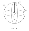
- the specimen (S) is positioned where an X tilt axis and a Y tilt axis of an Ewald sphere S(E) in a reciprocal space meet.
- the crystal axes of H1, H2, and H3 diffracted by the corresponding crystal plane of the specimen (S) can be checked from a screen of the transmission electron microscope.
- the crystal axis of H1 is a ( h 1 k 1 l 1 ) crystal axis (or crystal plane) diffracted by the corresponding crystal plane of the specimen (S)
- the crystal axis of H2 is a ( h 2 k 2 l 2 ) crystal axis
- the crystal axis of H3 is a ( h 3 k 3 l 3 ) crystal axis.
- an unknown crystal axis of H4 desired to be estimated can be found out using the algebraic relationship between the measured crystal axes of H1, H2, H3 and the tilt axes of Tx, Ty, Tz mounted on the transmission electron microscope.
- the measured crystal axes of H1, H2, and H3 are disposed on the coordinates formed by a Tx axis and a Ty axis, which are perpendicular to the X tilt axis and the Y tilt axes mounted on the transmission electron microscope, interplanar angles ( ⁇ 1 , ⁇ 2 , ⁇ 3 ) among the crystal axes of H1, H2, and H3 can be obtained, respectively.
- ⁇ 1 is an interplanar angle between the H1 ( h 1 k 1 l 1 ) and H2 ( h 2 k 2 l 2 )
- ⁇ 2 is an interplanar angle between the H2 ( h 2 k 2 l 2 ) and the H3 ( h 3 k 3 l 3 )
- ⁇ 3 is an interplanar angle between the H3 ( h 3 k 3 l 3 ) and H1 ( h 1 k 1 l 1 ).
- the crystal axis of H4 desired to be estimated can be obtained using the relationship between the measured interplanar angles of ⁇ 1 , ⁇ 2 , ⁇ 3 and the crystallographic interplanar angles of ⁇ 1 , ⁇ 2 , ⁇ 3 as shown in equations (3), and (4).
- the measured interplanar angles of ⁇ 1 , ⁇ 2, ⁇ 3 are obtained from the measured angle pairs of (Tx, Tz) on H1, H2, H3 and the angle pair of (Tx, Tz) on H4 desired to be estimated.
- the interplanar angle of ⁇ 1 can be obtained from the difference of (-10, 70) between the H1 and the H4 using equation (4).
- the crystallographically determined interplanar angles of ⁇ 1 , ⁇ 2 , ⁇ 3 are obtained from the known indices of ( h 1 k 1 l 1 ) ( h 2 k 2 l 2 ), ( h 3 k 3 l 3 ) on the corresponding crystal plane of H1, H2, H3 and an unknown indices of ( hkl ) on the corresponding crystal plane of H4 using equation (3).
- FIG. 3 is a flow chart illustrating the process of revealing the characteristics of the grain boundaries according to the present invention.
- (Tx, Ty) angle pairs of the respective crystal axes of H1, H2, and H3 are measured using the goniometer in order to measure the interplanar angles ( ⁇ 1 , ⁇ 2 , ⁇ 3 ) among the crystal axes H1, H2, and H3 (S10). And then, a measured angle pairs of (Tx, Ty) are chosen as a precise measured angle pairs which minimizing the difference between the measured interplanar angles and the crystallographically-calculated interplanar angles among the crystal axes of H1, H2, and H3 (S20).
- the three crystal axes of H1, H2, and H3 in a crystal desired to be observed are measured using the goniometer as shown in FIGs. 1 and 2 .
- the specimen ('S' in FIG. 1 ) is inclined to find out a crystal axis parallel to the direction of the transmitted E-beam in FIG. 1 , and the angle pairs of (Tx, Ty) indicated at the goniometer at that time are recorded. This process is performed for every grain desired to be observed.
- the respective angle pairs (Tx, Ty) of the crystal axes H(A)1( h 1 k 1 l 1 ), H(A)2( h 2 k 2 l 2 ), and H(A)3( h 3 k 3 l 3 ) of the grain 'A' and H(B)1( h 1 k 1 l 1 ), H(B)2( h 2 k 2 l 2 ), and H(B)3( h 3 k 3 / 3 ) of the grain 'B' are all measured.
- the interplanar angles among the crystal axes of H(A)1, H(A)2, and H(A)3 are calculated by equation (1) using the measured angle pairs of (Tx, Ty) on the crystal axes of H(A)1, H(A)2, and H(A)3.
- the interplanar angles among the crystal axes of H(A)1, H(A)2, H(A)3 are calculated by equation (2) using the miller indices of ( h 1 k 1 l 1 ), ( h 2 k 2 l 2 ), ( h 3 k 3 l 3 ) on the corresponding crystal axes of H(A)1, H(A)2, and H(A)3.
- the angle pairs of (Tx, Ty) are chosen as the precise angle pairs which make the difference between the measured interplanar angle and the crystallographically determined interplanar angle as small as possible. The reason is because if the difference between the measured interplanr angle based upon the three crystal axes and the crystallographically calculated angle is large, the orthogonality of the Cartesian coordinate system is degraded to result in much error in the estimated crystal axis H4.
- the tilt angle pairs of (Tx, Ty) on the related crystal axes are measured several times and a (Tx, Ty) angle at which the difference between the measured interplanar angles and the calculated interplanar angles is as small as possible is selected to thereby improve the orthogonality of the Cartesian coordinate system to its maximum level.
- FIG. 4 is a drawing illustrating a method for calculating the interplanar angles ( ⁇ 1 , ⁇ 2 , ⁇ 3 ) among the crystal axes of H(A)1, H(A)2, H(A)3 using the (Tx, Ty) angle pairs measured by the goniometer as a portion of FIG. 1 .
- FIG. 4 is a drawing illustrating a method for calculating the interplanar angles ( ⁇ 1 , ⁇ 2 , ⁇ 3 ) among the crystal axes of H(A)1, H(A)2, H(A)3 using the (Tx, Ty) angle pairs measured by the goniometer as a portion of FIG. 1 .
- FIG. 4 is a drawing illustrating a method for calculating the interplanar angles ( ⁇ 1 , ⁇ 2 , ⁇ 3 ) among the crystal axes of H(A)1, H(A)2, H(A)3 using the (Tx, Ty) angle pairs measured by the goniometer as a portion of FIG. 1 .
- Reference numeral 15 denotes a centered E-beam.
- the interplanar angles ( ⁇ 1 , ⁇ 2 , ⁇ 3 ) among the three crystal axes of H(A)1, H(A)2, and H(A)3 can be all obtained by equation (1) based upon the carefully measured (Tx, Ty) angle pairs using the goniometer.
- the interplanar angles of ( ⁇ 1 , ⁇ 2 , ⁇ 3 ) in grain B can be obtained by equation (1) using the measured angle pairs of (Tx 1 , Ty 1 ), (Tx 2 , Ty 2 ), (Tx 3 , Ty 3 ) on H(B)1, H(B)2, and H(B)3 with respect to the grain 'B', and the crystallographically calculated interpalnar angles among H(B)1, H(B)2, and H(B)3 can be obtained by equation (2).
- three crystal axes of H(B)1, H(B)2, and H(B)3 may be chosen which are as close as possible to the centered transmitted E-beam.
- a second method is to use both two crystal axes rotated by an angle ⁇ along Tx axis and Ty axis, respectively and one crystal axis parallel with Tz.
- the crystal axes rotated by an angle ⁇ can be calculated using equation (3) and equation (4).
- the value of ⁇ may be an arbitrary value which is larger than 0 but smaller than or the same as 10, and preferably, a value with good orthogonality of misorientation matrix may be selected from the corresponding range.
- a third method is that crystal axes vectors when rotated by a same arbitrary angle ⁇ along the X axis and along the Y axis are calculated using equation (3) and equation (4), and then three crystal axes vectors obtained by subtracting a crystal axis vector parallel to the Tz from the rotated crystal axes vectors are used.
- the value ⁇ may be an arbitrary value which is larger than 0 but smaller than or the same as 10, and preferably, a value with good orthogonality of orthogonal coordinates may be selected
- the fourth method is to use two vectors having parallel component to the direction of Tx[100], Ty[010], and one vector parallel to the Tz[001] in the subtracted vectors at the third method.
- the correspondence matrix is established for all the grains c i desired to be observed.
- 'i' indicates 'A' and 'B'.
- the first method when three crystal axes are precisely measured, the accurate values can be expressed mathematically.
- the crystal may be bent or rotated because the specimen is so thin, and the three crystal axes cannot be measured with respect to the same zone axis, so it is not possible to precisely measure the three crystal axes. This results in an inevitable error. Such error may be discriminated by an angle between the three crystal axis calculated by equation (1) and equation (2).
- the first method is the most accurate method in linear algebraic aspect, it is disadvantageous in that the orthogonality of the Cartesian coordinate system deteriorates because of the inevitable error in measuring the tilt angles with respect to the three crystal axes.
- the second method aims to improve the orthogonality of the misorientation matrix.
- the crystal axes rotated by the same arbitrary angle of ⁇ , along the X axis and along the Y axis as shown in FIG. 6 are used, and the crystal axes obtained by rotating by the angle ⁇ can be calculated using equation (3) and equation (4).
- the correspondence matrix is established for all the grains c i desired to be observed.
- the value ⁇ may be an arbitrary value which is larger than 0 but smaller than or the same as 10, and preferably, a value with good orthogonality of misorientation matrix may be selected from the corresponding range.
- the third method aims to improve the orthogonality of the crystal axes and the tilting axes.
- elements of matrix of the established equation (6) are used.
- the values obtained by rotating by the same arbitrary angle of ⁇ along the X axis and along the Y axis as shown in FIG. 7 are used, and the values obtained by rotation of the angle ⁇ can be calculated using equation (3) and equation (4).
- the value ⁇ may be an arbitrary value which is larger than 0 but smaller than or the same as 10, and preferably, a value with good orthogonality of orthogonal coordinates may be selected from the corresponding range.
- the third method features that the elements of the correspondence matrix are closely parallel to the direction of Tx[100], Ty[010], and Tz[001], so good orthogonality can be obtained between the crystal axes and the tilting axes.
- the fourth method features that the elements of the correspondence matrix is composed of the parallel component to the direction of Tx[100], Ty[010], and Tz[001] in the subtracted vectors at the third method.
- equation (6) is a matrix without orthogonality while equation (7) is a matrix with orthogonality.
- equation (6) itself cannot reduce a measurement error and the orthogonality of the misorientation matrix can be improved through the subsequent step.
- the misorientation matrix is established between the grains using the relationship between the crystal axes and the tilt axes established by equation (5), equation (6) or equation (7).
- the misorientation matrix can be configured for each grain boundary desired to be observed based on equation (11).
- misorientation matrix configured by equation (8). For example, whether or not the grain boundary is a CSL (Coincident Site Lattice) grain boundary or what kind of CSL grain boundary it is can be discriminated.
- misorientation matrix is configured from an axis-angle pair according to indices of the CSL, namely, ⁇ values ( ⁇ 3, ⁇ 5, ⁇ 7, ...), reported in the document.
- the product of the inverse matrices of the misorientation matrix measured in the present invention and the misorientation matrix configured from the CSL grain boundary data are calculated.
Landscapes
- Chemical & Material Sciences (AREA)
- Analytical Chemistry (AREA)
- Physics & Mathematics (AREA)
- Health & Medical Sciences (AREA)
- Life Sciences & Earth Sciences (AREA)
- Biochemistry (AREA)
- General Health & Medical Sciences (AREA)
- General Physics & Mathematics (AREA)
- Immunology (AREA)
- Pathology (AREA)
- Analysing Materials By The Use Of Radiation (AREA)
Applications Claiming Priority (1)
| Application Number | Priority Date | Filing Date | Title |
|---|---|---|---|
| KR1020080071414A KR100995877B1 (ko) | 2008-07-23 | 2008-07-23 | 투과전자현미경의 고니오미터를 이용한 이웃하는 결정립의결정학적 방위관계 측정장치 및 그에 의한 결정립계 특성규명 방법 |
Publications (2)
| Publication Number | Publication Date |
|---|---|
| EP2148190A2 true EP2148190A2 (de) | 2010-01-27 |
| EP2148190A3 EP2148190A3 (de) | 2011-02-23 |
Family
ID=41327298
Family Applications (1)
| Application Number | Title | Priority Date | Filing Date |
|---|---|---|---|
| EP08021545A Withdrawn EP2148190A3 (de) | 2008-07-23 | 2008-12-11 | Vorrichtung zur Messung der Ausrichtung des Verhältnisses zwischen benachbarten Körnern anhand eines Winkelmessers in einem Übertragungselektronenmikroskop und Verfahren zum Aufzeigen der Eigenschaften von Korngrenzen |
Country Status (4)
| Country | Link |
|---|---|
| US (1) | US8008621B2 (de) |
| EP (1) | EP2148190A3 (de) |
| JP (1) | JP5393126B2 (de) |
| KR (1) | KR100995877B1 (de) |
Cited By (3)
| Publication number | Priority date | Publication date | Assignee | Title |
|---|---|---|---|---|
| CN103234991A (zh) * | 2013-04-01 | 2013-08-07 | 合肥晶桥光电材料有限公司 | 一种晶体材料晶向的测量方法 |
| CN106802306A (zh) * | 2017-03-13 | 2017-06-06 | 燕山大学 | 在透射电子显微镜下快速精确测量小角晶界取向差的方法 |
| EP3633709A4 (de) * | 2017-05-31 | 2021-03-10 | Nippon Steel Corporation | Vorrichtung zur kalkulation des ausmasses eines neigungswinkels, probenständer, geladene teilchenstrahlvorrichtung und programm |
Families Citing this family (4)
| Publication number | Priority date | Publication date | Assignee | Title |
|---|---|---|---|---|
| US9103769B2 (en) * | 2009-12-15 | 2015-08-11 | The Regents Of The University Of California | Apparatus and methods for controlling electron microscope stages |
| JP2014240780A (ja) * | 2013-06-11 | 2014-12-25 | 株式会社東芝 | 試料構造分析方法、透過電子顕微鏡およびプログラム |
| US20180224859A1 (en) * | 2017-02-08 | 2018-08-09 | Ford Global Technologies, Llc | Tornado Detection Systems And Methods |
| EP3616230B1 (de) * | 2017-04-27 | 2023-08-02 | King Abdullah University Of Science And Technology | System und verfahren zur probenausrichtung bei einem transmissionselektronenmikroskop |
Family Cites Families (16)
| Publication number | Priority date | Publication date | Assignee | Title |
|---|---|---|---|---|
| US4247771A (en) * | 1979-10-09 | 1981-01-27 | Karl M. Kadish | Parafocusing diffractometer |
| GB8814343D0 (en) * | 1988-06-16 | 1988-07-20 | Gersan Ets | Determining misorientation in crystal |
| US5235523A (en) * | 1989-11-13 | 1993-08-10 | The United States Of America As Represented By The Secretary Of Commerce | Apparatus and methods for identifying and comparing lattice structures and determining lattice structure symmetries |
| US4961210A (en) * | 1990-02-28 | 1990-10-02 | The United States Of America As Represented By The Secretary Of The Navy | High resolution technique and instrument for measuring lattice parameters in single crystals |
| US5179280A (en) * | 1990-10-12 | 1993-01-12 | Chi & Associated Inc. | Computer control of the electron microscope sample stage |
| JPH05142168A (ja) | 1991-11-15 | 1993-06-08 | Nippon Steel Corp | 鋼板の結晶粒度の評価方法及び評価装置 |
| JP2777505B2 (ja) * | 1992-07-29 | 1998-07-16 | 株式会社日立製作所 | 自動分析電子顕微鏡および分析評価方法 |
| JPH06103948A (ja) | 1992-09-24 | 1994-04-15 | Nippon Steel Corp | 透過電子顕微鏡用試料傾斜操作方法 |
| US5481111A (en) * | 1994-01-03 | 1996-01-02 | Philips Electronics North America Corporation | Electron microscope having a goniometer controlled from the image frame of reference |
| JP3672728B2 (ja) | 1998-04-03 | 2005-07-20 | 日本電子株式会社 | 透過型電子顕微鏡における自動試料傾斜装置 |
| JP2000277044A (ja) | 1999-03-24 | 2000-10-06 | Hitachi Ltd | 走査電子顕微鏡 |
| JP2002279925A (ja) * | 2001-03-19 | 2002-09-27 | National Institute Of Advanced Industrial & Technology | 高分解能複合型顕微鏡 |
| DE10128630A1 (de) * | 2001-06-13 | 2003-01-02 | Freiberger Compound Mat Gmbh | Vorrichtung und Verfahren zur Bestimmung der Orientierung einer kristallografischen Ebene relativ zu einer Kristalloberfläche sowie Vorrichtung und Verfahren zum Trennen eines Einkristalls in einer Trennmaschine |
| GB0222334D0 (en) | 2001-10-04 | 2002-10-30 | X Ray Res Gmbh | Automatic adjusting method for a goniometer and associated device |
| KR100721905B1 (ko) | 2005-12-30 | 2007-05-28 | 포항공과대학교 산학협력단 | 방사광 스침각입사 산란장치 제어방법 |
| JP4653666B2 (ja) | 2006-01-23 | 2011-03-16 | 株式会社日立ハイテクノロジーズ | 電子顕微鏡およびその制御方法 |
-
2008
- 2008-07-23 KR KR1020080071414A patent/KR100995877B1/ko not_active Expired - Fee Related
- 2008-12-11 EP EP08021545A patent/EP2148190A3/de not_active Withdrawn
- 2008-12-15 JP JP2008318286A patent/JP5393126B2/ja not_active Expired - Fee Related
- 2008-12-24 US US12/343,853 patent/US8008621B2/en active Active
Non-Patent Citations (2)
| Title |
|---|
| LANGE ET AL: "Mathematical characterization of a general bicrystal", ACTA METALLURGICA, PERGAMON PRESS, US LNKD- DOI:10.1016/0001-6160(67)90207-6, vol. 15, no. 2, 1 February 1967 (1967-02-01), pages 311-318, XP024349153, ISSN: 0001-6160 [retrieved on 1967-02-01] * |
| QING L ET AL: "New method for determining grain boundary parameters", ULTRAMICROSCOPY, ELSEVIER, AMSTERDAM, NL LNKD- DOI:10.1016/0304-3991(92)90211-2, vol. 41, no. 4, 1 June 1992 (1992-06-01), pages 317-321, XP025759064, ISSN: 0304-3991 [retrieved on 1992-06-01] * |
Cited By (5)
| Publication number | Priority date | Publication date | Assignee | Title |
|---|---|---|---|---|
| CN103234991A (zh) * | 2013-04-01 | 2013-08-07 | 合肥晶桥光电材料有限公司 | 一种晶体材料晶向的测量方法 |
| CN103234991B (zh) * | 2013-04-01 | 2015-11-25 | 合肥晶桥光电材料有限公司 | 一种晶体材料晶向的测量方法 |
| CN106802306A (zh) * | 2017-03-13 | 2017-06-06 | 燕山大学 | 在透射电子显微镜下快速精确测量小角晶界取向差的方法 |
| CN106802306B (zh) * | 2017-03-13 | 2019-02-22 | 燕山大学 | 在透射电子显微镜下快速精确测量小角晶界取向差的方法 |
| EP3633709A4 (de) * | 2017-05-31 | 2021-03-10 | Nippon Steel Corporation | Vorrichtung zur kalkulation des ausmasses eines neigungswinkels, probenständer, geladene teilchenstrahlvorrichtung und programm |
Also Published As
| Publication number | Publication date |
|---|---|
| EP2148190A3 (de) | 2011-02-23 |
| KR100995877B1 (ko) | 2010-11-22 |
| US8008621B2 (en) | 2011-08-30 |
| US20100019145A1 (en) | 2010-01-28 |
| JP5393126B2 (ja) | 2014-01-22 |
| KR20100010527A (ko) | 2010-02-02 |
| JP2010027592A (ja) | 2010-02-04 |
Similar Documents
| Publication | Publication Date | Title |
|---|---|---|
| EP2148190A2 (de) | Vorrichtung zur Messung der Ausrichtung des Verhältnisses zwischen benachbarten Körnern anhand eines Winkelmessers in einem Übertragungselektronenmikroskop und Verfahren zum Aufzeigen der Eigenschaften von Korngrenzen | |
| US12066385B2 (en) | Raman spectroscopy based measurements in patterned structures | |
| Vlieg et al. | Relaxations in the missing-row structure of the (1× 2) reconstructed surfaces of Au (110) and Pt (110) | |
| Cline et al. | The optics and alignment of the divergent beam laboratory X-ray powder diffractometer and its calibration using NIST standard reference materials | |
| US6301330B1 (en) | Apparatus and method for texture analysis on semiconductor wafers | |
| Murray et al. | Applied and residual stress determination using X‐ray diffraction | |
| EP3835767B1 (de) | Steuerungsvorrichtung, system, verfahren und programm | |
| US6873681B2 (en) | Method of estimating preferred orientation of polycrystalline material | |
| EP1540319B1 (de) | Quantitative phasenanalyse strukturierter polykristalliner materialien | |
| JP5998666B2 (ja) | X線分析装置及びx線分析方法 | |
| Strocov et al. | Three-dimensional band mapping by angle-dependent very-low-energy electron diffraction and photoemission: methodology and application to Cu | |
| Wang et al. | Line-rotated remapping for high-resolution electron backscatter diffraction | |
| TWI912541B (zh) | 用於正則化應用特定半導體測量系統參數設定之最佳化之方法及系統 | |
| Bauch et al. | Innovative Analysis of X‐ray Microdiffraction Images on Selected Applications of the Kossel Technique | |
| CN105548227B (zh) | 一种InAlSb薄膜中铝组分含量的测定方法及装置 | |
| CN115727952B (zh) | 一种偏振度测量仪的全局校准与测量方法及装置 | |
| Han et al. | Blind lattice-parameter determination of cubic and tetragonal phases with high accuracy using a single EBSD pattern | |
| He | Two-dimensional powder diffraction | |
| JPS649575B2 (de) | ||
| He | Stress measurement | |
| Jeong et al. | Characterization of the parameters relating adjacent grains using transmission electron microscopy | |
| KR101034770B1 (ko) | 투과전자현미경의 고니오미터를 이용한 결정립계의법선벡터 측정장치 및 그에 의한 결정립계 법선벡터측정방법 | |
| CN112285028A (zh) | 偏振检测标定方法、偏振检测方法及偏振检测装置 | |
| Bull et al. | An improved method for calibrating time-of-flight Laue single-crystal neutron diffractometers | |
| CN121784324A (zh) | 一种晶体界面旋转角和倾斜角的量测及解耦合方法 |
Legal Events
| Date | Code | Title | Description |
|---|---|---|---|
| PUAI | Public reference made under article 153(3) epc to a published international application that has entered the european phase |
Free format text: ORIGINAL CODE: 0009012 |
|
| AK | Designated contracting states |
Kind code of ref document: A2 Designated state(s): AT BE BG CH CY CZ DE DK EE ES FI FR GB GR HR HU IE IS IT LI LT LU LV MC MT NL NO PL PT RO SE SI SK TR |
|
| AX | Request for extension of the european patent |
Extension state: AL BA MK RS |
|
| PUAL | Search report despatched |
Free format text: ORIGINAL CODE: 0009013 |
|
| AK | Designated contracting states |
Kind code of ref document: A3 Designated state(s): AT BE BG CH CY CZ DE DK EE ES FI FR GB GR HR HU IE IS IT LI LT LU LV MC MT NL NO PL PT RO SE SI SK TR |
|
| AX | Request for extension of the european patent |
Extension state: AL BA MK RS |
|
| 17P | Request for examination filed |
Effective date: 20110818 |
|
| AKX | Designation fees paid |
Designated state(s): AT BE BG CH CY CZ DE DK EE ES FI FR GB GR HR HU IE IS IT LI LT LU LV MC MT NL NO PL PT RO SE SI SK TR |
|
| 17Q | First examination report despatched |
Effective date: 20140917 |
|
| STAA | Information on the status of an ep patent application or granted ep patent |
Free format text: STATUS: THE APPLICATION IS DEEMED TO BE WITHDRAWN |
|
| 18D | Application deemed to be withdrawn |
Effective date: 20161028 |