EP2148149A2 - Hydraulikventilanordnung für wandmontierte Boiler - Google Patents
Hydraulikventilanordnung für wandmontierte Boiler Download PDFInfo
- Publication number
- EP2148149A2 EP2148149A2 EP09166063A EP09166063A EP2148149A2 EP 2148149 A2 EP2148149 A2 EP 2148149A2 EP 09166063 A EP09166063 A EP 09166063A EP 09166063 A EP09166063 A EP 09166063A EP 2148149 A2 EP2148149 A2 EP 2148149A2
- Authority
- EP
- European Patent Office
- Prior art keywords
- assembly
- sub
- hydraulic valve
- pipe
- valve assembly
- Prior art date
- Legal status (The legal status is an assumption and is not a legal conclusion. Google has not performed a legal analysis and makes no representation as to the accuracy of the status listed.)
- Granted
Links
Images


Classifications
-
- F—MECHANICAL ENGINEERING; LIGHTING; HEATING; WEAPONS; BLASTING
- F24—HEATING; RANGES; VENTILATING
- F24H—FLUID HEATERS, e.g. WATER OR AIR HEATERS, HAVING HEAT-GENERATING MEANS, e.g. HEAT PUMPS, IN GENERAL
- F24H9/00—Details
- F24H9/14—Arrangements for connecting different sections, e.g. in water heaters
- F24H9/142—Connecting hydraulic components
Definitions
- the present invention relates to a multifunction hydraulic assembly for combined wall-mounted boilers.
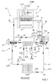
- Figure 1 designated as a whole by 10 is a combined autonomous system for heating premises and producing hot water.
- the system 10 is of a known type and consequently belongs to the prior art.
- the system 10 comprises a wall-mounted boiler 11, a hydraulic network 12, which connects the wall-mounted boiler 11 hydraulically with the water-using devices, and a hydraulic valve assembly 13, which has the purpose of adjusting the flowrates of water from/to the wall-mounted boiler 11.
- the system 10 is completed by at least one tap (RB) for delivery of sanitary hot water and by at least one heating element (ER) for heating premises both connected up to the hydraulic network 12.
- RB tap
- ER heating element
- the gas-fired wall-mounted boiler 11 comprises a casing 14 (normally made of sheet metal), housed inside which are a atmospheric gas burner 15, a main heat exchanger 16, and a flue (CHM) for evacuation of the fumes produced by combustion of the gas.
- the flue (CHM) is provided with a fan (VT).
- the hydraulic valve assembly 13 comprises, in turn, an inlet pipe 17 for the sanitary cold water (FS) coming from a water mains supply (not shown).
- FS sanitary cold water
- the inlet pipe 17 envisages a flowmeter 18 for intake of the sanitary cold water (FS), which is set in a coupling 19 for connection with a secondary heat exchanger 20; in addition, the heat exchanger 20 is advantageously, though not necessarily, of the plate type.
- FS sanitary cold water
- Departing from the heat exchanger 20 is a pipe 21 for outlet for the sanitary hot water (CS) sent to the tap (RB).
- the coupling 19 is provided with a deviation pipe 22, which envisages, in turn, a tap 23 for filling a primary circuit (C1), which, as will be seen, has the purpose of supplying the aforesaid heating element (ER) with hot water.
- a deviation pipe 22 envisages, in turn, a tap 23 for filling a primary circuit (C1), which, as will be seen, has the purpose of supplying the aforesaid heating element (ER) with hot water.
- the hydraulic valve assembly 13 further comprises a three-way valve 24 driven by a motor 25 and a pump 26 for recirculation into the main circuit (C1).
- the three-way valve 24 is used for activating a secondary circuit (C2) (for the sanitary water), which comprises the secondary heat exchanger 20.
- Said secondary circuit (C2) is activated in the presence of a request for sanitary hot water by a user.
- a pressure switch 27A of the primary circuit (C1) Installed alongside the pump 26 is a pressure switch 27A of the primary circuit (C1); the pressure switch 27A guarantees the minimum operating pressure of the wall-mounted boiler 11.
- a safety valve 27B of the primary circuit (C1) Located in the vicinity of the pump 26 an also a safety valve 27B of the primary circuit (C1), a degassing air valve (DG) of the central body of the pump 26, and a pipe tap for a manometer (MN).
- DG degassing air valve
- MN manometer
- the hydraulic valve assembly 13 illustrated in Figure 1 is not compact, and the elements that make it up are arranged in a non-rational way and in such a way that installation by specialized operators is not intuitive and immediate.
- the hydraulic valve assembly 13 shown in Figure 1 envisages the use of a plurality of connection elements between the various components, all this at the expense of compactness, reliability and cost of the hydraulic valve assembly 13 itself.
- the main aim of the present invention is to provide a hydraulic valve assembly for wall-mounted boilers that is extremely compact and the constitutive elements of which are arranged in a rational way.
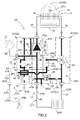
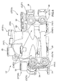
- FIG. 2 Shown in Figure 2 is a system 10* provided with a newly devised hydraulic valve assembly 13*.
- the hydraulic valve assembly 13* further comprises a shut-off tap (IR) set in the by-pass pipe 34.
- IR shut-off tap
- the pump 26 has been set centrally with respect to the secondary heat exchanger 20.
- the three-way valve 24 and the corresponding motor 25 are located on a first side (PP) (in this case on the right of the pump 26) with respect to the secondary heat exchanger 20 and to the pump 26.
- PP first side
- a second side (opposite to the first side (PP) with respect to the secondary heat exchanger 20 and to the pump 26) are the inlet pipe 17 for the sanitary cold water (FS) and the pipe 21 for outlet for the sanitary hot water (CS) to the tap (RB).
- the inlets and the outlets of the heating water (FR), (CR) and of the sanitary water (FS), (CS), are divided, respectively, into two distinct groups that do not cross over one another, and are not intertwined.
- the sanitary hot water (CS) In order for the sanitary hot water (CS) to be on the left with respect to the sanitary cold water (FS), the sanitary water coming from a point (P1) (where the coupling 19 ends) flows into the heat exchanger 20 towards a point (P2), starting from which is the pipe 21 for supply of the tap (RB). In particular, the sanitary water flows towards a point (P3) that is located on the same side as the point (P1).
- a second vertical portion 21B of the pipe 21 comes to be located to the left of the inlet pipe 17 for the sanitary cold water (FS), thus respecting the conventions adopted in the sector of hydraulic systems, which require the pipe for the sanitary hot water (possibly equipped with a tap) to be to the left of the pipe for delivery of the sanitary cold water.
- FS sanitary cold water
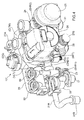
- hydraulic valve assembly 13* envisages:
- the three sub-assemblies (STG1), (STG2), (STG3) comprise fast-coupling hydraulic means for connection to one another and to the rest of the hydraulic network.
- the sub-assemblies (STG2), (STG3) envisage fast-coupling mechanical means for connection to the secondary heat exchanger 20 (see hereinafter).
- the three sub-assemblies (STG1), (STG2), (STG3) are made of composite material, they can each be formed in a single enbloc assembly, i.e., with a single moulding operation.
- all three sub-assemblies (STG1), (STG2), (STG3) can be produced together in a single enbloc assembly, i.e., with a single moulding operation.
- the secondary heat exchanger 20 represents a plate for assemblage of the three sub-assemblies (STG1), (STG2), (STG3).
- the three sub-assemblies (STG1), (STG2), (STG3) are fixed to the secondary heat exchanger 20 by means of just two screws (SHR1) and (SHR2).
- Each screw (SHR1), (SHR2) is first inserted into a corresponding hole (HL1), (HL2) made, respectively, in the second, lateral, sub-assembly (STH2) and in the third, lateral, sub-assembly (STG3) ( Figure 6 ).
- each screw (SHR1), (SHR2) is screwed in a respective threaded seat (SD1), (SD2), which is located on the secondary heat exchanger 20 ( Figure 5 ).
- the two lateral hydraulic sub-assemblies (STG2) and (STG3) each envisage a respective pair of headers (CLT1), (CLT2), (CLT3), (CLT4), which are designed to be connected to similar headers (not shown in Figure 6 ) present on the secondary heat exchanger 20.
- the aforesaid device 40 for crossing of the sanitary waters at inlet to and outlet from the secondary heat exchanger 20.
- the crossing device 40 from the thermal standpoint, is "zero balance" in the sense that the amount of heat yielded by the sanitary hot water is substantially equal to the amount of heat received by the same sanitary cold water at inlet. In addition, in the device 40 there is no mixing between the sanitary cold water and the sanitary hot water.
- One of the advantages of the hydraulic valve assembly 13* forming the subject of the present invention consists in having defined a new arrangement of the system connections on the bottom closing plate of the casing 14 of the boiler 11 in order to compact further the overall dimensions of the hydraulic valve assembly 13* and consequently reduce the total number of components, with a consequent marked reduction in production costs.
- interventions have been made, delimiting a space surrounding the secondary plate heat exchanger and positioning all the components for operation and control in a compact way.
- the compacting has led to a superposition with crossing of the connections for the sanitary-water circuit of the plate heat exchanger between the inlet for the sanitary cold water and the outlet for the sanitary hot water.
- composite material is meant a thermoplastic material, also referred to as “technopolymer”, which guarantees a good resistance to high operating temperatures, allied to a low permeability of water absorption (hydrolysis).
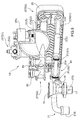
- the volute (VLT) of the pump 26, with corresponding intake header (CLTA) and delivery header (CLTM), a supplementary attachment (ATT) of the three-way valve 24 (useful in the case where it is desired to displace the three-way valve), a tap (PRS) for the manometer (MN) (not shown in Figure 7 ) are integrated in the first, central, sub-assembly (STG1).
- STG1 the two lateral sub-assemblies
- STG3 grip between them the first sub-assembly (STG1) comprising the volute (VLT) of the pump 26 and the corresponding elements seen previously connected thereto.
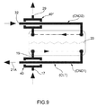
- the hydraulic assembly 13* also envisages a device 40 for crossing of the sanitary waters at inlet to and outlet from the heat exchanger 20.
- first horizontal portion 21A of the pipe 21 for outlet of the sanitary hot water Housed in the first pipe (CND1) is a first horizontal portion 21A of the pipe 21 for outlet of the sanitary hot water.
- the first pipe (CND1) and the horizontal portion 21A are coaxial.
- the horizontal portion 21A has a diameter smaller than that of the first pipe (CND1).
- Obtained by plastic deformation on the first portion 21A are two flanges (FLG1) and (FLG2) shaped like an annulus, equipped with respective O-rings.
- the sanitary hot water (CS) flows in the horizontal portion 21A and heats the sanitary cold water (FS) that enters the inlet pipe 17 and flows around the horizontal portion 21A itself before entering the secondary heat exchanger 20.
- Crossing between the coupling 19 and the pipe (CND1) defines the crossing device 40.
- the second, top, pipe (CND2) traverses, in use, the volute (VLT) of the pump 26 and has the purpose of rendering the volute (VLT) itself fixed with respect to the body of the secondary heat exchanger 20.
- the second, top, pipe (CND2) can be broken down into a number of pieces that can be connected to one another, at least one of which is inserted in the volute (VLT) itself.
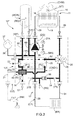
- the hydraulic assembly 13* is also provided with a delivery pipe 50 for delivery to a micro-accumulation tank (MCR) ( Figure 3 ) and a return pipe 60 for return of the hot water contained in the micro-accumulation tank (MCR) to the primary circuit (C1).
- MCR micro-accumulation tank
- C1 primary circuit
- Said two interruptions (INT1), (INT2) are provided at the moment of production of the second sub-assembly (STG2).
- a plug is provided in the pipe 36, which disconnects the cold water entering the micro-accumulation tank (MCR) from the hot water that flows out.
- the micro-accumulation tank is a 4-litre or 5-litre tank, kept pre-heated by an electrical resistor (RE) ( Figure 3 ), which enables the instantaneous boiler 11 to reduce drastically the time for waiting for the production of hot water at 50°C when said boiler 11 starts cold. It basically functions as thermal flywheel in the initial step of intake of the sanitary hot water.
- the pump 26 goes into operation and recalls hot water at 70-80°C (from the pipe 60) present in the micro-accumulation tank (MCR), said hot water being sent to the primary heat exchanger 16 through the pipe 29 so as to bring the hot water of the primary circuit (C1) rapidly into steady-state conditions and, evidently indirectly, heat also up the sanitary water fast by means of the secondary heat exchanger 20.
- the delivery pipe 50 and the return pipe 60 of the micro-accumulation tank (MCR) are provided, respectively, with an attachment (IAF) for the cold water and an attachment (UAC) for hot water for immediate needs.
- a peculiarity of the present invention lies in that the two attachments (IAF) and (UAC) are integrated in the second sub-assembly (STG2), hence enabling elimination of inconvenient coupling pipes used in known existing embodiments.
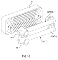
- Each device 40 and 40* for crossing of the water entering/leaving the secondary heat exchanger 20 enables the connections of the heat exchanger to be rendered reversible, using at will, on the right or on the left, the coupling headers.
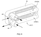
- FIGS 9 , 10 , and 11 show a particular arrangement, which envisages the use of a header (CLT), integrated in which are two water-crossing devices 40, 40*.
- CLT header
- the two water-crossing devices 40, 40* are both on the same side, even though it is possible to provide headers (not shown), in which the two crossing devices 40, 40* are set at the vertices of a diagonal of the heat exchanger 20.
- the main advantage of the hydraulic valve assembly forming the subject of the present invention consists in providing rational arrangements of the functional elements, with a significant reduction of the overall dimensions and a consequent significant cut in production costs.
Landscapes
- Engineering & Computer Science (AREA)
- Physics & Mathematics (AREA)
- Thermal Sciences (AREA)
- Chemical & Material Sciences (AREA)
- Combustion & Propulsion (AREA)
- Mechanical Engineering (AREA)
- General Engineering & Computer Science (AREA)
- Heat-Exchange Devices With Radiators And Conduit Assemblies (AREA)
Applications Claiming Priority (1)
| Application Number | Priority Date | Filing Date | Title |
|---|---|---|---|
| IT000456A ITBO20080456A1 (it) | 2008-07-21 | 2008-07-21 | Gruppo idraulico valvolare per caldaie murali |
Publications (4)
| Publication Number | Publication Date |
|---|---|
| EP2148149A2 true EP2148149A2 (de) | 2010-01-27 |
| EP2148149A8 EP2148149A8 (de) | 2010-05-19 |
| EP2148149A3 EP2148149A3 (de) | 2016-08-17 |
| EP2148149B1 EP2148149B1 (de) | 2018-10-24 |
Family
ID=40589622
Family Applications (1)
| Application Number | Title | Priority Date | Filing Date |
|---|---|---|---|
| EP09166063.9A Active EP2148149B1 (de) | 2008-07-21 | 2009-07-21 | Hydraulikventilanordnung für wandmontierte Boiler |
Country Status (4)
| Country | Link |
|---|---|
| EP (1) | EP2148149B1 (de) |
| DK (1) | DK2148149T3 (de) |
| ES (1) | ES2703009T3 (de) |
| IT (1) | ITBO20080456A1 (de) |
Cited By (7)
| Publication number | Priority date | Publication date | Assignee | Title |
|---|---|---|---|---|
| EP2397777A1 (de) * | 2010-06-19 | 2011-12-21 | Grundfos Management A/S | Gehäuseeinheit für eine Heizungsanlage |
| EP2629019A1 (de) * | 2012-02-17 | 2013-08-21 | Grundfos Holding A/S | Gehäuseeinheit für ein Heizgerät |
| WO2015091778A1 (en) * | 2013-12-20 | 2015-06-25 | Ec Power A/S | Heat exchanger apparatus |
| ITUB20160469A1 (it) * | 2016-01-22 | 2017-07-22 | Ivar Spa | Dispositivo di regolazione per impianti termici |
| EP3222929A4 (de) * | 2014-11-19 | 2018-08-08 | Kyungdong Navien Co., Ltd. | Kessel mit in der wasserohrleitung integriertem rückschlagventil |
| EP3361182A1 (de) * | 2017-02-08 | 2018-08-15 | Grundfos Holding A/S | Hydraulische baueinheit für eine heizungs- oder klimaanlage |
| IT201800000748A1 (it) * | 2018-01-11 | 2019-07-11 | Elbi Int Spa | Gruppo idraulico per apparecchiatura riscaldante. |
Families Citing this family (1)
| Publication number | Priority date | Publication date | Assignee | Title |
|---|---|---|---|---|
| SK9983Y1 (sk) * | 2023-05-02 | 2024-02-28 | Protherm Production S.R.O. | Hydraulický modul s voliteľnými doskami a vykurovacie zariadenie vybavené hydraulickým modulom |
Family Cites Families (5)
| Publication number | Priority date | Publication date | Assignee | Title |
|---|---|---|---|---|
| GB2365953B (en) * | 2000-07-07 | 2004-08-25 | George Curtis | Heating systems |
| FR2813950B1 (fr) * | 2000-09-14 | 2002-11-15 | Chaffoteaux Et Maury | Vanne distributrice hydraulique pour systeme de production d'eau chaude de chauffage et d'eau chaude sanitaire |
| EP1418387B1 (de) * | 2002-11-08 | 2016-01-13 | Grundfos A/S | Kompaktheizungsanlage mit zwei Heizkreisen |
| ATE504787T1 (de) * | 2003-11-03 | 2011-04-15 | Grundfos As | Baueinheit für eine kompaktheizungsanlage |
| DE502005009452D1 (de) * | 2005-03-15 | 2010-06-02 | Grundfos Management As | Baueinheit für eine Kompaktheizungsanlage |
-
2008
- 2008-07-21 IT IT000456A patent/ITBO20080456A1/it unknown
-
2009
- 2009-07-21 DK DK09166063.9T patent/DK2148149T3/en active
- 2009-07-21 ES ES09166063T patent/ES2703009T3/es active Active
- 2009-07-21 EP EP09166063.9A patent/EP2148149B1/de active Active
Cited By (13)
| Publication number | Priority date | Publication date | Assignee | Title |
|---|---|---|---|---|
| US9612036B2 (en) | 2010-06-19 | 2017-04-04 | Grundfos Management A/S | Housing unit for a heating system |
| EP2397777A1 (de) * | 2010-06-19 | 2011-12-21 | Grundfos Management A/S | Gehäuseeinheit für eine Heizungsanlage |
| EP2629019A1 (de) * | 2012-02-17 | 2013-08-21 | Grundfos Holding A/S | Gehäuseeinheit für ein Heizgerät |
| WO2013120649A1 (de) * | 2012-02-17 | 2013-08-22 | Grundfos Holding A/S | Gehäuseeinheit für ein heizgerät |
| CN104114952B (zh) * | 2012-02-17 | 2017-03-15 | 格兰富控股联合股份公司 | 用于加热器的壳体单元 |
| WO2015091778A1 (en) * | 2013-12-20 | 2015-06-25 | Ec Power A/S | Heat exchanger apparatus |
| EP3222929A4 (de) * | 2014-11-19 | 2018-08-08 | Kyungdong Navien Co., Ltd. | Kessel mit in der wasserohrleitung integriertem rückschlagventil |
| ITUB20160469A1 (it) * | 2016-01-22 | 2017-07-22 | Ivar Spa | Dispositivo di regolazione per impianti termici |
| EP3361182A1 (de) * | 2017-02-08 | 2018-08-15 | Grundfos Holding A/S | Hydraulische baueinheit für eine heizungs- oder klimaanlage |
| WO2018145975A3 (de) * | 2017-02-08 | 2018-10-18 | Grundfos Holding A/S | Hydraulische baueinheit für eine heizungs- oder klimaanlage |
| US11555617B2 (en) | 2017-02-08 | 2023-01-17 | Grundfos Holding A/S | Hydraulic unit for a heating or air-conditioning system |
| IT201800000748A1 (it) * | 2018-01-11 | 2019-07-11 | Elbi Int Spa | Gruppo idraulico per apparecchiatura riscaldante. |
| WO2019138347A1 (en) * | 2018-01-11 | 2019-07-18 | Elbi International S.P.A. | Hydraulic connection body |
Also Published As
| Publication number | Publication date |
|---|---|
| ES2703009T3 (es) | 2019-03-06 |
| ITBO20080456A1 (it) | 2010-01-22 |
| DK2148149T3 (en) | 2019-02-11 |
| EP2148149A3 (de) | 2016-08-17 |
| EP2148149B1 (de) | 2018-10-24 |
| EP2148149A8 (de) | 2010-05-19 |
Similar Documents
| Publication | Publication Date | Title |
|---|---|---|
| EP2148149B1 (de) | Hydraulikventilanordnung für wandmontierte Boiler | |
| CN102905590A (zh) | 用于加热水和产生蒸汽的装置 | |
| EP2942583B1 (de) | Blockartiger grundkoerper für eine hydraulikbaugruppe zur verwendung in einem wandmontierten boiler | |
| JP4743008B2 (ja) | ヒートポンプ式給湯装置 | |
| WO2021027234A1 (zh) | 水路控制系统和相变热水器 | |
| EP1831609B1 (de) | Wärmetauscher für einen kombikessel und kombikessel mit diesem wärmetauscher | |
| CN203771666U (zh) | 热水器 | |
| US12055348B2 (en) | Heat exchange apparatus and method of manufacturing the same | |
| CN204153956U (zh) | 热水器装置 | |
| EP3680574B1 (de) | Hydraulikbaugruppe | |
| EP1944554A2 (de) | Einheit und Verfahren zur Verteilung von Flüssigkeiten | |
| SK106394A3 (en) | Electrical instantaneous water heater | |
| CN111365494A (zh) | 一种自动开关阀芯 | |
| EP2362154B1 (de) | Hohler, monolitischer Verteiler für Heizsysteme | |
| CN205849266U (zh) | 一种即热式持续开水机 | |
| CN211316578U (zh) | 相变热水器的水路控制系统和相变热水器 | |
| CN218978626U (zh) | 一种带凉白开功能的壁挂式饮水机 | |
| KR100690278B1 (ko) | 이중관 구조를 갖는 온수 및 난방 겸용 보일러 | |
| CN220911793U (zh) | 一种台式冷热两用电开水器 | |
| EP3879926B1 (de) | Heizpatrone für eine ausgabevorrichtung und ausgabevorrichtung mit besagter heizpatrone | |
| GB2266762A (en) | Heating domestic water | |
| CN105661985A (zh) | 热水器双模式循环水暖椅 | |
| CN201005505Y (zh) | 具有防窜温功能的快速加热饮水机 | |
| CN208296311U (zh) | 热水器的热水水箱及具有其的空气源热泵热水器 | |
| JPH0328258Y2 (de) |
Legal Events
| Date | Code | Title | Description |
|---|---|---|---|
| PUAI | Public reference made under article 153(3) epc to a published international application that has entered the european phase |
Free format text: ORIGINAL CODE: 0009012 |
|
| AK | Designated contracting states |
Kind code of ref document: A2 Designated state(s): AT BE BG CH CY CZ DE DK EE ES FI FR GB GR HR HU IE IS IT LI LT LU LV MC MK MT NL NO PL PT RO SE SI SK SM TR |
|
| PUAL | Search report despatched |
Free format text: ORIGINAL CODE: 0009013 |
|
| AK | Designated contracting states |
Kind code of ref document: A3 Designated state(s): AT BE BG CH CY CZ DE DK EE ES FI FR GB GR HR HU IE IS IT LI LT LU LV MC MK MT NL NO PL PT RO SE SI SK SM TR |
|
| AX | Request for extension of the european patent |
Extension state: AL BA RS |
|
| RIC1 | Information provided on ipc code assigned before grant |
Ipc: F24H 9/14 20060101AFI20160708BHEP |
|
| STAA | Information on the status of an ep patent application or granted ep patent |
Free format text: STATUS: REQUEST FOR EXAMINATION WAS MADE |
|
| 17P | Request for examination filed |
Effective date: 20170217 |
|
| RBV | Designated contracting states (corrected) |
Designated state(s): AT BE BG CH CY CZ DE DK EE ES FI FR GB GR HR HU IE IS IT LI LT LU LV MC MK MT NL NO PL PT RO SE SI SK SM TR |
|
| GRAP | Despatch of communication of intention to grant a patent |
Free format text: ORIGINAL CODE: EPIDOSNIGR1 |
|
| STAA | Information on the status of an ep patent application or granted ep patent |
Free format text: STATUS: GRANT OF PATENT IS INTENDED |
|
| INTG | Intention to grant announced |
Effective date: 20180516 |
|
| GRAS | Grant fee paid |
Free format text: ORIGINAL CODE: EPIDOSNIGR3 |
|
| GRAA | (expected) grant |
Free format text: ORIGINAL CODE: 0009210 |
|
| STAA | Information on the status of an ep patent application or granted ep patent |
Free format text: STATUS: THE PATENT HAS BEEN GRANTED |
|
| AK | Designated contracting states |
Kind code of ref document: B1 Designated state(s): AT BE BG CH CY CZ DE DK EE ES FI FR GB GR HR HU IE IS IT LI LT LU LV MC MK MT NL NO PL PT RO SE SI SK SM TR |
|
| REG | Reference to a national code |
Ref country code: GB Ref legal event code: FG4D |
|
| REG | Reference to a national code |
Ref country code: CH Ref legal event code: EP |
|
| REG | Reference to a national code |
Ref country code: IE Ref legal event code: FG4D |
|
| REG | Reference to a national code |
Ref country code: AT Ref legal event code: REF Ref document number: 1057149 Country of ref document: AT Kind code of ref document: T Effective date: 20181115 |
|
| REG | Reference to a national code |
Ref country code: DE Ref legal event code: R096 Ref document number: 602009055216 Country of ref document: DE |
|
| REG | Reference to a national code |
Ref country code: DK Ref legal event code: T3 Effective date: 20190206 |
|
| REG | Reference to a national code |
Ref country code: NL Ref legal event code: MP Effective date: 20181024 |
|
| REG | Reference to a national code |
Ref country code: ES Ref legal event code: FG2A Ref document number: 2703009 Country of ref document: ES Kind code of ref document: T3 Effective date: 20190306 |
|
| REG | Reference to a national code |
Ref country code: LT Ref legal event code: MG4D |
|
| REG | Reference to a national code |
Ref country code: AT Ref legal event code: MK05 Ref document number: 1057149 Country of ref document: AT Kind code of ref document: T Effective date: 20181024 |
|
| PG25 | Lapsed in a contracting state [announced via postgrant information from national office to epo] |
Ref country code: NL Free format text: LAPSE BECAUSE OF FAILURE TO SUBMIT A TRANSLATION OF THE DESCRIPTION OR TO PAY THE FEE WITHIN THE PRESCRIBED TIME-LIMIT Effective date: 20181024 |
|
| PG25 | Lapsed in a contracting state [announced via postgrant information from national office to epo] |
Ref country code: PL Free format text: LAPSE BECAUSE OF FAILURE TO SUBMIT A TRANSLATION OF THE DESCRIPTION OR TO PAY THE FEE WITHIN THE PRESCRIBED TIME-LIMIT Effective date: 20181024 Ref country code: HR Free format text: LAPSE BECAUSE OF FAILURE TO SUBMIT A TRANSLATION OF THE DESCRIPTION OR TO PAY THE FEE WITHIN THE PRESCRIBED TIME-LIMIT Effective date: 20181024 Ref country code: AT Free format text: LAPSE BECAUSE OF FAILURE TO SUBMIT A TRANSLATION OF THE DESCRIPTION OR TO PAY THE FEE WITHIN THE PRESCRIBED TIME-LIMIT Effective date: 20181024 Ref country code: NO Free format text: LAPSE BECAUSE OF FAILURE TO SUBMIT A TRANSLATION OF THE DESCRIPTION OR TO PAY THE FEE WITHIN THE PRESCRIBED TIME-LIMIT Effective date: 20190124 Ref country code: LV Free format text: LAPSE BECAUSE OF FAILURE TO SUBMIT A TRANSLATION OF THE DESCRIPTION OR TO PAY THE FEE WITHIN THE PRESCRIBED TIME-LIMIT Effective date: 20181024 Ref country code: IS Free format text: LAPSE BECAUSE OF FAILURE TO SUBMIT A TRANSLATION OF THE DESCRIPTION OR TO PAY THE FEE WITHIN THE PRESCRIBED TIME-LIMIT Effective date: 20190224 Ref country code: LT Free format text: LAPSE BECAUSE OF FAILURE TO SUBMIT A TRANSLATION OF THE DESCRIPTION OR TO PAY THE FEE WITHIN THE PRESCRIBED TIME-LIMIT Effective date: 20181024 Ref country code: BG Free format text: LAPSE BECAUSE OF FAILURE TO SUBMIT A TRANSLATION OF THE DESCRIPTION OR TO PAY THE FEE WITHIN THE PRESCRIBED TIME-LIMIT Effective date: 20190124 Ref country code: FI Free format text: LAPSE BECAUSE OF FAILURE TO SUBMIT A TRANSLATION OF THE DESCRIPTION OR TO PAY THE FEE WITHIN THE PRESCRIBED TIME-LIMIT Effective date: 20181024 |
|
| PG25 | Lapsed in a contracting state [announced via postgrant information from national office to epo] |
Ref country code: GR Free format text: LAPSE BECAUSE OF FAILURE TO SUBMIT A TRANSLATION OF THE DESCRIPTION OR TO PAY THE FEE WITHIN THE PRESCRIBED TIME-LIMIT Effective date: 20190125 Ref country code: PT Free format text: LAPSE BECAUSE OF FAILURE TO SUBMIT A TRANSLATION OF THE DESCRIPTION OR TO PAY THE FEE WITHIN THE PRESCRIBED TIME-LIMIT Effective date: 20190224 Ref country code: SE Free format text: LAPSE BECAUSE OF FAILURE TO SUBMIT A TRANSLATION OF THE DESCRIPTION OR TO PAY THE FEE WITHIN THE PRESCRIBED TIME-LIMIT Effective date: 20181024 |
|
| REG | Reference to a national code |
Ref country code: DE Ref legal event code: R097 Ref document number: 602009055216 Country of ref document: DE |
|
| PG25 | Lapsed in a contracting state [announced via postgrant information from national office to epo] |
Ref country code: CZ Free format text: LAPSE BECAUSE OF FAILURE TO SUBMIT A TRANSLATION OF THE DESCRIPTION OR TO PAY THE FEE WITHIN THE PRESCRIBED TIME-LIMIT Effective date: 20181024 |
|
| PG25 | Lapsed in a contracting state [announced via postgrant information from national office to epo] |
Ref country code: RO Free format text: LAPSE BECAUSE OF FAILURE TO SUBMIT A TRANSLATION OF THE DESCRIPTION OR TO PAY THE FEE WITHIN THE PRESCRIBED TIME-LIMIT Effective date: 20181024 Ref country code: SK Free format text: LAPSE BECAUSE OF FAILURE TO SUBMIT A TRANSLATION OF THE DESCRIPTION OR TO PAY THE FEE WITHIN THE PRESCRIBED TIME-LIMIT Effective date: 20181024 Ref country code: EE Free format text: LAPSE BECAUSE OF FAILURE TO SUBMIT A TRANSLATION OF THE DESCRIPTION OR TO PAY THE FEE WITHIN THE PRESCRIBED TIME-LIMIT Effective date: 20181024 Ref country code: SM Free format text: LAPSE BECAUSE OF FAILURE TO SUBMIT A TRANSLATION OF THE DESCRIPTION OR TO PAY THE FEE WITHIN THE PRESCRIBED TIME-LIMIT Effective date: 20181024 |
|
| PLBE | No opposition filed within time limit |
Free format text: ORIGINAL CODE: 0009261 |
|
| STAA | Information on the status of an ep patent application or granted ep patent |
Free format text: STATUS: NO OPPOSITION FILED WITHIN TIME LIMIT |
|
| 26N | No opposition filed |
Effective date: 20190725 |
|
| PG25 | Lapsed in a contracting state [announced via postgrant information from national office to epo] |
Ref country code: SI Free format text: LAPSE BECAUSE OF FAILURE TO SUBMIT A TRANSLATION OF THE DESCRIPTION OR TO PAY THE FEE WITHIN THE PRESCRIBED TIME-LIMIT Effective date: 20181024 |
|
| PG25 | Lapsed in a contracting state [announced via postgrant information from national office to epo] |
Ref country code: MC Free format text: LAPSE BECAUSE OF FAILURE TO SUBMIT A TRANSLATION OF THE DESCRIPTION OR TO PAY THE FEE WITHIN THE PRESCRIBED TIME-LIMIT Effective date: 20181024 |
|
| REG | Reference to a national code |
Ref country code: CH Ref legal event code: PL |
|
| REG | Reference to a national code |
Ref country code: BE Ref legal event code: MM Effective date: 20190731 |
|
| PG25 | Lapsed in a contracting state [announced via postgrant information from national office to epo] |
Ref country code: CH Free format text: LAPSE BECAUSE OF NON-PAYMENT OF DUE FEES Effective date: 20190731 Ref country code: LI Free format text: LAPSE BECAUSE OF NON-PAYMENT OF DUE FEES Effective date: 20190731 Ref country code: LU Free format text: LAPSE BECAUSE OF NON-PAYMENT OF DUE FEES Effective date: 20190721 Ref country code: BE Free format text: LAPSE BECAUSE OF NON-PAYMENT OF DUE FEES Effective date: 20190731 |
|
| PG25 | Lapsed in a contracting state [announced via postgrant information from national office to epo] |
Ref country code: IE Free format text: LAPSE BECAUSE OF NON-PAYMENT OF DUE FEES Effective date: 20190721 |
|
| PG25 | Lapsed in a contracting state [announced via postgrant information from national office to epo] |
Ref country code: CY Free format text: LAPSE BECAUSE OF FAILURE TO SUBMIT A TRANSLATION OF THE DESCRIPTION OR TO PAY THE FEE WITHIN THE PRESCRIBED TIME-LIMIT Effective date: 20181024 |
|
| PG25 | Lapsed in a contracting state [announced via postgrant information from national office to epo] |
Ref country code: MT Free format text: LAPSE BECAUSE OF FAILURE TO SUBMIT A TRANSLATION OF THE DESCRIPTION OR TO PAY THE FEE WITHIN THE PRESCRIBED TIME-LIMIT Effective date: 20181024 Ref country code: HU Free format text: LAPSE BECAUSE OF FAILURE TO SUBMIT A TRANSLATION OF THE DESCRIPTION OR TO PAY THE FEE WITHIN THE PRESCRIBED TIME-LIMIT; INVALID AB INITIO Effective date: 20090721 |
|
| PG25 | Lapsed in a contracting state [announced via postgrant information from national office to epo] |
Ref country code: MK Free format text: LAPSE BECAUSE OF FAILURE TO SUBMIT A TRANSLATION OF THE DESCRIPTION OR TO PAY THE FEE WITHIN THE PRESCRIBED TIME-LIMIT Effective date: 20181024 |
|
| P01 | Opt-out of the competence of the unified patent court (upc) registered |
Effective date: 20230511 |
|
| PGFP | Annual fee paid to national office [announced via postgrant information from national office to epo] |
Ref country code: DK Payment date: 20230626 Year of fee payment: 15 |
|
| PGFP | Annual fee paid to national office [announced via postgrant information from national office to epo] |
Ref country code: TR Payment date: 20230703 Year of fee payment: 15 Ref country code: GB Payment date: 20230725 Year of fee payment: 15 Ref country code: ES Payment date: 20230816 Year of fee payment: 15 |
|
| PGFP | Annual fee paid to national office [announced via postgrant information from national office to epo] |
Ref country code: FR Payment date: 20230725 Year of fee payment: 15 Ref country code: DE Payment date: 20230726 Year of fee payment: 15 |
|
| REG | Reference to a national code |
Ref country code: DE Ref legal event code: R119 Ref document number: 602009055216 Country of ref document: DE |
|
| REG | Reference to a national code |
Ref country code: DK Ref legal event code: EBP Effective date: 20240731 |
|
| GBPC | Gb: european patent ceased through non-payment of renewal fee |
Effective date: 20240721 |
|
| PG25 | Lapsed in a contracting state [announced via postgrant information from national office to epo] |
Ref country code: DE Free format text: LAPSE BECAUSE OF NON-PAYMENT OF DUE FEES Effective date: 20250201 |
|
| PG25 | Lapsed in a contracting state [announced via postgrant information from national office to epo] |
Ref country code: FR Free format text: LAPSE BECAUSE OF NON-PAYMENT OF DUE FEES Effective date: 20240731 |
|
| PG25 | Lapsed in a contracting state [announced via postgrant information from national office to epo] |
Ref country code: GB Free format text: LAPSE BECAUSE OF NON-PAYMENT OF DUE FEES Effective date: 20240721 |
|
| PG25 | Lapsed in a contracting state [announced via postgrant information from national office to epo] |
Ref country code: DK Free format text: LAPSE BECAUSE OF NON-PAYMENT OF DUE FEES Effective date: 20240731 |
|
| REG | Reference to a national code |
Ref country code: ES Ref legal event code: FD2A Effective date: 20250901 |
|
| PG25 | Lapsed in a contracting state [announced via postgrant information from national office to epo] |
Ref country code: ES Free format text: LAPSE BECAUSE OF NON-PAYMENT OF DUE FEES Effective date: 20240722 |
|
| PGFP | Annual fee paid to national office [announced via postgrant information from national office to epo] |
Ref country code: IT Payment date: 20250626 Year of fee payment: 17 |