EP2146922B1 - Filling system and method for controlling a filling system - Google Patents
Filling system and method for controlling a filling system Download PDFInfo
- Publication number
- EP2146922B1 EP2146922B1 EP08749177.5A EP08749177A EP2146922B1 EP 2146922 B1 EP2146922 B1 EP 2146922B1 EP 08749177 A EP08749177 A EP 08749177A EP 2146922 B1 EP2146922 B1 EP 2146922B1
- Authority
- EP
- European Patent Office
- Prior art keywords
- filling
- channel
- flow
- valve
- filling system
- Prior art date
- Legal status (The legal status is an assumption and is not a legal conclusion. Google has not performed a legal analysis and makes no representation as to the accuracy of the status listed.)
- Not-in-force
Links
Images


Classifications
-
- B—PERFORMING OPERATIONS; TRANSPORTING
- B67—OPENING, CLOSING OR CLEANING BOTTLES, JARS OR SIMILAR CONTAINERS; LIQUID HANDLING
- B67C—CLEANING, FILLING WITH LIQUIDS OR SEMILIQUIDS, OR EMPTYING, OF BOTTLES, JARS, CANS, CASKS, BARRELS, OR SIMILAR CONTAINERS, NOT OTHERWISE PROVIDED FOR; FUNNELS
- B67C3/00—Bottling liquids or semiliquids; Filling jars or cans with liquids or semiliquids using bottling or like apparatus; Filling casks or barrels with liquids or semiliquids
- B67C3/001—Cleaning of filling devices
- B67C3/002—Cleaning of filling devices using cups or dummies to be placed under the filling heads
- B67C3/004—Cleaning of filling devices using cups or dummies to be placed under the filling heads permanently attached to the filling machine and movable between a rest and a working position
-
- B—PERFORMING OPERATIONS; TRANSPORTING
- B67—OPENING, CLOSING OR CLEANING BOTTLES, JARS OR SIMILAR CONTAINERS; LIQUID HANDLING
- B67C—CLEANING, FILLING WITH LIQUIDS OR SEMILIQUIDS, OR EMPTYING, OF BOTTLES, JARS, CANS, CASKS, BARRELS, OR SIMILAR CONTAINERS, NOT OTHERWISE PROVIDED FOR; FUNNELS
- B67C3/00—Bottling liquids or semiliquids; Filling jars or cans with liquids or semiliquids using bottling or like apparatus; Filling casks or barrels with liquids or semiliquids
- B67C3/001—Cleaning of filling devices
-
- B—PERFORMING OPERATIONS; TRANSPORTING
- B67—OPENING, CLOSING OR CLEANING BOTTLES, JARS OR SIMILAR CONTAINERS; LIQUID HANDLING
- B67C—CLEANING, FILLING WITH LIQUIDS OR SEMILIQUIDS, OR EMPTYING, OF BOTTLES, JARS, CANS, CASKS, BARRELS, OR SIMILAR CONTAINERS, NOT OTHERWISE PROVIDED FOR; FUNNELS
- B67C3/00—Bottling liquids or semiliquids; Filling jars or cans with liquids or semiliquids using bottling or like apparatus; Filling casks or barrels with liquids or semiliquids
- B67C3/02—Bottling liquids or semiliquids; Filling jars or cans with liquids or semiliquids using bottling or like apparatus
- B67C3/04—Bottling liquids or semiliquids; Filling jars or cans with liquids or semiliquids using bottling or like apparatus without applying pressure
- B67C3/045—Apparatus specially adapted for filling bottles with hot liquids
Definitions
- the invention relates to a filling system according to the preamble of claim 1 and as from EP 1 544 155 and a method for controlling such a filling system according to claim 19 or 21.
- Filling systems for use in filling machines for filling bottles or the like containers with a liquid product are known in different designs. It is also known to close the respective filling element at its discharge opening for cleaning and / or sterilization (CIP cleaning and / or sterilization) by a closing element, for example by a rinsing cap or rinsing plate, to form one of the in the Usually liquid cleaning and / or sterilization medium permeable flushing chamber. It is also known to provide in the filling element a controllable with a fluid pressure control chamber into which opens an open in the region of the discharge port fluid channel and is part of a controllable by pressure control element, with the u.a. the closing element can be pressed tightly against the filling element by the pressure of the rinsing and / or sterilizing medium in the control chamber. This very advantageous procedure is not applicable to free-jet filling systems.
- Free-jet filling systems in the context of the invention are filling systems with which a filling of bottles or similar containers takes place in such a way that the liquid filling material flows into the respective container in a free jet.
- the object of the invention is to provide a free-jet filling system in which during the cleaning and / or sterilization operation (CIP cleaning and / or sterilization) a sealed pressing of the closing element against the filling element by the pressure prevailing in the control chamber of the cleaning or Sterilization medium is possible.
- a filling system according to the patent claim 1 is formed.
- a method for controlling the filling system is the subject of claims 19 or 21.
- the gas or flow path formed by the fluid channel, the control chamber and the "first" flow channel is closed, so that neither liquid filling material can penetrate into this gas or flow path, nor air can be sucked and carried along by this gas or flow path from the liquid filling material emerging from the discharge opening.
- the aforementioned gas or flow path is opened so that, inter alia, the control chamber also flows through the cleaning and / or sterilization medium and at the same time through the building in the control room Pressure of the cleaning and / or sterilization medium and the required contact force for the closing element (eg, rinse cap or dish) is generated.
- the closing element eg, rinse cap or dish
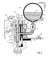
- free-jet filling system is part of a filling machine, such as a filling machine rotating design for free jet filling of bottles 1 or other containers with a liquid product.
- the filling system consists inter alia of a filling element 2, which with a plurality of similar filling elements 2 and associated with this bottle or container carriers 3, where the bottles to be filled 1 during filling at a mouth flange 1.1 are held suspended, is provided on the circumference of a circumferentially about a vertical axis of the machine drivable rotor 4.
- each filling element 2 u.a. a liquid channel 6 is formed, which is connected at its upper end via a line 7 with a flow meter 8 to a common boiler 4 for all filling elements 2 provided on the rotor.
- the boiler 9 is filled level controlled for the operation of the filling machine up to a level N with the liquid product, so that in the boiler 9 above the Gregutspiegels a gas chamber 9.1 and lying below a liquid chamber 9.2 are formed, in which the lines 7 open.
- the liquid channel 6 forms at the bottom a provided with a gas barrier 10 discharge opening 11, via which the liquid product flows during the free jet filling of the respective bottle 1 as a free jet 12, and at 1.2 spaced from the discharge opening 11 bottle mouth.
- a liquid valve 13 is provided in the flow direction of the filling in front of the gas barrier 10, which is formed in the illustrated embodiment by a valve stem in the form of a pipe section 14 with valve body 15 which cooperates with a valve seat in the liquid channel 6.
- the liquid valve 13 is opened and closed by an actuator 16 for a volume-controlled filling taking into account the signal of the flow meter 8.
- the channel formed in the interior of the pipe section 14 14.1 is open at the discharge opening 11 and surrounded by the gas barrier 10, which is formed in the illustrated embodiment of an annular insert with a plurality of parallel to each other and parallel to the axis FA oriented and open at both ends individual channels , Furthermore, the channel opens into a 14.1 formed in the housing 5 and outwardly closed control chamber 17 which is bounded at the top by a piston 18 and laterally by a pleated ball 19.
- the piston 18 is provided on the upper side of the housing 5 by means of a piston rod 20 in the direction of the axis FA by a predetermined maximum stroke axially displaceable.
- the led out of the housing 5 and with a cam roller 21st provided end 20.1 of the piston rod 20 is connected via a linkage with the container carrier 3.
- the container carrier 3 controlled against the action of a compression spring 22 can be lowered.
- the gas barrier 10 is provided, for example, on the pipe section 14 and movable with this opening and closing of the liquid valve 13 in the direction of the axis FA, or at the Golfelementgeophuse 5 firmly provided gas barrier 10, the pipe section 14 is arranged axially displaceable in the gas barrier 10 with its lower end or led.
- two flow channels 23 and 24 are formed inside the housing 5 of the filling element 2, of which the flow channel 23 has an electrically controllable valve 25 and thus a controlled connection between the control chamber 17 and one on the rotor 4 for all filling elements 2 Filling machine or a group of filling elements common annular channel 26 forms.
- the flow channel 24 is provided with a check valve 27 and connects the liquid channel 6 in the flow direction immediately before the liquid valve 19 and the valve seat of this liquid valve with a rotor 4 for all filling elements 2 or a group of filling elements 2 jointly provided annular channel 28.
- the check valve 27th is designed so that it opens for a flow from the liquid channel 6 into the annular channel 28, but blocks for a flow in the opposite direction. Via an electrically actuated valve 29, the two annular channels 26 and 28 can be controlled connected to each other or separated from each other.
- a line 30 is connected to a control valve 31.
- a piston or cylinder chamber 32 ( FIG. 2 ), which is controlled via an electrically actuated control valve 33 with the pressure of a compressed air source 34 acted upon.
- the cylinder chamber 32 can be pressurized, whereby the piston 18 is moved down into a lower stroke position, which is defined by the stop of the end 20.1 against the top of the housing 5. In this position, the piston 18 forms a stop for the upper end of the pipe section 14. This stop is adjusted so that the liquid valve 13 can be opened via the actuator 16 only with a reduced valve gap for a slower filling, ie for a slow filling this in the FIG. 2 is shown.
- the size of the valve gap of the liquid valve 13 and thus the volume flow of the liquid filling material in the slow filling phase can be adjusted by the positions of the piston 18 at pressurized cylinder chamber 32, for example by appropriate adjustment of the upper end 20.1 of the piston rod 20 and / or a housing-side stop for this end.
- the boiler 9 as well as the annular channel 28 and the line 30 with the open valve 31 is provided with a circulating and heating device for the liquid product cycle, in which the liquid, hot contents even with the liquid valve 13 closed each filling element 2 and the local fluid channel 6 via the line 7 flows and is returned from the liquid channel 6 via the flow channel 24, the annular channel 28 and the line 30 with the open valve 31 to the boiler 9.
- each annular seal 36 a flushing chamber 36 sealed to the outside is formed, into which the discharge opening 11 or the gas barrier 10, but also the lower, open end of the channel 14.1 open.
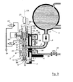
- the control valve 25 and the valves 29 and 31 and the liquid valve 13 are open at zero pressure cylinder chamber, so that the supplied from the boiler 9 via the lines 7 cleaning and sterilization medium according to the arrows A of FIG. 3 all channels of each filling element 2 as well as the annular channels 26 and 29, the line 30 and the control valves 25, 29 and 31 flows through.
- the cleaning and sterilization medium passes through the channel 14.1 in particular also into the control chamber 17, so that the respective, held on the container carrier 3 flushing plate 35 in addition to the pressure of the compression spring 22 and by the force exerted on the piston 18 pressure of the cleaning or sterilization medium the sealing opening 11 surrounding the edge 11.1 is pressed sealed.
- FIG. 4 shows as a further embodiment a filling element 2a, which differs from the filling element 2 essentially only in that in the flow channel 23 instead of the electrically controllable valve 25, a check valve 38 is provided, which opens for a flow from the control chamber 17 into the annular channel 26, for a flow in opposite direction but locks.
- the check valve 38 is also prevented during filling via the pipe section 14 or via the formed in this piece of pipe duct air is sucked with the leaking from the discharge opening 11 liquid product and it can thereby cause excessive foaming and / or excessive inclusion of air and thus oxygen in the bottled filling ,
- About the check valve 38 but required for the CIP cleaning and / or sterilization flow of the cleaning or sterilization medium in the flow channel 23 is possible.
Landscapes
- Filling Of Jars Or Cans And Processes For Cleaning And Sealing Jars (AREA)
Description
Die Erfindung bezieht sich auf ein Füllsystem gemäß Oberbegriff Patentanspruch 1 und wie aus der
Füllsysteme zur Verwendung bei Füllmaschinen zum Füllen von Flaschen oder dergleichen Behälter mit einem flüssigen Füllgut sind in unterschiedlichen Ausführungen bekannt. Bekannt ist auch, das jeweilige Füllelement an seiner Abgabeöffnung für eine Reinigung und/oder Sterilisation (CIP-Reinigung und/oder -Sterilisation) durch ein Verschließelement, beispielsweise durch eine Spülkappe oder Spülplatte, zu verschließen, und zwar unter Ausbildung einer von dem in der Regel flüssigen Reinigungs- und/oder Sterilisationsmedium durchströmbaren Spülkammer. Bekannt ist hierbei auch, im Füllelement einen mit einem Fluid-Druck beaufschlagbaren Steuerraum vorzusehen, in den ein im Bereich der Abgabeöffnung offener Fluidkanal mündet und der Bestandteil eines durch Druck betätigbaren Steuerelementes ist, mit dem u.a. das Verschließelement durch den Druck des Spül- und/oder Sterilisationsmediums im Steuerraum gegen das Füllelement dicht anpressbar ist. Diese sehr vorteilhafte Verfahrensweise ist bei Freistrahl-Füllsystemen bisher nicht anwendbar.Filling systems for use in filling machines for filling bottles or the like containers with a liquid product are known in different designs. It is also known to close the respective filling element at its discharge opening for cleaning and / or sterilization (CIP cleaning and / or sterilization) by a closing element, for example by a rinsing cap or rinsing plate, to form one of the in the Usually liquid cleaning and / or sterilization medium permeable flushing chamber. It is also known to provide in the filling element a controllable with a fluid pressure control chamber into which opens an open in the region of the discharge port fluid channel and is part of a controllable by pressure control element, with the u.a. the closing element can be pressed tightly against the filling element by the pressure of the rinsing and / or sterilizing medium in the control chamber. This very advantageous procedure is not applicable to free-jet filling systems.
Freistrahl-Füllsysteme im Sinne der Erfindung sind Füllsysteme, mit denen ein Füllen von Flaschen oder dergleichen Behälter in der Weise erfolgt, dass das flüssige Füllgut dem jeweiligen Behälter in einem freien Strahl zufließt.Free-jet filling systems in the context of the invention are filling systems with which a filling of bottles or similar containers takes place in such a way that the liquid filling material flows into the respective container in a free jet.
Aufgabe der Erfindung ist es, ein Freistrahl-Füllsystem aufzuzeigen, bei welchem während des Reinigungs- und/oder Sterilisationsbetriebes (CIP-Reinigung und/oder -Sterilisation) ein abgedichtetes Anpressen des Verschließelementes gegen das Füllelement durch den im Steuerraum herrschenden Druck des Reinigungs- bzw. Sterilisationsmedium möglich ist. Zur Lösung dieser Aufgabe ist ein Füllsystem entsprechend dem Patentanspruch 1 ausgebildet. Ein Verfahren zur Steuerung des Füllsystems ist Gegenstand der Patentansprüche 19 oder 21.The object of the invention is to provide a free-jet filling system in which during the cleaning and / or sterilization operation (CIP cleaning and / or sterilization) a sealed pressing of the closing element against the filling element by the pressure prevailing in the control chamber of the cleaning or Sterilization medium is possible. To solve this problem, a filling system according to the
Bei dem erfindungsgemäßen Füllsystem ist während des normalen Füllprozesses, d.h. während des Freistrahlfüllens der von dem Fluidkanal, dem Steuerraum und dem "ersten" Strömungskanal gebildete Gas- oder Strömungsweg geschlossen, sodass weder flüssiges Füllgut in diesen Gas- oder Strömungsweg eindringen kann, noch über diesen Gas- oder Strömungsweg Luft von dem aus der Abgabeöffnung austretenden flüssigen Füllgut angesaugt und mitgeführt werden kann. Während des Reinigungs- und/oder Sterilisationsbetriebes (CIP-Reinigung und/oder - Sterilisation) ist der vorgenannte Gas- oder Strömungsweg geöffnet, sodass hierdurch u.a. auch der Steuerraum von dem Reinigungs- und/oder Sterilisationsmedium durchströmt und zugleich durch den sich im Steuerraum aufbauenden Druck des Reinigungs- und/oder Sterilisationsmediums auch die erforderlichen Anpresskraft für das Verschließelement (z.B. Spülkappe oder Spülplatte) erzeugt wird.In the filling system according to the invention, during the normal filling process, ie during the free-jet filling, the gas or flow path formed by the fluid channel, the control chamber and the "first" flow channel is closed, so that neither liquid filling material can penetrate into this gas or flow path, nor air can be sucked and carried along by this gas or flow path from the liquid filling material emerging from the discharge opening. During the cleaning and / or sterilization operation (CIP cleaning and / or sterilization), the aforementioned gas or flow path is opened so that, inter alia, the control chamber also flows through the cleaning and / or sterilization medium and at the same time through the building in the control room Pressure of the cleaning and / or sterilization medium and the required contact force for the closing element (eg, rinse cap or dish) is generated.
Weiterbildungen, Vorteile und Anwendungsmöglichkeiten der Erfindung ergeben sich auch aus der nachfolgenden Beschreibung von Ausführungsbeispielen und aus den Figuren.Further developments, advantages and applications of the invention will become apparent from the following description of exemplary embodiments and from the figures.
Die Erfindung wird im Folgenden anhand der Figuren an Ausführungsbeispielen näher erläutert. Es zeigen:
- Fig. 1 und 2
- ein Freistrahl-Füllsystem gemäß der Erfindung in einem einer Schnellfüllphase bzw. einer Langsamfüllphase entsprechenden Betriebszustand;
- Fig. 3
- in einer Darstellung wie
Figur 1 - Fig. 4
- eine Darstellung
ähnlich Figur 2 bei einer weiteren Ausführungsform der Erfindung.
- Fig. 1 and 2
- a free jet filling system according to the invention in an operating state corresponding to a fast filling phase or a slow filling phase, respectively;
- Fig. 3
- in a presentation like
FIG. 1 but in an operating condition for CIP cleaning and / or sterilization; - Fig. 4
- a representation similar
FIG. 2 in a further embodiment of the invention.
Das in den
Im Gehäuse 5 jedes Füllelementes 2 ist u.a. ein Flüssigkeitskanal 6 ausgebildet, der mit seinem oberen Ende über eine Leitung 7 mit Durchflussmesser 8 an einen am Rotor 4 für sämtliche Füllelemente 2 gemeinsam vorgesehenen Kessel 9 angeschlossen ist. Der Kessel 9 ist für den Betrieb der Füllmaschine bis zu einem Niveau N niveaugesteuert mit dem flüssigen Füllgut gefüllt, sodass im Kessel 9 oberhalb des Füllgutspiegels ein Gasraum 9.1 und darunter liegend ein Flüssigkeitsraum 9.2 gebildet sind, in den die Leitungen 7 münden.In the
Der Flüssigkeitskanal 6 bildet an der Unterseite eine mit einer Gassperre 10 versehene Abgabeöffnung 11, über die das flüssige Füllgut während des Freistrahlfüllens der jeweiligen Flasche 1 als freier Strahl 12 zufließt, und zwar bei von der Abgabeöffnung 11 beabstandeter Flaschenmündung 1.2.The
Im Flüssigkeitskanal 6 ist in Strömungsrichtung des Füllgutes vor der Gassperre 10 ein Flüssigkeitsventil 13 vorgesehen, welches bei der dargestellten Ausführungsform von einem Ventilstößel in Form eines Rohrstücks 14 mit Ventilkörper 15 gebildet ist, der mit einem Ventilsitz im Flüssigkeitskanal 6 zusammenwirkt. Über das mit seiner Achse achsgleich mit der vertikalen Füllelementachse FA angeordnete und beidendig offene Rohrstück 14 wird das Flüssigkeitsventil 13 durch eine Betätigungseinrichtung 16 für ein volumengesteuertes Füllen unter Berücksichtigung des Signals des Durchflussmessers 8 geöffnet und geschlossen.In the
Der im Inneren des Rohrstückes 14 gebildete Kanal 14.1 ist an der Abgabeöffnung 11 offen und dort von der Gassperre 10 umgeben, die bei der dargestellten Ausführungsform von einem ringartigen Einsatz mit einer Vielzahl von parallel zueinander und parallel zur Achse FA orientierten und beidendig offenen Einzelkanälen gebildet ist. Weiterhin mündet der Kanal 14.1 in einen in dem Gehäuse 5 ausgebildeten und nach außen hin geschlossenen Steuerraum 17, der an der Oberseite durch einen Kolben 18 und seitlich durch einen Faltenball 19 begrenzt ist. Der Kolben 18 ist an der Oberseite des Gehäuses 5 mittels einer Kolbenstange 20 in Richtung der Achse FA um einen vorgegebenen maximalen Hub axial verschiebbar vorgesehen. Das aus dem Gehäuse 5 herausgeführte und mit einer Kurvenrolle 21 versehene Ende 20.1 der Kolbenstange 20 ist über ein Gestänge mit dem Behälterträger 3 verbunden. Über die Kurvenrolle 21 und eine nicht dargestellte Steuerkurve ist der Behälterträger 3 gegen die Wirkung einer Druckfeder 22 gesteuert absenkbar. Die Gassperre 10 ist z.B. am Rohrstück 14 vorgesehen und mit diesem Öffnen und Schließen des Flüssigkeitsventils 13 in Richtung der Achse FA beweglich, oder aber bei am Füllelementgehäuse 5 fest vorgesehener Gassperre 10 ist das Rohrstück 14 mit seinem unteren Ende axial verschiebbar in der Gassperre 10 angeordnet oder geführt.The channel formed in the interior of the
Im Inneren des Gehäuses 5 des Füllelementes 2 sind bei der dargestellten Ausführungsform zwei Strömungskanäle 23 und 24 ausgebildet, von denen der Strömungskanal 23 ein elektrisch steuerbares Ventil 25 aufweist und so eine gesteuerte Verbindung zwischen dem Steuerraum 17 und einem am Rotor 4 für sämtliche Füllelemente 2 der Füllmaschine oder aber einer Gruppe von Füllelementen gemeinsamen Ringkanal 26 bildet.In the illustrated embodiment, two
Der Strömungskanal 24 ist mit einem Rückschlagventil 27 versehen und verbindet den Flüssigkeitskanal 6 in Strömungsrichtung unmittelbar vor dem Flüssigkeitsventil 19 bzw. dem Ventilsitz dieses Flüssigkeitsventils mit einem am Rotor 4 für sämtlich Füllelemente 2 oder eine Gruppe von Füllelementen 2 gemeinsam vorgesehenen Ringkanal 28. Das Rückschlagventil 27 ist so ausgebildet, dass es für eine Strömung aus dem Flüssigkeitskanal 6 in den Ringkanal 28 öffnet, für eine Strömung in entgegen gesetzter Richtung aber sperrt. Über ein elektrisch betätigbares Ventil 29 können die beiden Ringkanäle 26 und 28 gesteuert miteinander verbunden bzw. voneinander getrennt werden. An dem Ringkanal 28 ist eine Leitung 30 mit einem Steuerventil 31 angeschlossen.The
Oberhalb des Kolbens 18 ist im Inneren des Gehäuses 5 ein Kolben- oder Zylinderraum 32 (
Mit dem Füllsystem bzw. Füllelement 2 sind unterschiedlichste Verfahrensweisen möglich.With the filling system or filling
Zunächst ist in der in der
Durch Betätigen des Steuerventils 33 kann der Zylinderraum 32 mit Druck beaufschlagt werden, wodurch der Kolben 18 nach unten in eine untere Hubstellung bewegt wird, die durch den Anschlag des Endes 20.1 gegen die Oberseite des Gehäuses 5 definiert ist. Der Kolben 18 bildet in dieser Stellung einen Anschlag für das obere Ende des Rohrstückes 14. Dieser Anschlag ist so eingestellt, dass das Flüssigkeitsventil 13 über das Betätigungselement 16 nur mit einem reduzierten Ventilspalt für ein verlangsamtes Füllen, d.h. für eine Langsamfüllphase geöffnet werden kann, wie dies in der
Dadurch, dass der Strömungskanal 23 durch das Steuerventil 25 geschlossen ist, kann während des Füllen kein flüssiges Füllgut in den Kanal 14.1 eindringen und/oder aus dem Kanal 14.1 Luft von dem flüssigen Füllgut angesaugt und mitgeführt werden. Hierdurch ist beim Füllen u.a. eine übermäßige Schaumbildung sowie auch verhindert, dass es zu einem übermäßigen Einschluss von Luft und damit Sauerstoff in dem abgefüllten Füllgut kommt.Characterized in that the
Durch die beschriebene Ausbildung ist weiterhin ein Warmhalten oder Heizen der Füllelemente 2 in Füllpausen, insbesondere auch während der Zeit zwischen der Beendigung einer Füllphase und der Beginn einer neuen Füllphase möglich, und zwar durch einen Umlauf eines heißen, flüssigen Füllgutes (Heißumlauf). Hierfür bildet der Kessel 9 sowie auch der Ringkanal 28 und die Leitung 30 mit dem geöffneten Ventil 31 einen mit eine Umwälz- und Heizeinrichtung für das flüssige Füllgut versehenen Kreislauf, in welchem das flüssige, heiße Füllgut auch bei geschlossenem Flüssigkeitsventil 13 jedem Füllelement 2 bzw. dem dortigen Flüssigkeitskanal 6 über die Leitung 7 zufließt und aus dem Flüssigkeitskanal 6 über den Strömungskanal 24, den Ringkanal 28 und die Leitung 30 mit dem geöffneten Ventil 31 an den Kessel 9 zurückgeleitet wird.Due to the described configuration, it is furthermore possible to keep the
Mit der beschriebenen Ausbildung ist insbesondere aber auch eine Reinigung und Sterilisation aller Kanäle sämtlicher Füllelemente der Füllmaschine einschließlich der Ringkanäle 26 und 28 und der Leitung 30 möglich (
Die
Claims (24)
- A free-jet filling system for filling machines for filling bottles or similar containers (1) with a liquid bulk product, having a filling element (2), in the housing (5) of which a fluid channel is provided controlled by at least one fluid valve (13) and forming at least one dispensing opening (11), with a bracket (3) to which a closing element (35) closing the dispensing opening (11) for a cleaning and / or sterilisation operation is fixed or can be fixed, and with means to press the closing element (35) against the filling element (2), characterised in that in the fluid channel in the direction of flow of the liquid bulk product, during filling, after the at least one fluid valve (13) at least one gas trap (10) through which liquid bulk product flows during filling is arranged, and in that the means to press the closing element (35) are formed by a control element (18) with a control chamber (17) which can be exposed to the application of fluid pressure, whereby a fluid channel (14.1) open in the area of the dispensing opening (11) opens into said control chamber, and in that in the filling element housing (5) at least a first controlled flow path including the fluid channel (14.1) and the control chamber (17) is formed, wherein said flow path leads to a first collector channel (26) jointly for the filling elements (2) or plurality of filling elements (2) of the filling machine and can be locked during the filling operation and opened during the cleaning and / or sterilisation operation.
- Filling system according to claim 1 characterised in that the control chamber (17) is limited by at least one piston (18) mounted moveably in the housing (5), able to be exposed to application of the pressure in the control chamber, and connected to the bracket (3).
- Filling system according to claim 1 or 2, characterised in that in the first flow path or in a flow channel (23), connecting the control chamber (17) to the first collector channel (26), of this flow path a controlling valve (25, 38) is provided.
- Filling system according to claim 3, characterised in that the valve provided in the first flow path or flow channel (23), is a controllable control valve (25) or a check valve (38), which opens for a flow into the first collector channel (26) and locks for a flow in the other direction.
- Filling system according to any one of the preceding claims, characterised in that the fluid channel (14.1) is formed in a valve plunger of the at least one fluid valve (13).
- Filling system according to any one of the preceding claims, characterised in that the fluid channel (14.1) is formed in a pipe section (14) preferably forming the valve plunger of the at least one filling element (13).
- Filling system according to any one of the preceding claims, characterised in that the fluid channel (14.1) is open in the area of the gas trap (10).
- Filling system according to any one of the preceding claims, characterised by at least a second controlled flow path (24) in the filling element (5), which connects the fluid channel (6) in the direction of flow of the liquid bulk product before the closed fluid valve (13) to a second collector channel (28) jointly for the filling elements (2) or for a plurality of filling elements (2) of the filling machine.
- Filling system according to claim 8, characterised in that the second flow path (24) is controlled in such a way that, during the cleaning and / or sterilisation operation and / or where the filling element (2) is heated with the hot bulk product, it opens for a flow from the fluid channel (6) into the second collector channel (28).
- Filling system according to claim 8 or 9, characterised in that in the second flow channel (24), a check valve (27) is provided which opens for a flow from the fluid channel (5) into the second collector channel (28), but stops a flow in the opposite direction.
- Filling system according to any one of the preceding claims characterised by a valve plunger end-stop (18), which can be controllably moved between an inactive position and an active position, and which, in the active position, limits the stroke of the valve plunger for a reduced opening of the fluid valve (13).
- Filling system according to claim 11 characterised in that the valve plunger end-stop (18) is pressure-controlled, i.e. is pneumatically moveable between its active and inactive position.
- Filling system according to claim 11 or 12, characterised in that in the valve plunger end-stop for the valve plunger extending into the control chamber (17) or for the pipe section (14) forming this valve plunger is formed by the piston (18) limiting the control chamber.
- Filling system according to claim 13, characterised in that the piston (18), on its side turned away from the control chamber (17), forms a control or cylinder chamber (32) to which a control pressure, preferably an air pressure, can be applied.
- Filling system according to claim 8 characterised by at least one controllable valve (29) connecting the first and second collector channel (26, 28).
- Filling system according to any one of the preceding claims, characterised in that the closing element (35) is provided moveably to the bracket (3), for example it can be shifted between a usage position and a non-usage position.
- Filling system according to any one of the preceding claims, characterised in that the closing element (3) is provided on a container bracket (3).
- Filling system according to any one of the preceding claims, characterised in that the closing element is a rinsing plate (35), preferably a rinsing plate (35) with at least one annular seal (36) which can press against the filling element (2) and which limits the rinsing chamber (37) at the side.
- Method for controlling a free-jet filling system according to any one of the preceding claims characterised in that, for the filling operation, the first flow path (14.1, 17, 23) is closed at least for a flow from the first collector channel (26).
- Method according to claim 19, characterised in that, for the filling operation, the first flow path (14.1, 17, 23) is closed at least for a flow from the first collector channel (26) into the control chamber (17).
- Method for controlling a filling system according to any one of claims 1 to 18, characterised in that, for a cleaning and / or sterilisation operation, with the filling element (2) closed by the closing element (35) on the dispensing opening (11) and with the fluid valve (13) open, the first flow path (14.1, 17, 23) is open at least for a flow of a cleaning and / or sterilisation medium through the control chamber (17) into the first collector channel (26), so that the closing element (35) is pressed against the filling element (2) by the pressure of the cleaning or sterilisation medium in the control chamber (17).
- Method according to claim 21 characterised in that, for the cleaning and / or sterilisation operation, the first collector channel (26) is connected to a second collector channel (28) for a flow of the cleaning and / or sterilisation medium.
- Method according to any one of preceding claims 21, 22, characterised in that during the cleaning and / or sterilisation operation, the cleaning or sterilisation medium supplied to the fluid channel (6) flows through at least this fluid channel, the gas trap (10), the rinsing chamber (37) limited by the closing element (35), the fluid channel (14.1), the control chamber (17) and the first flow channel (23) and is removed through the first or second collector channel (26, 28).
- Method according to claim 23 characterised in that, during the cleaning and / or sterilisation operation, the cleaning and / or sterilisation medium supplied to the fluid channel (6) also flows through the second flow path (24) and is removed by means of the second collector channel (28).
Priority Applications (2)
| Application Number | Priority Date | Filing Date | Title |
|---|---|---|---|
| SI200831059T SI2146922T1 (en) | 2007-05-09 | 2008-04-26 | Filling system and method for controlling a filling system |
| PL08749177T PL2146922T3 (en) | 2007-05-09 | 2008-04-26 | Filling system and method for controlling a filling system |
Applications Claiming Priority (2)
| Application Number | Priority Date | Filing Date | Title |
|---|---|---|---|
| DE102007022259A DE102007022259A1 (en) | 2007-05-09 | 2007-05-09 | Filling system and method for controlling a filling system |
| PCT/EP2008/003403 WO2008138472A1 (en) | 2007-05-09 | 2008-04-26 | Filling system and method for controlling a filling system |
Publications (2)
| Publication Number | Publication Date |
|---|---|
| EP2146922A1 EP2146922A1 (en) | 2010-01-27 |
| EP2146922B1 true EP2146922B1 (en) | 2013-07-03 |
Family
ID=39671778
Family Applications (1)
| Application Number | Title | Priority Date | Filing Date |
|---|---|---|---|
| EP08749177.5A Not-in-force EP2146922B1 (en) | 2007-05-09 | 2008-04-26 | Filling system and method for controlling a filling system |
Country Status (6)
| Country | Link |
|---|---|
| US (1) | US8776842B2 (en) |
| EP (1) | EP2146922B1 (en) |
| DE (1) | DE102007022259A1 (en) |
| PL (1) | PL2146922T3 (en) |
| SI (1) | SI2146922T1 (en) |
| WO (1) | WO2008138472A1 (en) |
Families Citing this family (21)
| Publication number | Priority date | Publication date | Assignee | Title |
|---|---|---|---|---|
| DE102007014702B4 (en) * | 2007-03-23 | 2017-03-30 | Khs Gmbh | Filling system for hot filling |
| DE102009016084A1 (en) * | 2009-04-03 | 2011-05-12 | Khs Gmbh | Filling element for filling containers with a liquid product, filling machine and method for filling containers |
| DE102009051160A1 (en) * | 2009-10-29 | 2011-05-05 | Khs Gmbh | Filling element and filling machine for filling containers |
| DE102010027512A1 (en) * | 2010-07-16 | 2012-01-19 | Khs Gmbh | Filling element, method and filling system for filling containers |
| DE102010047883A1 (en) * | 2010-10-11 | 2012-04-12 | Khs Gmbh | Method and filling system for volume and / or quantity-controlled filling of containers |
| DE102011017263A1 (en) * | 2011-04-15 | 2012-10-18 | Khs Gmbh | filler |
| DE102011112925A1 (en) * | 2011-09-13 | 2013-03-14 | Khs Gmbh | Method, filling system and filling element for filling containers |
| DE102011120164A1 (en) * | 2011-12-06 | 2013-06-06 | Khs Gmbh | Filling element and filling system |
| ITTO20111234A1 (en) * | 2011-12-29 | 2013-06-30 | Sidel Spa Con Socio Unico | FILLING DEVICE AND ITS CONTROL METHOD |
| ITTO20120240A1 (en) * | 2012-03-19 | 2013-09-20 | Sidel Spa Con Socio Unico | FILLING DEVICE |
| ITMI20131163A1 (en) * | 2013-07-10 | 2015-01-11 | Smi Spa | FILLING DEVICE |
| DE102013113621A1 (en) * | 2013-12-06 | 2015-06-11 | Krones Ag | Filling member for filling a filling product into a container and method for cleaning the filling member |
| DE102014109589A1 (en) * | 2014-07-09 | 2016-01-14 | Khs Gmbh | Filling system for filling bottles or similar containers |
| DE102014109809B4 (en) | 2014-07-14 | 2016-04-07 | Khs Gmbh | filling device |
| DE102015122033A1 (en) * | 2015-12-16 | 2017-06-22 | Khs Gmbh | filling |
| IT201800009471A1 (en) * | 2018-10-16 | 2020-04-16 | Sacmi Beverage Spa | FILLING MACHINE FOR HOT FILLING. |
| JP6729661B2 (en) * | 2018-10-31 | 2020-07-22 | 大日本印刷株式会社 | Method and apparatus for cleaning heat sterilization system |
| DE102019128153A1 (en) * | 2019-10-18 | 2021-04-22 | Krones Ag | Cleaning validation in a device for filling containers |
| DE102020110140A1 (en) * | 2020-04-14 | 2021-10-14 | Krones Aktiengesellschaft | Filling element with conversion from free jet to sieve outlet |
| US20230159316A1 (en) * | 2020-05-15 | 2023-05-25 | Dai Nippon Printing Co., Ltd. | Cleaning and sterilizing method for aseptic filling machine and aseptic filling machine |
| CN113493005B (en) * | 2021-07-29 | 2022-10-28 | 陕西祈飞实业有限公司 | Cosmetic preparation process |
Family Cites Families (11)
| Publication number | Priority date | Publication date | Assignee | Title |
|---|---|---|---|---|
| DE4231114A1 (en) * | 1992-09-17 | 1994-03-24 | Seitz Enzinger Noll Masch | Device for filling bottles or similar containers |
| DE10061401A1 (en) * | 2000-12-09 | 2002-06-13 | Khs Masch & Anlagenbau Ag | Method and appliance for filling containers comprise filler elements, liquid path, and control valves |
| DE10359779B4 (en) * | 2003-12-19 | 2006-03-16 | Khs Maschinen- Und Anlagenbau Ag | Filling element of a filling machine |
| DE102004004331B3 (en) * | 2004-01-29 | 2005-09-15 | Khs Maschinen- Und Anlagenbau Ag | Process for hot filling of a liquid filling material into bottles or the like container and filling machine for carrying out the method |
| DE102004011101B4 (en) * | 2004-03-06 | 2011-04-07 | Khs Gmbh | Filling elements and filling machine with such filling elements |
| DE102004015167B3 (en) * | 2004-03-27 | 2005-11-03 | Khs Maschinen- Und Anlagenbau Ag | filler |
| DE102004017205A1 (en) * | 2004-04-10 | 2005-10-27 | Khs Maschinen- Und Anlagenbau Ag | Filling machine of rotating design |
| DE102005037127B4 (en) * | 2005-08-06 | 2007-09-06 | Khs Ag | Filling element with rinsing cap |
| DE102006017706A1 (en) * | 2006-04-15 | 2007-10-25 | Khs Ag | Filling elements and filling machine with a filling element |
| FR2911595B1 (en) * | 2007-01-22 | 2011-04-08 | Sidel Participations | FILLING MACHINE EQUIPPED WITH A CLEANING DEVICE |
| FR2911594B1 (en) * | 2007-01-22 | 2009-04-03 | Sidel Participations | FILLING MACHINE EQUIPPED WITH A CLEANING DEVICE WITH DEFORMABLE MEMBRANE |
-
2007
- 2007-05-09 DE DE102007022259A patent/DE102007022259A1/en not_active Withdrawn
-
2008
- 2008-04-26 WO PCT/EP2008/003403 patent/WO2008138472A1/en active Application Filing
- 2008-04-26 EP EP08749177.5A patent/EP2146922B1/en not_active Not-in-force
- 2008-04-26 PL PL08749177T patent/PL2146922T3/en unknown
- 2008-04-26 SI SI200831059T patent/SI2146922T1/en unknown
-
2009
- 2009-11-06 US US12/614,296 patent/US8776842B2/en not_active Expired - Fee Related
Also Published As
| Publication number | Publication date |
|---|---|
| EP2146922A1 (en) | 2010-01-27 |
| DE102007022259A1 (en) | 2009-01-15 |
| US20100108180A1 (en) | 2010-05-06 |
| US8776842B2 (en) | 2014-07-15 |
| WO2008138472A1 (en) | 2008-11-20 |
| SI2146922T1 (en) | 2013-11-29 |
| PL2146922T3 (en) | 2013-12-31 |
Similar Documents
| Publication | Publication Date | Title |
|---|---|---|
| EP2146922B1 (en) | Filling system and method for controlling a filling system | |
| EP2010447B1 (en) | Filling element and filling machine with a filling element | |
| EP2162382B1 (en) | Filling system | |
| EP2879961B1 (en) | Filling element and filling machine | |
| EP2125600B1 (en) | Method for filling bottles or similar containers with a liquid product under counterpressure and filling machine for carrying out this method | |
| EP1580160B1 (en) | Filling head for counter pressure filling and free jet filling | |
| EP2029469B1 (en) | Filling element and filling machine comprising corresponding filling elements | |
| EP2132130B1 (en) | Filling system for hot-filling | |
| EP2969894B1 (en) | Method and filling machine for filling cans or the like containers with liquid contents | |
| WO2011050958A1 (en) | Filling element and filling machine for filling containers | |
| EP2882678B1 (en) | Multiple filling element for a filling system or a filling machine and filling machine | |
| EP2129612A2 (en) | Free-flow filling system with weighing cell | |
| WO2016066275A2 (en) | Piston arrangement for pumping a liquid | |
| WO2010000359A1 (en) | Filling element and filling machine for filling containers | |
| DE2947035C2 (en) | Filling element for counter pressure vessel filling machine | |
| DE102015116532A1 (en) | Method and treatment station and treatment head for treating the interiors of KEGs and seal for use in such a treatment station | |
| EP2534089B1 (en) | Filling system for filling containers in a pressurized manner | |
| EP1739051A1 (en) | Filling head and filling machine of the rotary type | |
| EP2958850A1 (en) | Filling system | |
| DE202012007517U1 (en) | Multiple filling element for a filling system or a filling machine and filling machine | |
| DE102012015962A1 (en) | Filling machine for filling containers with liquid product, has fillers that are intended to be mounted on underside of rotor for supplying liquid filling in ring boiler |
Legal Events
| Date | Code | Title | Description |
|---|---|---|---|
| PUAI | Public reference made under article 153(3) epc to a published international application that has entered the european phase |
Free format text: ORIGINAL CODE: 0009012 |
|
| 17P | Request for examination filed |
Effective date: 20091209 |
|
| AK | Designated contracting states |
Kind code of ref document: A1 Designated state(s): AT BE BG CH CY CZ DE DK EE ES FI FR GB GR HR HU IE IS IT LI LT LU LV MC MT NL NO PL PT RO SE SI SK TR |
|
| AX | Request for extension of the european patent |
Extension state: AL BA MK RS |
|
| RAP1 | Party data changed (applicant data changed or rights of an application transferred) |
Owner name: KHS GMBH |
|
| DAX | Request for extension of the european patent (deleted) | ||
| GRAP | Despatch of communication of intention to grant a patent |
Free format text: ORIGINAL CODE: EPIDOSNIGR1 |
|
| GRAS | Grant fee paid |
Free format text: ORIGINAL CODE: EPIDOSNIGR3 |
|
| GRAA | (expected) grant |
Free format text: ORIGINAL CODE: 0009210 |
|
| AK | Designated contracting states |
Kind code of ref document: B1 Designated state(s): AT BE BG CH CY CZ DE DK EE ES FI FR GB GR HR HU IE IS IT LI LT LU LV MC MT NL NO PL PT RO SE SI SK TR |
|
| REG | Reference to a national code |
Ref country code: GB Ref legal event code: FG4D Free format text: NOT ENGLISH |
|
| REG | Reference to a national code |
Ref country code: AT Ref legal event code: REF Ref document number: 619625 Country of ref document: AT Kind code of ref document: T Effective date: 20130715 Ref country code: CH Ref legal event code: EP |
|
| REG | Reference to a national code |
Ref country code: IE Ref legal event code: FG4D Free format text: LANGUAGE OF EP DOCUMENT: GERMAN |
|
| REG | Reference to a national code |
Ref country code: DE Ref legal event code: R096 Ref document number: 502008010233 Country of ref document: DE Effective date: 20130829 |
|
| REG | Reference to a national code |
Ref country code: NL Ref legal event code: VDEP Effective date: 20130703 |
|
| REG | Reference to a national code |
Ref country code: LT Ref legal event code: MG4D |
|
| REG | Reference to a national code |
Ref country code: PL Ref legal event code: T3 |
|
| PG25 | Lapsed in a contracting state [announced via postgrant information from national office to epo] |
Ref country code: PT Free format text: LAPSE BECAUSE OF FAILURE TO SUBMIT A TRANSLATION OF THE DESCRIPTION OR TO PAY THE FEE WITHIN THE PRESCRIBED TIME-LIMIT Effective date: 20131104 Ref country code: LT Free format text: LAPSE BECAUSE OF FAILURE TO SUBMIT A TRANSLATION OF THE DESCRIPTION OR TO PAY THE FEE WITHIN THE PRESCRIBED TIME-LIMIT Effective date: 20130703 Ref country code: HR Free format text: LAPSE BECAUSE OF FAILURE TO SUBMIT A TRANSLATION OF THE DESCRIPTION OR TO PAY THE FEE WITHIN THE PRESCRIBED TIME-LIMIT Effective date: 20130703 Ref country code: SE Free format text: LAPSE BECAUSE OF FAILURE TO SUBMIT A TRANSLATION OF THE DESCRIPTION OR TO PAY THE FEE WITHIN THE PRESCRIBED TIME-LIMIT Effective date: 20130703 Ref country code: IS Free format text: LAPSE BECAUSE OF FAILURE TO SUBMIT A TRANSLATION OF THE DESCRIPTION OR TO PAY THE FEE WITHIN THE PRESCRIBED TIME-LIMIT Effective date: 20131103 Ref country code: CY Free format text: LAPSE BECAUSE OF FAILURE TO SUBMIT A TRANSLATION OF THE DESCRIPTION OR TO PAY THE FEE WITHIN THE PRESCRIBED TIME-LIMIT Effective date: 20130814 Ref country code: NO Free format text: LAPSE BECAUSE OF FAILURE TO SUBMIT A TRANSLATION OF THE DESCRIPTION OR TO PAY THE FEE WITHIN THE PRESCRIBED TIME-LIMIT Effective date: 20131003 |
|
| PG25 | Lapsed in a contracting state [announced via postgrant information from national office to epo] |
Ref country code: ES Free format text: LAPSE BECAUSE OF FAILURE TO SUBMIT A TRANSLATION OF THE DESCRIPTION OR TO PAY THE FEE WITHIN THE PRESCRIBED TIME-LIMIT Effective date: 20131014 Ref country code: LV Free format text: LAPSE BECAUSE OF FAILURE TO SUBMIT A TRANSLATION OF THE DESCRIPTION OR TO PAY THE FEE WITHIN THE PRESCRIBED TIME-LIMIT Effective date: 20130703 Ref country code: GR Free format text: LAPSE BECAUSE OF FAILURE TO SUBMIT A TRANSLATION OF THE DESCRIPTION OR TO PAY THE FEE WITHIN THE PRESCRIBED TIME-LIMIT Effective date: 20131004 Ref country code: FI Free format text: LAPSE BECAUSE OF FAILURE TO SUBMIT A TRANSLATION OF THE DESCRIPTION OR TO PAY THE FEE WITHIN THE PRESCRIBED TIME-LIMIT Effective date: 20130703 Ref country code: NL Free format text: LAPSE BECAUSE OF FAILURE TO SUBMIT A TRANSLATION OF THE DESCRIPTION OR TO PAY THE FEE WITHIN THE PRESCRIBED TIME-LIMIT Effective date: 20130703 |
|
| PG25 | Lapsed in a contracting state [announced via postgrant information from national office to epo] |
Ref country code: CY Free format text: LAPSE BECAUSE OF FAILURE TO SUBMIT A TRANSLATION OF THE DESCRIPTION OR TO PAY THE FEE WITHIN THE PRESCRIBED TIME-LIMIT Effective date: 20130703 |
|
| PG25 | Lapsed in a contracting state [announced via postgrant information from national office to epo] |
Ref country code: EE Free format text: LAPSE BECAUSE OF FAILURE TO SUBMIT A TRANSLATION OF THE DESCRIPTION OR TO PAY THE FEE WITHIN THE PRESCRIBED TIME-LIMIT Effective date: 20130703 Ref country code: SK Free format text: LAPSE BECAUSE OF FAILURE TO SUBMIT A TRANSLATION OF THE DESCRIPTION OR TO PAY THE FEE WITHIN THE PRESCRIBED TIME-LIMIT Effective date: 20130703 Ref country code: CZ Free format text: LAPSE BECAUSE OF FAILURE TO SUBMIT A TRANSLATION OF THE DESCRIPTION OR TO PAY THE FEE WITHIN THE PRESCRIBED TIME-LIMIT Effective date: 20130703 Ref country code: RO Free format text: LAPSE BECAUSE OF FAILURE TO SUBMIT A TRANSLATION OF THE DESCRIPTION OR TO PAY THE FEE WITHIN THE PRESCRIBED TIME-LIMIT Effective date: 20130703 Ref country code: DK Free format text: LAPSE BECAUSE OF FAILURE TO SUBMIT A TRANSLATION OF THE DESCRIPTION OR TO PAY THE FEE WITHIN THE PRESCRIBED TIME-LIMIT Effective date: 20130703 |
|
| PLBE | No opposition filed within time limit |
Free format text: ORIGINAL CODE: 0009261 |
|
| STAA | Information on the status of an ep patent application or granted ep patent |
Free format text: STATUS: NO OPPOSITION FILED WITHIN TIME LIMIT |
|
| 26N | No opposition filed |
Effective date: 20140404 |
|
| REG | Reference to a national code |
Ref country code: DE Ref legal event code: R097 Ref document number: 502008010233 Country of ref document: DE Effective date: 20140404 |
|
| PG25 | Lapsed in a contracting state [announced via postgrant information from national office to epo] |
Ref country code: MC Free format text: LAPSE BECAUSE OF FAILURE TO SUBMIT A TRANSLATION OF THE DESCRIPTION OR TO PAY THE FEE WITHIN THE PRESCRIBED TIME-LIMIT Effective date: 20130703 Ref country code: LU Free format text: LAPSE BECAUSE OF FAILURE TO SUBMIT A TRANSLATION OF THE DESCRIPTION OR TO PAY THE FEE WITHIN THE PRESCRIBED TIME-LIMIT Effective date: 20140426 |
|
| REG | Reference to a national code |
Ref country code: CH Ref legal event code: PL |
|
| REG | Reference to a national code |
Ref country code: IE Ref legal event code: MM4A |
|
| PG25 | Lapsed in a contracting state [announced via postgrant information from national office to epo] |
Ref country code: LI Free format text: LAPSE BECAUSE OF NON-PAYMENT OF DUE FEES Effective date: 20140430 Ref country code: CH Free format text: LAPSE BECAUSE OF NON-PAYMENT OF DUE FEES Effective date: 20140430 |
|
| PG25 | Lapsed in a contracting state [announced via postgrant information from national office to epo] |
Ref country code: IE Free format text: LAPSE BECAUSE OF NON-PAYMENT OF DUE FEES Effective date: 20140426 |
|
| PG25 | Lapsed in a contracting state [announced via postgrant information from national office to epo] |
Ref country code: MT Free format text: LAPSE BECAUSE OF FAILURE TO SUBMIT A TRANSLATION OF THE DESCRIPTION OR TO PAY THE FEE WITHIN THE PRESCRIBED TIME-LIMIT Effective date: 20130703 |
|
| REG | Reference to a national code |
Ref country code: FR Ref legal event code: PLFP Year of fee payment: 9 |
|
| PG25 | Lapsed in a contracting state [announced via postgrant information from national office to epo] |
Ref country code: BG Free format text: LAPSE BECAUSE OF FAILURE TO SUBMIT A TRANSLATION OF THE DESCRIPTION OR TO PAY THE FEE WITHIN THE PRESCRIBED TIME-LIMIT Effective date: 20130703 |
|
| PG25 | Lapsed in a contracting state [announced via postgrant information from national office to epo] |
Ref country code: TR Free format text: LAPSE BECAUSE OF FAILURE TO SUBMIT A TRANSLATION OF THE DESCRIPTION OR TO PAY THE FEE WITHIN THE PRESCRIBED TIME-LIMIT Effective date: 20130703 Ref country code: HU Free format text: LAPSE BECAUSE OF FAILURE TO SUBMIT A TRANSLATION OF THE DESCRIPTION OR TO PAY THE FEE WITHIN THE PRESCRIBED TIME-LIMIT; INVALID AB INITIO Effective date: 20080426 Ref country code: BE Free format text: LAPSE BECAUSE OF FAILURE TO SUBMIT A TRANSLATION OF THE DESCRIPTION OR TO PAY THE FEE WITHIN THE PRESCRIBED TIME-LIMIT Effective date: 20140430 |
|
| REG | Reference to a national code |
Ref country code: FR Ref legal event code: PLFP Year of fee payment: 10 |
|
| REG | Reference to a national code |
Ref country code: FR Ref legal event code: PLFP Year of fee payment: 11 |
|
| PGFP | Annual fee paid to national office [announced via postgrant information from national office to epo] |
Ref country code: PL Payment date: 20180322 Year of fee payment: 11 |
|
| PGFP | Annual fee paid to national office [announced via postgrant information from national office to epo] |
Ref country code: DE Payment date: 20180420 Year of fee payment: 11 |
|
| PGFP | Annual fee paid to national office [announced via postgrant information from national office to epo] |
Ref country code: IT Payment date: 20180423 Year of fee payment: 11 Ref country code: SI Payment date: 20180403 Year of fee payment: 11 Ref country code: FR Payment date: 20180420 Year of fee payment: 11 Ref country code: AT Payment date: 20180419 Year of fee payment: 11 |
|
| PGFP | Annual fee paid to national office [announced via postgrant information from national office to epo] |
Ref country code: GB Payment date: 20180418 Year of fee payment: 11 |
|
| REG | Reference to a national code |
Ref country code: DE Ref legal event code: R119 Ref document number: 502008010233 Country of ref document: DE |
|
| REG | Reference to a national code |
Ref country code: AT Ref legal event code: MM01 Ref document number: 619625 Country of ref document: AT Kind code of ref document: T Effective date: 20190426 |
|
| GBPC | Gb: european patent ceased through non-payment of renewal fee |
Effective date: 20190426 |
|
| PG25 | Lapsed in a contracting state [announced via postgrant information from national office to epo] |
Ref country code: AT Free format text: LAPSE BECAUSE OF NON-PAYMENT OF DUE FEES Effective date: 20190426 Ref country code: GB Free format text: LAPSE BECAUSE OF NON-PAYMENT OF DUE FEES Effective date: 20190426 Ref country code: DE Free format text: LAPSE BECAUSE OF NON-PAYMENT OF DUE FEES Effective date: 20191101 |
|
| PG25 | Lapsed in a contracting state [announced via postgrant information from national office to epo] |
Ref country code: SI Free format text: LAPSE BECAUSE OF NON-PAYMENT OF DUE FEES Effective date: 20190427 Ref country code: FR Free format text: LAPSE BECAUSE OF NON-PAYMENT OF DUE FEES Effective date: 20190430 |
|
| PG25 | Lapsed in a contracting state [announced via postgrant information from national office to epo] |
Ref country code: IT Free format text: LAPSE BECAUSE OF NON-PAYMENT OF DUE FEES Effective date: 20190426 |
|
| PG25 | Lapsed in a contracting state [announced via postgrant information from national office to epo] |
Ref country code: PL Free format text: LAPSE BECAUSE OF NON-PAYMENT OF DUE FEES Effective date: 20190426 |