EP2010447B1 - Filling element and filling machine with a filling element - Google Patents
Filling element and filling machine with a filling element Download PDFInfo
- Publication number
- EP2010447B1 EP2010447B1 EP07723939A EP07723939A EP2010447B1 EP 2010447 B1 EP2010447 B1 EP 2010447B1 EP 07723939 A EP07723939 A EP 07723939A EP 07723939 A EP07723939 A EP 07723939A EP 2010447 B1 EP2010447 B1 EP 2010447B1
- Authority
- EP
- European Patent Office
- Prior art keywords
- filling
- filling element
- valve
- liquid
- element according
- Prior art date
- Legal status (The legal status is an assumption and is not a legal conclusion. Google has not performed a legal analysis and makes no representation as to the accuracy of the status listed.)
- Active
Links
Images


Classifications
-
- B—PERFORMING OPERATIONS; TRANSPORTING
- B67—OPENING, CLOSING OR CLEANING BOTTLES, JARS OR SIMILAR CONTAINERS; LIQUID HANDLING
- B67C—CLEANING, FILLING WITH LIQUIDS OR SEMILIQUIDS, OR EMPTYING, OF BOTTLES, JARS, CANS, CASKS, BARRELS, OR SIMILAR CONTAINERS, NOT OTHERWISE PROVIDED FOR; FUNNELS
- B67C3/00—Bottling liquids or semiliquids; Filling jars or cans with liquids or semiliquids using bottling or like apparatus; Filling casks or barrels with liquids or semiliquids
- B67C3/001—Cleaning of filling devices
- B67C3/002—Cleaning of filling devices using cups or dummies to be placed under the filling heads
- B67C3/004—Cleaning of filling devices using cups or dummies to be placed under the filling heads permanently attached to the filling machine and movable between a rest and a working position
-
- B—PERFORMING OPERATIONS; TRANSPORTING
- B67—OPENING, CLOSING OR CLEANING BOTTLES, JARS OR SIMILAR CONTAINERS; LIQUID HANDLING
- B67C—CLEANING, FILLING WITH LIQUIDS OR SEMILIQUIDS, OR EMPTYING, OF BOTTLES, JARS, CANS, CASKS, BARRELS, OR SIMILAR CONTAINERS, NOT OTHERWISE PROVIDED FOR; FUNNELS
- B67C3/00—Bottling liquids or semiliquids; Filling jars or cans with liquids or semiliquids using bottling or like apparatus; Filling casks or barrels with liquids or semiliquids
- B67C3/02—Bottling liquids or semiliquids; Filling jars or cans with liquids or semiliquids using bottling or like apparatus
- B67C3/023—Filling multiple liquids in a container
-
- B—PERFORMING OPERATIONS; TRANSPORTING
- B67—OPENING, CLOSING OR CLEANING BOTTLES, JARS OR SIMILAR CONTAINERS; LIQUID HANDLING
- B67C—CLEANING, FILLING WITH LIQUIDS OR SEMILIQUIDS, OR EMPTYING, OF BOTTLES, JARS, CANS, CASKS, BARRELS, OR SIMILAR CONTAINERS, NOT OTHERWISE PROVIDED FOR; FUNNELS
- B67C3/00—Bottling liquids or semiliquids; Filling jars or cans with liquids or semiliquids using bottling or like apparatus; Filling casks or barrels with liquids or semiliquids
- B67C3/02—Bottling liquids or semiliquids; Filling jars or cans with liquids or semiliquids using bottling or like apparatus
- B67C3/20—Bottling liquids or semiliquids; Filling jars or cans with liquids or semiliquids using bottling or like apparatus with provision for metering the liquids to be introduced, e.g. when adding syrups
-
- B—PERFORMING OPERATIONS; TRANSPORTING
- B67—OPENING, CLOSING OR CLEANING BOTTLES, JARS OR SIMILAR CONTAINERS; LIQUID HANDLING
- B67C—CLEANING, FILLING WITH LIQUIDS OR SEMILIQUIDS, OR EMPTYING, OF BOTTLES, JARS, CANS, CASKS, BARRELS, OR SIMILAR CONTAINERS, NOT OTHERWISE PROVIDED FOR; FUNNELS
- B67C3/00—Bottling liquids or semiliquids; Filling jars or cans with liquids or semiliquids using bottling or like apparatus; Filling casks or barrels with liquids or semiliquids
- B67C3/02—Bottling liquids or semiliquids; Filling jars or cans with liquids or semiliquids using bottling or like apparatus
- B67C3/22—Details
- B67C3/24—Devices for supporting or handling bottles
- B67C3/242—Devices for supporting or handling bottles engaging with bottle necks
-
- B—PERFORMING OPERATIONS; TRANSPORTING
- B67—OPENING, CLOSING OR CLEANING BOTTLES, JARS OR SIMILAR CONTAINERS; LIQUID HANDLING
- B67C—CLEANING, FILLING WITH LIQUIDS OR SEMILIQUIDS, OR EMPTYING, OF BOTTLES, JARS, CANS, CASKS, BARRELS, OR SIMILAR CONTAINERS, NOT OTHERWISE PROVIDED FOR; FUNNELS
- B67C3/00—Bottling liquids or semiliquids; Filling jars or cans with liquids or semiliquids using bottling or like apparatus; Filling casks or barrels with liquids or semiliquids
- B67C3/02—Bottling liquids or semiliquids; Filling jars or cans with liquids or semiliquids using bottling or like apparatus
- B67C3/22—Details
- B67C3/24—Devices for supporting or handling bottles
- B67C3/244—Bottle lifting devices actuated by jacks, e.g. hydraulic, pneumatic
-
- B—PERFORMING OPERATIONS; TRANSPORTING
- B67—OPENING, CLOSING OR CLEANING BOTTLES, JARS OR SIMILAR CONTAINERS; LIQUID HANDLING
- B67C—CLEANING, FILLING WITH LIQUIDS OR SEMILIQUIDS, OR EMPTYING, OF BOTTLES, JARS, CANS, CASKS, BARRELS, OR SIMILAR CONTAINERS, NOT OTHERWISE PROVIDED FOR; FUNNELS
- B67C3/00—Bottling liquids or semiliquids; Filling jars or cans with liquids or semiliquids using bottling or like apparatus; Filling casks or barrels with liquids or semiliquids
- B67C3/02—Bottling liquids or semiliquids; Filling jars or cans with liquids or semiliquids using bottling or like apparatus
- B67C3/22—Details
- B67C3/26—Filling-heads; Means for engaging filling-heads with bottle necks
- B67C3/2608—Filling-heads; Means for engaging filling-heads with bottle necks comprising anti-dripping means
-
- B—PERFORMING OPERATIONS; TRANSPORTING
- B67—OPENING, CLOSING OR CLEANING BOTTLES, JARS OR SIMILAR CONTAINERS; LIQUID HANDLING
- B67C—CLEANING, FILLING WITH LIQUIDS OR SEMILIQUIDS, OR EMPTYING, OF BOTTLES, JARS, CANS, CASKS, BARRELS, OR SIMILAR CONTAINERS, NOT OTHERWISE PROVIDED FOR; FUNNELS
- B67C3/00—Bottling liquids or semiliquids; Filling jars or cans with liquids or semiliquids using bottling or like apparatus; Filling casks or barrels with liquids or semiliquids
- B67C3/02—Bottling liquids or semiliquids; Filling jars or cans with liquids or semiliquids using bottling or like apparatus
- B67C3/22—Details
- B67C3/26—Filling-heads; Means for engaging filling-heads with bottle necks
- B67C3/2614—Filling-heads; Means for engaging filling-heads with bottle necks specially adapted for counter-pressure filling
- B67C3/2617—Filling-heads; Means for engaging filling-heads with bottle necks specially adapted for counter-pressure filling the liquid valve being opened by mechanical or electrical actuation
Definitions
- the invention relates to a filling element according to the preamble of claim 1 and to a filling machine according to the preamble of claim 21.
- Filling elements for use in filling machines, especially in such peripheral design, for filling bottles or the like containers with a liquid product are known in different designs.
- U.a. Filling elements for a so-called free-jet filling in which the liquid product flows to the respective, spaced from the filling container during the filling phase of the discharge opening of the filling element as a free jet.
- Known are u.a.
- a filling element with a, arranged at its discharge opening gas barrier for a pressure filling in particular a carbonated filling material is not suitable.
- a filling element comprising a liquid channel formed in a housing and having a controllable liquid valve, in the liquid channel between a feed connection for the filling material and the discharge opening, which comprises a gas barrier.
- the object of the invention is to show a filling element, which easily allows a change between a free jet filling and a pressure filling.
- a filling element according to the patent claim 1 is formed.
- a filling machine is the subject of claim 21.
- the filling element according to the invention can be used without disassembly or reassembly of the gas locks optionally for the jet filling and the pressure filling. In both cases, the filler works drip-free.
- the liquid filling material is guided in the interior of the filling element along a flow path or liquid channel in which the gas barrier is not provided.
- the gas barrier is located in an additional flow path, which is used in the pressure filling as a return gas channel. The return gas is guided through the gas barrier, which is possible without disadvantages.
- the changeover from the pressure filling to the free jet filling takes place merely by blocking the liquid valve used for the pressure filling and by opening a further liquid valve, via which the liquid filling material then passes into the additional flow path which has the gas opening provided with the discharge opening, so that it over this Flow path and provided with the gas barrier discharge opening can flow as a free jet to the container to be filled.
- the conversion between the two filling methods can thus be done without modifications to the filling element only by controlling appropriate valves.
- the gas barrier does not have to be dismantled or reassembled for the conversion.
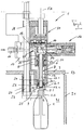
- 1 is a filling element of a filling machine of rotating design for filling bottles 2 with a liquid product.
- the filling element 1 is provided together with a plurality of further filling elements on the circumference of a rotatable about the vertical axis of the machine rotor 3 and forms together with a bottle carrier 4 each one of the filling positions on the rotor third
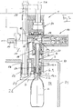
- the filling element 1 is u.a. suitable for a free-jet filling, in which the respective bottle 2 with its mouth of the bottle 2.1 is spaced from the filling element 1 and the liquid contents of the respective bottle during the filling process in a free stream 5 flows, so that displaced from the contents of the bottle air and / or Gas volume in the area of the bottle mouth 2.1 can freely enter the environment.
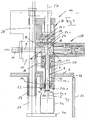
- the filling element 1 is also suitable for filling the bottles 2 under counter pressure (pressure filling), the bottles 2 then during the filling process according to the FIG. 3 abut with their bottle mouth 2.1 in sealing position against the respective filling element 1.
- the filling element 1 consists of a housing 6 in which u. a. a branching flow path is formed, which is formed by the two flow paths 7 and 8. This is associated with a common connection channel 9, via which the liquid filling material is supplied during filling of an outer connection 10.
- the connection channel 9 at the same time forms the measuring section of a measuring device 11 (MID sensor), with which the amount of filling material flowing in the respective bottle 2 during filling, for volume control of the filling process is detected.
- the flow path 7 is partially formed by the open at both ends ram channel 12.1 a tubular with its axis Medfeldse FA defining plunger 12, which merges on the housing bottom 6.1 in a pipe section 13, in which a gas barrier is arranged 13.1 and which for the free jet filling a short filling tube forms.
- the gas barrier 13.1 is in the simplest case, a sieve-like insert with a plurality of openings or an insert having a plurality of channels has, which are each open to the plunger channel 12.1 as well as to which the discharge opening for the liquid filling material forming the lower end of the pipe section 13. With the upper end of the plunger channel 12.1 opened into a valve chamber.
- the liquid valve 15 consists of a valve body 17 controlled by an actuator 16, which is movable in the illustrated embodiment to open and close the liquid valve 15 by a valve in a direction perpendicular to the Greetachse FA and thus oriented radially to the machine axis axis direction and with a corresponding valve surface 18th interacts.
- the plunger 12 is guided in the direction of the Greelementachse FA by a predetermined stroke axially displaceable in the housing 6 and in a formed in this housing circular cylindrical housing portion 19, using disc-shaped diaphragm seals 20 and radial seals 21, the 19 in the housing section Gap between the outer surface of the plunger 12 and the surrounding this plunger cylinder inner surface of the housing portion 19 seal.
- the plunger 12 biased spring-loaded in the lower position of its stroke movement.
- the flow path 8 is similar to the usual filling elements in liquid channel formed and opens at the bottom 6.1 of the housing 6 in a tubular piece 13 enclosing annular discharge opening 22 to which a second liquid valve 23 is provided, which is closed when the plunger 12 is lowered.
- the lower end of the plunger 12 is formed as a valve body 24, which cooperates with a formed in the flow path 8 in the vicinity of the discharge opening 22 valve surface.
- valve chamber 14 In the illustrated embodiment, two controlled gas channels 26 and 27, in each of which a controllable valve 26. 1 or 27. 1 is provided, open into the valve chamber 14.
- the container carrier 4 is in the embodiment of Figures 1 - 3 designed so that held him the respective bottle 2 with a mouth flange 2.2 hanging is.
- this is held on a rod 28 oriented with its axis parallel to the filling element axis FA, which is guided axially displaceably on the housing 6 and on the rotor 3 for a movement stroke.
- the rod 28 and thus also the respective container carrier 4 are biased by a compression spring 29 in the lower, lowered stroke position.
- the rod 28 actuator 30 in the form of, for example, a pneumatic piston-cylinder arrangement, the rod 28 and the container carrier 4 can be raised from the lower stroke position.
- the lower stroke position of the rod 28 and thus the lower layer of the container carrier 4 corresponds to the position during the free-jet filling.
- the rod 28 and the respective container carrier 4 are moved to an upper stroke position.
- the gas barrier 13.1 having pipe section 13 projects beyond the plane of the annular seal 25.1 and thus also via the discharge opening 22 downwards, wherein the lower end of the gas barrier 13 is approximately level with the lower edge of the centering element 24.
- a wall which separates an interior space 32, in which the filling elements 1 rotate at their lower end and the container carriers 4, from the environment, for example for a cold aseptic filling.
- a seal 33 is provided at the transition between the rotor 3 and the fixed wall 31, a seal 33 is provided.
- each bottle 2 is transferred to a container inlet of the filling machine in each case to one of a filling element 1 and an associated container carrier 4 filling position, in such a way that each bottle 2 with its axis axis coaxially or approximately coaxially aligned with the Greelementachse FA oriented with the mouth flange 2.2 hanging is held on the container carrier 4, with the bottle mouth 2.1 spaced from the filling element 1 and from the lower end of the gas barrier 13.1 having tubular piece 13.
- the filling process is initiated, ie the liquid product then passes through the outer terminal 10, the connection channel 9, the valve chamber 14, the plunger channel 12.1 and the gas barrier 13.1 having pipe section 13 as a free jet 5 in the interior of the
- the individual channel 8 and the annular discharge opening 22 are closed by the liquid valve 23.
- About the measuring device 11 of the respective bottle 2 is fed during the filling process amount of filling. If the required volume of filling material is reached, the liquid valve 15 is closed due to the signal supplied by the measuring device 11 and thus the filling process is terminated.
- the filled bottles 2 are removed at a container outlet from the respective container carrier 4 and a machine for closing (Capper) fed.
- one of the two gas channels 26 or 27 can be opened by actuating the corresponding control or gas valve 26.1 or 27.1 to the environment or to a special, designed for example in the rotor gas channel.
- FIG. 3 shows the working mode of the respective filling element 1 during the pressure filling.
- the respective bottle 2 is brought by lifting with the container carrier 4 with its bottle mouth 2.1 in sealing position against the filling element 1 and the seal 25.1.
- the liquid valve 15 is closed in this working mode.
- the interior 2 of the sealing layer provided on the filling element 1 bottle 2 is biased, for example via the valve chamber 14 and the plunger channel 12.1, that is acted upon by a pressurized inert gas.
- the filling material passes through the outer port 10, the connection channel 9 with the filling pressure in the flow path 8, so that due to this inter alia, the lower, annular membrane seal 20 acting pressure of the plunger 12 is moved to its upper stroke position and the liquid valve 23 opens, so that the liquid contents then flows through the annular discharge opening 22 along the bottle inner surface in the respective bottle 2.
- the return gas displaced from the bottle 2 through the liquid filling material flows through the gas barrier 13.1, the plunger channel 12.1 serving as return gas channel in this operating mode and the valve chamber 14 into at least one open gas channel 26 or 27. Controlled by the signal from the measuring device 11 is reached when it reaches of the desired filling volume of the filling process by shooting the gas channels 26 and 27 and the liquid valve 23 is completed.
- the FIG. 4 shows a filling element 1a for optional free-jet filling or pressure filling of cans 2a.
- the filling element 1a differs from the filling element 1 essentially only by the slightly larger than the seal 25.1 seal 25a.1. Shown in the FIG. 4 the working state of the filling element 1a during free jet filling with the liquid valve 15 open. The pressure filling takes place at the container or can rim 2a.1 pressed against the seal 25a.1 in a sealing position with the container carrier 4a raised.
- FIG. 5 the filling element 1 during the so-called CIP cleaning.
- the centering element 24 is closed by a plate-shaped closure element 34, so that with open liquid valves 15 and 23, all the channels in the interior the raised container carrier 4a against the seal 25a.1in pressed sealing position container or, can edge 2a.1.
- FIG. 5 the filling element 1 during the so-called CIP cleaning.
- the centering element 24 is closed by a plate-shaped Versichlusselement 34, so that with open liquid valves 15 and 23, all the channels in the interior of the respective filling element 1 can be traversed by the cleaning medium used in the CIP cleaning. How the particular FIG.
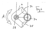
- the plate-like VerInstitutelennent 34 is provided on the container carrier 4 and can be brought by pivoting the circular sector shaped container carrier 4 about the axis of the rod 28 (double arrow A) in a position below the centering element 25, so then by activating the actuating element 30, the closure element 34 is brought into abutment against the centering element 25, thereby forming together with the centering element 25 on the housing bottom 6.1 a rinsing cap, which connects the opened dispensing opening 22 with the gas barrier 13.1 existing blank 13.
- a recess 35 or 36 is respectively provided on the circular sector-shaped container support 4 laterally of the closure element 34, with a different size, so that the container support 4 is adjusted by pivoting the rod 28 on bottles 2 with different diameters in the region of the mouth flange 2.2 can be.
Abstract
Description
Die Erfindung bezieht sich auf ein Füllelement gemäß Oberbegriff Patentanspruch 1 sowie auf eine Füllmaschine gemäß Oberbegriff Patentanspruch 21.The invention relates to a filling element according to the preamble of
Füllelemente zur Verwendung bei Füllmaschinen, insbesondere auch bei solchen umlaufender Bauart, zum Füllen von Flaschen oder der dergleichen Behälter mit einem flüssigen Füllgut sind In unterschiedlichen Ausführungen bekannt. Bekannt sind dabei u.a. Füllelemente für eine so genannte Freistrahlfüllung, bei der das flüssige Füllgut dem jeweiligen, vom Füllelement beabstandeten Behälter während der Füllphase von der Abgabeöffnung des Füllelementes als freler Strahl zufließt. Bekannt sind u.a. auch Füllelemente für die so genannte Druckfüllung oder Gegendruckfüllung, bei der das flüssige Füllgut dem jeweiligen, in Dichtlage mit dem Füllelement befindlichen Behälter während der Füllphase unter Druck (Fülldruck) zufließt.Filling elements for use in filling machines, especially in such peripheral design, for filling bottles or the like containers with a liquid product are known in different designs. U.a. Filling elements for a so-called free-jet filling in which the liquid product flows to the respective, spaced from the filling container during the filling phase of the discharge opening of the filling element as a free jet. Known are u.a. Also filling elements for the so-called pressure filling or counter-pressure filling, in which the liquid product flows to the respective, in sealing position with the filling element container during the filling phase under pressure (filling pressure).
Bei der Frelstrahlfüllung besteht grundsätzlich das Problem eines Nachtropfens der Füllelemente jeweils nach Beendigung der Füllphase und nach dem Abnehmen des gefüllten Behälters vom Behälterträger. Dieses Nachtropfen kann durch die Verwendung einer Gassperre an der Abgabeöffnung verhindert werden.When the Frelstrahlfüllung basically there is the problem of a dripping of the filling elements after completion of the filling phase and after removing the filled container from the container carrier. This dripping can be prevented by the use of a gas barrier at the discharge opening.
Allerdings ist ein Füllelement mit einer, an seiner Abgabeöffnung angeordneten Gassperre für eine Druckfüllung insbesondere eines kohlensäurehaltigen Füllgutes nicht geeignet.However, a filling element with a, arranged at its discharge opening gas barrier for a pressure filling in particular a carbonated filling material is not suitable.
Bei bzw. nach dem Schließen des Füllventils wird eine bestimmte Menge des flüssigen Füllguts im Strömungsweg oberhalb der Gassperre an dieser anstehend zurückgehalten. Bei der, bei Druckfüllung an das Schließen des Füllventils anschließenden Druck- und/oder Restentlastung kommt es dann bei dem oberhalb der Gassperre anstehendem, kohlesäurehaltigen Füllgut zu einem Freisetzen der enthaltenen Kohlensäure. Hierdurch wird das Füllgut durch die Gassperre gedrückt, und zwar mit der Folge einer erheblichen Verschmutzung der Füllmaschine, was insbesondere auch bei einer kaltaseptischen Abfüllung wegen der hohen Anforderungen an die Sterilität nicht tolerierbar ist.During or after the closing of the filling valve, a certain amount of the liquid filling material is retained in the flow path above the gas barrier at this pending. When, in pressure filling at the closing of the filling valve subsequent pressure and / or residual relief then it comes in the pending above the gas barrier, carbonated contents to release the carbon dioxide contained. As a result, the filling material is pressed through the gas barrier, with the result of a significant contamination of the filling machine, which is not tolerable especially in a cold aseptic filling because of the high demands on sterility.
Aus der
Sollen bekannte Füllelemente sowohl für eine Freistrahlfüllung, als auch für eine Druckfüllung genutzt werden, ist es daher notwendig, die bei der Freistrahlfüllung zur Vermeidung eines Nachtropfens vorgesehenen Gassperren vor der Druckfüllung zu entfernen bzw. umgekehrt nach der Druckfüllung und vor Freistrahlfüllung wieder zu montieren, was eine zeit- und arbeitsaufwendige Umstellung der jeweiligen Füllmaschine bedeutet und zusätzliche Produktionskosten sowie zusätzliche Reinigungszyklen bedingt.If known filling elements are to be used both for a free-jet filling and for a pressure filling, it is therefore necessary to remove the gas barriers provided in the free-jet filling to avoid dripping before the pressure filling or vice versa to mount again after the pressure filling and free jet filling, which a time and labor consuming conversion of the respective filling machine means additional production costs and additional cleaning cycles.
Aufgabe der Erfindung ist es, ein Füllelement aufzuzeigen, welches problemlos eine Umstellung zwischen einer Freistrahlfüllung und einer Druckfüllung ermöglicht. Zur Lösung dieser Aufgabe ist ein Füllelement entsprechend dem Patentanspruch 1 ausgebildet. Eine Füllmaschine ist Gegenstand des Patentanspruchs 21.The object of the invention is to show a filling element, which easily allows a change between a free jet filling and a pressure filling. To solve this problem, a filling element according to the
Das erfindungsgemäße Füllelement kann ohne eine Demontage bzw. erneute Montage der Gassperren wahlweise für die Freistrahlfüllung und die Druckfüllung verwendet werden. In beiden Fällen arbeitet das Füllelement tropffrei. Bei der Druckfüllung wird das flüssige Füllgut im Inneren des Füllelementes entlang eines Strömungsweges bzw. Flüssigkeitskanals geführt, in welchem die Gassperre nicht vorgesehen ist. Die Gassperre befindet sich in einem zusätzlichen Strömungsweg, der bei der Druckfüllung als Rückgaskanal genutzt wird. Das Rückgas wird hierbei durch die Gassperre geführt, was ohne Nachteile möglich ist. Die Umstellung von der Druckfüllung auf die Freistrahlfüllung erfolgt lediglich durch Sperren des für die Druckfüllung verwendeten Flüssigkeitsventils und durch Öffnen eines weiteren Flüssigkeitsventils, über welches dann das flüssige Füllgut in den zusätzlichen Strömungsweg gelangt, der die mit der Gassperre versehene Abgabeöffnung aufweist, sodass es über diesen Strömungsweg und die mit der Gassperre versehene Abgabeöffnung als freier Strahl dem zu füllenden Behälter zufließen kann.The filling element according to the invention can be used without disassembly or reassembly of the gas locks optionally for the jet filling and the pressure filling. In both cases, the filler works drip-free. During the pressure filling, the liquid filling material is guided in the interior of the filling element along a flow path or liquid channel in which the gas barrier is not provided. The gas barrier is located in an additional flow path, which is used in the pressure filling as a return gas channel. The return gas is guided through the gas barrier, which is possible without disadvantages. The changeover from the pressure filling to the free jet filling takes place merely by blocking the liquid valve used for the pressure filling and by opening a further liquid valve, via which the liquid filling material then passes into the additional flow path which has the gas opening provided with the discharge opening, so that it over this Flow path and provided with the gas barrier discharge opening can flow as a free jet to the container to be filled.
Die Umstellung zwischen den beiden Füllverfahren (Freistrahlfüllen/Druckfüllen) kann somit ohne Umbauten am Füllelement nur durch Steuerung entsprechender Ventile erfolgen. Die Gassperre muss für die Umstellung nicht demontiert bzw. wieder montiert werden.The conversion between the two filling methods (free jet filling / pressure filling) can thus be done without modifications to the filling element only by controlling appropriate valves. The gas barrier does not have to be dismantled or reassembled for the conversion.
Das erfindungsgemäße Füllelement eignet sich für die Freistrahlfüllung und Druckfüllung von Flaschen oder anderen Behältern, insbesondere auch für die Freistrahlfüllung und Druckfüllung von Dosen. Weiterbildungen der Erfindung sind Gegenstand der Unteransprüche. Die Erfindung wird im Folgenden anhand der Figuren an einem Ausführungsbeispiel näher erläutert. Es zeigen:
- Fig. 1
- in vereinfachter Darstellung und im Schnitt ein Füllelement einer Füllmaschine umlaufender Bauart, zusammen mit einem diesem Füllelement zugeordneten Behälter- oder Flaschenträger;
- Fig. 2
- das Füllelement der
Figur 1 - Fig. 3
- das Füllelement der
Figur 1 - Fig. 4
- das Füllelement der
Figur 1 - Fig. 5
- das Füllelement der
Figur 1 - Fig. 6
- in vereinfachter Darstellung eine Draufsicht auf den Behälter- oder Flaschenträger des Füllelementes der
Figur 1
- Fig. 1
- in a simplified representation and in section, a filling element of a filling machine of rotating design, together with this filling element associated container or bottle carrier;
- Fig. 2
- the filling element of
FIG. 1 , together with a bottle to be filled in a free-jet filling; - Fig. 3
- the filling element of
FIG. 1 together with a bottle to be filled at a pressure or counter-pressure filling; - Fig. 4
- the filling element of
FIG. 1 , together with a can to be filled (eg beverage can) with a free-jet filling; - Fig. 5
- the filling element of
FIG. 1 in a CIP cleaning; - Fig. 6
- in a simplified representation of a plan view of the container or bottle carrier of the filling element of
FIG. 1 ,
In den Figuren ist 1 ein Füllelement einer Füllmaschine umlaufender Bauart zum Füllen von Flaschen 2 mit einem flüssigen Füllgut. Das Füllelement 1 ist zusammen mit einer Vielzahl weiterer Füllelemente am Umfang eines um die vertikale Maschinenachse umlaufend antreibbaren Rotors 3 vorgesehen und bildet zusammen mit einem Flaschenträger 4 jeweils eine der Füllpositionen an dem Rotor 3.In the figures, 1 is a filling element of a filling machine of rotating design for filling
Das Füllelementes 1 ist u.a. für eine Freistrahlfüllung geeignet, bei der die jeweilige Flasche 2 mit ihrer Flaschenmündung 2.1 vom Füllelement 1 beabstandet ist und das flüssige Füllgut der jeweiligen Flasche während des Füllprozesses in einem freien Strahl 5 zufließt, sodass das vom Füllgut aus der Flasche verdrängte Luft- und/oder Gasvolumen im Bereich der Flaschenmündung 2.1 frei in die Umgebung gelangen kann.The
Weiterhin eignet sich das Füllelement 1 auch zum Füllen der Flaschen 2 unter Gegendruck (Druckfüllen), wobei die Flaschen 2 dann während des Füllprozesses entsprechend der
Im Einzelnen besteht das Füllelement 1 aus einem Gehäuse 6, in welchem u. a. ein sich verzweigender Strömungspfad ausgebildet ist, der von den beiden Strömungswegen 7 und 8 gebildet ist. Diesen ist ein gemeinsamer Anschlusskanal 9 zugeordnet, über den das flüssige Füllgut beim Füllen von einer äußeren Verbindung 10 zugeführt wird. Der Anschlusskanal 9 bildet zugleich die Messstrecke einer Messeinrichtung 11 (MID-Sensor), mit der die der jeweiligen Flasche 2 beim Füllen, zufließende Menge an Füllgut zur Volumensteuerung des Füllprozesses erfasst wird.In detail, the
Der Strömungsweg 7 ist teilweise von dem beidendig offenen Stößelkanal 12.1 eines rohrartigen mit seiner Achse die Füllelementachse FA definierenden Stößels 12 gebildet, der an der Gehäuseunterseite 6.1 in ein Rohrstück 13 übergeht, in welchem eine Gassperre 13.1 angeordnet ist und welches für die Freistrahlfüllung ein kurzes Füllrohr bildet. Die Gassperre 13.1 ist im einfachsten Fall ein siebartiger Einsatz mit einer Vielzahl von Öffnungen oder aber ein Einsatz, der eine Vielzahl von Kanälen aufweist, die jeweils zu dem Stößelkanal 12.1 sowie auch an dem die Abgabeöffnung für das flüssige Füllgut bildenden unteren Ende des Rohrstückes 13 offen sind. Mit dem oberen Ende mündete der Stößelkanal 12.1 in eine Ventilkammer. 14 eines Flüssigkeitsventils 15, über welches die Ventilkammer 14 und damit auch der Stößelkanal 12.1 gesteuert mit dem Verzweigungspunkt der beiden Strömungswege 7 und 8 bzw. mit dem Anschlusskanal 9 verbunden werden kann. Das Flüssigkeitsventil 15 besteht aus einem von einer Betätigungseinrichtung 16 angesteuerten Ventilkörper 17, der bei der dargestellten Ausführungsform zum Öffnen und Schließen des Flüssigkeitsventils 15 um einen Ventilhub in einer senkrecht zur Füllelementachse FA und damit radial zur Maschinenachse orientierten Achsrichtung bewegbar ist und mit einer entsprechenden Ventilfläche 18 zusammenwirkt.The
Der Stößel 12 ist in Richtung der Füllelementachse FA um einen vorgegebenen Hub axial verschiebbar im Gehäuse 6 bzw. in einem in diesem Gehäuse ausgebildeten kreiszylinderförmigen Gehäuseabschnitt 19 geführt, und zwar unter Verwendung von scheibenförmigen Membrandichtungen 20 und Radialdichtungen 21, die im Bereich des Gehäuseabschnittes 19 den Spalt zwischen der Außenfläche des Stößels 12 und der diesen Stößel umgebenden Zylinderinnenfläche des Gehäuseabschnitts 19 abdichten. Der Stößel 12 in die untere Stellung seiner Hubbewegung gefedert vorgespannt.The
Der Strömungsweg 8 ist ähnlich dem bei Füllelementen üblichen Flüssigkeitskanal ausgebildet und mündet an der Unterseite 6.1 des Gehäuses 6 in eine das Rohrstück 13 umschließende ringförmige Abgabeöffnung 22, an der ein zweites Flüssigkeitsventil 23 vorgesehen ist, welches bei abgesenktem Stößel 12 geschlossen ist. Für das Flüssigkeitsventil 23 ist das untere Ende des Stößels 12 als Ventilkörper 24 ausgebildet, der mit einer im Strömungsweg 8 in der Nähe der Abgabeöffnung 22 ausgebildeten Ventilfläche zusammenwirkt.The
An der Gehäuseunterseite 1.1 ist weiterhin ein über diese Unterseite wegstehendes ringförmiges Zentrierelement 25 vorgehen, in dem auch eine die Abgabeöffnung 22 umschließende ringförmige Dichtung 25.1 vorgesehen ist, gegen die die jeweilige Flasche 2 beim Druckfüllen mit ihrer Mündung 2.1 abgedichtet anliegt.On the underside of the housing 1.1 a wegstehendes on this underside annular centering
In die Ventilkammer 14 münden bei der dargestellten Ausführungsform zwei gesteuerte Gaskanäle 26 und 27, in denen jeweils ein steuerbares Ventil 26.1 bzw. 27.1 vorgesehen ist.In the illustrated embodiment, two controlled
Der Behälterträger 4 ist bei der Ausführungsform der
Wie die Figuren weiterhin zeigen, steht das die Gassperre 13.1 aufweisende Rohrstück 13 über die Ebene der ringförmigen Dichtung 25.1 und damit auch über die Abgabeöffnung 22 nach unten vor, wobei das untere Ende der Gassperre 13 etwa niveaugleich mit dem unteren Rand des Zentrierelementes 24 liegt.As the figures further show, the gas barrier 13.1 having
Mit 31 ist eine Wandung bezeichnet, die einen Innenraum 32, in dem die Füllelemente 1 mit ihrem unteren Ende sowie die Behälterträger 4 umlaufen, von der Umgebung trennt, beispielsweise für eine kaltaseptische Abfüllung. Am Übergang zwischen dem Rotor 3 und der feststehenden Wand 31 ist eine Dichtung 33 vorgesehen.31 denotes a wall which separates an
Für das Freistrahlfüllen entsprechend der
Zum Entleeren der Ventilkammer 14 und des Stößelkanals 12.1 kann einer der beiden Gaskanäle 26 oder 27 durch Betätigen des entsprechenden Steuer- oder Gasventils 26.1 bzw. 27.1 zur Umgebung oder zu einem speziellen, beispielsweise im Rotor ausgebildeten Gaskanal geöffnet werden.To empty the
Die
Die
Die
Die
Wie die
Die Erfindung wurde voranstehend an einem Ausführungsbeispiel beschrieben, weiter Ausführungsbeisplele sind in den abhängigen Ansprüchen ausgeführt.The invention has been described above by means of an embodiment, further embodiments are set forth in the dependent claims.
- 1, 1a1, 1a
- Füllelementfiller
- 22
- Flaschebottle
- 2.12.1
- Flaschenmündungbottle mouth
- 2.22.2
- MündungsflanschMündungsflansch
- 2a2a
- Dosecan
- 2a.12a.1
- Dosenrandcan edge
- 33
- Rotorrotor
- 4, 4a4, 4a
- Behälterträgercontainer carrier
- 55
- FüllgutstrahlFüllgutstrahl
- 66
- Gehäusecasing
- 6.16.1
- GehäuseunterseiteHousing bottom
- 7, 87, 8
- Strömungswegflow
- 99
- Anschlusskanalconnecting channel
- 1010
- äußerer Anschlussouter connection
- 1111
- Messeinrichtungmeasuring device
- 1212
- Stößeltappet
- 12.112.1
- Stößelkanalram channel
- 1313
- Rohrstückpipe section
- 13.113.1
- Gassperregas barrier
- 1414
- Ventilkammervalve chamber
- 1515
- Flüssigkeitsventilliquid valve
- 1616
- Betätigungselementactuator
- 1717
- Ventilkörpervalve body
- 1818
- Ventilsitzvalve seat
- 1919
- Gehäuseabschnitthousing section
- 2020
- ringförmige Membrandichtungannular membrane seal
- 2121
- Radialdichtungradial seal
- 2222
- ringförmige Abgabeöffnungannular discharge opening
- 2323
- Flüssigkeitsventilliquid valve
- 2424
- Ventilkörpervalve body
- 2525
- Zentrierelementcentering
- 25.125.1
-
Dichtung im Zentrierelement 25Seal in the centering
element 25 - 25a.125a.1
- Dichtungpoetry
- 26, 2726, 27
- Gaskanalgas channel
- 26.1, 27.126.1, 27.1
- Steuerventilcontrol valve
- 2828
- Stangepole
- 2929
- Federfeather
- 3030
- Betätigungselementactuator
- 3131
- Wandwall
- 3232
- Raumroom
- 3333
- Dichtungpoetry
- 3434
- Verschlusselementclosure element
- 35, 3635, 36
- Ausnehmungrecess
- AA
-
Verstellung des Behälterträgers 4Adjustment of the
container carrier 4 - FAFA
- vertikale Füllelementachsevertical filler axis
Claims (22)
- Filling element for a filling machine for filling bottles or similar containers (2, 2a) with a bulk liquid, with a liquid channel (8) inside an enclosure (6) of the filling element (1) and with a controllable first liquid valve (23) placed in the liquid channel (8) between a connection (9) for supplying the bulk liquid and at least one first discharge orifice (22) for discharging the bulk liquid into the container (2, 2a) to be filled, characterised in
that, in the enclosure (6) of the filling element (1, 1a), in addition to the liquid channel (8), a further flow channel (7) is formed which, controlled by means of an additional liquid valve (15), can be connected with the connection (9) for supplying the bulk liquid, and
that the further flow channel (7), in the area of the first discharge orifice (22), forms at least one further discharge orifice in which a gas lock (13.1) is provided. - Filling element according to claim 1, characterised in that the at least one further discharge orifice is formed by a short filling tube (13).
- Filling element according to claim 1 or 2, characterised in that the at least one first discharge orifice (22) has an annular or partially annular shape.
- Filling element according to claim 2, characterised in that the at least one first discharge orifice (22) encloses the at least one further discharge orifice in an at least partially annular manner.
- Filling element according to any one of the preceding claims, characterised in that the gas lock (13.1) has a sieve-like shape and/or is formed by a plurality of channels that are each open at both ends.
- Filling element according to any one of the preceding claims, characterised in that the first liquid valve (23) has a valve body (24) formed or provided at a valve tappet (12), said valve body being movable, for opening and closing this liquid valve, by a valve stroke in an axial direction, for example in a vertical filling element axis (FA), and that a tappet channel (12.1) is formed in the valve tappet (12), said tappet channel forming at least a part of the further flow path (7).
- Filling element according to any one of the preceding claims, characterised in that at least one controllable gas channel (26, 27) leads into the further flow path (7).
- Filling element according to any one of the preceding claims, characterised in that the further liquid valve (15) has a valve body (17) which, for opening and closing the liquid valve, is movable by a valve stroke through an actuating element (16).
- Filling element according to claim 8, characterised in that the valve body (17) of the further liquid valve (15) is movable in an axial direction transversal or vertical to the filling element axis (FA).
- Filling element according to any one of the preceding claims, characterised in that the further liquid valve (15) has a valve body (17) which, for opening and closing this liquid valve, is movable by a valve stroke in a valve chamber (14).
- Filling element according to claim 10, characterised in that the valve chamber (14) is part of the additional flow path (7).
- Filling element according to claims 6 and 10, characterised in that the tappet channel (12.1) leads into the valve chamber (14).
- Filling element according to claims 7 and 10, characterised in that the at least one controllable gas channel (26, 27) leads into the valve chamber (14).
- Filling element according to any one of the preceding claims, characterised in that, for freeflow filling, it can be controlled such that the bulk liquid flows as a free jet (5), when the first liquid valve (23) is closed and the additional liquid valve (15) is open, to the respective container (2, 2a) arranged under the filling element (1, 1a) via the further flow path (7) and the further discharge orifice equipped with the gas lock (13.1).
- Filling element according to any one of the preceding claims, characterised in that the filling element (1, 1 a) is controllable for pressure filling such that the bulk liquid, with the further liquid valve (15) locked and the first liquid valve (23) open, flows to the container (2, 2a) contacting, in the sealed position, the filling element (1, 1a) via the at least one first discharge orifice (23) and the further flow path (7) serves as a return gas channel.
- Filling element according to any one of the preceding claims, characterised by a container carrier (4, 4a) at the filling element (1, 1a) and by an actuating device (30) for raising and lowering the container carrier (4, 4a).
- Filling element according to claim 16, characterised in that the container carrier (4) is designed for a suspended arrangement of the respective container (2).
- Filling element according to claim 15, characterised in that the container carrier (4a) is designed for a standing arrangement of the respective container (2a).
- Filling element according to any one of the preceding claims, characterised by a centering element (25) which encloses the at least one first discharge orifice (22), said centering element being closable for CIP cleaning by a closing element (34), in order to form a rinsing space into which lead the at least one first discharge orifice (22) and also the at least one further discharge orifice having the gas lock (13.1).
- Filling element according to claim 19, characterised in that the closing element (34) is provided or formed at the container carrier (4).
- Filling machine for filling containers (2, 2a) with a bulk liquid, with at least one filling station formed by a filling element (1,1 a) and a container carrier (4, 4a), characterised in that the filling element (1, 1a) is designed according to one of the preceding claims.
- Filling machine according to claim 21, characterised by several filling elements (1, 1 a) on a rotor (3) that can be rotatably driven about a vertical machine axis.
Priority Applications (2)
| Application Number | Priority Date | Filing Date | Title |
|---|---|---|---|
| SI200731023T SI2010447T1 (en) | 2006-04-15 | 2007-04-03 | Filling element and filling machine with a filling element |
| PL07723939T PL2010447T3 (en) | 2006-04-15 | 2007-04-03 | Filling element and filling machine with a filling element |
Applications Claiming Priority (2)
| Application Number | Priority Date | Filing Date | Title |
|---|---|---|---|
| DE102006017706A DE102006017706A1 (en) | 2006-04-15 | 2006-04-15 | Filling elements and filling machine with a filling element |
| PCT/EP2007/002998 WO2007118607A1 (en) | 2006-04-15 | 2007-04-03 | Filling element and filling machine with a filling element |
Publications (2)
| Publication Number | Publication Date |
|---|---|
| EP2010447A1 EP2010447A1 (en) | 2009-01-07 |
| EP2010447B1 true EP2010447B1 (en) | 2012-07-18 |
Family
ID=38324053
Family Applications (1)
| Application Number | Title | Priority Date | Filing Date |
|---|---|---|---|
| EP07723939A Active EP2010447B1 (en) | 2006-04-15 | 2007-04-03 | Filling element and filling machine with a filling element |
Country Status (9)
| Country | Link |
|---|---|
| US (2) | US20090095370A1 (en) |
| EP (1) | EP2010447B1 (en) |
| JP (1) | JP5037602B2 (en) |
| CN (1) | CN101437747B (en) |
| DE (1) | DE102006017706A1 (en) |
| PL (1) | PL2010447T3 (en) |
| RU (1) | RU2392220C1 (en) |
| SI (1) | SI2010447T1 (en) |
| WO (1) | WO2007118607A1 (en) |
Families Citing this family (42)
| Publication number | Priority date | Publication date | Assignee | Title |
|---|---|---|---|---|
| DE102007022259A1 (en) * | 2007-05-09 | 2009-01-15 | Khs Ag | Filling system and method for controlling a filling system |
| DE102007024102A1 (en) * | 2007-05-22 | 2008-11-27 | Khs Ag | treatment machine |
| FR2925886A1 (en) * | 2007-12-28 | 2009-07-03 | Serac Group Soc Par Actions Si | Container i.e. bottle, gripping device for product filling installation, has jaw mounted to be displaced between raised position in which another jaw is freely accessed and lowered position in which former jaw extends against latter jaw |
| DE102009005151B4 (en) * | 2009-01-15 | 2010-12-30 | Khs Gmbh | Container clip or clip |
| JP4737467B2 (en) * | 2009-02-27 | 2011-08-03 | 東洋製罐株式会社 | Aseptic filling of carbon dioxide containing liquid |
| FR2946623B1 (en) * | 2009-06-11 | 2016-07-01 | Serac Group | SUSPENDED DELIVERY DEVICE AND FILLING PLANT FOR CONTAINERS COMPRISING SUCH DEVICES. |
| RU2546479C2 (en) * | 2009-11-06 | 2015-04-10 | Тетра Лаваль Холдингз Энд Файнэнс С.А. | Filling machine with sealing valve |
| DE102009053350B4 (en) * | 2009-11-17 | 2011-09-22 | Khs Gmbh | filler |
| DE102010047883A1 (en) * | 2010-10-11 | 2012-04-12 | Khs Gmbh | Method and filling system for volume and / or quantity-controlled filling of containers |
| IT1403742B1 (en) * | 2011-01-20 | 2013-10-31 | G F S P A | TAKING UP A CONTAINER |
| KR101569603B1 (en) * | 2011-04-06 | 2015-11-16 | 미쯔비시 쥬우꼬오 쇼구힌호오소오기까이 가부시키가이샤 | Rotary-type filling machine and method for calculating filling quantity for rotary-type filling machine |
| DE102011016760A1 (en) * | 2011-04-12 | 2012-10-18 | Khs Gmbh | Method and filling machine for free jet filling of bottles or similar containers |
| DE102011111321A1 (en) | 2011-08-26 | 2013-02-28 | Khs Gmbh | filling |
| DE102011112925A1 (en) * | 2011-09-13 | 2013-03-14 | Khs Gmbh | Method, filling system and filling element for filling containers |
| DE102011121968A1 (en) * | 2011-12-21 | 2013-06-27 | Khs Gmbh | Filling element and filling system |
| DE102012009206A1 (en) * | 2012-05-10 | 2013-11-14 | Khs Gmbh | filling Machine |
| DE102012019161A1 (en) | 2012-09-28 | 2014-04-03 | Khs Gmbh | filling Machine |
| EP2958850B1 (en) | 2013-02-25 | 2018-06-20 | KHS GmbH | Filling system |
| DE102013101812A1 (en) * | 2013-02-25 | 2014-08-28 | Khs Gmbh | Filling system for filling bottles or containers with liquid filling material, has outer gas path which is formed with gas path valve, and is attached to steered inner gas path of two filling elements of filling location pair concerned |
| DE102013101813A1 (en) * | 2013-02-25 | 2014-08-28 | Khs Gmbh | Filling system for filling e.g. bottles with beverage, has gas path control valve comprising outer gas path and attached at respective non-controlled gas path of filling elements of respective pairs of filling locations |
| DE102013103309A1 (en) * | 2013-04-03 | 2014-10-09 | Khs Gmbh | Container treatment machine and method for feeding and / or removing containers to a container treatment machine |
| EP3003684B1 (en) * | 2013-05-30 | 2017-08-23 | Discma AG | Injection device comprising a central rod movable in a cleaning position |
| EP2821204B1 (en) * | 2013-07-02 | 2017-12-27 | Discma AG | Container-fabricating apparatus and a method for the cleaning thereof |
| ITMI20131163A1 (en) * | 2013-07-10 | 2015-01-11 | Smi Spa | FILLING DEVICE |
| EP2832681B1 (en) * | 2013-07-30 | 2016-11-16 | Sidel S.p.a. Con Socio Unico | Filling head and method |
| DE102013113070B3 (en) | 2013-11-26 | 2015-03-19 | Khs Gmbh | Filling element and filling machine |
| EP2889260B1 (en) * | 2013-12-30 | 2016-03-09 | Sidel S.p.a. Con Socio Unico | Unit for carrying out an operation on a container fillable with a pourable product |
| DE202014101722U1 (en) * | 2014-04-11 | 2015-04-14 | Krones Aktiengesellschaft | Container handling device for holding, gripping and / or rotating containers |
| NL2012833B1 (en) | 2014-05-16 | 2016-03-02 | Sluis Cigar Machinery Bv | Filling station for filling containers with a liquid. |
| DE102015116532A1 (en) | 2015-09-30 | 2017-03-30 | Khs Gmbh | Method and treatment station and treatment head for treating the interiors of KEGs and seal for use in such a treatment station |
| DE102016104286A1 (en) | 2016-03-09 | 2017-09-14 | Khs Gmbh | Outlet opening formed as an annular gap and purge = CO2 |
| DE102016114273A1 (en) | 2016-08-02 | 2018-02-08 | Khs Gmbh | Treatment device for a treatment of containers and actuator assembly for generating a rotary lifting movement in an aseptic clean room |
| KR102625187B1 (en) * | 2017-10-17 | 2024-01-16 | 더 코카콜라 컴파니 | Flexible fast filling line for personalized beverage package mixtures |
| DE102018100353B4 (en) * | 2018-01-09 | 2020-08-06 | Khs Gmbh | Filling device |
| CN108895302A (en) * | 2018-08-13 | 2018-11-27 | 连云港利丰医用氧产品有限公司 | A kind of method of filling inhalator jar medical oxygen under lid |
| DE102018132635A1 (en) * | 2018-12-18 | 2020-06-18 | Krones Ag | Container holder for a free jet filler |
| CN109704260A (en) * | 2019-03-05 | 2019-05-03 | 郑淳予 | Leak-proof device is used in a kind of bottling of fruit juice |
| US11208310B2 (en) * | 2019-05-06 | 2021-12-28 | Fountain Master, Llc | Fluid filling systems and methods |
| CN110550592A (en) * | 2019-10-12 | 2019-12-10 | 广州达意隆包装机械股份有限公司 | False cup device and liquid filling machine |
| DE102020110140A1 (en) * | 2020-04-14 | 2021-10-14 | Krones Aktiengesellschaft | Filling element with conversion from free jet to sieve outlet |
| US11434125B2 (en) * | 2020-06-05 | 2022-09-06 | WhidBrew Technologies, Inc | Automated beverage pouring device with foam control |
| DE102020129102A1 (en) * | 2020-11-04 | 2022-05-05 | Krones Aktiengesellschaft | Filling element and device for filling a container with a filling product |
Family Cites Families (18)
| Publication number | Priority date | Publication date | Assignee | Title |
|---|---|---|---|---|
| US4410108A (en) * | 1980-02-11 | 1983-10-18 | Elmar Industries, Inc. | Pressure-actuated valve for use with positive displacement filling machine |
| DE3903768C2 (en) * | 1988-08-20 | 1995-07-20 | Khs Masch & Anlagenbau Ag | Method for filling containers, in particular bottles, with a liquid filling material which is preferably under ambient pressure, and filling machine for carrying out this method |
| US5193593A (en) * | 1990-08-13 | 1993-03-16 | Colgate-Palmolive Company | Package filling method and apparatus |
| DE4213737A1 (en) * | 1991-10-17 | 1993-04-22 | Seitz Enzinger Noll Masch | METHOD FOR FILLING BOTTLES OR THE LIKE CONTAINERS WITH A LIQUID FILLING MATERIAL AND DEVICE FOR CARRYING OUT THIS METHOD |
| WO1993018849A1 (en) * | 1992-03-17 | 1993-09-30 | Nordson Corporation | Two-component dispensing system |
| DE4213738A1 (en) * | 1992-04-25 | 1993-10-28 | Seitz Enzinger Noll Masch | Filling element for filling machines for filling bottles or similar containers |
| US5431198A (en) * | 1994-05-20 | 1995-07-11 | Autoprod, Inc. | Apparatus and method of operation for a product filler machine |
| JP3484766B2 (en) * | 1994-06-08 | 2004-01-06 | 澁谷工業株式会社 | Filling valve |
| DE19818762A1 (en) * | 1998-04-27 | 1999-10-28 | Khs Masch & Anlagenbau Ag | Filling system and filling element |
| DE19818761A1 (en) * | 1998-04-27 | 1999-10-28 | Khs Masch & Anlagenbau Ag | Single-chamber filling system |
| JP2001122394A (en) * | 1999-10-22 | 2001-05-08 | Hitachi Zosen Corp | Nozzle cleaning apparatus for rotary type liquid charging machine |
| FR2801579B1 (en) * | 1999-11-29 | 2002-01-18 | Serac Group | FILLING NOZZLE WITH ADJUSTABLE FLOW RATE BY A SINGLE ACTUATION DEVICE AND IMPLEMENTATION METHOD |
| FR2813071B1 (en) * | 2000-08-16 | 2002-10-25 | Sidel Sa | FILLING SPOUT WITH UMBRELLA JET AND FILLING MACHINE PROVIDED WITH SUCH A SPOUT |
| FR2821615B1 (en) * | 2001-03-02 | 2004-12-03 | Jean Pierre Solignac | DEVICE FOR THE DOSED DELIVERY OF PRECISION OF PASTY OR LIQUID OR POWDER PRODUCTS |
| DE102004013211A1 (en) * | 2004-03-17 | 2005-09-29 | Khs Maschinen- Und Anlagenbau Ag | Filling valve for filling liquids in containers |
| DE102004015167B3 (en) * | 2004-03-27 | 2005-11-03 | Khs Maschinen- Und Anlagenbau Ag | filler |
| DE102004017205A1 (en) * | 2004-04-10 | 2005-10-27 | Khs Maschinen- Und Anlagenbau Ag | Filling machine of rotating design |
| DE102004022096B3 (en) * | 2004-05-05 | 2006-01-05 | Khs Maschinen- Und Anlagenbau Ag | Filling valve, equipped with a gas barrier with swirl effect |
-
2006
- 2006-04-15 DE DE102006017706A patent/DE102006017706A1/en not_active Withdrawn
-
2007
- 2007-04-03 WO PCT/EP2007/002998 patent/WO2007118607A1/en active Application Filing
- 2007-04-03 EP EP07723939A patent/EP2010447B1/en active Active
- 2007-04-03 JP JP2009504613A patent/JP5037602B2/en not_active Expired - Fee Related
- 2007-04-03 PL PL07723939T patent/PL2010447T3/en unknown
- 2007-04-03 CN CN2007800135261A patent/CN101437747B/en not_active Expired - Fee Related
- 2007-04-03 RU RU2008145056/12A patent/RU2392220C1/en not_active IP Right Cessation
- 2007-04-03 SI SI200731023T patent/SI2010447T1/en unknown
-
2008
- 2008-10-14 US US12/250,855 patent/US20090095370A1/en not_active Abandoned
-
2012
- 2012-10-29 US US13/663,088 patent/US8505594B2/en active Active
Also Published As
| Publication number | Publication date |
|---|---|
| WO2007118607A1 (en) | 2007-10-25 |
| CN101437747B (en) | 2011-02-09 |
| EP2010447A1 (en) | 2009-01-07 |
| JP2009533281A (en) | 2009-09-17 |
| US8505594B2 (en) | 2013-08-13 |
| JP5037602B2 (en) | 2012-10-03 |
| DE102006017706A1 (en) | 2007-10-25 |
| SI2010447T1 (en) | 2012-11-30 |
| CN101437747A (en) | 2009-05-20 |
| PL2010447T3 (en) | 2012-12-31 |
| US20130105043A1 (en) | 2013-05-02 |
| RU2392220C1 (en) | 2010-06-20 |
| US20090095370A1 (en) | 2009-04-16 |
Similar Documents
| Publication | Publication Date | Title |
|---|---|---|
| EP2010447B1 (en) | Filling element and filling machine with a filling element | |
| EP1580160B1 (en) | Filling head for counter pressure filling and free jet filling | |
| EP2146922B1 (en) | Filling system and method for controlling a filling system | |
| EP2029469B1 (en) | Filling element and filling machine comprising corresponding filling elements | |
| EP2598429B1 (en) | Filling machine | |
| EP2788275B1 (en) | Filler element comprising a trinox tube | |
| EP2969894B1 (en) | Method and filling machine for filling cans or the like containers with liquid contents | |
| EP1692071A1 (en) | Filling element for a filling machine and filling machine provided with filling elements of this type | |
| EP2882678B1 (en) | Multiple filling element for a filling system or a filling machine and filling machine | |
| EP2788274B1 (en) | Filler element and filling system | |
| DE102011111483A1 (en) | Container handling machine | |
| EP2398731B1 (en) | Method for the pressurised filling of bottles or like containers, and filling system and filling machine for carrying out said method | |
| WO2014166617A1 (en) | Filling element, filling system and method for filling containers | |
| EP2915772B1 (en) | Device for filling a container with a filling product | |
| DE2123865A1 (en) | Filling element | |
| EP2534089B1 (en) | Filling system for filling containers in a pressurized manner | |
| DE102005031217B4 (en) | Filling element and filling machine of rotating design | |
| EP2958849B1 (en) | Filling system and machine | |
| DE202012007517U1 (en) | Multiple filling element for a filling system or a filling machine and filling machine | |
| DE2042990A1 (en) | Full element | |
| DE102012015962A1 (en) | Filling machine for filling containers with liquid product, has fillers that are intended to be mounted on underside of rotor for supplying liquid filling in ring boiler | |
| DE102013101812A1 (en) | Filling system for filling bottles or containers with liquid filling material, has outer gas path which is formed with gas path valve, and is attached to steered inner gas path of two filling elements of filling location pair concerned |
Legal Events
| Date | Code | Title | Description |
|---|---|---|---|
| PUAI | Public reference made under article 153(3) epc to a published international application that has entered the european phase |
Free format text: ORIGINAL CODE: 0009012 |
|
| 17P | Request for examination filed |
Effective date: 20081117 |
|
| AK | Designated contracting states |
Kind code of ref document: A1 Designated state(s): AT BE BG CH CY CZ DE DK EE ES FI FR GB GR HU IE IS IT LI LT LU LV MC MT NL PL PT RO SE SI SK TR |
|
| AX | Request for extension of the european patent |
Extension state: AL BA HR MK RS |
|
| RAP1 | Party data changed (applicant data changed or rights of an application transferred) |
Owner name: KHS GMBH |
|
| 17Q | First examination report despatched |
Effective date: 20110606 |
|
| RIC1 | Information provided on ipc code assigned before grant |
Ipc: B67C 3/26 20060101AFI20120308BHEP Ipc: B67C 3/00 20060101ALI20120308BHEP Ipc: B67C 3/24 20060101ALI20120308BHEP Ipc: B67C 3/20 20060101ALI20120308BHEP |
|
| GRAP | Despatch of communication of intention to grant a patent |
Free format text: ORIGINAL CODE: EPIDOSNIGR1 |
|
| DAX | Request for extension of the european patent (deleted) | ||
| GRAS | Grant fee paid |
Free format text: ORIGINAL CODE: EPIDOSNIGR3 |
|
| GRAA | (expected) grant |
Free format text: ORIGINAL CODE: 0009210 |
|
| AK | Designated contracting states |
Kind code of ref document: B1 Designated state(s): AT BE BG CH CY CZ DE DK EE ES FI FR GB GR HU IE IS IT LI LT LU LV MC MT NL PL PT RO SE SI SK TR |
|
| REG | Reference to a national code |
Ref country code: GB Ref legal event code: FG4D Free format text: NOT ENGLISH |
|
| REG | Reference to a national code |
Ref country code: CH Ref legal event code: EP |
|
| REG | Reference to a national code |
Ref country code: AT Ref legal event code: REF Ref document number: 566947 Country of ref document: AT Kind code of ref document: T Effective date: 20120815 Ref country code: IE Ref legal event code: FG4D Free format text: LANGUAGE OF EP DOCUMENT: GERMAN |
|
| REG | Reference to a national code |
Ref country code: DE Ref legal event code: R096 Ref document number: 502007010240 Country of ref document: DE Effective date: 20120913 |
|
| REG | Reference to a national code |
Ref country code: NL Ref legal event code: VDEP Effective date: 20120718 |
|
| REG | Reference to a national code |
Ref country code: LT Ref legal event code: MG4D Effective date: 20120711 |
|
| REG | Reference to a national code |
Ref country code: PL Ref legal event code: T3 |
|
| PG25 | Lapsed in a contracting state [announced via postgrant information from national office to epo] |
Ref country code: IS Free format text: LAPSE BECAUSE OF FAILURE TO SUBMIT A TRANSLATION OF THE DESCRIPTION OR TO PAY THE FEE WITHIN THE PRESCRIBED TIME-LIMIT Effective date: 20121118 Ref country code: LT Free format text: LAPSE BECAUSE OF FAILURE TO SUBMIT A TRANSLATION OF THE DESCRIPTION OR TO PAY THE FEE WITHIN THE PRESCRIBED TIME-LIMIT Effective date: 20120718 Ref country code: CY Free format text: LAPSE BECAUSE OF FAILURE TO SUBMIT A TRANSLATION OF THE DESCRIPTION OR TO PAY THE FEE WITHIN THE PRESCRIBED TIME-LIMIT Effective date: 20120718 Ref country code: FI Free format text: LAPSE BECAUSE OF FAILURE TO SUBMIT A TRANSLATION OF THE DESCRIPTION OR TO PAY THE FEE WITHIN THE PRESCRIBED TIME-LIMIT Effective date: 20120718 |
|
| PG25 | Lapsed in a contracting state [announced via postgrant information from national office to epo] |
Ref country code: LV Free format text: LAPSE BECAUSE OF FAILURE TO SUBMIT A TRANSLATION OF THE DESCRIPTION OR TO PAY THE FEE WITHIN THE PRESCRIBED TIME-LIMIT Effective date: 20120718 Ref country code: PT Free format text: LAPSE BECAUSE OF FAILURE TO SUBMIT A TRANSLATION OF THE DESCRIPTION OR TO PAY THE FEE WITHIN THE PRESCRIBED TIME-LIMIT Effective date: 20121119 Ref country code: GR Free format text: LAPSE BECAUSE OF FAILURE TO SUBMIT A TRANSLATION OF THE DESCRIPTION OR TO PAY THE FEE WITHIN THE PRESCRIBED TIME-LIMIT Effective date: 20121019 Ref country code: SE Free format text: LAPSE BECAUSE OF FAILURE TO SUBMIT A TRANSLATION OF THE DESCRIPTION OR TO PAY THE FEE WITHIN THE PRESCRIBED TIME-LIMIT Effective date: 20120718 |
|
| PG25 | Lapsed in a contracting state [announced via postgrant information from national office to epo] |
Ref country code: NL Free format text: LAPSE BECAUSE OF FAILURE TO SUBMIT A TRANSLATION OF THE DESCRIPTION OR TO PAY THE FEE WITHIN THE PRESCRIBED TIME-LIMIT Effective date: 20120718 |
|
| PG25 | Lapsed in a contracting state [announced via postgrant information from national office to epo] |
Ref country code: DK Free format text: LAPSE BECAUSE OF FAILURE TO SUBMIT A TRANSLATION OF THE DESCRIPTION OR TO PAY THE FEE WITHIN THE PRESCRIBED TIME-LIMIT Effective date: 20120718 Ref country code: CZ Free format text: LAPSE BECAUSE OF FAILURE TO SUBMIT A TRANSLATION OF THE DESCRIPTION OR TO PAY THE FEE WITHIN THE PRESCRIBED TIME-LIMIT Effective date: 20120718 Ref country code: EE Free format text: LAPSE BECAUSE OF FAILURE TO SUBMIT A TRANSLATION OF THE DESCRIPTION OR TO PAY THE FEE WITHIN THE PRESCRIBED TIME-LIMIT Effective date: 20120718 Ref country code: ES Free format text: LAPSE BECAUSE OF FAILURE TO SUBMIT A TRANSLATION OF THE DESCRIPTION OR TO PAY THE FEE WITHIN THE PRESCRIBED TIME-LIMIT Effective date: 20121029 Ref country code: RO Free format text: LAPSE BECAUSE OF FAILURE TO SUBMIT A TRANSLATION OF THE DESCRIPTION OR TO PAY THE FEE WITHIN THE PRESCRIBED TIME-LIMIT Effective date: 20120718 |
|
| PLBE | No opposition filed within time limit |
Free format text: ORIGINAL CODE: 0009261 |
|
| STAA | Information on the status of an ep patent application or granted ep patent |
Free format text: STATUS: NO OPPOSITION FILED WITHIN TIME LIMIT |
|
| PG25 | Lapsed in a contracting state [announced via postgrant information from national office to epo] |
Ref country code: SK Free format text: LAPSE BECAUSE OF FAILURE TO SUBMIT A TRANSLATION OF THE DESCRIPTION OR TO PAY THE FEE WITHIN THE PRESCRIBED TIME-LIMIT Effective date: 20120718 |
|
| 26N | No opposition filed |
Effective date: 20130419 |
|
| PG25 | Lapsed in a contracting state [announced via postgrant information from national office to epo] |
Ref country code: BG Free format text: LAPSE BECAUSE OF FAILURE TO SUBMIT A TRANSLATION OF THE DESCRIPTION OR TO PAY THE FEE WITHIN THE PRESCRIBED TIME-LIMIT Effective date: 20121018 |
|
| REG | Reference to a national code |
Ref country code: DE Ref legal event code: R097 Ref document number: 502007010240 Country of ref document: DE Effective date: 20130419 |
|
| BERE | Be: lapsed |
Owner name: KHS G.M.B.H. Effective date: 20130430 |
|
| PG25 | Lapsed in a contracting state [announced via postgrant information from national office to epo] |
Ref country code: MC Free format text: LAPSE BECAUSE OF FAILURE TO SUBMIT A TRANSLATION OF THE DESCRIPTION OR TO PAY THE FEE WITHIN THE PRESCRIBED TIME-LIMIT Effective date: 20120718 |
|
| REG | Reference to a national code |
Ref country code: CH Ref legal event code: PL |
|
| REG | Reference to a national code |
Ref country code: IE Ref legal event code: MM4A |
|
| PG25 | Lapsed in a contracting state [announced via postgrant information from national office to epo] |
Ref country code: BE Free format text: LAPSE BECAUSE OF NON-PAYMENT OF DUE FEES Effective date: 20130430 Ref country code: LI Free format text: LAPSE BECAUSE OF NON-PAYMENT OF DUE FEES Effective date: 20130430 Ref country code: CH Free format text: LAPSE BECAUSE OF NON-PAYMENT OF DUE FEES Effective date: 20130430 |
|
| PG25 | Lapsed in a contracting state [announced via postgrant information from national office to epo] |
Ref country code: IE Free format text: LAPSE BECAUSE OF NON-PAYMENT OF DUE FEES Effective date: 20130403 |
|
| PG25 | Lapsed in a contracting state [announced via postgrant information from national office to epo] |
Ref country code: MT Free format text: LAPSE BECAUSE OF FAILURE TO SUBMIT A TRANSLATION OF THE DESCRIPTION OR TO PAY THE FEE WITHIN THE PRESCRIBED TIME-LIMIT Effective date: 20120718 |
|
| PG25 | Lapsed in a contracting state [announced via postgrant information from national office to epo] |
Ref country code: TR Free format text: LAPSE BECAUSE OF FAILURE TO SUBMIT A TRANSLATION OF THE DESCRIPTION OR TO PAY THE FEE WITHIN THE PRESCRIBED TIME-LIMIT Effective date: 20120718 |
|
| PG25 | Lapsed in a contracting state [announced via postgrant information from national office to epo] |
Ref country code: LU Free format text: LAPSE BECAUSE OF NON-PAYMENT OF DUE FEES Effective date: 20130403 Ref country code: HU Free format text: LAPSE BECAUSE OF FAILURE TO SUBMIT A TRANSLATION OF THE DESCRIPTION OR TO PAY THE FEE WITHIN THE PRESCRIBED TIME-LIMIT; INVALID AB INITIO Effective date: 20070403 |
|
| REG | Reference to a national code |
Ref country code: FR Ref legal event code: PLFP Year of fee payment: 10 |
|
| REG | Reference to a national code |
Ref country code: FR Ref legal event code: PLFP Year of fee payment: 11 |
|
| REG | Reference to a national code |
Ref country code: FR Ref legal event code: PLFP Year of fee payment: 12 |
|
| PGFP | Annual fee paid to national office [announced via postgrant information from national office to epo] |
Ref country code: PL Payment date: 20180322 Year of fee payment: 12 |
|
| PGFP | Annual fee paid to national office [announced via postgrant information from national office to epo] |
Ref country code: TR Payment date: 20180508 Year of fee payment: 12 |
|
| PGFP | Annual fee paid to national office [announced via postgrant information from national office to epo] |
Ref country code: GB Payment date: 20180418 Year of fee payment: 12 |
|
| REG | Reference to a national code |
Ref country code: AT Ref legal event code: MM01 Ref document number: 566947 Country of ref document: AT Kind code of ref document: T Effective date: 20190403 |
|
| GBPC | Gb: european patent ceased through non-payment of renewal fee |
Effective date: 20190403 |
|
| PG25 | Lapsed in a contracting state [announced via postgrant information from national office to epo] |
Ref country code: GB Free format text: LAPSE BECAUSE OF NON-PAYMENT OF DUE FEES Effective date: 20190403 Ref country code: AT Free format text: LAPSE BECAUSE OF NON-PAYMENT OF DUE FEES Effective date: 20190403 |
|
| PG25 | Lapsed in a contracting state [announced via postgrant information from national office to epo] |
Ref country code: PL Free format text: LAPSE BECAUSE OF NON-PAYMENT OF DUE FEES Effective date: 20190403 |
|
| PGFP | Annual fee paid to national office [announced via postgrant information from national office to epo] |
Ref country code: IT Payment date: 20230426 Year of fee payment: 17 Ref country code: FR Payment date: 20230420 Year of fee payment: 17 Ref country code: DE Payment date: 20230420 Year of fee payment: 17 |
|
| PGFP | Annual fee paid to national office [announced via postgrant information from national office to epo] |
Ref country code: SI Payment date: 20230323 Year of fee payment: 17 |