EP2146168B1 - Materialhandhabungssystem für Siliziumpulver - Google Patents
Materialhandhabungssystem für Siliziumpulver Download PDFInfo
- Publication number
- EP2146168B1 EP2146168B1 EP09164967A EP09164967A EP2146168B1 EP 2146168 B1 EP2146168 B1 EP 2146168B1 EP 09164967 A EP09164967 A EP 09164967A EP 09164967 A EP09164967 A EP 09164967A EP 2146168 B1 EP2146168 B1 EP 2146168B1
- Authority
- EP
- European Patent Office
- Prior art keywords
- feed member
- screw feed
- tube
- furnace
- inner screw
- Prior art date
- Legal status (The legal status is an assumption and is not a legal conclusion. Google has not performed a legal analysis and makes no representation as to the accuracy of the status listed.)
- Not-in-force
Links
- 239000000463 material Substances 0.000 title claims abstract description 40
- XUIMIQQOPSSXEZ-UHFFFAOYSA-N Silicon Chemical compound [Si] XUIMIQQOPSSXEZ-UHFFFAOYSA-N 0.000 title claims description 42
- 239000011863 silicon-based powder Substances 0.000 title claims description 24
- 238000000034 method Methods 0.000 claims abstract description 71
- 238000003860 storage Methods 0.000 claims abstract description 30
- 239000006227 byproduct Substances 0.000 claims abstract description 22
- VYPSYNLAJGMNEJ-UHFFFAOYSA-N Silicium dioxide Chemical compound O=[Si]=O VYPSYNLAJGMNEJ-UHFFFAOYSA-N 0.000 claims description 30
- 229910052814 silicon oxide Inorganic materials 0.000 claims description 20
- 229910052581 Si3N4 Inorganic materials 0.000 claims description 9
- HQVNEWCFYHHQES-UHFFFAOYSA-N silicon nitride Chemical compound N12[Si]34N5[Si]62N3[Si]51N64 HQVNEWCFYHHQES-UHFFFAOYSA-N 0.000 claims description 8
- 229910010293 ceramic material Inorganic materials 0.000 claims description 6
- 229910052681 coesite Inorganic materials 0.000 claims description 5
- 229910052906 cristobalite Inorganic materials 0.000 claims description 5
- 239000000377 silicon dioxide Substances 0.000 claims description 5
- 229910052682 stishovite Inorganic materials 0.000 claims description 5
- 229910052905 tridymite Inorganic materials 0.000 claims description 5
- PNEYBMLMFCGWSK-UHFFFAOYSA-N aluminium oxide Inorganic materials [O-2].[O-2].[O-2].[Al+3].[Al+3] PNEYBMLMFCGWSK-UHFFFAOYSA-N 0.000 claims description 3
- 229910052593 corundum Inorganic materials 0.000 claims description 3
- 229910003465 moissanite Inorganic materials 0.000 claims description 3
- 229910010271 silicon carbide Inorganic materials 0.000 claims description 3
- 229910001845 yogo sapphire Inorganic materials 0.000 claims description 3
- 229910052751 metal Inorganic materials 0.000 claims description 2
- 239000002184 metal Substances 0.000 claims description 2
- 150000002739 metals Chemical class 0.000 claims description 2
- 239000007789 gas Substances 0.000 description 26
- 239000000843 powder Substances 0.000 description 24
- 239000010703 silicon Substances 0.000 description 18
- 229910052710 silicon Inorganic materials 0.000 description 18
- 230000000087 stabilizing effect Effects 0.000 description 13
- LIVNPJMFVYWSIS-UHFFFAOYSA-N silicon monoxide Chemical class [Si-]#[O+] LIVNPJMFVYWSIS-UHFFFAOYSA-N 0.000 description 8
- 238000002844 melting Methods 0.000 description 4
- 230000008018 melting Effects 0.000 description 4
- 239000010453 quartz Substances 0.000 description 4
- 230000002411 adverse Effects 0.000 description 3
- 238000001816 cooling Methods 0.000 description 3
- 239000007788 liquid Substances 0.000 description 3
- 238000004886 process control Methods 0.000 description 3
- 238000004140 cleaning Methods 0.000 description 2
- 238000009833 condensation Methods 0.000 description 2
- 230000005494 condensation Effects 0.000 description 2
- 230000005484 gravity Effects 0.000 description 2
- 238000012423 maintenance Methods 0.000 description 2
- 239000007787 solid Substances 0.000 description 2
- 238000013019 agitation Methods 0.000 description 1
- 238000013459 approach Methods 0.000 description 1
- QVGXLLKOCUKJST-UHFFFAOYSA-N atomic oxygen Chemical compound [O] QVGXLLKOCUKJST-UHFFFAOYSA-N 0.000 description 1
- 238000000576 coating method Methods 0.000 description 1
- 239000002826 coolant Substances 0.000 description 1
- 230000009977 dual effect Effects 0.000 description 1
- 230000007717 exclusion Effects 0.000 description 1
- 238000000605 extraction Methods 0.000 description 1
- 239000012467 final product Substances 0.000 description 1
- 238000011065 in-situ storage Methods 0.000 description 1
- 230000007774 longterm Effects 0.000 description 1
- 238000007726 management method Methods 0.000 description 1
- 238000012986 modification Methods 0.000 description 1
- 230000004048 modification Effects 0.000 description 1
- 239000001301 oxygen Substances 0.000 description 1
- 229910052760 oxygen Inorganic materials 0.000 description 1
- 238000012856 packing Methods 0.000 description 1
- 238000012545 processing Methods 0.000 description 1
- 239000000047 product Substances 0.000 description 1
- 238000007790 scraping Methods 0.000 description 1
- 238000005201 scrubbing Methods 0.000 description 1
- 230000006641 stabilisation Effects 0.000 description 1
- 238000011105 stabilization Methods 0.000 description 1
- 238000012546 transfer Methods 0.000 description 1
- 238000003466 welding Methods 0.000 description 1
Images


Classifications
-
- F—MECHANICAL ENGINEERING; LIGHTING; HEATING; WEAPONS; BLASTING
- F27—FURNACES; KILNS; OVENS; RETORTS
- F27D—DETAILS OR ACCESSORIES OF FURNACES, KILNS, OVENS OR RETORTS, IN SO FAR AS THEY ARE OF KINDS OCCURRING IN MORE THAN ONE KIND OF FURNACE
- F27D3/00—Charging; Discharging; Manipulation of charge
- F27D3/08—Screw feeders; Screw dischargers
-
- C—CHEMISTRY; METALLURGY
- C30—CRYSTAL GROWTH
- C30B—SINGLE-CRYSTAL GROWTH; UNIDIRECTIONAL SOLIDIFICATION OF EUTECTIC MATERIAL OR UNIDIRECTIONAL DEMIXING OF EUTECTOID MATERIAL; REFINING BY ZONE-MELTING OF MATERIAL; PRODUCTION OF A HOMOGENEOUS POLYCRYSTALLINE MATERIAL WITH DEFINED STRUCTURE; SINGLE CRYSTALS OR HOMOGENEOUS POLYCRYSTALLINE MATERIAL WITH DEFINED STRUCTURE; AFTER-TREATMENT OF SINGLE CRYSTALS OR A HOMOGENEOUS POLYCRYSTALLINE MATERIAL WITH DEFINED STRUCTURE; APPARATUS THEREFOR
- C30B15/00—Single-crystal growth by pulling from a melt, e.g. Czochralski method
- C30B15/02—Single-crystal growth by pulling from a melt, e.g. Czochralski method adding crystallising materials or reactants forming it in situ to the melt
-
- C—CHEMISTRY; METALLURGY
- C30—CRYSTAL GROWTH
- C30B—SINGLE-CRYSTAL GROWTH; UNIDIRECTIONAL SOLIDIFICATION OF EUTECTIC MATERIAL OR UNIDIRECTIONAL DEMIXING OF EUTECTOID MATERIAL; REFINING BY ZONE-MELTING OF MATERIAL; PRODUCTION OF A HOMOGENEOUS POLYCRYSTALLINE MATERIAL WITH DEFINED STRUCTURE; SINGLE CRYSTALS OR HOMOGENEOUS POLYCRYSTALLINE MATERIAL WITH DEFINED STRUCTURE; AFTER-TREATMENT OF SINGLE CRYSTALS OR A HOMOGENEOUS POLYCRYSTALLINE MATERIAL WITH DEFINED STRUCTURE; APPARATUS THEREFOR
- C30B29/00—Single crystals or homogeneous polycrystalline material with defined structure characterised by the material or by their shape
- C30B29/02—Elements
- C30B29/06—Silicon
Definitions
- This invention relates generally to a material handling system for moving silicon powder moved to a melting apparatus or furnace. Further, the invention relates to a material handling system for extracting process byproducts, such as, silicon oxides (SiO, SiO 2 , or SiO x ), hereinafter "silicon oxides”.
- silicon oxides SiO, SiO 2 , or SiO x
- Screw feeders as described in US 6193053B1 are commonly used to feed powder in various processes and apparatuses. These screw feeders are generally conventional conveyor type screw feed apparatus, with little consideration for heat or other ambient conditions to receiver or associated apparatus to which the screw feeder is associated. For example, screw feeders do not generally consider aspects of the apparatus or receiver for the screw feeder. Known screw feeders, especially those for fines, are not known to be concerned with any exhaust from the receiver or the associated apparatus. Also, known screw feeders are not seen to be concerned with ambient temperature considerations in the receiver or the associated apparatus.
- a screw feed device that considers the ambient conditions of the receiver or associated apparatus. Moreover, a screw feed device is provided to feed silicon to a furnace receiver, while simultaneously removing the undesirable silicon oxide byproduct, which is realized with a dual screw feed device.
- One aspect of the invention sets forth a material handling system for moving silicon powder from a storage device to a furnace receiver, where the material handling system comprises a counter rotating double screw feeder extending from the storage device to the receiver.
- the counter rotating double screw feeder comprises an outer screw feed member; an inner screw feed member; where the outer screw feed member being positioned in an outer screw feed member tube; and the inner screw feed member being positioned in an inner screw feed member tube.
- a process tube positions the counter rotating double screw feeder in a material handling orientation with the storage device and receiver.
- the process tube may comprise a flared end in the receiver to enhance flow of material into the receiver.
- the material is feed from the storage device to the receiver via the outer screw feed member; the inner screw feed member removes gas and byproducts from the receiver.
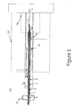
- An embodiment of this invention provides a material handling device 100 and associated method.
- the device 100 as illustrated in Figure 1 comprises a counter rotating double screw feeder 3 that is operably connected to a storage device, such as, but not limited to, a hopper 1, which contains powder, here silicon powder or fines 2.
- the hopper 1 comprises an open bottom that is open to the outer most feed screw 4, which rotates in such a direction that carries fine silicon powder into a hot zone 151 (the hot zone defined as a portion of the furnace 150 where the temperature is greater than about 1415°C) of a receiver, such as, but not limited to, a furnace 150
- the hopper 1 can feed powder, such as silicon 2 to the counter rotating double screw feeder 3.
- the counter rotating double screw feeder 3, as embodied by the invention, comprises an outer screw feed member 4 and an inner screw feed member 5.
- the outer screw feed member 4 is a hollow screw feed member with central bore there through which the inner screw feed member 5 is positioned.
- the outer screw feed member 4 is positioned in an outer screw feed member tube 8, while the inner screw feed member 5 is positioned in an inner screw feed member tube 9.
- the inner screw feed member tube 9 is formed as part of the outer screw feed member 4, either as element formed at the same time or formed separately and them joined as a single piece. For example, these elements can be machined out of one piece of silicon nitride (Si3N4).
- Each of the outer screw feed member 4, inner screw feed member 5, outer screw feed member tube 8, and inner screw feed member tube 9 are aligned on an axis 10, so as to be coaxial in process tube 6.
- the counter rotating double screw feeder 3 and its associated elements are positioned in process tube 6; in a material handling orientation with the hopper 2 and a collection chamber 14 (to be described hereinafter).
- the material handling orientation allows flow of the silicon 2 into the counter rotating double screw feeder 3, either under the flow of gravity, with an assist (positive pressure on the powder 2, such as silicon, force applied to a top surface of the silicon 2, agitation of the powder 2 and/or hopper 1, or the like assistance) or combinations thereof.
- the material handling orientation also allows the collection chamber 14 to collect and separate silicon oxide from process gas a furnace 150 (in phantom) through the inner screw feed member 5 and the inner screw feed member tube 9.
- the inner screw feed member 5 rotates in a direction opposite to the outer screw member 4, such that the inner screw member 5 acts to remove condensed silicon oxide condensing in inner screw feed member tube 9 which acts as process gas outlet. It is desirable for SiO to condense in inner screw feed member 5 rather than on other parts of the furnace, the feedstock or the final product.
- the counter rotating double screw feed device is formed from a material or materials that allows for efficient and effective transfer of silicon powder, for example silicon 2, to the furnace 150 from the hopper 1, as well allow for the return of process gas and condensed solids (such as SiO) from the furnace.
- the ceramic material of the outer screw feed member 4, inner screw feed member 5, outer screw feed member tube 8, and inner screw feed member tube 9 can also be, but are not limited to, Si 3 N 4 , SiC, Al 2 O 3 , Si, SiO 2 and combinations thereof, or similar materials.
- counter rotating double screw feeder 3 as embodied by the invention extends into the furnace 150 to simultaneously load powder 2 into the process tube 6 and extract byproduct process gases from the process tube 6.
- the outer guide tube 8 of the counter rotating double screw feeder 3 extend only partly into the furnace 150 hot zone 151 and is extended by a flared discharge end 7.
- the flared discharge end 7, as embodied by the invention, is provided to avoid compacting of the powder 2 inside outer guide tube 4 where no outer screw feed member 4 is present.
- Inner screw feed member 5, inner screw feed member tube 9, extend beyond the end of flared discharge tube 7 to prevent silicon powder deposited into process tube 6 from being carried out of process tube 6 along with the process gas, as illustrated in Figure 1 .
- the outer screw feed member 4, inner screw feed member 5, outer screw feed member tube 8, and inner screw feed member tube 9 of the counter rotating double screw feeder 3 could extend all the way into the hot zone 151, with further enhancements of materials.
- any and all of the outer screw feed member 4, inner screw feed member 5, outer screw feed member tube 8, and inner screw feed member tube 9 of the counter rotating double screw feeder 3 can be coated with temperature resistant coatings.
- the silicon powder 2 will react in the furnace 150 with any available source of oxygen, such as quartz to form furnace byproducts, such as, but not limited to, silicon oxides (SiO, SiO 2 , or SiO x ), hereinafter "silicon oxides. Any formed silicon oxide will condense right below the melting point of silicon. This silicon oxide condensate is not desirable in the system 100, as it may adversely affect the flow of powder 2, such as, but not limited to, silicon to the furnace 150 and/or the return of gas back through the counter rotating double screw feeder 3, as well as deposit on finished product. Accordingly, as embodied by the invention, the system 100 provides structure and operations to extract process gas, which contains the powder, such as but not limited to silicon oxide, from the furnace 150.
- process gas which contains the powder, such as but not limited to silicon oxide
- the counter rotating double screw feeder 3 provides the outer screw feed member 4 moving the powder 2 from the hopper 1 into the furnace by rotating in one direction in its outer screw feed member tube 8, while the inner screw feed member 5 in its inner screw feed member tube 9 rotates in an opposite or counter direction in the counter rotating double screw feeder 3.
- the inner screw feed member 5 can break up, and if necessary, convey out any silicon oxide that deposits/condenses inside the outer screw feed member tube 8.
- the inner screw 5 could be replaced with a stationary scraping device using the relative motion of the outer screw member 4, which also acts as the inner screw feed member tube 9 to break up silicon oxide deposit inside the inner tube member 9.
- the collection chamber 14 provides for the removal of collected byproducts from the process gas, which can then be, discharged ore recycled.
- the collection chamber 14 may be formed as a velocity drop box that can separate powder from gas.
- the collection chamber 14 may comprise a collection chamber 14 with an access port 15 for the collection of byproducts, where the byproducts can settle under the influence of gravity.
- the collection chamber 14 includes a vent or other process gas port 19, for the removal of process gas from the collection chamber 14.
- the process gas port 19 of the collection chamber 14 may comprise at least one of a vent to atmosphere, a vent to processing or scrubbing equipment (not illustrated), and a pressure assist device, such as, but not limited to, a vacuum removal device (not illustrated).
- a pressure assist device such as, but not limited to, a vacuum removal device (not illustrated).
- the collected byproducts can be periodically removed from the collection chamber 14, or alternatively continuously removed from the collection chamber 14, for example, but not limited to, a conveyor or like removal device (not illustrated).
- the exhaust gas can be bubbled through a liquid to strip off any solids, such as silicon oxide. The liquid could be replace continuously, or discontinuously.
- the counter rotating double screw feeder 3, as embodied by the invention, can be oriented at a slight angle ⁇ to an orthogonal of the system 100 with respect to the hopper 1.
- the slight angle ⁇ with which the counter rotating double screw feeder 3 is positioned to the hopper 1 can be provided by at least one of positioning process tube 6 at the slight angle ⁇ with respect to the hopper 1, positioning the outer screw feed member 4, inner screw feed member 5, outer screw feed member tube 8, and inner screw feed member tube 9 at the slight angle ⁇ with respect to at least one of the hopper 1 and the process tube 6, or combinations thereof.
- the slight angle ⁇ assists in the discharge of powder 2 through the counter rotating double screw feeder 3 and the discharge tube 6 and into the furnace 150.
- the angle ⁇ provides the counter rotating double screw feeder 3 at a small angle, such as an angle ⁇ less than about 10 degrees from orthogonal. Further, as embodied by the invention, the angle ⁇ can be less than about 10 degrees from orthogonal. Furthermore, the angle ⁇ can be between about 0.5 degree to about 3 degrees from orthogonal.
- the furnace 150 can be positioned at an angle ⁇ to from system orthogonal, to assist in the discharge of liquefied silicon from the furnace 150.
- the furnace 150 being positioned at an angle ⁇ to from orthogonal, assists in the discharge of liquefied silicon as a process control of the powder 2 delivery to the furnace 150 and the liquefaction process in the furnace 150 and also a discharge of liquefied silicon from the furnace 150.
- the furnace 150 may have its angle ⁇ adjustable to further assist in the discharge of liquefied silicon from the furnace 150, and its function as a process control.
- the furnace 150 may have its angle ⁇ adjustable by any appropriate means, such as, but not limited to, positioning the furnace 150 on a lift, movable skid, tiltable platform, movable mount or the like, which enables relative movement of the furnace 150 with respect to the system 100.
- various aspects of the invention further contemplate that the system 100 may be adjustable to further assist in the discharge of liquefied silicon from the furnace 150, and its function as a process control. As such, the system 100 may be adjustable to further assist in the discharge of liquefied silicon from the furnace 150 via similar means as the adjustability of the furnace 150.
- the angle ⁇ is also adjustable with respect to the counter rotating double screw feeder 3 and the remainder of the system orthogonal.
- a collar baffle 16 ( Figures 1 and 6 ) can be placed inside the process tube 6.
- the collar baffle 16 can be attached to the process tube 6 by appropriate means, such as, but not limited to welding the collar baffle 16 to the process tube 6, friction fit in the process tube 6, mechanically connecting, or otherwise fit in the process tube 6 by other means.
- the collar baffle 16 is formed with collar baffle cut-outs 18 for acceptance of stabilizing guide rods 18, as discussed hereinafter. Further, as embodied by the invention, the collar baffle 16 is formed from a material that does not adversely affect the operation of the system 100, and its components, as described herein.
- the collar baffle 16 comprises quartz or quartz materials.
- the collar baffle 16, as embodied by the invention can be formed as a separate element from the counter rotating double screw feeder 3 and the process tube 6, and slid over the counter rotating double screw feeder 3 with an aperture 17 formed in the collar baffle 16 accepting the counter rotating double screw feeder 3.
- the cut-outs 18' accept stabilizing guide rods 18, thus positioning the collar baffle 16 in the process tube 6.
- the collar baffle 16 can be inserted on the process tube 6 as a separate element, and can be removed when any part of the counter rotating double screw feeder 3 or the process tube 6 needs maintenance or replacement.
- the process tube 6 may comprise stabilizing structure therein.
- the stabilizing structure can comprise stabilizing guide structures or stabilizing guide rods 18. These stabilizing guide rods 18 are positioned on the interior periphery of the process tube 6, as schematically illustrated in Figure 5 .
- the stabilizing guide 18 can be formed as quartz rods 18 positioned on the inside of the process tube 6. As illustrated there are few guide rods 18 positioned on the interior of the process tube 6, and while illustrated as circular in cross section, these stabilizing guide rods 18 can have any stabilizing configuration, such as, but not limited to, rectangular, triangular, "I"-beam, or any other such configuration that provides stabilization.
- the stabilizing guide rods 18 connected to the process tube 6 will guide the collar baffle 16 through cooperation with the collar baffle cut-outs 18', thus keeping the collar baffle 16 in place in the process tube as the while the counter rotating double screw feeder 3 and its components rotate.
- the counter rotating double screw feeder 3 inner screw feed member 5, which is acting to remove condensed silicon oxide and gas from the furnace 150 can be actively cooled.
- the cooling of the inner screw feed member 5 can be by appropriate cooling means (not illustrated for facilitating understanding aspects of the invention), such as, but not limited to, cooling with gas or liquid coolant.
- the inner screw feed member tube 9 that separates the outer screw feed member 4 from the inner screw feed member 5 can be constructed to insulate the inner screw feed member 5 from the process tube 6, especially where the process tube 6 extends into the furnace 150. Accordingly, an inner surface of the inner screw feed member tube 9 would be cooler than its outer surface, encouraging condensation on the inner surface, where the inner screw feed member 5 can easily remove the condensation.
- the system 100 can feed powder into a hot zone 151 of a furnace 150, such as, but not limited to, a rotary furnace.
- a furnace 150 such as, but not limited to, a rotary furnace.
- the system 100 allows for the extraction of gas from the furnace 150 preventing powder from backing up in the process tube 6. Accordingly, the system 100 permits long term or continuous operation in an environment where powder 2 is fed into a furnace.
- the system 100 can be used to feed silicon powder 2 into a furnace 150 for forming materials, such as, but not limited to, high purity molten silicon.
- the high purity silicon can be used for forming photovoltaic devices, panels, solar panels or other devices that employ such silicon.
- the system 100 with the flared end 7 of the outer tube member 8 allows material to be fed directly into the furnace 150 without requiring the outer screw member 4 to be extended fully into the furnace 150 hot zone 151.
- the flared end 7 can prevent packing of the powder 2, which pack and jam inside the outer tube member 8.
- the counter rotating double screw feeder 3 with the outer screw feed member 4 and inner screw feed member 5 rotating counter to the outer screw feed member 4 can allow gas and powder to be extracted in a system with only one access point available.
- the inner screw feed member 5 and its inner screw feed member tube 9 could be placed at a point of entry, remote from the outer screw feed member 4 and its outer screw feed member tube 8, where each communicates with the furnace 150, such as at a location on the furnace 150 proximate where the molten silicon exits.
- Placing the inner screw feed member 5 as illustrated, as shown, is preferred, and the byproducts, such as, but not limited to, silicon oxide, will be formed that end, and single rotating double screw feeder 3 for both feeding powder and extracting byproducts allows for enhanced management of the equipment for cleaning, maintenance, and replacement of consumable parts.
- the collar baffle 16 as embodied by the invention, can prevent powder 2 from backing up in at least one of the process tube 6 and or the counter rotating double screw feeder 3 towards the end of the tube that is remote from the furnace 150, where backing up could be disruptive and result in shutting down the system 100. Also, providing the collar baffle 16 as a modular unit insertable into the system 100, as described above, can allow for in-situ cleaning of the system 100.
Landscapes
- Engineering & Computer Science (AREA)
- Chemical & Material Sciences (AREA)
- Crystallography & Structural Chemistry (AREA)
- Materials Engineering (AREA)
- Metallurgy (AREA)
- Organic Chemistry (AREA)
- Mechanical Engineering (AREA)
- General Engineering & Computer Science (AREA)
- Silicon Compounds (AREA)
- Screw Conveyors (AREA)
- Filling Or Emptying Of Bunkers, Hoppers, And Tanks (AREA)
Claims (8)
- Materialhandhabungssystem (100) zum Transportieren von Siliziumpulver aus einer Lagervorrichtung zu einem Ofen (150), wobei das System aufweist:einen gegenläufigen Doppelschneckenförderer (3), der sich von der Lagervorrichtung zu dem Empfänger erstreckt; wobei der gegenläufige Doppelschneckenförderer aufweist:ein äußeres Schneckenförderelement (4);ein inneres Schneckenförderelement (5);wobei das äußere Schneckenförderelement in einem äußeren Schneckenförderelementrohr (8) positioniert ist,während das innere Schneckenförderelement in einem inneren Schneckenförderelementrohr (9) positioniert ist;ein Prozessrohr (6), das den gegenläufigen Doppelschneckenförderer in einer Materialhandhabungsausrichtung zu der Lagervorrichtung und dem Empfänger positioniert; wobei Material (2) aus der Lagervorrichtung dem Empfänger über das äußere Schneckenförderelement zugeführt wird, während das innere Schneckenförderelement Gas und Nebenprodukte aus dem Empfänger abführt;wobei das äußere Schneckenförderelement (4) ein Hohlschneckenförderelement mit einer dadurch verlaufenden Mittenbohrung aufweist, und das innere Schneckenförderelement (5) in der Mittenbohrung positioniert ist; unddadurch gekennzeichnet, dass:das äußere Schneckenförderelement (4), das innere Schneckenförderelement (5), das äußere Schneckenförderelementrohr (8) und das innere Schneckenförderelementrohr (9) aus einem keramischen Material ausgebildet sind, wobei das keramische Material aus der aus Si3N4, SiC, Al2O3, Si, SiO2 und Kombinationen davon bestehenden Gruppe ausgewählt ist.
- System (100) nach Anspruch 1, wobei alle von dem äußeren Schneckenförderelement (4), dem inneren Schneckenförderelement (5), dem äußeren Schneckenförderelementrohr (8) und dem inneren Schneckenförderelementrohr (9) zu einer gemeinsamen Achse ausgerichtet ist.
- System (100) nach einem der vorstehenden Ansprüche, wobei alle von dem äußeren Schneckenförderelement (4), dem inneren Schneckenförderelement (5), dem äußeren Schneckenförderelementrohr (8) und dem inneren Schneckenförderelementrohr (9) koaxial in dem Prozessrohr (6) ausgerichtet sind.
- System (100) nach einem der vorstehenden Ansprüche, wobei das innere Schneckenförderelementrohr (9) einen Teil des äußeren Schneckenförderelementes aufweist.
- System (100) nach einem der vorstehenden Ansprüche, wobei das innere Schneckenförderelementrohr (9) und das äußere Schneckenförderelement (4) aus einem einzigen Teil Siliziumnitrid (SiN) herausgearbeitet sind, wobei das innere Schneckenförderelementrohr eine Welle des äußeren Schneckenförderelementes bildet.
- System (100) nach einem der vorstehenden Ansprüche, wobei der Empfänger einen Ofen (150) aufweist und das Material Siliziumpulver aufweist, sodass der Ofen das Siliziumpulver schmilzt und das innere Schneckenförderelement (5) Gas und Siliziumoxidnebenprodukte aus dem Ofen abführt.
- System (100) nach einem der vorstehenden Ansprüche, wobei der gegenläufige Doppelschneckenförderer (3) und das ausgestellte Auslassende des Prozessrohres eine heiße Zone (151) des Ofens (150) erweitert.
- System (100) nach Anspruch 6 oder Anspruch 7, wobei wenigstens eine(r) von dem gegenläufigen Doppelschneckenförderer (3), dem Ofen (150) und der Lagervorrichtung (1) in Winkeln (α) zu wenigstens einem von allen anderen und zu einer Systemorthogonalen angeordnet ist (sind), um den Transport des Siliziumpulvers aus der Lagervorrichtung durch den gegenläufigen Doppelschneckenförderer zu dem Ofen (150) zu ermöglichen.
Applications Claiming Priority (1)
| Application Number | Priority Date | Filing Date | Title |
|---|---|---|---|
| US12/173,248 US7975833B2 (en) | 2008-07-15 | 2008-07-15 | Material handling system and method |
Publications (2)
| Publication Number | Publication Date |
|---|---|
| EP2146168A1 EP2146168A1 (de) | 2010-01-20 |
| EP2146168B1 true EP2146168B1 (de) | 2012-02-01 |
Family
ID=41060055
Family Applications (1)
| Application Number | Title | Priority Date | Filing Date |
|---|---|---|---|
| EP09164967A Not-in-force EP2146168B1 (de) | 2008-07-15 | 2009-07-08 | Materialhandhabungssystem für Siliziumpulver |
Country Status (6)
| Country | Link |
|---|---|
| US (1) | US7975833B2 (de) |
| EP (1) | EP2146168B1 (de) |
| CN (1) | CN101628659B (de) |
| AT (1) | ATE544042T1 (de) |
| AU (1) | AU2009202586A1 (de) |
| ES (1) | ES2378745T3 (de) |
Families Citing this family (7)
| Publication number | Priority date | Publication date | Assignee | Title |
|---|---|---|---|---|
| JP3868757B2 (ja) * | 2001-04-25 | 2007-01-17 | 株式会社神戸製鋼所 | ゴム系組成物の混練装置および混練方法 |
| CN102211706A (zh) * | 2010-04-02 | 2011-10-12 | 张岩 | 一种双向搅龙 |
| CN101897551B (zh) * | 2010-05-21 | 2012-11-21 | 九阳股份有限公司 | 一种进料可调的多功能食品加工机及进料装置 |
| CN104828488B (zh) * | 2015-05-08 | 2017-03-29 | 青岛理工大学 | 一种内外双螺旋式滚筒传送装置 |
| CN106753442A (zh) * | 2017-01-19 | 2017-05-31 | 青岛科技大学 | 一种秸秆连续炭化防结碳装置 |
| DE102018132082A1 (de) * | 2018-12-13 | 2020-06-18 | HKR Beteiligungs GmbH | Schneckenförderer; Pyrolyseanlage; Verfahren zur Pyrolysierung eines Materials mittels eines beheizbaren Pyrolysereaktors |
| CN110803538A (zh) * | 2019-12-06 | 2020-02-18 | 深圳市山龙智控有限公司 | 一种螺丝补料器 |
Family Cites Families (6)
| Publication number | Priority date | Publication date | Assignee | Title |
|---|---|---|---|---|
| DE538426C (de) | 1929-07-11 | 1931-11-14 | Arno Andreas | Oberer Drehrohrofenabschluss mit Schraubengaengen |
| JP2500277B2 (ja) * | 1990-11-27 | 1996-05-29 | 三井東圧化学株式会社 | フェノ―ル系樹脂パイプの押出成型方法および装置 |
| DE4116215A1 (de) | 1991-05-17 | 1992-11-19 | Hilti Ag | Trommelfoermige transporteinrichtung |
| US5743471A (en) * | 1993-08-02 | 1998-04-28 | Illinois Institute Of Technology | Solid state shear extrusion pulverization |
| US6193053B1 (en) * | 2000-03-31 | 2001-02-27 | Mark K. Gaalswyk | Concentric auger feeder |
| US6939490B2 (en) * | 2002-12-11 | 2005-09-06 | Honeywell International Inc. | Process for unidirectional infiltration of preform with molten resin or pitch |
-
2008
- 2008-07-15 US US12/173,248 patent/US7975833B2/en not_active Expired - Fee Related
-
2009
- 2009-06-26 AU AU2009202586A patent/AU2009202586A1/en not_active Abandoned
- 2009-07-08 ES ES09164967T patent/ES2378745T3/es active Active
- 2009-07-08 AT AT09164967T patent/ATE544042T1/de active
- 2009-07-08 EP EP09164967A patent/EP2146168B1/de not_active Not-in-force
- 2009-07-15 CN CN200910164608.7A patent/CN101628659B/zh not_active Expired - Fee Related
Also Published As
| Publication number | Publication date |
|---|---|
| EP2146168A1 (de) | 2010-01-20 |
| US7975833B2 (en) | 2011-07-12 |
| US20100012468A1 (en) | 2010-01-21 |
| ATE544042T1 (de) | 2012-02-15 |
| CN101628659A (zh) | 2010-01-20 |
| ES2378745T3 (es) | 2012-04-17 |
| AU2009202586A1 (en) | 2010-02-04 |
| CN101628659B (zh) | 2013-08-21 |
Similar Documents
| Publication | Publication Date | Title |
|---|---|---|
| EP2146168B1 (de) | Materialhandhabungssystem für Siliziumpulver | |
| US8734563B2 (en) | Method and plant for the production of zinc dust | |
| CN104148660B (zh) | 金属粉末制造用等离子体装置及金属粉末的制造方法 | |
| EP1273330B1 (de) | Verfahren und vorrichtung zur reinigung durch sublimation | |
| EP1807194B1 (de) | Mit solar-energie betriebener rotierender reaktor | |
| CA1075325A (en) | Plasma reactor and procedure for reduction of metal oxides | |
| JP5859577B2 (ja) | シリコン精製装置及びシリコン精製方法 | |
| US9970076B2 (en) | Method of apparatus for condensing metal vapours using a nozzle and a molten collector | |
| KR101047842B1 (ko) | 기상으로부터 초미립자를 퇴적시키는 장치 및 방법 | |
| EP2738146B1 (de) | Zementanlage | |
| KR900002522B1 (ko) | 유리배치 물질을 가열 용기로 이송하는 방법과 분말 물질을 액화하는 장치. | |
| US4678491A (en) | Reduction of material buildup by means of gas jet | |
| JP6028702B2 (ja) | 酸化珪素の製造方法 | |
| US10022697B2 (en) | Arc reactor and process for producing nanoparticles | |
| JPS6395121A (ja) | 予熱段階及び液化段階の間のガラスバッチの移送装置 | |
| RU2336347C1 (ru) | Устройство для получения слитков дистиллированного кальция | |
| CN115385340A (zh) | 一种低品位硅材料的提纯装置及方法 |
Legal Events
| Date | Code | Title | Description |
|---|---|---|---|
| PUAI | Public reference made under article 153(3) epc to a published international application that has entered the european phase |
Free format text: ORIGINAL CODE: 0009012 |
|
| AK | Designated contracting states |
Kind code of ref document: A1 Designated state(s): AT BE BG CH CY CZ DE DK EE ES FI FR GB GR HR HU IE IS IT LI LT LU LV MC MK MT NL NO PL PT RO SE SI SK SM TR |
|
| 17P | Request for examination filed |
Effective date: 20100720 |
|
| 17Q | First examination report despatched |
Effective date: 20101214 |
|
| GRAP | Despatch of communication of intention to grant a patent |
Free format text: ORIGINAL CODE: EPIDOSNIGR1 |
|
| RTI1 | Title (correction) |
Free format text: MATERIAL HANDLING SYSTEM FOR MOVING SILICON POWDER |
|
| GRAS | Grant fee paid |
Free format text: ORIGINAL CODE: EPIDOSNIGR3 |
|
| GRAA | (expected) grant |
Free format text: ORIGINAL CODE: 0009210 |
|
| AK | Designated contracting states |
Kind code of ref document: B1 Designated state(s): AT BE BG CH CY CZ DE DK EE ES FI FR GB GR HR HU IE IS IT LI LT LU LV MC MK MT NL NO PL PT RO SE SI SK SM TR |
|
| REG | Reference to a national code |
Ref country code: GB Ref legal event code: FG4D |
|
| REG | Reference to a national code |
Ref country code: AT Ref legal event code: REF Ref document number: 544042 Country of ref document: AT Kind code of ref document: T Effective date: 20120215 Ref country code: CH Ref legal event code: EP |
|
| REG | Reference to a national code |
Ref country code: DE Ref legal event code: R096 Ref document number: 602009005000 Country of ref document: DE Effective date: 20120405 |
|
| REG | Reference to a national code |
Ref country code: ES Ref legal event code: FG2A Ref document number: 2378745 Country of ref document: ES Kind code of ref document: T3 Effective date: 20120417 |
|
| REG | Reference to a national code |
Ref country code: NL Ref legal event code: VDEP Effective date: 20120201 |
|
| LTIE | Lt: invalidation of european patent or patent extension |
Effective date: 20120201 |
|
| PG25 | Lapsed in a contracting state [announced via postgrant information from national office to epo] |
Ref country code: HR Free format text: LAPSE BECAUSE OF FAILURE TO SUBMIT A TRANSLATION OF THE DESCRIPTION OR TO PAY THE FEE WITHIN THE PRESCRIBED TIME-LIMIT Effective date: 20120201 Ref country code: IS Free format text: LAPSE BECAUSE OF FAILURE TO SUBMIT A TRANSLATION OF THE DESCRIPTION OR TO PAY THE FEE WITHIN THE PRESCRIBED TIME-LIMIT Effective date: 20120601 Ref country code: LT Free format text: LAPSE BECAUSE OF FAILURE TO SUBMIT A TRANSLATION OF THE DESCRIPTION OR TO PAY THE FEE WITHIN THE PRESCRIBED TIME-LIMIT Effective date: 20120201 Ref country code: NO Free format text: LAPSE BECAUSE OF FAILURE TO SUBMIT A TRANSLATION OF THE DESCRIPTION OR TO PAY THE FEE WITHIN THE PRESCRIBED TIME-LIMIT Effective date: 20120501 Ref country code: NL Free format text: LAPSE BECAUSE OF FAILURE TO SUBMIT A TRANSLATION OF THE DESCRIPTION OR TO PAY THE FEE WITHIN THE PRESCRIBED TIME-LIMIT Effective date: 20120201 |
|
| PG25 | Lapsed in a contracting state [announced via postgrant information from national office to epo] |
Ref country code: PL Free format text: LAPSE BECAUSE OF FAILURE TO SUBMIT A TRANSLATION OF THE DESCRIPTION OR TO PAY THE FEE WITHIN THE PRESCRIBED TIME-LIMIT Effective date: 20120201 Ref country code: BE Free format text: LAPSE BECAUSE OF FAILURE TO SUBMIT A TRANSLATION OF THE DESCRIPTION OR TO PAY THE FEE WITHIN THE PRESCRIBED TIME-LIMIT Effective date: 20120201 Ref country code: LV Free format text: LAPSE BECAUSE OF FAILURE TO SUBMIT A TRANSLATION OF THE DESCRIPTION OR TO PAY THE FEE WITHIN THE PRESCRIBED TIME-LIMIT Effective date: 20120201 Ref country code: PT Free format text: LAPSE BECAUSE OF FAILURE TO SUBMIT A TRANSLATION OF THE DESCRIPTION OR TO PAY THE FEE WITHIN THE PRESCRIBED TIME-LIMIT Effective date: 20120601 Ref country code: GR Free format text: LAPSE BECAUSE OF FAILURE TO SUBMIT A TRANSLATION OF THE DESCRIPTION OR TO PAY THE FEE WITHIN THE PRESCRIBED TIME-LIMIT Effective date: 20120502 Ref country code: FI Free format text: LAPSE BECAUSE OF FAILURE TO SUBMIT A TRANSLATION OF THE DESCRIPTION OR TO PAY THE FEE WITHIN THE PRESCRIBED TIME-LIMIT Effective date: 20120201 |
|
| REG | Reference to a national code |
Ref country code: AT Ref legal event code: MK05 Ref document number: 544042 Country of ref document: AT Kind code of ref document: T Effective date: 20120201 |
|
| PG25 | Lapsed in a contracting state [announced via postgrant information from national office to epo] |
Ref country code: CY Free format text: LAPSE BECAUSE OF FAILURE TO SUBMIT A TRANSLATION OF THE DESCRIPTION OR TO PAY THE FEE WITHIN THE PRESCRIBED TIME-LIMIT Effective date: 20120201 |
|
| PG25 | Lapsed in a contracting state [announced via postgrant information from national office to epo] |
Ref country code: RO Free format text: LAPSE BECAUSE OF FAILURE TO SUBMIT A TRANSLATION OF THE DESCRIPTION OR TO PAY THE FEE WITHIN THE PRESCRIBED TIME-LIMIT Effective date: 20120201 Ref country code: EE Free format text: LAPSE BECAUSE OF FAILURE TO SUBMIT A TRANSLATION OF THE DESCRIPTION OR TO PAY THE FEE WITHIN THE PRESCRIBED TIME-LIMIT Effective date: 20120201 Ref country code: SE Free format text: LAPSE BECAUSE OF FAILURE TO SUBMIT A TRANSLATION OF THE DESCRIPTION OR TO PAY THE FEE WITHIN THE PRESCRIBED TIME-LIMIT Effective date: 20120201 Ref country code: DK Free format text: LAPSE BECAUSE OF FAILURE TO SUBMIT A TRANSLATION OF THE DESCRIPTION OR TO PAY THE FEE WITHIN THE PRESCRIBED TIME-LIMIT Effective date: 20120201 Ref country code: CZ Free format text: LAPSE BECAUSE OF FAILURE TO SUBMIT A TRANSLATION OF THE DESCRIPTION OR TO PAY THE FEE WITHIN THE PRESCRIBED TIME-LIMIT Effective date: 20120201 Ref country code: SI Free format text: LAPSE BECAUSE OF FAILURE TO SUBMIT A TRANSLATION OF THE DESCRIPTION OR TO PAY THE FEE WITHIN THE PRESCRIBED TIME-LIMIT Effective date: 20120201 |
|
| PG25 | Lapsed in a contracting state [announced via postgrant information from national office to epo] |
Ref country code: SK Free format text: LAPSE BECAUSE OF FAILURE TO SUBMIT A TRANSLATION OF THE DESCRIPTION OR TO PAY THE FEE WITHIN THE PRESCRIBED TIME-LIMIT Effective date: 20120201 |
|
| PLBE | No opposition filed within time limit |
Free format text: ORIGINAL CODE: 0009261 |
|
| STAA | Information on the status of an ep patent application or granted ep patent |
Free format text: STATUS: NO OPPOSITION FILED WITHIN TIME LIMIT |
|
| 26N | No opposition filed |
Effective date: 20121105 |
|
| PG25 | Lapsed in a contracting state [announced via postgrant information from national office to epo] |
Ref country code: AT Free format text: LAPSE BECAUSE OF FAILURE TO SUBMIT A TRANSLATION OF THE DESCRIPTION OR TO PAY THE FEE WITHIN THE PRESCRIBED TIME-LIMIT Effective date: 20120201 |
|
| PG25 | Lapsed in a contracting state [announced via postgrant information from national office to epo] |
Ref country code: MC Free format text: LAPSE BECAUSE OF NON-PAYMENT OF DUE FEES Effective date: 20120731 Ref country code: MK Free format text: LAPSE BECAUSE OF FAILURE TO SUBMIT A TRANSLATION OF THE DESCRIPTION OR TO PAY THE FEE WITHIN THE PRESCRIBED TIME-LIMIT Effective date: 20120201 |
|
| REG | Reference to a national code |
Ref country code: DE Ref legal event code: R097 Ref document number: 602009005000 Country of ref document: DE Effective date: 20121105 |
|
| REG | Reference to a national code |
Ref country code: FR Ref legal event code: ST Effective date: 20130329 |
|
| PG25 | Lapsed in a contracting state [announced via postgrant information from national office to epo] |
Ref country code: FR Free format text: LAPSE BECAUSE OF NON-PAYMENT OF DUE FEES Effective date: 20120731 |
|
| REG | Reference to a national code |
Ref country code: IE Ref legal event code: MM4A |
|
| PG25 | Lapsed in a contracting state [announced via postgrant information from national office to epo] |
Ref country code: MT Free format text: LAPSE BECAUSE OF FAILURE TO SUBMIT A TRANSLATION OF THE DESCRIPTION OR TO PAY THE FEE WITHIN THE PRESCRIBED TIME-LIMIT Effective date: 20120201 Ref country code: BG Free format text: LAPSE BECAUSE OF FAILURE TO SUBMIT A TRANSLATION OF THE DESCRIPTION OR TO PAY THE FEE WITHIN THE PRESCRIBED TIME-LIMIT Effective date: 20120501 Ref country code: IE Free format text: LAPSE BECAUSE OF NON-PAYMENT OF DUE FEES Effective date: 20120708 |
|
| REG | Reference to a national code |
Ref country code: CH Ref legal event code: PL |
|
| GBPC | Gb: european patent ceased through non-payment of renewal fee |
Effective date: 20130708 |
|
| PG25 | Lapsed in a contracting state [announced via postgrant information from national office to epo] |
Ref country code: TR Free format text: LAPSE BECAUSE OF FAILURE TO SUBMIT A TRANSLATION OF THE DESCRIPTION OR TO PAY THE FEE WITHIN THE PRESCRIBED TIME-LIMIT Effective date: 20120201 Ref country code: GB Free format text: LAPSE BECAUSE OF NON-PAYMENT OF DUE FEES Effective date: 20130708 Ref country code: LI Free format text: LAPSE BECAUSE OF NON-PAYMENT OF DUE FEES Effective date: 20130731 Ref country code: CH Free format text: LAPSE BECAUSE OF NON-PAYMENT OF DUE FEES Effective date: 20130731 |
|
| PG25 | Lapsed in a contracting state [announced via postgrant information from national office to epo] |
Ref country code: SM Free format text: LAPSE BECAUSE OF FAILURE TO SUBMIT A TRANSLATION OF THE DESCRIPTION OR TO PAY THE FEE WITHIN THE PRESCRIBED TIME-LIMIT Effective date: 20120201 Ref country code: LU Free format text: LAPSE BECAUSE OF NON-PAYMENT OF DUE FEES Effective date: 20120708 |
|
| PG25 | Lapsed in a contracting state [announced via postgrant information from national office to epo] |
Ref country code: HU Free format text: LAPSE BECAUSE OF FAILURE TO SUBMIT A TRANSLATION OF THE DESCRIPTION OR TO PAY THE FEE WITHIN THE PRESCRIBED TIME-LIMIT Effective date: 20090708 |
|
| PGFP | Annual fee paid to national office [announced via postgrant information from national office to epo] |
Ref country code: DE Payment date: 20140729 Year of fee payment: 6 |
|
| PGFP | Annual fee paid to national office [announced via postgrant information from national office to epo] |
Ref country code: ES Payment date: 20140728 Year of fee payment: 6 |
|
| PGFP | Annual fee paid to national office [announced via postgrant information from national office to epo] |
Ref country code: IT Payment date: 20140722 Year of fee payment: 6 |
|
| REG | Reference to a national code |
Ref country code: DE Ref legal event code: R119 Ref document number: 602009005000 Country of ref document: DE |
|
| PG25 | Lapsed in a contracting state [announced via postgrant information from national office to epo] |
Ref country code: IT Free format text: LAPSE BECAUSE OF NON-PAYMENT OF DUE FEES Effective date: 20150708 Ref country code: DE Free format text: LAPSE BECAUSE OF NON-PAYMENT OF DUE FEES Effective date: 20160202 |
|
| REG | Reference to a national code |
Ref country code: ES Ref legal event code: FD2A Effective date: 20161228 |
|
| PG25 | Lapsed in a contracting state [announced via postgrant information from national office to epo] |
Ref country code: ES Free format text: LAPSE BECAUSE OF NON-PAYMENT OF DUE FEES Effective date: 20150709 |