EP2144236A1 - System und Vorrichtung zur Aufzeichnung von Daten auf einem Informationsspeichermedium - Google Patents
System und Vorrichtung zur Aufzeichnung von Daten auf einem Informationsspeichermedium Download PDFInfo
- Publication number
- EP2144236A1 EP2144236A1 EP09173681A EP09173681A EP2144236A1 EP 2144236 A1 EP2144236 A1 EP 2144236A1 EP 09173681 A EP09173681 A EP 09173681A EP 09173681 A EP09173681 A EP 09173681A EP 2144236 A1 EP2144236 A1 EP 2144236A1
- Authority
- EP
- European Patent Office
- Prior art keywords
- data
- storage medium
- area
- information storage
- lead
- Prior art date
- Legal status (The legal status is an assumption and is not a legal conclusion. Google has not performed a legal analysis and makes no representation as to the accuracy of the status listed.)
- Granted
Links
Images


Classifications
-
- G—PHYSICS
- G11—INFORMATION STORAGE
- G11B—INFORMATION STORAGE BASED ON RELATIVE MOVEMENT BETWEEN RECORD CARRIER AND TRANSDUCER
- G11B20/00—Signal processing not specific to the method of recording or reproducing; Circuits therefor
- G11B20/10—Digital recording or reproducing
- G11B20/12—Formatting, e.g. arrangement of data block or words on the record carriers
- G11B20/1217—Formatting, e.g. arrangement of data block or words on the record carriers on discs
-
- G—PHYSICS
- G11—INFORMATION STORAGE
- G11B—INFORMATION STORAGE BASED ON RELATIVE MOVEMENT BETWEEN RECORD CARRIER AND TRANSDUCER
- G11B27/00—Editing; Indexing; Addressing; Timing or synchronising; Monitoring; Measuring tape travel
- G11B27/10—Indexing; Addressing; Timing or synchronising; Measuring tape travel
- G11B27/102—Programmed access in sequence to addressed parts of tracks of operating record carriers
- G11B27/105—Programmed access in sequence to addressed parts of tracks of operating record carriers of operating discs
-
- G—PHYSICS
- G11—INFORMATION STORAGE
- G11B—INFORMATION STORAGE BASED ON RELATIVE MOVEMENT BETWEEN RECORD CARRIER AND TRANSDUCER
- G11B7/00—Recording or reproducing by optical means, e.g. recording using a thermal beam of optical radiation by modifying optical properties or the physical structure, reproducing using an optical beam at lower power by sensing optical properties; Record carriers therefor
- G11B7/004—Recording, reproducing or erasing methods; Read, write or erase circuits therefor
- G11B7/0045—Recording
-
- G—PHYSICS
- G11—INFORMATION STORAGE
- G11B—INFORMATION STORAGE BASED ON RELATIVE MOVEMENT BETWEEN RECORD CARRIER AND TRANSDUCER
- G11B7/00—Recording or reproducing by optical means, e.g. recording using a thermal beam of optical radiation by modifying optical properties or the physical structure, reproducing using an optical beam at lower power by sensing optical properties; Record carriers therefor
- G11B7/007—Arrangement of the information on the record carrier, e.g. form of tracks, actual track shape, e.g. wobbled, or cross-section, e.g. v-shaped; Sequential information structures, e.g. sectoring or header formats within a track
- G11B7/00736—Auxiliary data, e.g. lead-in, lead-out, Power Calibration Area [PCA], Burst Cutting Area [BCA], control information
-
- G—PHYSICS
- G11—INFORMATION STORAGE
- G11B—INFORMATION STORAGE BASED ON RELATIVE MOVEMENT BETWEEN RECORD CARRIER AND TRANSDUCER
- G11B7/00—Recording or reproducing by optical means, e.g. recording using a thermal beam of optical radiation by modifying optical properties or the physical structure, reproducing using an optical beam at lower power by sensing optical properties; Record carriers therefor
- G11B7/12—Heads, e.g. forming of the optical beam spot or modulation of the optical beam
- G11B7/125—Optical beam sources therefor, e.g. laser control circuitry specially adapted for optical storage devices; Modulators, e.g. means for controlling the size or intensity of optical spots or optical traces
- G11B7/126—Circuits, methods or arrangements for laser control or stabilisation
- G11B7/1267—Power calibration
-
- G—PHYSICS
- G11—INFORMATION STORAGE
- G11B—INFORMATION STORAGE BASED ON RELATIVE MOVEMENT BETWEEN RECORD CARRIER AND TRANSDUCER
- G11B7/00—Recording or reproducing by optical means, e.g. recording using a thermal beam of optical radiation by modifying optical properties or the physical structure, reproducing using an optical beam at lower power by sensing optical properties; Record carriers therefor
- G11B7/24—Record carriers characterised by shape, structure or physical properties, or by the selection of the material
- G11B7/2403—Layers; Shape, structure or physical properties thereof
- G11B7/24035—Recording layers
- G11B7/24038—Multiple laminated recording layers
-
- G—PHYSICS
- G11—INFORMATION STORAGE
- G11B—INFORMATION STORAGE BASED ON RELATIVE MOVEMENT BETWEEN RECORD CARRIER AND TRANSDUCER
- G11B7/00—Recording or reproducing by optical means, e.g. recording using a thermal beam of optical radiation by modifying optical properties or the physical structure, reproducing using an optical beam at lower power by sensing optical properties; Record carriers therefor
- G11B2007/0003—Recording, reproducing or erasing systems characterised by the structure or type of the carrier
- G11B2007/0009—Recording, reproducing or erasing systems characterised by the structure or type of the carrier for carriers having data stored in three dimensions, e.g. volume storage
- G11B2007/0013—Recording, reproducing or erasing systems characterised by the structure or type of the carrier for carriers having data stored in three dimensions, e.g. volume storage for carriers having multiple discrete layers
-
- G—PHYSICS
- G11—INFORMATION STORAGE
- G11B—INFORMATION STORAGE BASED ON RELATIVE MOVEMENT BETWEEN RECORD CARRIER AND TRANSDUCER
- G11B20/00—Signal processing not specific to the method of recording or reproducing; Circuits therefor
- G11B20/10—Digital recording or reproducing
- G11B20/12—Formatting, e.g. arrangement of data block or words on the record carriers
- G11B20/1217—Formatting, e.g. arrangement of data block or words on the record carriers on discs
- G11B2020/1218—Formatting, e.g. arrangement of data block or words on the record carriers on discs wherein the formatting concerns a specific area of the disc
- G11B2020/1228—Formatting, e.g. arrangement of data block or words on the record carriers on discs wherein the formatting concerns a specific area of the disc middle zone or outer guard area of a multilayer disc
-
- G—PHYSICS
- G11—INFORMATION STORAGE
- G11B—INFORMATION STORAGE BASED ON RELATIVE MOVEMENT BETWEEN RECORD CARRIER AND TRANSDUCER
- G11B20/00—Signal processing not specific to the method of recording or reproducing; Circuits therefor
- G11B20/10—Digital recording or reproducing
- G11B20/12—Formatting, e.g. arrangement of data block or words on the record carriers
- G11B20/1217—Formatting, e.g. arrangement of data block or words on the record carriers on discs
- G11B2020/1218—Formatting, e.g. arrangement of data block or words on the record carriers on discs wherein the formatting concerns a specific area of the disc
- G11B2020/1231—Formatting, e.g. arrangement of data block or words on the record carriers on discs wherein the formatting concerns a specific area of the disc lead-out area
-
- G—PHYSICS
- G11—INFORMATION STORAGE
- G11B—INFORMATION STORAGE BASED ON RELATIVE MOVEMENT BETWEEN RECORD CARRIER AND TRANSDUCER
- G11B20/00—Signal processing not specific to the method of recording or reproducing; Circuits therefor
- G11B20/10—Digital recording or reproducing
- G11B20/12—Formatting, e.g. arrangement of data block or words on the record carriers
- G11B20/1217—Formatting, e.g. arrangement of data block or words on the record carriers on discs
- G11B2020/1218—Formatting, e.g. arrangement of data block or words on the record carriers on discs wherein the formatting concerns a specific area of the disc
- G11B2020/1241—Formatting, e.g. arrangement of data block or words on the record carriers on discs wherein the formatting concerns a specific area of the disc user area, i.e. the area of a disc where user data are to be recorded
-
- G—PHYSICS
- G11—INFORMATION STORAGE
- G11B—INFORMATION STORAGE BASED ON RELATIVE MOVEMENT BETWEEN RECORD CARRIER AND TRANSDUCER
- G11B20/00—Signal processing not specific to the method of recording or reproducing; Circuits therefor
- G11B20/10—Digital recording or reproducing
- G11B20/12—Formatting, e.g. arrangement of data block or words on the record carriers
- G11B2020/1264—Formatting, e.g. arrangement of data block or words on the record carriers wherein the formatting concerns a specific kind of data
- G11B2020/1265—Control data, system data or management information, i.e. data used to access or process user data
- G11B2020/1275—Calibration data, e.g. specific training patterns for adjusting equalizer settings or other recording or playback parameters
-
- G—PHYSICS
- G11—INFORMATION STORAGE
- G11B—INFORMATION STORAGE BASED ON RELATIVE MOVEMENT BETWEEN RECORD CARRIER AND TRANSDUCER
- G11B20/00—Signal processing not specific to the method of recording or reproducing; Circuits therefor
- G11B20/10—Digital recording or reproducing
- G11B20/12—Formatting, e.g. arrangement of data block or words on the record carriers
- G11B2020/1291—Formatting, e.g. arrangement of data block or words on the record carriers wherein the formatting serves a specific purpose
- G11B2020/1294—Increase of the access speed
- G11B2020/1297—Increase of the access speed wherein the focus is on the write access speed
-
- G—PHYSICS
- G11—INFORMATION STORAGE
- G11B—INFORMATION STORAGE BASED ON RELATIVE MOVEMENT BETWEEN RECORD CARRIER AND TRANSDUCER
- G11B2220/00—Record carriers by type
- G11B2220/20—Disc-shaped record carriers
- G11B2220/23—Disc-shaped record carriers characterised in that the disc has a specific layer structure
- G11B2220/235—Multilayer discs, i.e. multiple recording layers accessed from the same side
- G11B2220/237—Multilayer discs, i.e. multiple recording layers accessed from the same side having exactly two recording layers
-
- G—PHYSICS
- G11—INFORMATION STORAGE
- G11B—INFORMATION STORAGE BASED ON RELATIVE MOVEMENT BETWEEN RECORD CARRIER AND TRANSDUCER
- G11B2220/00—Record carriers by type
- G11B2220/20—Disc-shaped record carriers
- G11B2220/25—Disc-shaped record carriers characterised in that the disc is based on a specific recording technology
- G11B2220/2537—Optical discs
- G11B2220/2562—DVDs [digital versatile discs]; Digital video discs; MMCDs; HDCDs
Definitions
- the present invention relates to an information storage medium and a method and a system recording data on the same, and more particularly, to an information storage medium, which includes a plurality of recording layers having a layout structure of a lead-in area, a lead-out area, and a user data area to improve a recording speed and recording performance, and a method and a system recording data on the same.
- an information storage medium is used in relation to a non-contact type optical pickup device for recording/reproducing data.
- a type of optical disk as an example of the information storage medium is divided into a compact disk (CD) or a digital versatile disk (DVD) based on the information recording capacity.
- examples of an erasable optical disk include 650 MB CD-R, CD-RW, and 4.7 GB DVD+RW.
- an HD-DVD having a recording capacity of 20 GB is being developed.
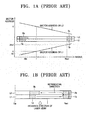
- FIG. 1A A sector address structure of a disk having dual information recording layers is shown in FIG. 1A .
- the disk in FIG. 1A has a first information recording layer L1 and a second information recording layer L2 that have lead-in areas 1a and 2a and lead-out areas 1b and 2b, respectively.
- a first sector address X is increased in a direction from an inner perimeter Rin of the disk to an outer perimeter Rout of the disk.
- a second sector address X' is increased in a direction from the outer perimeter Rout to the inner perimeter Rin of the disk.
- a multi-layered optical disk having more than two information recording layers can be divided into an opposite track path (OTP) and a parallel track path (PTP) based on directions of recording/reproducing data on/from the disk.
- the OTP reproduces data from the first information recording layer L1 in a direction from the inner perimeter Rin to the outer perimeter Rout and reproduces data from the second information recording layer L2 in a direction from the outer perimeter Rout to the inner perimeter Rin, as shown in FIG. 1B .
- the track spiral directions of the OTP optical disk are alternately formed on each of the information recording layers.
- FIG. 1C denotes an OTP multi-layered optical disk having first through fourth information recording layers L1, L2, L3, and L4.
- first through fourth lead-in areas 1a, 2a, 3a, and 4a and first through fourth lead-out areas 1b, 2b, 3b, and 4b are alternately formed at the inner perimeter regions and the outer perimeter regions of the first through fourth information recording layers L1, L2, L3, and L4 of the disk, respectively.
- the data is reproduced from the first information recording layer L1 in the direction from the inner perimeter Rin to the outer perimeter Rout, from the second information recording layer L2 in the direction from the outer perimeter Rout to the inner perimeter Rin, from the third information recording layer L3 in the direction from the inner perimeter Rin to the outer perimeter Rout, and from the fourth information recording layer L4 in the direction from the outer perimeter Rout to the inner perimeter Rin
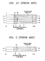
- FIG. 2 denotes a PTP dual-layered optical disk having a first information recording layer L1 from which data is reproduced in a direction from an inner perimeter Rin to an outer perimeter Rout and a second Information recording layer L2 from which data is reproduced in a direction from the inner perimeter Rin to the outer perimeter Rout.
- a first lead-in area 1 a is formed at the inner perimeter portion of the first information recording layer L1
- a first lead-out area 1b is formed at the outer perimeter portion of the first information recording layer L1
- a second lead-in area 2a is formed at the inner perimeter portion of the second information recording layer L2
- a second lead-out area 2b is formed at the outer perimeter portion of the second information recording layer L2.
- the lead-in areas 1a, 2a, 3a, and 4a and the lead-out areas 1b, 2b, 3b, and 4b include information about the disk and various conditions about recording. Accordingly, user data can be properly recorded and reproduced when reproducing the user data from the lead-in areas 1a, 2a, 3a, and 4a and the lead-out areas 1b, 2b, 3b, and 4b.
- the amount of the data to be recorded on the multi-layered information storage medium is smaller than the capacity of the information recording layers, there is an empty area on at least one information recording layer.
- FIG. 3A illustrates a single-layered recordable information storage medium
- FIG. 3B illustrates a dual layered recordable information storage medium. The locations and the capacities of lead-in areas, lead-out areas, and user data areas are fixed.
- the data may be recorded on the entire area of the data area of the first information recording layer L1 and on a portion of the data area of the second information recording layer L2, as shown in FIG. 4 .
- the beam may pass through a portion L1R of the first information recording layer L1 on which the data is recorded and a portion L2N of the second information recording layer L2 on which the data is not recorded, or the beam may pass through portions L1R and L2R of the first and second information recording layers L1 and L2 on which the data is recorded.
- a reproducing characteristic may be affected.
- the consistency and unity with the information storage medium of a particular type should be considered and the reproducing performance of a multi-layered in- formation storage medium should be considered.
- a conventional recordable DVD has a single information recording layer and a capacity of 4.7 GB.
- a conventional DVD-ROM has a capacity of 8.5 GB and dual information recording layers.
- a recordable DVD having the same capacity is required.
- a method of efficiently recording data is required to reduce a back-up time of the data.
- an information storage medium on which a layout structure of areas is defined to minimize a recording time and efficiently move a pickup between information recording layers, and a method of and a system recording data on the same are provided.
- a recordable in- formation storage medium having a plurality of Information recording layers, wherein each of the information recording layers includes a lead-in area, a user data area, a lead-out area, and a dedicated area for use with a drive, and the amount of user data to be recorded is divided to allot the data area having the same capacity on each of the in- formation recording layers.
- the location of the lead-out area varies according to the capacity of the data area.
- each dedicated area is arranged at the outmost perimeter of the information storage medium.
- the dedicated area is a test area.
- the location of the dedicated area may be fixed.
- each dedicated area is arranged at an outmost perimeter of each information recording layer of the information storage medium.
- a method of recording data on a recordable information storage medium having a plurality of information recording layers wherein each of the information recording layers includes a lead-in area, a user data area, a lead-out area, and a dedicated area for use with a drive, the method including performing a test on the dedicated area for the drive, dividing the amount of the user data to be recorded into the number of the information recording layers and recording the same amount of data on each of the information recording layers, and recording the data having a lead-out property following the data area of each of the information recording layers.
- a system for recording data on a recordable information storage medium having a plurality of information recording layers wherein each of the information recording layers includes a lead-in area, a user data area, a lead-out area, and a dedicated area for a drive, including a pickup unit radiating a beam to the information storage medium, a recording/reproducing signal process unit receiving the beam reflected on the information storage medium through the pickup unit and performing a signal process, and a control unit performing a test in the dedicated area for the drive and dividing the amount of user data to be recorded into the number of the information recording layers to record the same amount of data on each of the information recording layers.
- a method of improving recording and/or reproducing of data on recording layers of an information storage medium comprising: determining a size of data to be recorded on the information storage medium; determining operation information on a test area of each recording layer of the information storage medium; portioning the data such that an approximately equal amount is to be recorded in a data area of each recording layer; recording the portioned data in the data area of each recording layer of the information storage medium; and recording a lead-out property pattern to delineate the data area of each recording layer of the information storage medium.
- each test area is disposed near an outmost perimeter of the information storage medium.
- additional data is not recorded in an area between the delineated data area and the test area of each recording layer.
- an apparatus comprising: an optical pickup recording and/or reproducing data on/from recording layers of an Information storage medium; and a controller determining operation information of the information storage medium by controlling the optical pickup to perform tests in a fixed area of each recording layer of the information storage medium, determining a size of data to be recorded on the information storage medium, dividing the size of the data approximately equally among the recording layers, controlling the optical pickup to record the divided data in a data area of each of the recording layers and recording a lead-out property pattern delineating the data area.
- the lead-out property pattern is recorded in a lead-out area, a position of which varies depending on the divided size of the data.
- the fixed area is at an outmost perimeter of the information storage medium.
- An information storage medium provides a physical layout of a recordable information storage medium.
- the in- formation storage medium includes a plurality of information recording layers having lead-in areas, data areas, and lead-out areas, and the data areas are allotted to record approximately the same amount of data on each of the information recording layers.
- a layout for remaining areas after the recording of the data is provided to minimize a data recording time.
- An information storage medium has a plurality of information recording layers.
- each of the information recording layers includes a data area on which user data is recorded, and a lead-in area and a lead-out area that are arranged at an inner perimeter and an outer perimeter of the data area, respectively.
- the information storage medium according to an embodiment of the present invention may be applied to a recordable information storage medium, and more efficiently, to a recordable information storage medium on which the amount of data to be recorded is determined before recording data.
- the amount of data to be recorded is divided into the number of the information recording layers in order to record the same amount of data on each of the information recording layers.
- the capacities and the locations of the data areas and the lead-out areas may vary according to the amount of the data to be recorded.
- FIG. 5A illustrates an opposite track path (OTP) dual layer information storage medium
- FIG. 5B illustrates a parallel track path (PTP) dual layer information storage medium
- the dual layer information storage medium includes a first information recording layer L1 and a second information recording layer L2
- the information recording layers L1 and L2 include lead-in areas 20-L1 and 20-L2, data areas 30-L1 and 30-L2, and lead-out areas 40-L1 and 40-L2, respectively.
- the amount of data to be recorded is predetermined, the amount of data is divided into halves and each half is allotted to the data areas 30-L1 and 30-L2, respectively.
- the reference character C denotes the maximum of the user data to be recorded.
- the lead-out areas 40-L1 and 40-L2 arc arranged at the outer perimeters of the data areas 30-L1 and 30-L2 of the information recording layers to record the data in a pattern having a lead-out property.
- a location of the lead-out areas 40-L1 and 40-L2 varies depending on the amount of data recorded.
- the lead-in area and the lead-out area that arc located in the middle in a data recording direction may be referred to as a middle area or a connection area.
- the lead-out area 40-L1 of the first information recording layer L1 and the lead-out area 40-L2 of the second information recording layer L2 in FIG. 5A and the lead-out area 40-L1 of the first information recording layer L1 and the lead-in area 20-L2 of the second information recording layer L2 may be referred to as the middle areas or the connection areas.
- an information storage medium includes a dedicated area for use by a recording and/or reproducing apparatus (hereinafter referred to as a drive) in order for the drive to read recording information before recording user data.
- the dedicated area may include, for example, a test area for performing a test for detecting an optimum recording power of a recording medium and/or an area of recording information about recording histories of the drive.
- the test in the drive is performed before recording the user data, thus it is impossible to recognize the amount of data to be recorded. Therefore, the drive cannot determine the location of performing the test. As a result, the location of a test area should be fixed.
- test areas 45-L1 and 45-L2 may be fixed at the outmost perimeter of the information recording layers L1 and L2.
- the drive performs tests using the test areas 45-L1 and 45-L2 and records data. Thereafter, the drive records the pattern having the lead-out property at the outer perimeter of data areas 30-L1 and 30-L2, which are set depending on the size of the data to be recorded.
- the lead-out property is a data pattern to prohibit a pickup from separating from an information storage medium.
- the areas 43-L1 and 43-L2 between the lead-out areas 40-L1 and 40-L2 and the test areas 45-L1 and 45-L2, respectively, remain empty. Since the empty areas 43-L1 and 43-L2 are present, a recording time can be reduced compared to a case where the pattern having the lead-out property is recorded at the outmost perimeter of a recording medium.
- the recording may be performed according to an OTP type.
- FIGS. 6A and 6B illustrate an OTP multi-layered information storage medium and a PTP multi-layered information storage medium including first through fourth information recording layers L1, L2, L3, and L4, respectively.
- the first through fourth information recording layers L1, L2, L3, and L4 include lead-in areas 20-L1, 20-L2, 20-L3, and 20-L4, data areas 30-L1, 30-L2, 30-L3, and 30-L4, lead-out areas 40-L1, 40-L2, 40-L3, and 40-L4, and dedicated areas for a drive 45-L1, 45-L2, 45-L3, and 45-L4, respectively.
- the amount of data to be recorded is divided to be approximately equally distributed among the data areas 30-L1, 30-L2, 30-L3, and 30-L4 each having the same capacity that are formed on the first through fourth information recording layers L1, L2, L3, and L4, respectively.
- the lead-out areas 40-L1, 40-L2, 40-L3, and 40-L4 are arranged following the data areas 30-L1, 30-L2, 30-L3, and 30-L4 on which the user data is recorded.
- the reference character C designates a maximum amount of user data that may be recorded.
- the pattern having a lead-out property is recorded on the lead-out areas 40-L1, 40-L2, 40-L3, and 40-L4.
- the dedicated areas 45-L1, 45-L2, 45-L3, and 45-L4 may be arranged at the outmost perimeter of the information recording layers L1, L2, L3, and L4. When areas remain between the lead-out areas 40-L1, 40-L2, 40-L-3, and 40-L4 and the dedicated areas 45-L1, 45-L2, 45-L3, and 45-L4, these areas are empty 43-L 1, 43-L2, 43-L3 and 43-L4.
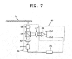
- FIG. 7 illustrates a system recording/reproducing data on/from an information storage medium according to an embodiment of the present invention.
- a system recording/reproducing data includes a pickup unit 50, a recording/reproducing signal process unit 60, and a control unit 70. More specifically, the system includes a laser diode 51 of radiating a beam, a collimating lens 52 of collimating the beam radiated from the laser diode 51, a beam splitter 54 of converting the path of the incidence beam, and an objective lens 56 of concentrating the beam from the beam splitter 54 on an information storage medium D.
- the beam reflected from the information storage medium D is reflected on the beam splitter 54 and received by an optical detector, for example, a quadrant optical detector 57.
- the beam received by the optical detector 57 is converted into electric signals by passing through an operation circuit unit 58 and output as RF signals,
- channel Ch1 detects a sum of signals
- differential signal channel Ch2 detects push-pull signals:
- the control unit 70 performs a test in test areas 45-L1 and 45-L2 of the information storage medium D before recording data on the information storage medium D.
- the control unit 70 records approximately the same amount of user data on each of the information recording layers L1 and L2 of the information storage medium D.
- the control unit 70 controls the pickup unit 50 to radiate a recording beam of a proper power, which is obtained by the test, to record the user data on the information storage medium D.
- the pattern of a lead-out property is recorded in at least one of the lead-out areas 40-L1 or 40-L2.
- control unit 70 finishes the recording without recording data on the areas 43-L1 and 43-L2 (i.e., the areas are left empty).
- a beam reflected from the information storage medium D is input to the optical detector 57 by passing through the objective lens 56 and the beam splitter 54.
- the signals input to the optical detector 57 are converted into electric signals by the operation circuit unit 58 and output as RF signals.
- a method of recording data recognizes the amount of data to be recorded on an information storage medium when the information storage medium is loaded on a drive, and performs a test on a dedicated area for the drive, for example, a test area of the information storage medium. Thereafter, the amount of the data is divided to allot data areas having approximately the same amount on each of information recording layers. Then, the data is recorded based on the allotted amount of data, and the data having a lead-out property is recorded following the data areas on the information recording layers,
Landscapes
- Physics & Mathematics (AREA)
- Optics & Photonics (AREA)
- Engineering & Computer Science (AREA)
- Signal Processing (AREA)
- Optical Recording Or Reproduction (AREA)
- Signal Processing For Digital Recording And Reproducing (AREA)
Applications Claiming Priority (2)
| Application Number | Priority Date | Filing Date | Title |
|---|---|---|---|
| KR1020040013788A KR100667753B1 (ko) | 2004-02-28 | 2004-02-28 | 정보 저장 매체, 데이터의 기록 방법 및 장치 |
| EP05726926A EP1733388B1 (de) | 2004-02-28 | 2005-02-24 | Informationsspeichermedium und Verfahren zum Aufzeichnen von Daten |
Related Parent Applications (2)
| Application Number | Title | Priority Date | Filing Date |
|---|---|---|---|
| EP05726926A Division EP1733388B1 (de) | 2004-02-28 | 2005-02-24 | Informationsspeichermedium und Verfahren zum Aufzeichnen von Daten |
| EP05726926.8 Division | 2005-02-24 |
Publications (2)
| Publication Number | Publication Date |
|---|---|
| EP2144236A1 true EP2144236A1 (de) | 2010-01-13 |
| EP2144236B1 EP2144236B1 (de) | 2011-10-26 |
Family
ID=36096987
Family Applications (2)
| Application Number | Title | Priority Date | Filing Date |
|---|---|---|---|
| EP05726926A Not-in-force EP1733388B1 (de) | 2004-02-28 | 2005-02-24 | Informationsspeichermedium und Verfahren zum Aufzeichnen von Daten |
| EP09173681A Not-in-force EP2144236B1 (de) | 2004-02-28 | 2005-02-24 | System und Vorrichtung zur Aufzeichnung von Daten auf einem Informationsspeichermedium |
Family Applications Before (1)
| Application Number | Title | Priority Date | Filing Date |
|---|---|---|---|
| EP05726926A Not-in-force EP1733388B1 (de) | 2004-02-28 | 2005-02-24 | Informationsspeichermedium und Verfahren zum Aufzeichnen von Daten |
Country Status (15)
| Country | Link |
|---|---|
| US (5) | US7502306B2 (de) |
| EP (2) | EP1733388B1 (de) |
| JP (1) | JP2007525784A (de) |
| KR (1) | KR100667753B1 (de) |
| CN (3) | CN101197142B (de) |
| AT (2) | ATE531043T1 (de) |
| BR (1) | BRPI0505979A (de) |
| CA (1) | CA2533651C (de) |
| ES (2) | ES2374694T3 (de) |
| HK (1) | HK1091592A1 (de) |
| MY (1) | MY141326A (de) |
| PL (1) | PL1733388T3 (de) |
| RU (2) | RU2340013C2 (de) |
| TW (1) | TWI304575B (de) |
| WO (1) | WO2005083690A1 (de) |
Families Citing this family (10)
| Publication number | Priority date | Publication date | Assignee | Title |
|---|---|---|---|---|
| KR100667753B1 (ko) * | 2004-02-28 | 2007-01-11 | 삼성전자주식회사 | 정보 저장 매체, 데이터의 기록 방법 및 장치 |
| KR101044938B1 (ko) | 2004-07-10 | 2011-06-28 | 삼성전자주식회사 | 복수의 기록층을 구비한 정보 저장 매체 및 기록/재생 장치 |
| JP4447574B2 (ja) * | 2005-06-30 | 2010-04-07 | シャープ株式会社 | 光ピックアップ、および光記録再生装置 |
| KR101244907B1 (ko) * | 2005-09-29 | 2013-03-18 | 삼성전자주식회사 | 프리피트가 형성된 정보 저장 매체 및 기록/재생 장치 및기록/재생 방법 |
| US20080068965A1 (en) * | 2006-09-20 | 2008-03-20 | Yoshiho Gotoh | Data processing apparatus, recorder and disk with multiple storage layers |
| TW200830304A (en) * | 2007-01-05 | 2008-07-16 | Ind Tech Res Inst | Continue addressing multi-layer optical disk and addressing method thereof |
| JP2010160863A (ja) * | 2009-01-09 | 2010-07-22 | Hitachi Ltd | 光ディスク装置及び多層式ディスク |
| JP5163791B2 (ja) * | 2011-08-19 | 2013-03-13 | 株式会社日立製作所 | 多層記録型ディスクの多重記録方法、多層記録型ディスクの多重記録装置、及び多重記録された多層記録型ディスクの再生方法 |
| JP2015060617A (ja) * | 2013-09-20 | 2015-03-30 | 株式会社東芝 | ディスク装置およびデータ記録方法 |
| US9928868B2 (en) | 2014-02-28 | 2018-03-27 | Memory-Tech Holdings, Inc. | Optical disc having a plurality of recording layers |
Citations (5)
| Publication number | Priority date | Publication date | Assignee | Title |
|---|---|---|---|---|
| EP0715301A2 (de) * | 1994-11-30 | 1996-06-05 | Sony Corporation | Datenaufzeichnungsträger und dessen Aufzeichnen/Wiedergabe |
| WO2000079525A1 (fr) * | 1999-06-22 | 2000-12-28 | Matsushita Electric Industrial Co., Ltd. | Disque optique, dispositif de disque optique, et procede de reproduction pour disque optique |
| EP1244096A2 (de) * | 2001-03-21 | 2002-09-25 | Nippon Columbia Co., Ltd. | Optisches Informationsaufzeichnungsmedium, Verfahren zur Informationsaufzeichnung auf einen Verfahren zur Aufzeichnung von Information auf einem optischen Informationsaufzeichnungsmedium und Informationsaufzeichnungsgerät |
| JP2003168216A (ja) * | 2001-11-29 | 2003-06-13 | Sony Corp | 光記録媒体、並びに、光記録媒体に対する記録装置及び方法 |
| US20030137915A1 (en) * | 2002-01-22 | 2003-07-24 | Mamoru Shoji | Information recording medium, recording apparatus, reproduction apparatus, recording method, and reproduction method |
Family Cites Families (26)
| Publication number | Priority date | Publication date | Assignee | Title |
|---|---|---|---|---|
| JPH08212561A (ja) * | 1994-11-30 | 1996-08-20 | Sony Corp | データ記録媒体およびそのデータ記録媒体を使用する記録/再生装置 |
| US5729525A (en) * | 1995-06-21 | 1998-03-17 | Matsushita Electric Industrial Co., Ltd. | Two-layer optical disk |
| JP3756574B2 (ja) | 1995-06-21 | 2006-03-15 | 松下電器産業株式会社 | 2層光ディスク |
| JPH09106625A (ja) * | 1995-10-06 | 1997-04-22 | Victor Co Of Japan Ltd | 光記録媒体及びその再生装置 |
| EP0856186B1 (de) | 1995-10-19 | 2000-06-28 | Matsushita Electric Industrial Co., Ltd. | Informationsspeichermedium, informationswiedergabeverfahren und informationswiedergabegerät |
| JP3707137B2 (ja) | 1996-07-04 | 2005-10-19 | ソニー株式会社 | 記録媒体、再生装置 |
| EP1345215A3 (de) * | 1996-07-10 | 2004-09-15 | Hitachi, Ltd. | Verfahren und System zum Datenzugriff für einen optischen Plattenspieler |
| US6058086A (en) * | 1996-12-19 | 2000-05-02 | Lg Electronics, Inc. | Method and apparatus for testing quality of an optical disk medium |
| JPH1131357A (ja) * | 1997-07-08 | 1999-02-02 | Pioneer Electron Corp | 情報データの記録方法 |
| JP3994539B2 (ja) | 1998-08-25 | 2007-10-24 | ソニー株式会社 | 再生装置 |
| JP2000123494A (ja) | 1998-10-12 | 2000-04-28 | Kenwood Corp | 多層光ディスク |
| KR100544175B1 (ko) * | 1999-05-08 | 2006-01-23 | 삼성전자주식회사 | 링킹 타입 정보를 저장하는 기록 매체와 결함 영역 처리 방법 |
| JP2001023351A (ja) * | 1999-07-09 | 2001-01-26 | Hitachi Maxell Ltd | 光ディスク及び光ディスク駆動装置 |
| JP2001291344A (ja) * | 2000-04-04 | 2001-10-19 | Hitachi Ltd | 光ディスク装置およびそのデータ再生方法 |
| EP1176586B1 (de) | 2000-07-26 | 2005-09-14 | Kabushiki Kaisha Toshiba | Aufzeichnungsträger für Informationen mit einem Indexstartfeld |
| JP2002050053A (ja) | 2000-08-01 | 2002-02-15 | Tdk Corp | 光情報媒体 |
| CA2410779C (en) | 2000-09-13 | 2009-07-07 | Matsushita Electric Industrial Co., Ltd. | Optical information recording medium, optical information recording method, and optical information recording apparatus |
| JP2003022532A (ja) * | 2001-07-06 | 2003-01-24 | Columbia Music Entertainment Inc | 光情報記録媒体ならびにその記録方法および情報記録装置 |
| JP3545725B2 (ja) * | 2001-06-07 | 2004-07-21 | 株式会社東芝 | 光ディスク |
| JP3947428B2 (ja) * | 2001-09-10 | 2007-07-18 | 株式会社リコー | 情報記録再生装置及びそのシステム |
| US6801494B2 (en) * | 2001-10-31 | 2004-10-05 | Koninklijke Philips Electronics N.V. | Multiple sections for dual-layer optical recording medium |
| KR100911139B1 (ko) * | 2002-05-30 | 2009-08-06 | 삼성전자주식회사 | 복수개의 기록층이 구비된 광 디스크, 그 기록방법 및재생방법 |
| JP2004310972A (ja) | 2003-03-25 | 2004-11-04 | Ricoh Co Ltd | 情報処理装置、情報記録装置、情報処理システム、情報記録方法、情報記録用プログラム及び記憶媒体 |
| CN1227658C (zh) * | 2003-06-23 | 2005-11-16 | 清华大学 | 一种用于数据存储和读取的无孔光盘 |
| RU2006102856A (ru) * | 2003-07-01 | 2006-07-27 | Конинклейке Филипс Электроникс Н.В. (Nl) | Способы и устройства записи для записи информации на двухслойном записываемом диске |
| KR100667753B1 (ko) * | 2004-02-28 | 2007-01-11 | 삼성전자주식회사 | 정보 저장 매체, 데이터의 기록 방법 및 장치 |
-
2004
- 2004-02-28 KR KR1020040013788A patent/KR100667753B1/ko active IP Right Grant
- 2004-12-29 US US11/023,591 patent/US7502306B2/en not_active Expired - Fee Related
-
2005
- 2005-02-17 TW TW094104595A patent/TWI304575B/zh not_active IP Right Cessation
- 2005-02-24 ES ES09173681T patent/ES2374694T3/es active Active
- 2005-02-24 EP EP05726926A patent/EP1733388B1/de not_active Not-in-force
- 2005-02-24 PL PL05726926T patent/PL1733388T3/pl unknown
- 2005-02-24 WO PCT/KR2005/000512 patent/WO2005083690A1/en active Application Filing
- 2005-02-24 CN CN2007103011775A patent/CN101197142B/zh not_active Expired - Fee Related
- 2005-02-24 BR BRPI0505979-8A patent/BRPI0505979A/pt not_active Application Discontinuation
- 2005-02-24 CN CNB2005800006079A patent/CN100373471C/zh not_active Expired - Fee Related
- 2005-02-24 ES ES05726926T patent/ES2373316T3/es active Active
- 2005-02-24 JP JP2007500680A patent/JP2007525784A/ja active Pending
- 2005-02-24 RU RU2006130794/28A patent/RU2340013C2/ru not_active IP Right Cessation
- 2005-02-24 CN CN2007103011760A patent/CN101197141B/zh not_active Expired - Fee Related
- 2005-02-24 EP EP09173681A patent/EP2144236B1/de not_active Not-in-force
- 2005-02-24 AT AT09173681T patent/ATE531043T1/de not_active IP Right Cessation
- 2005-02-24 CA CA2533651A patent/CA2533651C/en not_active Expired - Fee Related
- 2005-02-24 AT AT05726926T patent/ATE526665T1/de not_active IP Right Cessation
- 2005-02-25 MY MYPI20050767A patent/MY141326A/en unknown
- 2005-08-18 US US11/206,206 patent/US7518977B2/en not_active Expired - Fee Related
-
2006
- 2006-05-12 US US11/432,395 patent/US7518979B2/en not_active Expired - Fee Related
- 2006-05-12 US US11/432,394 patent/US7518978B2/en not_active Expired - Fee Related
- 2006-05-12 US US11/432,392 patent/US7529174B2/en not_active Expired - Fee Related
- 2006-11-06 HK HK06112189A patent/HK1091592A1/xx not_active IP Right Cessation
-
2008
- 2008-06-19 RU RU2008125023/28A patent/RU2488177C2/ru not_active IP Right Cessation
Patent Citations (6)
| Publication number | Priority date | Publication date | Assignee | Title |
|---|---|---|---|---|
| EP0715301A2 (de) * | 1994-11-30 | 1996-06-05 | Sony Corporation | Datenaufzeichnungsträger und dessen Aufzeichnen/Wiedergabe |
| WO2000079525A1 (fr) * | 1999-06-22 | 2000-12-28 | Matsushita Electric Industrial Co., Ltd. | Disque optique, dispositif de disque optique, et procede de reproduction pour disque optique |
| US20050259561A1 (en) * | 1999-06-22 | 2005-11-24 | Atsushi Nakamura | Optical disc, optical disc drive, and optical disc playback method |
| EP1244096A2 (de) * | 2001-03-21 | 2002-09-25 | Nippon Columbia Co., Ltd. | Optisches Informationsaufzeichnungsmedium, Verfahren zur Informationsaufzeichnung auf einen Verfahren zur Aufzeichnung von Information auf einem optischen Informationsaufzeichnungsmedium und Informationsaufzeichnungsgerät |
| JP2003168216A (ja) * | 2001-11-29 | 2003-06-13 | Sony Corp | 光記録媒体、並びに、光記録媒体に対する記録装置及び方法 |
| US20030137915A1 (en) * | 2002-01-22 | 2003-07-24 | Mamoru Shoji | Information recording medium, recording apparatus, reproduction apparatus, recording method, and reproduction method |
Also Published As
Similar Documents
| Publication | Publication Date | Title |
|---|---|---|
| EP2144236B1 (de) | System und Vorrichtung zur Aufzeichnung von Daten auf einem Informationsspeichermedium | |
| WO2005001825A1 (en) | Information storage medium | |
| US7512046B2 (en) | Optical disk apparatus and method for controlling the same | |
| EP1803119B1 (de) | Vorrichtung und verfahren zur aufzeichnung und wiedergabe eines informationsspeichermediums | |
| EP1644921B1 (de) | Aufzeichnungsverfahren und einrichtung zur aufzeichnung von informationen auf beschreibbaren datenträgern mit doppelschicht | |
| US7440378B2 (en) | Information storage medium and method and apparatus for recording/reproducing data | |
| US8351314B2 (en) | Optical disc having plurality of recording layers, and method and apparatus for recording data thereon | |
| KR101044938B1 (ko) | 복수의 기록층을 구비한 정보 저장 매체 및 기록/재생 장치 | |
| KR101044951B1 (ko) | 복수의 기록층을 구비한 정보 저장 매체의 기록/재생 방법 | |
| JP2005531872A (ja) | 情報保存媒体及びその記録及び/または再生方法 | |
| KR101058046B1 (ko) | 복수의 기록층을 구비한 정보 저장 매체 및 기록/재생 장치 |
Legal Events
| Date | Code | Title | Description |
|---|---|---|---|
| PUAI | Public reference made under article 153(3) epc to a published international application that has entered the european phase |
Free format text: ORIGINAL CODE: 0009012 |
|
| AC | Divisional application: reference to earlier application |
Ref document number: 1733388 Country of ref document: EP Kind code of ref document: P |
|
| AK | Designated contracting states |
Kind code of ref document: A1 Designated state(s): AT BE BG CH CY CZ DE DK EE ES FI FR GB GR HU IE IS IT LI LT LU MC NL PL PT RO SE SI SK TR |
|
| 17P | Request for examination filed |
Effective date: 20100713 |
|
| 17Q | First examination report despatched |
Effective date: 20100805 |
|
| GRAP | Despatch of communication of intention to grant a patent |
Free format text: ORIGINAL CODE: EPIDOSNIGR1 |
|
| RIC1 | Information provided on ipc code assigned before grant |
Ipc: G11B 7/007 20060101AFI20110314BHEP Ipc: G11B 7/125 20060101ALI20110314BHEP |
|
| GRAS | Grant fee paid |
Free format text: ORIGINAL CODE: EPIDOSNIGR3 |
|
| GRAA | (expected) grant |
Free format text: ORIGINAL CODE: 0009210 |
|
| AC | Divisional application: reference to earlier application |
Ref document number: 1733388 Country of ref document: EP Kind code of ref document: P |
|
| AK | Designated contracting states |
Kind code of ref document: B1 Designated state(s): AT BE BG CH CY CZ DE DK EE ES FI FR GB GR HU IE IS IT LI LT LU MC NL PL PT RO SE SI SK TR |
|
| REG | Reference to a national code |
Ref country code: GB Ref legal event code: FG4D |
|
| REG | Reference to a national code |
Ref country code: CH Ref legal event code: EP |
|
| REG | Reference to a national code |
Ref country code: IE Ref legal event code: FG4D |
|
| REG | Reference to a national code |
Ref country code: DE Ref legal event code: R096 Ref document number: 602005030890 Country of ref document: DE Effective date: 20120105 |
|
| REG | Reference to a national code |
Ref country code: NL Ref legal event code: VDEP Effective date: 20111026 |
|
| REG | Reference to a national code |
Ref country code: ES Ref legal event code: FG2A Ref document number: 2374694 Country of ref document: ES Kind code of ref document: T3 Effective date: 20120221 |
|
| LTIE | Lt: invalidation of european patent or patent extension |
Effective date: 20111026 |
|
| REG | Reference to a national code |
Ref country code: AT Ref legal event code: MK05 Ref document number: 531043 Country of ref document: AT Kind code of ref document: T Effective date: 20111026 |
|
| PG25 | Lapsed in a contracting state [announced via postgrant information from national office to epo] |
Ref country code: BE Free format text: LAPSE BECAUSE OF FAILURE TO SUBMIT A TRANSLATION OF THE DESCRIPTION OR TO PAY THE FEE WITHIN THE PRESCRIBED TIME-LIMIT Effective date: 20111026 Ref country code: LT Free format text: LAPSE BECAUSE OF FAILURE TO SUBMIT A TRANSLATION OF THE DESCRIPTION OR TO PAY THE FEE WITHIN THE PRESCRIBED TIME-LIMIT Effective date: 20111026 Ref country code: IS Free format text: LAPSE BECAUSE OF FAILURE TO SUBMIT A TRANSLATION OF THE DESCRIPTION OR TO PAY THE FEE WITHIN THE PRESCRIBED TIME-LIMIT Effective date: 20120226 |
|
| PG25 | Lapsed in a contracting state [announced via postgrant information from national office to epo] |
Ref country code: NL Free format text: LAPSE BECAUSE OF FAILURE TO SUBMIT A TRANSLATION OF THE DESCRIPTION OR TO PAY THE FEE WITHIN THE PRESCRIBED TIME-LIMIT Effective date: 20111026 Ref country code: SE Free format text: LAPSE BECAUSE OF FAILURE TO SUBMIT A TRANSLATION OF THE DESCRIPTION OR TO PAY THE FEE WITHIN THE PRESCRIBED TIME-LIMIT Effective date: 20111026 Ref country code: GR Free format text: LAPSE BECAUSE OF FAILURE TO SUBMIT A TRANSLATION OF THE DESCRIPTION OR TO PAY THE FEE WITHIN THE PRESCRIBED TIME-LIMIT Effective date: 20120127 Ref country code: PL Free format text: LAPSE BECAUSE OF FAILURE TO SUBMIT A TRANSLATION OF THE DESCRIPTION OR TO PAY THE FEE WITHIN THE PRESCRIBED TIME-LIMIT Effective date: 20111026 Ref country code: PT Free format text: LAPSE BECAUSE OF FAILURE TO SUBMIT A TRANSLATION OF THE DESCRIPTION OR TO PAY THE FEE WITHIN THE PRESCRIBED TIME-LIMIT Effective date: 20120227 Ref country code: SI Free format text: LAPSE BECAUSE OF FAILURE TO SUBMIT A TRANSLATION OF THE DESCRIPTION OR TO PAY THE FEE WITHIN THE PRESCRIBED TIME-LIMIT Effective date: 20111026 |
|
| PG25 | Lapsed in a contracting state [announced via postgrant information from national office to epo] |
Ref country code: CY Free format text: LAPSE BECAUSE OF FAILURE TO SUBMIT A TRANSLATION OF THE DESCRIPTION OR TO PAY THE FEE WITHIN THE PRESCRIBED TIME-LIMIT Effective date: 20111026 |
|
| PG25 | Lapsed in a contracting state [announced via postgrant information from national office to epo] |
Ref country code: EE Free format text: LAPSE BECAUSE OF FAILURE TO SUBMIT A TRANSLATION OF THE DESCRIPTION OR TO PAY THE FEE WITHIN THE PRESCRIBED TIME-LIMIT Effective date: 20111026 Ref country code: SK Free format text: LAPSE BECAUSE OF FAILURE TO SUBMIT A TRANSLATION OF THE DESCRIPTION OR TO PAY THE FEE WITHIN THE PRESCRIBED TIME-LIMIT Effective date: 20111026 Ref country code: DK Free format text: LAPSE BECAUSE OF FAILURE TO SUBMIT A TRANSLATION OF THE DESCRIPTION OR TO PAY THE FEE WITHIN THE PRESCRIBED TIME-LIMIT Effective date: 20111026 Ref country code: CZ Free format text: LAPSE BECAUSE OF FAILURE TO SUBMIT A TRANSLATION OF THE DESCRIPTION OR TO PAY THE FEE WITHIN THE PRESCRIBED TIME-LIMIT Effective date: 20111026 Ref country code: BG Free format text: LAPSE BECAUSE OF FAILURE TO SUBMIT A TRANSLATION OF THE DESCRIPTION OR TO PAY THE FEE WITHIN THE PRESCRIBED TIME-LIMIT Effective date: 20120126 |
|
| PG25 | Lapsed in a contracting state [announced via postgrant information from national office to epo] |
Ref country code: RO Free format text: LAPSE BECAUSE OF FAILURE TO SUBMIT A TRANSLATION OF THE DESCRIPTION OR TO PAY THE FEE WITHIN THE PRESCRIBED TIME-LIMIT Effective date: 20111026 |
|
| PLBE | No opposition filed within time limit |
Free format text: ORIGINAL CODE: 0009261 |
|
| STAA | Information on the status of an ep patent application or granted ep patent |
Free format text: STATUS: NO OPPOSITION FILED WITHIN TIME LIMIT |
|
| RAP2 | Party data changed (patent owner data changed or rights of a patent transferred) |
Owner name: SAMSUNG ELECTRONICS CO., LTD. |
|
| PG25 | Lapsed in a contracting state [announced via postgrant information from national office to epo] |
Ref country code: MC Free format text: LAPSE BECAUSE OF NON-PAYMENT OF DUE FEES Effective date: 20120229 |
|
| REG | Reference to a national code |
Ref country code: CH Ref legal event code: PL |
|
| 26N | No opposition filed |
Effective date: 20120727 |
|
| PG25 | Lapsed in a contracting state [announced via postgrant information from national office to epo] |
Ref country code: CH Free format text: LAPSE BECAUSE OF NON-PAYMENT OF DUE FEES Effective date: 20120229 Ref country code: LI Free format text: LAPSE BECAUSE OF NON-PAYMENT OF DUE FEES Effective date: 20120229 |
|
| REG | Reference to a national code |
Ref country code: IE Ref legal event code: MM4A |
|
| REG | Reference to a national code |
Ref country code: DE Ref legal event code: R097 Ref document number: 602005030890 Country of ref document: DE Effective date: 20120727 |
|
| PG25 | Lapsed in a contracting state [announced via postgrant information from national office to epo] |
Ref country code: AT Free format text: LAPSE BECAUSE OF FAILURE TO SUBMIT A TRANSLATION OF THE DESCRIPTION OR TO PAY THE FEE WITHIN THE PRESCRIBED TIME-LIMIT Effective date: 20111026 Ref country code: IE Free format text: LAPSE BECAUSE OF NON-PAYMENT OF DUE FEES Effective date: 20120224 |
|
| PG25 | Lapsed in a contracting state [announced via postgrant information from national office to epo] |
Ref country code: FI Free format text: LAPSE BECAUSE OF FAILURE TO SUBMIT A TRANSLATION OF THE DESCRIPTION OR TO PAY THE FEE WITHIN THE PRESCRIBED TIME-LIMIT Effective date: 20111026 |
|
| PG25 | Lapsed in a contracting state [announced via postgrant information from national office to epo] |
Ref country code: TR Free format text: LAPSE BECAUSE OF FAILURE TO SUBMIT A TRANSLATION OF THE DESCRIPTION OR TO PAY THE FEE WITHIN THE PRESCRIBED TIME-LIMIT Effective date: 20111026 |
|
| PG25 | Lapsed in a contracting state [announced via postgrant information from national office to epo] |
Ref country code: LU Free format text: LAPSE BECAUSE OF NON-PAYMENT OF DUE FEES Effective date: 20120224 |
|
| PG25 | Lapsed in a contracting state [announced via postgrant information from national office to epo] |
Ref country code: HU Free format text: LAPSE BECAUSE OF FAILURE TO SUBMIT A TRANSLATION OF THE DESCRIPTION OR TO PAY THE FEE WITHIN THE PRESCRIBED TIME-LIMIT Effective date: 20050224 |
|
| REG | Reference to a national code |
Ref country code: FR Ref legal event code: PLFP Year of fee payment: 12 |
|
| REG | Reference to a national code |
Ref country code: FR Ref legal event code: PLFP Year of fee payment: 13 |
|
| REG | Reference to a national code |
Ref country code: FR Ref legal event code: PLFP Year of fee payment: 14 |
|
| PGFP | Annual fee paid to national office [announced via postgrant information from national office to epo] |
Ref country code: FR Payment date: 20190124 Year of fee payment: 15 Ref country code: GB Payment date: 20190122 Year of fee payment: 15 Ref country code: DE Payment date: 20190122 Year of fee payment: 15 Ref country code: ES Payment date: 20190313 Year of fee payment: 15 Ref country code: IT Payment date: 20190208 Year of fee payment: 15 |
|
| REG | Reference to a national code |
Ref country code: DE Ref legal event code: R119 Ref document number: 602005030890 Country of ref document: DE |
|
| GBPC | Gb: european patent ceased through non-payment of renewal fee |
Effective date: 20200224 |
|
| PG25 | Lapsed in a contracting state [announced via postgrant information from national office to epo] |
Ref country code: FR Free format text: LAPSE BECAUSE OF NON-PAYMENT OF DUE FEES Effective date: 20200229 Ref country code: DE Free format text: LAPSE BECAUSE OF NON-PAYMENT OF DUE FEES Effective date: 20200901 Ref country code: GB Free format text: LAPSE BECAUSE OF NON-PAYMENT OF DUE FEES Effective date: 20200224 |
|
| REG | Reference to a national code |
Ref country code: ES Ref legal event code: FD2A Effective date: 20210708 |
|
| PG25 | Lapsed in a contracting state [announced via postgrant information from national office to epo] |
Ref country code: IT Free format text: LAPSE BECAUSE OF NON-PAYMENT OF DUE FEES Effective date: 20200224 |
|
| PG25 | Lapsed in a contracting state [announced via postgrant information from national office to epo] |
Ref country code: ES Free format text: LAPSE BECAUSE OF NON-PAYMENT OF DUE FEES Effective date: 20200225 |